WO2023163220A1 - 粒子線治療設備、及び粒子線治療装置 - Google Patents
粒子線治療設備、及び粒子線治療装置 Download PDFInfo
- Publication number
- WO2023163220A1 WO2023163220A1 PCT/JP2023/007355 JP2023007355W WO2023163220A1 WO 2023163220 A1 WO2023163220 A1 WO 2023163220A1 JP 2023007355 W JP2023007355 W JP 2023007355W WO 2023163220 A1 WO2023163220 A1 WO 2023163220A1
- Authority
- WO
- WIPO (PCT)
- Prior art keywords
- treatment
- room
- preparation
- particle beam
- rooms
- Prior art date
- Legal status (The legal status is an assumption and is not a legal conclusion. Google has not performed a legal analysis and makes no representation as to the accuracy of the status listed.)
- Ceased
Links
Images




Classifications
-
- A—HUMAN NECESSITIES
- A61—MEDICAL OR VETERINARY SCIENCE; HYGIENE
- A61N—ELECTROTHERAPY; MAGNETOTHERAPY; RADIATION THERAPY; ULTRASOUND THERAPY
- A61N5/00—Radiation therapy
- A61N5/10—X-ray therapy; Gamma-ray therapy; Particle-irradiation therapy
-
- A—HUMAN NECESSITIES
- A61—MEDICAL OR VETERINARY SCIENCE; HYGIENE
- A61N—ELECTROTHERAPY; MAGNETOTHERAPY; RADIATION THERAPY; ULTRASOUND THERAPY
- A61N5/00—Radiation therapy
- A61N5/10—X-ray therapy; Gamma-ray therapy; Particle-irradiation therapy
- A61N5/1077—Beam delivery systems
- A61N5/1078—Fixed beam systems
-
- A—HUMAN NECESSITIES
- A61—MEDICAL OR VETERINARY SCIENCE; HYGIENE
- A61N—ELECTROTHERAPY; MAGNETOTHERAPY; RADIATION THERAPY; ULTRASOUND THERAPY
- A61N5/00—Radiation therapy
- A61N5/10—X-ray therapy; Gamma-ray therapy; Particle-irradiation therapy
- A61N5/1077—Beam delivery systems
- A61N5/1079—Sharing a beam by multiple treatment stations
-
- A—HUMAN NECESSITIES
- A61—MEDICAL OR VETERINARY SCIENCE; HYGIENE
- A61N—ELECTROTHERAPY; MAGNETOTHERAPY; RADIATION THERAPY; ULTRASOUND THERAPY
- A61N5/00—Radiation therapy
- A61N5/10—X-ray therapy; Gamma-ray therapy; Particle-irradiation therapy
- A61N2005/1085—X-ray therapy; Gamma-ray therapy; Particle-irradiation therapy characterised by the type of particles applied to the patient
- A61N2005/1087—Ions; Protons
-
- A—HUMAN NECESSITIES
- A61—MEDICAL OR VETERINARY SCIENCE; HYGIENE
- A61N—ELECTROTHERAPY; MAGNETOTHERAPY; RADIATION THERAPY; ULTRASOUND THERAPY
- A61N5/00—Radiation therapy
- A61N5/10—X-ray therapy; Gamma-ray therapy; Particle-irradiation therapy
- A61N2005/1085—X-ray therapy; Gamma-ray therapy; Particle-irradiation therapy characterised by the type of particles applied to the patient
- A61N2005/109—Neutrons
Definitions
- the present disclosure relates to particle beam therapy equipment and particle beam therapy equipment.
- BNCT Boron Neutron Capture Therapy using a boron compound
- a neutron capture therapy that kills cancer cells by irradiating neutron beams.
- cancer cells are selectively destroyed by scattering heavy charged particles generated by irradiating neutron beams to boron pre-loaded into cancer cells.
- the neutron beam generator shown in Patent Document 1 is used as a device that generates neutron beams for the purposes described above.
- the neutron beam generator disclosed in Patent Literature 1 performs treatment by placing a patient fixed on a mounting member in front of a neutron beam irradiation port.
- a preparation room is provided as a separate room from the treatment room.
- the size of the particle beam therapy equipment increases when a plurality of sets are provided in which one treatment room is provided with one preparation room.
- an object of the present disclosure is to provide a particle beam therapy facility and a particle beam therapy apparatus that can be downsized.
- the particle beam therapy equipment includes a treatment room that performs particle beam therapy independently from other rooms, a plurality of preparation rooms that prepare for treatment, and a treatment room and a preparation room that are independent from other rooms.
- the relay room has one continuous space that connects the treatment room doorway of the treatment room and the preparation room doorway of each of the plurality of preparation rooms.
- the particle beam therapy equipment includes a relay room that relays between the treatment room and the preparation room.
- the relay room has one continuous space that connects the treatment room doorway of the treatment room and the preparation room doorways of the plurality of preparation rooms. Therefore, in the particle beam therapy equipment, regardless of which preparation room the object to be treated is to be transferred, the object can be quickly transferred by passing through the common space of the relay room. Therefore, the layout between the treatment room and the plurality of preparation rooms can be made compact. As described above, it is possible to reduce the size of the equipment.
- the particle beam therapy equipment is supported by a support section provided in the relay room and by the support section so as to be movable between a plurality of preparation rooms and treatment rooms. and a transport mechanism for transporting.
- the particle beam therapy equipment can quickly transport the object to be treated from any preparation room using the common transport mechanism supported by the support part of the relay room. Therefore, the layout between the treatment room and the plurality of preparation rooms can be made compact. As described above, it is possible to reduce the size of the equipment.
- the transport mechanism may be rotatable around a vertically extending central axis. As a result, the transport mechanism rotates to orient the transport arm toward the desired room, thereby enabling rapid transport.
- Multiple preparation rooms may be arranged to surround the relay room. In this case, it is possible to increase the number of preparation chambers that can be arranged with respect to the area of the relay chamber.
- a boron concentration measurement room that measures the boron concentration of the treatment target independently of other rooms may be further provided. In this case, since the boron concentration can be measured quickly from the object to be treated, the personnel and time required for measurement can be reduced.
- a particle beam therapy apparatus includes a support unit provided between a treatment unit that performs particle beam therapy and a plurality of preparation units that prepare for treatment, and movement between the plurality of preparation units and the treatment unit. a transport mechanism that is supported by the supporting part and transports the object to be treated between the plurality of preparation parts and the treatment part.
- a particle beam therapy apparatus includes a support section between a treatment section and a plurality of preparation sections.
- the particle beam therapy system also includes a transport mechanism that is supported by the support part so as to be movable between the plurality of preparation parts and the treatment part, and that transports the treatment target between the plurality of preparation parts and the treatment part. Therefore, the particle beam therapy system can quickly transport the object to be treated by using the common transport mechanism supported by the support part, regardless of which preparation part the object to be treated is transported. Therefore, the layout between the treatment section and the plurality of preparation sections can be made compact. As described above, it is possible to reduce the size of the equipment.
- the particle beam therapy system consists of a treatment room provided with a treatment section, a plurality of preparation rooms each provided with a preparation section, and a transport mechanism provided independently of the other rooms.
- a relay room that relays the room and the preparation room may be provided.
- a plurality of preparation rooms are provided for one independent treatment room. Therefore, while preparations for treatment in a treatment room are being made in one preparation room, treatment simulation can be performed in another preparation room. As a result, the simulation room can be omitted, so that the size of the equipment can be reduced.
- the particle beam therapy system includes a relay room that relays between the treatment room and the preparation room. Further, the relay room is provided with a transport mechanism for transporting the object to be treated between the treatment room and the preparation room.
- the particle beam therapy equipment can use the common transport mechanism of the relay room to quickly transport the object to be treated from any preparation room. Therefore, the layout between the treatment room and the plurality of preparation rooms can be made compact. As described above, it is possible to reduce the size of the equipment.
- a plurality of preparation units may be arranged so as to surround the transport mechanism. In this case, it is possible to increase the number of preparation parts that can be arranged with respect to the area of the relay chamber.
- the transport mechanism may have a transport arm rotatable around a vertically extending central axis. As a result, the transport mechanism rotates to orient the transport arm toward the desired room, thereby enabling rapid transport.
- the support section is provided between the treatment section, the plurality of preparation sections, and an imaging section that photographs the treatment target, and the transport mechanism is movable between the plurality of preparation sections, the imaging section, and the treatment section.
- the particle beam therapy system performs a treatment simulation in a preparation section to determine the fixing position of the treatment target. Position confirmation can be performed.
- the imaging section is provided near the preparation section, preparations immediately before treatment can be performed in the same preparation section where the simulation was performed. In this case, it is not necessary to correct the alignment error between the time of simulation and the time of actual treatment preparation, so the preparation time immediately before treatment can be shortened.
- the particle beam therapy system is independent from other rooms and further includes an imaging room provided with an imaging unit, and the imaging room images a treatment target prepared in each of a plurality of preparation rooms each provided with a preparation unit. It may be possible. In this case, the particle beam therapy system performs a treatment simulation in a preparation room to determine the fixation position of the treatment target. Position confirmation can be performed. In addition, since the imaging room is provided near the preparation room, preparations immediately before treatment can be performed in the same preparation room as the preparation room where the simulation was performed. In this case, it is not necessary to correct the alignment error between the time of simulation and the time of actual treatment preparation, so the preparation time immediately before treatment can be shortened.
- the transport mechanism transports the first treatment target from the first preparation section to the treatment section, and transfers the first treatment target from the second preparation section to the treatment section other than the treatment section while the first treatment target is being treated in the treatment section.
- the second treatment object may be transported to a plurality of preparation units or an imaging unit for imaging the treatment object. In this case, at the same time as the treatment of the first treatment target, preparations for treatment of another second treatment target can be advanced in another preparation section.
- the transport mechanism transports the first treatment object from the first preparation unit to the imaging unit that photographs the treatment object, and during the imaging of the first treatment object by the imaging unit, or during the imaging of the first treatment object by the first preparation unit.
- a second treatment object may be transported from the second preparation station to the treatment station during preparation at . In this case, at the same time as the simulation of the first treatment target or imaging for confirming the simulation, treatment of another second treatment target can proceed in another preparation room.
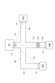
- FIG. 1 is a schematic diagram showing a particle beam therapy facility and a particle beam therapy apparatus according to an embodiment of the present disclosure
- FIG. It is a schematic diagram showing a neutron beam generator.
- It is a schematic diagram showing a particle beam therapy equipment according to a comparative example.
- It is a figure which shows the operation
- FIG. 5 is a diagram showing operation timings of a particle beam therapy facility according to a comparative example;
- FIG. 4 is a diagram showing operation timings of the particle beam therapy equipment according to the embodiment; It is the table
- It is a schematic diagram showing a particle beam therapy equipment according to a modification.
- FIG. 1 is a schematic diagram showing a particle beam therapy facility 100 and a particle beam therapy device 250 according to an embodiment of the present disclosure.
- the particle beam therapy facility 100 is a facility that performs treatment using neutron beams generated by the neutron beam generator 1 as particle beams.
- the particle beam therapy apparatus 250 is an apparatus that performs treatment using neutron beams generated by the neutron beam generator 1 as particle beams.
- the neutron beam generator 1 is used as a neutron capture therapy device for performing cancer treatment using boron neutron capture therapy (BNCT).
- BNCT boron neutron capture therapy
- the neutron beam generator 1 is equipped with an accelerator 2.
- the accelerator 2 accelerates particles and emits a particle beam R.
- the accelerator 2 may be a cyclotron, a linear accelerator, or the like.
- the particle beam R emitted from the accelerator 2 is transported to the target arrangement section 30 through a transport path 9 called a beam duct whose interior is kept vacuum and which allows the beam to pass through.
- the target placement unit 30 is a portion where the target 10 is placed, and has a mechanism for holding the target 10 so as to assume the posture during irradiation.
- the target placement unit 30 places the target 10 at a position facing the end (exit) of the transport path 9 .
- a particle beam R emitted from the accelerator 2 travels through the transport path 9 toward the target 10 arranged at the end of the transport path 9 .
- a plurality of electromagnets 4 (such as quadrupole electromagnets) and scanning electromagnets 6 are provided along the transport path 9 .
- the plurality of electromagnets 4 perform beam axis adjustment of the particle beam R using, for example, electromagnets.
- the scanning electromagnet 6 scans the particle beam R and controls irradiation of the particle beam R to the target 10 . This scanning electromagnet 6 controls the irradiation position of the particle beam R on the target 10 .
- the neutron beam generator 1 generates neutron beams N by irradiating the target 10 with the particle beam R and emits the neutron beams N toward the patient 50 .
- a neutron beam generator 1 includes a target 10 , a shield 8 , a moderator 39 and a collimator 20 .
- the target 10 generates a neutron beam N upon being irradiated with the particle beam R.
- the target 10 is a solid member made of a material that generates neutron beams N when irradiated with particle beams R.
- the target 10 is made of, for example, beryllium (Be), lithium (Li), tantalum (Ta), or tungsten (W), and has a disk-like solid shape with a diameter of 160 mm, for example.
- the target 10 is not limited to a disc shape, and may have another shape.
- the moderator 39 moderates the neutron beams N generated by the target 10 (reduces the energy of the neutron beams N).
- the moderator 39 may have a laminated structure including a layer 39A that mainly moderates fast neutrons contained in the neutron beam N and a layer 39B that mainly moderates epithermal neutrons contained in the neutron beam N. .
- the shield 8 shields the generated neutron beams N and the gamma rays and the like generated along with the generation of the neutron beams N from being emitted to the outside.
- the shield 8 is provided so as to surround the moderator 39 .
- the upper and lower portions of the shield 8 extend upstream of the particle beam R from the moderator 39 .
- the collimator 20 shapes the irradiation field of the neutron beams N, and has an irradiation port 20a through which the neutron beams N pass.
- the collimator 20 is, for example, a block-shaped member having an irradiation opening 20a in the center.
- the particle beam therapy facility 100 includes an accelerator room 101, a treatment room 102, a relay room 103, a plurality of preparation rooms 104A, 104B, and 104C, an imaging room 105, and a boron concentration measurement room 106. And prepare.
- the accelerator room 101, treatment room 102, relay room 103, preparation rooms 104A, 104B, 104C, imaging room 105, and boron concentration measurement room 106 are independent rooms from other rooms.
- An independent room is a section configured as one continuous space by being separated from other rooms by walls.
- the accelerator room 101 is a room for mainly arranging the accelerator 2 and the transport path 9 of the neutron beam generator 1 described above.
- the treatment room 102 is a room for treating the patient 50 by irradiating the patient 50 with neutron beams.
- the accelerator room 101 and the treatment room 102 are spaces partitioned by shielding walls such as concrete.
- the accelerator room 101 and the treatment room 102 are separated by a partition wall 110 of the building.
- the aforementioned collimator 20 is provided on the wall surface of the partition wall 110 on the treatment room 102 side.
- a treatment section 142 that performs treatment with neutron beams is provided on the front side of the collimator 20.
- the treatment unit 142 has various mechanisms necessary for treatment, such as a treatment table 120 on which the placement member 51 is placed and which is movable in the XYZ directions, provided near the exit of the irradiation port 20a.
- the treatment table 120 is a mechanism for receiving the mounting member 51 to which the patient 50 is fixed and for arranging the affected part of the patient 50 in the vicinity of the irradiation port 20a by moving in the XYZ directions (including rotational movement).
- the treatment table 120 can be raised and lowered and slid in each of the XYZ directions, can be rotated by 360° around the Z axis, and can be rotated by a predetermined angle around the X and Y axes. Note that the treatment table 120 may be a fixed table that does not move. Of the shield walls surrounding the treatment room 102, the treatment table 120 is provided with one treatment room doorway 112 connecting the treatment room 102 and the relay room 103 to the partition wall 111 on the side opposite to the accelerator room 101. be done.
- the relay room 103 is a room that relays the treatment room 102, the preparation rooms 104A, 104B, 104C, the imaging room 105, and the boron concentration measurement room 106.
- the relay room 103 is a room that is separated from the treatment room 102 by a partition wall 111 in a radiation-blocked state, and spreads in front of the treatment room doorway 112 of the treatment room 102 .
- Preparation rooms 104 A, 104 B, 104 C, imaging room 105 , and boron concentration measurement room 106 are arranged so as to surround relay room 103 .
- the preparation rooms 104A, 104B, 104C, the imaging room 105, and the boron concentration measurement room 106 are arranged in an arch shape in this order from one end of the partition wall 111 to the other end. be done.
- the preparation rooms 104A, 104B, and 104C have a preparation room entrance/exit 113 connected to the relay room 103.
- the imaging room 105 has an imaging room doorway 114 connected to the relay room 103 .
- the boron concentration measurement chamber 106 has a measurement chamber entrance/exit 116 connected to the relay chamber 103 .
- the relay room 103 includes a treatment room entrance/exit 112 for the treatment room 102, preparation room entrances/exits 113 for each of the plurality of preparation rooms 104A, 104B, and 104C, an imaging room entrance/exit 114 for the imaging room 105, and a boron concentration measurement room. It has one continuous space that communicates with the entrance/exit 116 of the measurement chamber 106 .
- the single continuous space that connects the entrances 112, 113, 114, and 116 means a space having a size and shape that allows the placement member 51 to be transported between the rooms by the same transport mechanism. is.
- the line of sight VL1 when the treatment room doorway 112 is viewed from the preparation room doorway 113 (for example, the line of sight VL1), the line of sight is not blocked by structures such as building walls and stairs that separate the space.
- the line of sight is blocked by the transport mechanism, but the line of sight is not blocked by the structure that divides the space. Therefore, it can be said that the preparation room doorway 113 and the treatment room doorway 112 of the preparation room 104C are connected by one continuous space.
- the preparation rooms 104A, 104B, and 104C have a doorway 117 on the side opposite to the relay room 103 for entering and exiting from the corridor, room, etc. on the side opposite to the relay room 103 .
- the imaging room 105 has a doorway 118 on the side opposite to the relay room 103 for entering and exiting from a corridor or a room on the side opposite to the relay room 103 .
- the boron concentration measurement chamber 106 has a doorway 119 on the side opposite to the relay chamber 103 for entering and exiting from a corridor or a room on the side opposite to the relay chamber 103 .
- FIG. 3 shows equipment in which a long corridor 200 is provided between a plurality of preparation rooms 104A, 104B, 104C and the treatment room 102.
- Preparation rooms 104A and 104C are connected to treatment room 102 via curved corridors 201 and 202 .
- Preparation room 104B is connected to treatment room 102 via corridor 204 having stairs 203 .
- Lines of sight VL2 and VL4 when viewing the treatment room doorway 112 from the preparation room doorway 113 of the preparation rooms 104A and 104C are blocked by the walls of the building.
- a line of sight VL3 when viewing the treatment room 102 from the preparation room doorway 113 of the preparation room 104B is blocked by the stairs 203 of the building. Therefore, the equipment shown in FIG. 3 is a relay room having one continuous space that connects the treatment room entrance/exit 112 of the treatment room 102 and the preparation room entrance/exit 113 of each of the preparation rooms 104A, 104B, and 104C
- the preparation rooms 104A, 104B, and 104C are rooms for preparing for treatment in the treatment room 102.
- Preparation rooms 104A, 104B, and 104C are provided with preparation units 144 for preparing for treatment.
- the preparation unit 144 has, for example, a table 121 on which the mounting member 51 is placed, and equipment used for alignment.
- the table 121 is used as one component of the positioning device for the patient 50, and is movable in the XYZ directions (including rotational movement) with the mounting member 51 on which the patient 50 is fixed.
- the table 121 can be raised and lowered and slid in each of the XYZ directions, can be rotated by 360° around the Z axis, and can be rotated by a predetermined angle around the X and Y axes.
- the preparation unit 144 can simulate the state of the patient 50 in the treatment room 102 by alignment using the placement member 51, the table 121, a laser and/or an X-ray imaging device. Specifically, the preparation unit 144 can simulate the relative positions of the irradiation port 20 a and the patient 50 in the treatment room 102 with respect to the placement member 51 .
- the patient 50 may be forced into an unreasonable posture so that the patient 50 approaches the irradiation port 20a, and the patient 50 may be fixed to the mounting member 51 using a fixture.
- Preparation rooms 104A, 104B, and 104C are provided to prepare for these treatments.
- Treatment simulations are also performed in the preparation rooms 104A, 104B, and 104C.
- the simulation is a task of examining a method of fixing the patient 50 and creating a fixing jig for fixing the patient 50 after the examination.
- a simulation is performed several days before the actual treatment.
- the imaging room 105 is a room where imaging of the patient 50 is performed.
- the imaging room 105 has an imaging unit 145 .
- the imaging unit 145 has a table 121 and an X-ray imaging device.
- the imaging unit 145 performs imaging of the patient 50 in order to confirm the result of the positioning of the patient 50 performed by the preparation unit 144, for example, using an X-ray imaging apparatus.
- the X-ray imaging apparatus has a space in which the patient 50 is placed between the X-ray irradiation device and the X-ray detection device (contrast plate (photograph negative)), and the patient 50 is photographed while being sandwiched therebetween.
- the imaging unit 145 may have a combination of a table 121 that moves vertically and an X-ray imaging apparatus that travels. may have a combination of
- the imaging room 105 can image the patient 50 prepared in each of the plurality of preparation rooms 104A, 104B, and 104C. Treatment simulations are performed in the preparation rooms 104A, 104B, and 104C, and the fixed position of the patient 50 is adjusted. In the imaging room 105, the patient 50 is transported while being fixed, and imaging is performed to confirm whether the fixing position is correct.
- the boron concentration measurement room 106 is a room where the boron concentration of the patient 50 is measured.
- the boron concentration measurement chamber 106 has a boron concentration measurement section 146 that measures the boron concentration.
- the boron concentration measuring unit 146 has a measuring device that measures the boron concentration of the patient 50 .
- Boron concentration measurement unit 146 can measure the boron concentration of patient 50 prepared in each of a plurality of preparation rooms 104A, 104B, and 104C. It should be noted that the boron concentration measurement unit 146 only needs blood collected from the patient 50 . Therefore, the boron concentration measurement unit 146 may or may not have the base 121 . Even when the boron concentration measuring unit 146 has the table 121, a moving mechanism and a rotating mechanism are unnecessary. Note that the boron concentration measurement chamber 106 may be omitted.
- a support portion 135 is provided in the relay chamber 103 .
- the support section 135 is a structure provided between the treatment section 142 and the plurality of preparation sections 144 .
- the support portion 135 is fixed on the floor surface of the relay chamber 103 .
- the support portion 135 supports the transport mechanism 130 .
- the transport mechanism 130 is supported by the support part 135 so as to be movable between the preparation parts 144 and the treatment parts 142 , and transports the patient 50 between the preparation parts 144 and the treatment parts 142 . That is, transport mechanism 130 transports patient 50 between treatment room 102 and preparation rooms 104A, 104B, and 104C.
- the transport mechanism 130 has a transport arm 131 rotatable around a vertically extending central axis CL.
- the transport mechanism 130 rotates around the central axis CL and directs the tip of the transport arm 131 to a desired room. Then, the transport arm 131 of the transport mechanism 130 enters the room through the doorway.
- the transport arm 131 holds the patient 50 together with the placing member 51 from inside the room and pulls it out of the room.
- the transfer arm 131 rotates around the central axis CL and faces the direction of the destination room. Then, the transport arm 131 enters the room together with the mounting member 51 through the doorway.
- the transport arm 131 installs the patient 50 together with the placement member 51 in the destination room.
- the transport mechanism 130 takes out the patient 50 together with the mounting member 51 from the preparation room 104A and photographs the patient. Transfer to chamber 105 .
- the transport mechanism 130 takes out the patient 50 together with the mounting member 51 from the preparation room 104A and transports the patient 50 to the treatment room 102. transport to
- the transport mechanism 130 transports the patient 50 from the preparation room 104A to the treatment room 102. Then, the transport mechanism 130 transports the other patient 50 from the other preparation room 104B (or the preparation room 104C) to another room other than the treatment room 102 while the patient 50 is being treated in the treatment room 102 .
- the other rooms are an imaging room 105, a boron concentration measurement room 106, and the like.
- the transport mechanism 130 transports the patient 50 from the preparation room 104A to the imaging room 105.
- the transport mechanism 130 transports another patient 50 from another preparation room 104B (or preparation room 104C) to the treatment room 102 while the patient 50 is being imaged in the imaging room 105 or is being prepared for imaging in the preparation room 104A. do.
- FIG. 4 is a diagram showing operation timings of the particle beam therapy facility 100 in a day.
- FIG. 4 it is assumed that there are four preparation rooms from “preparation room 104A" to "preparation room 104D".
- a "preparation room 104D" is added to the particle beam therapy facility 100 of FIG.
- eight patients 50 from "Patient A1" to "Patient A8” are treated in the treatment room 102, and eight patients 50 from "Patient B1" to "Patient B8” are simulated for treatment.
- the operation timing in each room of the particle beam therapy equipment 100 is indicated by a color-coded bar pattern.
- “Infusion” means injecting a boron drug to the patient 50 .
- “Positioning” means to position the posture of the patient 50 on the placement member 51 .
- “Irradiation” means treatment by irradiation with neutron beams.
- “Quit” means to perform processing after completion of treatment.
- Shell Preparation means simulating treatment and preparing a fixture.
- CT means imaging the patient 50 with a CT device.
- “Check” means checking the position of the patient 50 from the captured image.
- preparation room 104A "Patient A1", “Patient B2”, “Patient A5", and “Patient B7” are prepared (preparation for treatment or simulation for preparing a fixture).
- preparation room 104B preparations for "Patient A2", “Patient B4", “Patient A6", and “Patient B8” are performed.
- preparation room 104C preparations for "Patient B1", “Patient A3", “Patient B5", and “Patient A7” are performed.
- preparation room 104D preparations for "Patient B2", “Patient A4", “Patient B6", and “Patient A8" are performed.
- arrows indicate the timing at which the patient 50 is transported to another room.
- the timing during transportation is indicated by a bar.
- "Patient A1” is prepared for treatment in the preparation room 104A. After preparation, the patient is transported to the treatment room 102 for treatment, and then transported to the preparation room 104A for termination processing. At the same time, simulation preparations for "patient B1" are performed in the preparation room 104C, and after preparation, the patient is transported to the imaging room 105 for imaging, and transported to the preparation room 104C for confirmation processing.
- the transport mechanism 130 transports "patient B1” from the preparation room 104C of the preparation room 104A to the imaging room 105, which is a room other than the treatment room 102. to convey. Further, the transport mechanism 130 transports another “patient A1” from another preparation room 104A to the treatment room 102 while “patient B1” is being prepared for imaging in the preparation room 104C.
- preparation for the treatment of "patient A2" starts in the preparation room 104B.
- the start of preparation in the preparation room 104B is adjusted so that the treatment timing in the treatment room 102 for "patient A2" does not overlap with the treatment timing in the treatment room 102 for "patient A1.”
- the preparation of the simulation of "patient B2” starts in the preparation room 104D.
- the start of preparation in the preparation room 104D is adjusted so that the imaging timing in the imaging room 105 of "patient B2" does not overlap with the imaging timing in the imaging room 105 of "patient B1".
- treatment preparation and treatment are performed in the order of "patient A3", “patient A4", and so on, and simulation preparation and imaging are performed in the order of "patient B3", “patient B4", and so on. .
- imaging of the patients 50 has been completed by the previous day.
- treatment preparation injection
- treatment in the treatment room 102 may be performed on the same day.
- imaging is performed in the imaging room 105 while the patient 50 is fixed for final confirmation of the patient's position immediately before the injection.
- the particle beam therapy equipment 100 includes a relay room 103 that relays between the treatment room 102 and the preparation room 104 .
- the relay room 103 has one continuous space that allows the treatment room entrance/exit 112 of the treatment room 102 and the preparation room entrance/exit 113 of each of the plurality of preparation rooms 104 to communicate with each other.
- the particle beam therapy equipment 100 can quickly transport the patient 50 from any preparation room 104 by passing through the common space of the relay room 103 . Therefore, the layout between the treatment room 102 and the plurality of preparation rooms 104 can be made compact. As described above, it is possible to reduce the size of the equipment.
- the particle beam therapy facility 100 a plurality of preparation rooms 104 are provided for one independent treatment room 102 . Therefore, while preparations for treatment in the treatment room 102 are being made in one preparation room 104 , treatment simulation can be performed in another preparation room 104 . As a result, the simulation room can be omitted, so that the size of the equipment can be reduced.
- the particle beam therapy equipment 100 includes a relay room 103 that relays between the treatment room 102 and the preparation room 104 .
- the particle beam therapy equipment 100 is supported by a support portion 135 provided in the relay room 103 and by the support portion 135 so as to be movable between the plurality of preparation rooms 104 and the treatment room 102, and the plurality of preparation rooms 104 and treatment rooms 102 are supported.
- the transport mechanism 130 may be rotatable around a vertically extending central axis. As a result, the transport mechanism 130 rotates to orient the transport arm 131 toward the desired room, thereby enabling rapid transport.
- a plurality of preparation rooms 104 may be arranged so as to surround the relay room 103.
- the number of preparation chambers 104 that can be arranged relative to the area of the relay chamber 103 can be increased.
- the particle beam therapy facility 100 may further include a boron concentration measurement room 106 that measures the boron concentration of the patient 50 independently of other rooms.
- a boron concentration measurement room 106 that measures the boron concentration of the patient 50 independently of other rooms.
- blood is collected from the patient 50 and the boron concentration can be measured quickly, so the personnel and time required for measurement can be reduced. That is, the neutron beam generator 1 adjusts the irradiation charge amount according to the measurement result of the boron concentration in the sampled blood.
- the boron concentration measurement chamber 106 the result of measuring the boron concentration in blood can be obtained quickly. Note that if the boron concentration measurement room 106 has a device for measuring the boron concentration by image diagnosis, the measurement can be performed without collecting blood if the patient 50 is transported. Incidentally, such an apparatus may be arranged in the imaging room 105 and the boron concentration measuring room 106 may be omitted.
- a particle beam therapy system 250 includes a support section 135 between a treatment section 142 and a plurality of preparation sections 144 .
- the particle beam therapy system 250 is supported by the support section 135 so as to be movable between the plurality of preparation sections 144 and the treatment section 142, and transports the patient 50 between the plurality of preparation sections 144 and the treatment section 142.
- a transport mechanism 130 is provided. Therefore, the particle beam therapy system 250 can quickly transport the patient 50 from any preparation section 144 using the common transport mechanism 130 supported by the support section 135 . Therefore, the layout between the treatment section 142 and the plurality of preparation sections 144 can be made compact. As described above, it is possible to reduce the size of the equipment.
- a plurality of preparation units 144 may be arranged so as to surround the relay chamber 103 .
- the number of preparation portions 144 that can be arranged with respect to the area of the relay chamber 103 can be increased.
- the transport mechanism 130 that transports the patient 50 between the treatment room 102 and the preparation room 104 may have a transport arm 131 rotatable around the vertically extending central axis CL. As a result, the transport mechanism 130 rotates to orient the transport arm 131 toward the desired room, thereby enabling rapid transport.
- the support unit 135 is provided between the treatment unit 142, the plurality of preparation units 144, and the imaging unit 145 that performs imaging of the patient 50
- the transport mechanism 130 is provided between the plurality of preparation units 144. , the imaging unit 145 and the treatment unit 142 .
- the particle beam therapy system 250 performs a treatment simulation in a certain preparation unit 144 to determine the fixation position of the patient 50, and transports the patient 50 to the imaging unit 145 while it is fixed to perform imaging. Confirmation of the fixed position can be performed.
- the preparation room 104 can also be used as a simulation room. In this way, since there is time to spare, preparations immediately before treatment can be made in the same preparation section 144 as the preparation section 144 that performed the simulation. In this case, it is not necessary to correct the alignment error between the time of simulation and the time of actual treatment preparation, so the preparation time immediately before treatment can be shortened.
- the particle beam therapy apparatus 250 is independent from other rooms and further includes an imaging room 105 provided with an imaging unit 145.
- the imaging room 105 is prepared in each of a plurality of preparation rooms 104 each provided with a preparation unit 144.
- the patient 50 may be imaged.
- the particle beam therapy system 250 performs a treatment simulation in a certain preparation room 104 to determine the fixation position of the patient 50, and transports the patient 50 to the imaging room 105 while it is fixed to perform imaging. Confirmation of the fixed position can be performed.
- the imaging room 105 is provided near the preparation room 104, and since a plurality of preparation rooms 104 are provided for one treatment room 102, the preparation room 104 can also be used as a simulation room.
- the transport mechanism 130 that transports the patient 50 between the treatment unit 142 and the preparation unit 144 transports the first patient 50 from the first preparation unit 144 to the treatment unit 142
- the second patient 50 may be transported from the second preparation section 144 to another room other than the treatment section 142 while the patient 50 is being treated in the treatment section 142 .
- preparations for treating another second patient 50 can be advanced in the other preparation unit 144 .
- the transport mechanism 130 transports the first patient 50 from the first preparation unit 144 to the imaging unit 145 that performs imaging of the patient 50, and the imaging unit 145 performs imaging of the first patient 50.
- a second patient 50 may be transported from the second staging portion 144 to the treatment portion 142 during or during preparation at the first staging portion 144 .
- the other second patient 50 can be treated in the other preparation unit 144 at the same time as the simulation of the first patient 50 or imaging for confirmation of the simulation.
- FIG. 7 shows the conditions of Comparative Example and Example.
- the particle beam therapy equipment according to the comparative example includes two sets of a treatment room, a preparation room, a simulation room, and a transfer machine.
- FIG. 5 shows operation timings of the particle beam therapy equipment 100 in a day of the particle beam therapy equipment according to the comparative example.
- the number of patients that can be treated in one day is 6, and the number of patients that can be simulated is 6.
- FIG. 6 is a diagram showing operation timings of the particle beam therapy equipment 100 according to the embodiment, and is a diagram showing the contents of FIG.
- FIG. 4 in a manner that facilitates comparison with FIG.
- four preparation rooms can be used for both preparation immediately before treatment and simulation, so that the waiting time per patient can be shortened.
- preparations immediately before treatment can be performed in the preparation room where the simulation was performed, there is no need to correct alignment errors due to using equipment in different rooms, so the "Positioning" time can be shortened compared to the comparative example. . Therefore, as shown in FIGS. 6 and 7, in the example, the number of patients that can be treated per day is 8, and the number of patients that can be simulated is 8, which are larger than in the comparative example.
- the embodiment by providing the transport mechanism 130 common to the relay chamber 103, there is no need to arrange a transport mechanism for each preparation chamber 104, and the equipment can be configured at low cost. Further, if one preparation room is provided for one treatment room as in the comparative example, it naturally becomes necessary to provide a plurality of treatment rooms. On the other hand, the embodiment does not require additional treatment rooms. That is, since there is no need to add an irradiation port or a particle beam transport line to the irradiation port, it is possible to significantly reduce the number of devices, and reduce the introduction and maintenance costs by downsizing the facility.
- the neutron generator may use a nuclear reactor instead of an accelerator.
- the configuration of the particle beam therapy facility described above is just an example, and can be changed as appropriate.
- the layout may be such that the preparation room 104 does not surround the relay room.
- DESCRIPTION OF SYMBOLS 100... Particle beam therapy equipment, 102... Treatment room, 103... Relay room, 104... Preparation room, 105... Imaging room, 106... Boron concentration measurement room, 142... Treatment department, 144... Preparation department, 145... Imaging department, 130 ... transport mechanism, 131... transport arm, 135... support section.
Landscapes
- Health & Medical Sciences (AREA)
- Engineering & Computer Science (AREA)
- Biomedical Technology (AREA)
- Pathology (AREA)
- Nuclear Medicine, Radiotherapy & Molecular Imaging (AREA)
- Radiology & Medical Imaging (AREA)
- Life Sciences & Earth Sciences (AREA)
- Animal Behavior & Ethology (AREA)
- General Health & Medical Sciences (AREA)
- Public Health (AREA)
- Veterinary Medicine (AREA)
- Radiation-Therapy Devices (AREA)
Abstract
Description
Claims (13)
- 他の部屋から独立し、粒子線で治療を行う治療室と、
前記治療の準備を行う複数の準備室と、
他の部屋から独立し、前記治療室と前記準備室とを中継する中継室と、を備え、
前記中継室は、前記治療室の治療室出入口と、複数の前記準備室の各々の準備室出入口とを連通させる、一つの連続した空間を有する、粒子線治療設備。 - 前記中継室に設けた支持部と、
複数の前記準備室と前記治療室との間を移動可能に前記支持部に支持され、複数の前記準備室と前記治療室との間で治療対象物を搬送する搬送機構と、を更に備える、請求項1に記載の粒子線治療設備。 - 前記搬送機構は、上下方向に延びる中心軸周りに回転可能である、請求項2に記載の粒子線治療設備。
- 複数の前記準備室は、前記中継室を囲むように配置される、請求項1に記載の粒子線治療設備。
- 他の部屋から独立し、治療対象物のホウ素濃度を測定するホウ素濃度測定室を更に備える、請求項1に記載の粒子線治療設備。
- 粒子線で治療を行う治療部と前記治療の準備を行う複数の準備部との間に設けた支持部と、
複数の前記準備部と前記治療部との間を移動可能に前記支持部に支持され、複数の前記準備部と前記治療部との間で治療対象物を搬送する搬送機構と、を備える、粒子線治療装置。 - 他の部屋から独立し、前記治療部が設けられた治療室と、
前記準備部がそれぞれ設けられた複数の準備室と、
他の部屋から独立し、前記搬送機構が設けられ、前記治療室と前記準備室とを中継する中継室と、を備える、請求項6に記載の粒子線治療装置。 - 複数の前記準備部は、前記搬送機構を囲むように配置される、請求項6に記載の粒子線治療装置。
- 前記搬送機構は、上下方向に延びる中心軸周りに回転可能な搬送アームを有する、請求項6に記載の粒子線治療装置。
- 前記支持部は、前記治療部と、複数の前記準備部と、前記治療対象物の撮影を行う撮影部との間に設けられ、
前記搬送機構は、複数の前記準備部と前記撮影部と前記治療部との間を移動可能に前記支持部に支持され、前記複数の準備部と前記撮影部と、前記治療部との間で前記治療対象物を搬送する、請求項6に記載の粒子線治療装置。 - 他の部屋から独立し、前記撮影部を設けた撮影室を更に備え、
前記撮影室は、前記準備部がそれぞれ設けられた複数の準備室の各々で準備された前記治療対象物を撮影可能である、請求項10に記載の粒子線治療装置。 - 前記搬送機構は、
第1の準備部から前記治療部へ第1の治療対象物を搬送し、
前記第1の治療対象物の前記治療部での治療中に、第2の準備部から、前記治療部以外の他の複数の前記準備部、または前記治療対象物の撮影を行う撮影部へ第2の治療対象物を搬送する、請求項6に記載の粒子線治療設備。 - 前記搬送機構は、
第1の準備部から前記治療対象物の撮影を行う撮影部へ第1の治療対象物を搬送し、
前記第1の治療対象物の前記撮影部での撮影中、または前記第1の準備部での準備中に、第2の準備部から前記治療部へ第2の治療対象物を搬送する、請求項6に記載の粒子線治療設備。
Priority Applications (4)
| Application Number | Priority Date | Filing Date | Title |
|---|---|---|---|
| JP2024503318A JPWO2023163220A1 (ja) | 2022-02-28 | 2023-02-28 | |
| CN202380024128.9A CN118785949A (zh) | 2022-02-28 | 2023-02-28 | 粒子线治疗设备及粒子线治疗装置 |
| EP23760218.0A EP4487905A4 (en) | 2022-02-28 | 2023-02-28 | PARTICLE BEAM THERAPY FACILITY AND PARTICLE BEAM THERAPY DEVICE |
| US18/815,206 US20240416149A1 (en) | 2022-02-28 | 2024-08-26 | Particle beam therapy facility and particle beam therapy device |
Applications Claiming Priority (2)
| Application Number | Priority Date | Filing Date | Title |
|---|---|---|---|
| JP2022-029191 | 2022-02-28 | ||
| JP2022029191 | 2022-02-28 |
Related Child Applications (1)
| Application Number | Title | Priority Date | Filing Date |
|---|---|---|---|
| US18/815,206 Continuation US20240416149A1 (en) | 2022-02-28 | 2024-08-26 | Particle beam therapy facility and particle beam therapy device |
Publications (1)
| Publication Number | Publication Date |
|---|---|
| WO2023163220A1 true WO2023163220A1 (ja) | 2023-08-31 |
Family
ID=87766290
Family Applications (1)
| Application Number | Title | Priority Date | Filing Date |
|---|---|---|---|
| PCT/JP2023/007355 Ceased WO2023163220A1 (ja) | 2022-02-28 | 2023-02-28 | 粒子線治療設備、及び粒子線治療装置 |
Country Status (5)
| Country | Link |
|---|---|
| US (1) | US20240416149A1 (ja) |
| EP (1) | EP4487905A4 (ja) |
| JP (1) | JPWO2023163220A1 (ja) |
| CN (1) | CN118785949A (ja) |
| WO (1) | WO2023163220A1 (ja) |
Families Citing this family (1)
| Publication number | Priority date | Publication date | Assignee | Title |
|---|---|---|---|---|
| CN115569310B (zh) * | 2022-09-01 | 2023-05-30 | 中国科学院近代物理研究所 | 一种基于组合旋转束线的辐照终端及应用 |
Citations (5)
| Publication number | Priority date | Publication date | Assignee | Title |
|---|---|---|---|---|
| DE102004048210A1 (de) * | 2004-09-30 | 2006-01-12 | Siemens Ag | Durchführung einer Bestrahlungssitzung im Rahmen einer Strahlentherapie und zugehörige Strahlentherapieanlage |
| DE102006057626B3 (de) * | 2006-12-05 | 2007-12-27 | Michael Koch | Strahlentherapieanlage |
| US20140034061A1 (en) * | 2012-07-31 | 2014-02-06 | Varian Medical Systems Uk Limited | Patient positioning and support systems |
| JP2016214760A (ja) * | 2015-05-25 | 2016-12-22 | 株式会社東芝 | ホウ素中性子捕捉療法用治療装置及びその制御方法 |
| JP2020146119A (ja) | 2019-03-11 | 2020-09-17 | 住友重機械工業株式会社 | 中性子捕捉療法システム |
Family Cites Families (1)
| Publication number | Priority date | Publication date | Assignee | Title |
|---|---|---|---|---|
| US20090154645A1 (en) * | 2007-05-24 | 2009-06-18 | Leon Lifshitz | Teletherapy treatment center |
-
2023
- 2023-02-28 CN CN202380024128.9A patent/CN118785949A/zh active Pending
- 2023-02-28 JP JP2024503318A patent/JPWO2023163220A1/ja active Pending
- 2023-02-28 EP EP23760218.0A patent/EP4487905A4/en active Pending
- 2023-02-28 WO PCT/JP2023/007355 patent/WO2023163220A1/ja not_active Ceased
-
2024
- 2024-08-26 US US18/815,206 patent/US20240416149A1/en active Pending
Patent Citations (5)
| Publication number | Priority date | Publication date | Assignee | Title |
|---|---|---|---|---|
| DE102004048210A1 (de) * | 2004-09-30 | 2006-01-12 | Siemens Ag | Durchführung einer Bestrahlungssitzung im Rahmen einer Strahlentherapie und zugehörige Strahlentherapieanlage |
| DE102006057626B3 (de) * | 2006-12-05 | 2007-12-27 | Michael Koch | Strahlentherapieanlage |
| US20140034061A1 (en) * | 2012-07-31 | 2014-02-06 | Varian Medical Systems Uk Limited | Patient positioning and support systems |
| JP2016214760A (ja) * | 2015-05-25 | 2016-12-22 | 株式会社東芝 | ホウ素中性子捕捉療法用治療装置及びその制御方法 |
| JP2020146119A (ja) | 2019-03-11 | 2020-09-17 | 住友重機械工業株式会社 | 中性子捕捉療法システム |
Non-Patent Citations (1)
| Title |
|---|
| See also references of EP4487905A4 |
Also Published As
| Publication number | Publication date |
|---|---|
| US20240416149A1 (en) | 2024-12-19 |
| JPWO2023163220A1 (ja) | 2023-08-31 |
| EP4487905A1 (en) | 2025-01-08 |
| EP4487905A4 (en) | 2025-05-07 |
| CN118785949A (zh) | 2024-10-15 |
Similar Documents
| Publication | Publication Date | Title |
|---|---|---|
| CN104080516B (zh) | 对建筑物具有最小屏蔽要求或者无屏蔽要求的放射系统 | |
| JP4616843B2 (ja) | 多重室照射治療システム | |
| Pedroni et al. | The 200‐MeV proton therapy project at the Paul Scherrer Institute: Conceptual design and practical realization | |
| US10499861B2 (en) | Self-shielded, integrated-control radiosurgery system | |
| US7847275B2 (en) | Method and apparatus for teletherapy positioning and validation | |
| US20120108958A1 (en) | Antiproton production and delivery for imaging and termination of undesirable cells | |
| US20250152115A1 (en) | Tracking systems and methods for image-guided radiosurgery | |
| US20240374932A1 (en) | Proton therapy gantry | |
| US20130066134A1 (en) | Multiplexed Radiation Therapy | |
| US20090154645A1 (en) | Teletherapy treatment center | |
| TW201934158A (zh) | 粒子線治療裝置 | |
| JP6009654B2 (ja) | 粒子線照射室及び粒子線治療装置 | |
| US20100138997A1 (en) | Patient transport unit and method for transporting a patient | |
| US20240416149A1 (en) | Particle beam therapy facility and particle beam therapy device | |
| CN114007687A (zh) | 放射治疗系统 | |
| WO2019008793A1 (ja) | 粒子線照射装置 | |
| CN117695535A (zh) | 一种基于传送带的重离子治疗室及其操作方法 | |
| Nakagawa et al. | Technological features and clinical feasibility of megavoltage CT scanning | |
| RU2210408C1 (ru) | Способ выведения больных в положение облучения и устройство для его осуществления | |
| Breneman et al. | A technique for delivery of total body irradiation for bone marrow transplantation in adults and adolescents | |
| JP2021027849A (ja) | 中性子捕捉療法用患者載置台、患者姿勢確認システム、および患者姿勢確認方法 | |
| JP2024095196A (ja) | 中性子捕捉療法装置、及び治療寝台 | |
| Adler | W90 |
Legal Events
| Date | Code | Title | Description |
|---|---|---|---|
| 121 | Ep: the epo has been informed by wipo that ep was designated in this application |
Ref document number: 23760218 Country of ref document: EP Kind code of ref document: A1 |
|
| ENP | Entry into the national phase |
Ref document number: 2024503318 Country of ref document: JP Kind code of ref document: A |
|
| WWE | Wipo information: entry into national phase |
Ref document number: 202380024128.9 Country of ref document: CN |
|
| WWE | Wipo information: entry into national phase |
Ref document number: 2023760218 Country of ref document: EP |
|
| NENP | Non-entry into the national phase |
Ref country code: DE |
|
| ENP | Entry into the national phase |
Ref document number: 2023760218 Country of ref document: EP Effective date: 20240930 |