WO2023165211A1 - 一种通信方法及装置 - Google Patents
一种通信方法及装置 Download PDFInfo
- Publication number
- WO2023165211A1 WO2023165211A1 PCT/CN2022/138403 CN2022138403W WO2023165211A1 WO 2023165211 A1 WO2023165211 A1 WO 2023165211A1 CN 2022138403 W CN2022138403 W CN 2022138403W WO 2023165211 A1 WO2023165211 A1 WO 2023165211A1
- Authority
- WO
- WIPO (PCT)
- Prior art keywords
- node
- information
- synchronization
- time
- measurement
- Prior art date
- Legal status (The legal status is an assumption and is not a legal conclusion. Google has not performed a legal analysis and makes no representation as to the accuracy of the status listed.)
- Ceased
Links
Images




Classifications
-
- H—ELECTRICITY
- H04—ELECTRIC COMMUNICATION TECHNIQUE
- H04W—WIRELESS COMMUNICATION NETWORKS
- H04W56/00—Synchronisation arrangements
- H04W56/001—Synchronization between nodes
-
- H—ELECTRICITY
- H04—ELECTRIC COMMUNICATION TECHNIQUE
- H04W—WIRELESS COMMUNICATION NETWORKS
- H04W24/00—Supervisory, monitoring or testing arrangements
- H04W24/08—Testing, supervising or monitoring using real traffic
-
- H—ELECTRICITY
- H04—ELECTRIC COMMUNICATION TECHNIQUE
- H04B—TRANSMISSION
- H04B17/00—Monitoring; Testing
- H04B17/30—Monitoring; Testing of propagation channels
- H04B17/309—Measuring or estimating channel quality parameters
- H04B17/318—Received signal strength
- H04B17/328—Reference signal received power [RSRP]; Reference signal received quality [RSRQ]
-
- H—ELECTRICITY
- H04—ELECTRIC COMMUNICATION TECHNIQUE
- H04B—TRANSMISSION
- H04B17/00—Monitoring; Testing
- H04B17/30—Monitoring; Testing of propagation channels
- H04B17/309—Measuring or estimating channel quality parameters
- H04B17/336—Signal-to-interference ratio [SIR] or carrier-to-interference ratio [CIR]
-
- H—ELECTRICITY
- H04—ELECTRIC COMMUNICATION TECHNIQUE
- H04L—TRANSMISSION OF DIGITAL INFORMATION, e.g. TELEGRAPHIC COMMUNICATION
- H04L5/00—Arrangements affording multiple use of the transmission path
- H04L5/0001—Arrangements for dividing the transmission path
- H04L5/0003—Two-dimensional division
- H04L5/0005—Time-frequency
-
- H—ELECTRICITY
- H04—ELECTRIC COMMUNICATION TECHNIQUE
- H04W—WIRELESS COMMUNICATION NETWORKS
- H04W24/00—Supervisory, monitoring or testing arrangements
- H04W24/02—Arrangements for optimising operational condition
-
- H—ELECTRICITY
- H04—ELECTRIC COMMUNICATION TECHNIQUE
- H04W—WIRELESS COMMUNICATION NETWORKS
- H04W4/00—Services specially adapted for wireless communication networks; Facilities therefor
- H04W4/80—Services using short range communication, e.g. near-field communication [NFC], radio-frequency identification [RFID] or low energy communication
-
- H—ELECTRICITY
- H04—ELECTRIC COMMUNICATION TECHNIQUE
- H04W—WIRELESS COMMUNICATION NETWORKS
- H04W56/00—Synchronisation arrangements
- H04W56/001—Synchronization between nodes
- H04W56/0015—Synchronization between nodes one node acting as a reference for the others
-
- H—ELECTRICITY
- H04—ELECTRIC COMMUNICATION TECHNIQUE
- H04W—WIRELESS COMMUNICATION NETWORKS
- H04W56/00—Synchronisation arrangements
- H04W56/001—Synchronization between nodes
- H04W56/002—Mutual synchronization
-
- H—ELECTRICITY
- H04—ELECTRIC COMMUNICATION TECHNIQUE
- H04W—WIRELESS COMMUNICATION NETWORKS
- H04W56/00—Synchronisation arrangements
- H04W56/0035—Synchronisation arrangements detecting errors in frequency or phase
-
- H—ELECTRICITY
- H04—ELECTRIC COMMUNICATION TECHNIQUE
- H04W—WIRELESS COMMUNICATION NETWORKS
- H04W56/00—Synchronisation arrangements
- H04W56/0055—Synchronisation arrangements determining timing error of reception due to propagation delay
- H04W56/0095—Synchronisation arrangements determining timing error of reception due to propagation delay estimated based on signal strength
-
- H—ELECTRICITY
- H04—ELECTRIC COMMUNICATION TECHNIQUE
- H04W—WIRELESS COMMUNICATION NETWORKS
- H04W4/00—Services specially adapted for wireless communication networks; Facilities therefor
- H04W4/30—Services specially adapted for particular environments, situations or purposes
- H04W4/40—Services specially adapted for particular environments, situations or purposes for vehicles, e.g. vehicle-to-pedestrians [V2P]
Definitions
- the present application relates to the field of communication technologies, and in particular to a communication method and device, which can be applied to fields such as smart driving, smart home, and smart manufacturing.
- short-distance communication systems have a variety of new business scenarios, such as smart cars, smart manufacturing, or smart homes.
- the transmission requirements of these new business scenarios include at least one of the following features: low latency, high reliability, high networking density, high concurrency, high security, or large capacity.
- WIFI wireless fidelity
- BT bluetooth
- Nodes in this asynchronous system need to obtain channels by preempting reservations, or execute The interception and avoidance mechanism obtains the channel, which makes the transmission efficiency of the asynchronous system low; especially in the scenario of high networking density, the nodes in the asynchronous system will interfere with each other, resulting in a decrease in the reliability of the asynchronous system and poor user experience. worse.
- Embodiments of the present application provide a communication method and device, which are used to implement time-frequency synchronization of different nodes, reduce interference between different nodes, and improve transmission performance of a communication system.
- a communication method which can be applied to a first node, and the method includes: sending first measurement configuration information to a second node, where the first measurement configuration information is used to instruct to measure the third Node synchronization information: receive synchronization information from the second node, and the synchronization information is used to indicate the time synchronization information, frequency synchronization information, synchronous communication domain set information, reference signal received power RSRP, reference signal received quality RSRQ, signal and One or more of Interference-plus-Noise Ratio, SINR, or Received Signal Strength Indicator, RSSI.
- the foregoing synchronization information may also be referred to as first measurement result information.
- the above communication method is applicable to a scenario where the first node has established a service.
- the first node can obtain the synchronization information of the third node on the first channel (ie, the channel to be tested) through the second node.
- the first channel ie, the channel to be tested
- synchronization information of nodes in the first channel can be obtained without affecting services of the first node, so as to achieve time-frequency synchronization of multiple nodes.
- time synchronization information may be understood as information related to time synchronization of the third node.
- the foregoing time synchronization information includes a first time offset between the third node and the first node.
- the first time offset can be understood as the degree of difference between the clock values of the first node and the third node at the first moment, or can be understood as the difference between the first node and the third node at the start moment of the time unit transmission error.
- the first node after the first node receives the time synchronization information, it can directly establish time synchronization with the third node based on the time synchronization information, effectively improving the efficiency of establishing time synchronization between the first node and the third node.
- the foregoing time synchronization information may include a clock value of the third node and/or a starting moment of transmission of a time unit of the third node.
- the first node after the first node receives the time synchronization information, it needs to determine the first time offset between the third node and the first node based on the time synchronization information, based on the first time offset and the third node Establish time synchronization. In this way, the first time offset determined by the first node is more accurate, so that the time synchronization established by the first node and the third node is more accurate.
- the frequency synchronization information may be understood as information related to frequency synchronization of the third node.
- the frequency synchronization information includes a first frequency offset between the third node and the first node.
- the first frequency deviation can be understood as the carrier frequency error between the first node and the third node at the first moment
- the carrier frequency error can be understood as the relative/absolute error of the actual frequency between the first node and the third node.
- the first node after the first node receives the frequency synchronization information, it can directly establish frequency synchronization with the third node based on the frequency synchronization information, effectively improving the efficiency of establishing frequency synchronization between the first node and the third node.
- the foregoing frequency synchronization information may include a carrier frequency of the third node.
- the first node after the first node receives the frequency synchronization information, it needs to determine the first frequency offset between the third node and the first node based on the frequency synchronization information, and based on the first frequency offset and the third node Establish frequency synchronization. In this way, the first frequency offset determined by the first node is more accurate, so that the frequency synchronization established by the first node and the third node is more accurate.
- the synchronous communication domain set information may be understood as the information of the synchronous communication domain set formed by establishing time-frequency synchronization between nodes in the first channel and other first-type nodes.
- the first type of nodes may be understood as G nodes and/or T nodes, which are not specifically limited in this embodiment of the present application.
- the synchronous communication domain set information includes one or more of the following items: the topological relationship of the synchronous communication domain set, the priority information of the third node, and the first type of nodes included in the synchronous communication domain set number, or the synchronization state between the third node and other nodes of the first type except the third node in the set of synchronous communication domains.
- the topological relationship of the synchronous communication domain set can be understood as the relationship between the root node and the parent node in the synchronous communication domain set, and the topological relationship can be represented by a node identifier.
- the priority information of the third node may be understood as the priority of establishing time-frequency synchronization between the first node and the third node.
- the synchronization state can be understood as the synchronization situation between the third node and other nodes of the first type except the third node in the set of synchronous communication domains.
- the synchronous communication domain set information includes one or more types of information, and when the third node is a plurality of nodes, the first node can make a decision to synchronize the source node according to the synchronous communication domain set information, so that The time-frequency synchronization of the first node is more reasonable.
- the above-mentioned first measurement configuration information may also be used to indicate the measurement target, the first period corresponding to the measurement resource, the duration of the measurement resource in the first period, and the duration of the measurement resource in the first period.
- measurement resource can be understood as the time resource used by the second node to measure the synchronization information of the third node in the first channel, and the time unit of the time resource can be, for example, a superframe, a radio frame (radio frame), a symbol ( symbol) or other time units.
- the duration of the measurement resource in the first period may be understood as the time unit occupied by the measurement resource in the first period.
- start time domain position number of the measurement resource may be understood as the number corresponding to the time resource indicating that the second node starts measuring, for example, may be the number indicating the superframe where the second node starts measuring.
- the "number of measurement resources" can be understood as the number of time units corresponding to the time resources used by the second node to measure the synchronization information of the third node in the first channel, for example, it can be a superframe, a radio frame, a symbol or other time units quantity.
- the first measurement configuration information may indicate one or more measurement targets, so that the measurement of the first channel by the second node is more targeted.
- the foregoing synchronization information is used for establishing time-frequency synchronization between the first node and the third node.
- the first node may establish time-frequency synchronization with the third node based on the foregoing synchronization information. In this way, time-frequency synchronization among different nodes can be effectively realized.
- the above method further includes: sending synchronization adjustment information between the first node and the third node, where the synchronization adjustment information can be used to indicate that the second type of nodes and the third node in the first synchronization area Time-frequency synchronization is established; wherein, the first synchronization area is a synchronization area to which the first node belongs.
- the first synchronization area can be understood as a set of synchronous communication domains formed by establishing time-frequency synchronization between the first node and the second type of node.
- the second type of nodes may be T nodes or terminal nodes.
- the synchronization information includes frequency adjustment information and time adjustment information
- the first node may send the synchronization information as synchronization adjustment information to the second type of nodes.
- the synchronization information includes frequency information and time information
- the first node can further determine the time when the frequency adjustment information, time adjustment information, and synchronization adjustment take effect according to the synchronization information, and combine the frequency adjustment information, time adjustment information, and synchronization The time when the adjustment takes effect is sent to the second type of nodes as synchronous adjustment information.
- the first node sends synchronization adjustment information to the second-type nodes in the first synchronization area to which it belongs, so that the second-type nodes can establish time-frequency synchronization with the third node, further realizing time-frequency synchronization among multiple nodes. frequency synchronization.
- the first node may also send second measurement configuration information to the second node, and the second measurement configuration information is used to instruct the third node to measure Updated synchronization information: receiving the updated synchronization information from the second node, where the updated synchronization information is used to indicate a second time offset and/or a second frequency offset between the third node and the first node.
- the foregoing synchronization information may also be referred to as second measurement result information.
- the second time offset can be understood as the degree of difference between the clock values of the first node and the third node at the second moment, or can be understood as the difference between the starting moment of the transmission of the time unit of the first node and the third node Error;
- the second frequency deviation can be understood as the carrier frequency error between the first node and the third node at the second moment.
- the first node can acquire the updated synchronization information of the third node through the second node again, so as to realize the synchronization tracking of the third node, so that the time-frequency synchronization between the first node and the third node is more accurate.
- the above method further includes: the first node determines the second node according to service priority and/or load information of the second type of nodes in the first synchronization area.
- the second node may be one or more nodes.
- the first node can filter out the second nodes for synchronization information measurement according to the service priority and/or load information of the second type nodes, effectively avoiding the impact of synchronization information measurement on some second type nodes. Business impact, thereby effectively improving user experience.
- sending the first measurement configuration information to the second node by the first node includes: sending the first measurement configuration information to the second node in response to detecting the first event; where the first event includes One or more of the following: the first node is turned on, the communication quality of the communication system to which the first node belongs is lower than the preset standard, the software module of the first node is started according to the preset configuration, or the first node is not synchronized with any node or, upon reaching the start time domain position of the first period, sending the first measurement configuration information to the second node.
- the first node may be triggered by a specific event to send the first measurement configuration information to the second node, or the first node may periodically send the first measurement configuration information to the second node, so that the time-frequency of the first node Synchronization makes more sense.
- the embodiment of the present application also provides a communication method, which can be applied to the second node, and the method includes: receiving a first measurement configuration device, the first measurement configuration information is used to measure the first channel in the first channel Synchronization information of the three nodes; obtain synchronization information, the synchronization information is used to indicate the time synchronization information, frequency synchronization information, synchronous communication domain set information, reference signal received power RSRP, reference signal received quality RSRQ, signal and interference plus noise of the third node One or more of SINR or received signal strength indication RSSI; and sending synchronization information to the first node.
- the foregoing time synchronization information includes a first time offset between the third node and the first node.
- the frequency synchronization information includes a first frequency offset between the third node and the first node.
- the synchronous communication domain set information includes one or more of the following: the topological relationship of the synchronous communication domain set, the priority information of the third node, and the first type of nodes included in the synchronous communication domain set number, or the synchronization state between the third node and other nodes of the first type except the third node in the set of synchronous communication domains.
- the first measurement configuration information is also used to indicate the measurement target, the first period corresponding to the measurement resource, the duration of the measurement resource in the first period, and the offset of the measurement resource in the first period Quantity, the starting time domain position number of the measurement resource, or the quantity of the measurement resource; wherein, the measurement target includes one or more of the following: reference signal received power, reference signal received quality, signal-to-interference-plus-noise ratio, received signal strength indication, synchronous communication domain set measurement, time adjustment measurement, or frequency adjustment measurement; wherein, the measurement resource is a time resource used to measure the first channel.
- the foregoing synchronization information is used for establishing time-frequency synchronization between the first node and the third node.
- the above method further includes: receiving synchronization adjustment information between the first node and the third node, where the synchronization adjustment information is used for establishing time-frequency synchronization between the second node and the third node; wherein, the second The node and the first node belong to the first synchronization area.
- the above method further includes: receiving second measurement configuration information, where the second measurement configuration information is used to measure the updated synchronization information of the third node; acquiring updated synchronization information; and sending the updated synchronization information to the first node.
- Synchronization information the updated synchronization information is used to indicate the second time offset and/or the second frequency offset between the third node and the first node.
- the embodiment of the present application also provides another communication method, which is applied to the first node, and the method includes: receiving first information from the third node, and the first information is used to indicate the third node’s One or more of time synchronization information, frequency synchronization information, synchronous communication domain set information, reference signal received power RSRP, reference signal received quality RSRQ, signal-to-interference-plus-noise ratio SINR, or received signal strength indication RSSI;
- the third node establishes time-frequency synchronization.
- the above communication method is applicable to scenarios where the first node has just started up and has not yet established a service, or when the service of the first node is in an idle state (for example, in the early morning or when no terminal node is currently connected).
- the first node can directly obtain the synchronization information of the third node from the third node, and establish time-frequency synchronization with the third node, effectively improving the efficiency of establishing time-frequency synchronization of the first node.
- the first information is carried in a broadcast message, a unicast message, or a multicast message. That is to say, the third node may send synchronization information to the first node in various ways.
- the embodiment of the present application also provides a communication device, including a unit for realizing the method in any one of the above-mentioned first aspect and possible implementation manners of the first aspect, or including a unit for realizing the above-mentioned third aspect.
- a communication device including a unit for realizing the method in any one of the above-mentioned first aspect and possible implementation manners of the first aspect, or including a unit for realizing the above-mentioned third aspect.
- a unit of the method in any one of the possible implementation manners of the aspect and the third aspect.
- the embodiment of the present application further provides a communication device, including a unit for realizing the method in any one of the above-mentioned second aspect and possible implementation manners of the second aspect.
- the embodiment of the present application also provides a chip system, including at least one processor and an interface circuit, the processor is used to execute instructions and/or data interaction through the interface circuit, so that the chip system performs
- the chip system performs The above-mentioned first aspect and the method in any one of the possible implementation manners of the first aspect, or perform the method in any one of the above-mentioned third aspect and the possible implementation manners of the third aspect.
- the embodiment of the present application also provides a chip system, including at least one processor and an interface circuit, the processor is used to execute instructions and/or data interaction through the interface circuit, so that the chip system performs The method of any one of the above-mentioned second aspect and possible implementation manners of the second aspect.
- the embodiment of the present application further provides a terminal, including the device according to the fourth aspect or the chip system according to the sixth aspect, and/or, the device according to the fifth aspect or the seventh aspect The system-on-a-chip.
- the embodiment of the present application also provides a computer-readable storage medium, the computer-readable storage medium stores instructions, and when it is run on a computer, the computer executes the above-mentioned first aspect and the first aspect
- the method in any one of the possible implementation modes, or, execute the method in any one of the above-mentioned second aspect and the possible implementation modes of the second aspect, or, perform the above-mentioned third aspect and any of the possible implementation modes of the third aspect one method.
- the embodiment of the present application also provides a computer-readable storage medium, where instructions are stored in the computer-readable storage medium, and when it is run on a computer, the computer executes the above-mentioned first aspect and the first aspect
- the method in any one of the possible implementation modes, or, execute the method in any one of the above-mentioned second aspect and the possible implementation modes of the second aspect, or, perform the above-mentioned third aspect and any of the possible implementation modes of the third aspect one method.
- the fourth aspect to the tenth aspect please refer to the relevant description of the first aspect or the third aspect above, and will not repeat them here.
- FIG. 1 is a schematic diagram of a superframe provided by an embodiment of the present application
- FIG. 2 is a schematic diagram of a possible application scenario provided by the embodiment of the present application.
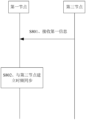
- FIG. 3 is one of the schematic flowcharts of the first communication method provided by the embodiment of the present application.
- FIG. 4 is the second schematic flow diagram of the first communication method provided by the embodiment of the present application.
- FIG. 5 is a schematic diagram of a set of synchronous communication domains provided by an embodiment of the present application.
- FIG. 6 is the third schematic flow diagram of the first communication method provided by the embodiment of the present application.
- FIG. 7 is one of the time-frequency synchronization schematic diagrams of the first node provided by the embodiment of the present application.
- FIG. 8 is the second schematic flow diagram of the second communication method provided by the embodiment of the present application.
- Fig. 9 is a schematic structural diagram of the device provided by the embodiment of the present application.
- FIG. 10 is another schematic structural diagram of the device provided by the embodiment of the present application.
- Time-frequency synchronization includes time synchronization and frequency synchronization.
- Time synchronization refers to adjusting the clock values of different nodes to a certain degree of accuracy or compliance, or adjusting the error of the initial moment of transmission of time units of different nodes within a certain range.
- a unit of a time unit may be a superframe, a radio frame (radio frame), a symbol (symbol), or other time units.
- a super frame is a time unit composed of multiple radio frames
- a radio frame is a time unit smaller than a super frame
- a symbol is a time unit smaller than a radio frame.
- each superframe contains 48 wireless frames
- the length of each superframe is 1ms.
- a superframe includes 48 radio frames, and numbers of the 48 radio frames are radio frame #0 to radio frame #47 in sequence.
- 10 symbols are included in each radio frame. Among the 10 symbols, 4 symbols are used for downlink, 3 symbols are used for uplink, 2 symbols are used as a guard interval (gap, GAP), and 1 symbol is used as a flexible symbol. This flexible symbol can be used for uplink transmission or can be used There is no limitation on downlink transmission or other transmission.
- uplink usually refers to the direction in which a terminal (terminal, T) node sends data or information to a management (grant, G) node, which can be represented by "T”.
- Downlink usually refers to the direction in which node G sends data or information to node T, which can be represented by "G”. Since in the vehicle-mounted wireless short-distance communication system, there are usually communication requirements between different T nodes or different G nodes, the communication between different T nodes or different G nodes may occupy the above-mentioned flexible symbols. In the above Figure 1, the flexible symbol is represented as special grant (SG).
- SG special grant
- the G node and T node are just a distinction for node functions, and do not limit specific node names.
- it may be a communication node in the Starlight short-distance communication standard, or a communication node in a short-distance communication system such as Bluetooth.
- the present application does not specifically limit the type of the communication system.
- Frequency synchronization means that the carrier frequency error of different nodes is kept within a certain range.
- the carrier frequency error of different nodes can refer to the relative/absolute error between the actual frequency of the node and the expected frequency, or the relative/absolute error of the actual frequency between different nodes. wait.
- Frequency synchronization may also be referred to as frequency quadrature. For example, a subcarrier frequency used by node 1 is f0, and a subcarrier frequency used by node 2 is f1.
- the constraints can be determined according to factors such as system anti-interference capability and service characteristics , the frequencies adopted by node 1 and node 2 are considered to be orthogonal, otherwise they are considered not to be orthogonal.
- the T node needs to establish time synchronization with the G node, then the T node needs to obtain the start position and end position of the symbol sent by the G node, and its duration is consistent with the understanding of the G node, and the T node and the G node Establish time synchronization.
- the T node needs to obtain the carrier frequency of the G node, so that the error between the carrier frequency of the T node and the carrier frequency of the G node is kept within a certain range, and the T node and the G node establish frequency synchronization.
- the carrier frequency error between the T node and the G node may be 100 Hz.
- the first node may be understood as a node that needs to perform time-frequency synchronization.
- the first node may be a G node.
- the second node may be understood as a node used to replace the first node to measure synchronization information of nodes on the first channel.
- the second node may be a node in the same synchronization area as the first node.
- the third node may be understood as a node used for measurement by the second node on the first channel.
- the third node may be one or more nodes, which is not specifically limited in this embodiment of the present application.
- the measurement configuration information may be understood as information configured by the first node to the second node, and the information may be used to measure synchronization information of nodes in the first channel.
- first measurement configuration information may be used to indicate the first channel, the measurement target, the first period corresponding to the measurement resource, the duration of the measurement resource in the first period, the offset of the measurement resource in the first period, the measurement The initial time-domain position number of the resource, or the quantity of the measurement resource; the second measurement configuration information may be used to indicate to measure the synchronization information updated by the third node in the first channel.
- the first channel may be understood as a channel to be measured designated by the first node, and in some possible embodiments, the first channel may be characterized by its corresponding channel frequency.
- the measurement target may be understood as the type of information to be measured in the first channel.
- the measurement target includes one or more of the following: reference signal received power (received signal reference power, RSRP), reference signal reception quality (received signal reference quality, RSRQ), signal to interference plus noise ratio (signal-to-noise ratio, SINR), received signal strength indicator (received signal strength indicator, RSSI), synchronous communication domain set measurement, time adjustment measurement, or frequency adjustment measurement.
- a set of synchronous communication domains may also be referred to as a synchronization group, which may be understood as a set formed by establishing time-frequency synchronization of multiple first-type nodes.
- the first type of nodes may be G nodes and/or T nodes, which are not limited in this embodiment of the present application.
- the G1 node and the G2 node establish time-frequency synchronization, and the G1 node and the G2 node may form a set of synchronous communication domains.
- the G1 node and the T1 node establish time-frequency synchronization, and the G1 node and the T1 node may form a set of synchronous communication domains.
- the synchronous communication domain set measurement may be understood as measuring the synchronous communication domain set information to which the nodes in the first channel belong.
- the synchronous communication domain set information may be understood as the information of the synchronous communication domain set formed by establishing time-frequency synchronization between nodes in the first channel and other first-type nodes.
- the synchronous communication domain set information may include but not limited to one or more of the following: the topological relationship of the synchronous communication domain set, the priority information of the third node, the first node included in the synchronous communication domain set The number of nodes of the same type, or the synchronization state between the third node and other nodes of the first type except the third node in the set of synchronous communication domains.
- the first type of nodes may be understood as G nodes and/or T nodes, which are not specifically limited in this embodiment of the present application.
- the topological relationship of the synchronous communication domain set can be understood as the relationship between the root node and the parent node in the synchronous communication domain set, and the topological relationship can be represented by the node identifier.
- the root node is the first node in the synchronous communication domain set, and other nodes in the synchronous communication domain set directly or indirectly join the synchronous communication domain set through the root node.
- a synchronization path refers to a connected path passing from the root node to the current node. For example, the current node enters the synchronous communication domain set through the parent node, and the parent node enters the synchronous communication domain set through the root node, then the current node-parent node-root node forms a synchronous path.
- the priority information of the third node may be understood as the priority of establishing time-frequency synchronization between the first node and the third node.
- the synchronization state can be understood as the synchronization situation between the third node and other nodes of the first type except the third node in the set of synchronous communication domains.
- the synchronization communication domain set information includes node identifiers, synchronization status and synchronization direction.
- the node identifiers may specifically refer to the identifiers G1 to G5 in Table 1
- the synchronization state may be represented by a binary value "0" or "1”.
- the synchronization state of the G1 node is 1, which may specifically mean that the G1 node maintains time-frequency synchronization with the G1 node and the G2 node respectively, while the G1 node does not maintain direct time-frequency synchronization with the G3 node, the G4 node, and the G5 node.
- the synchronization direction may refer to the synchronization direction of each node.
- “1” means that Gx and Gy are time-frequency synchronized, such as G1->G2 is "1", which means that G1 and G2 are time-frequency synchronized, that is, the time frequency of G1 will be adjusted according to the time frequency of G2, and G2 will be The parent node of frequency synchronization, G1 is the child node of time frequency synchronization.
- “0” means that Gx does not perform time-frequency synchronization with Gy.
- G2->G1 is "0”, which means that G2 does not perform time-frequency synchronization with G1, that is, the time frequency of G2 will not be adjusted according to the time frequency of G1.
- the time-frequency synchronization in Table 1 is directional.
- G1 and G2 perform time-frequency synchronization, that is, the time-frequency of G1 is adjusted according to the time-frequency of G2, and the value of G1->G2 is "1".
- G2 does not perform time-frequency synchronization with G1, that is, the time-frequency of G2 is not adjusted according to the time-frequency of G1, and the value of G2->G1 is "0".
- a table is only a form of expression of a relationship. In specific implementation, it is not limited to only using a table, and any other method that can reflect corresponding information can be used in the implementation of the present application.
- the time adjustment measurement can be understood as measuring the time synchronization information of the nodes in the first channel.
- the time synchronization information may be understood as information related to time synchronization of the third node.
- the time synchronization information may include a first time offset between the third node and the first node.
- the first time offset can be understood as the degree of difference between the clock values of the first node and the third node at the first moment, or the error at the start moment of the transmission of the time unit of the first node and the third node.
- the time synchronization information may include the clock value of the third node at the first moment and/or the starting moment of transmission of the time unit of the third node.
- frequency adjustment measurement may be understood as measuring frequency synchronization information of nodes in the first channel.
- the frequency synchronization information may be understood as information related to frequency synchronization of the third node.
- the frequency synchronization information may include a first frequency offset between the third node and the first node.
- the first frequency deviation can be understood as the carrier frequency error between the first node and the third node at the first moment, and the carrier frequency error can be understood as the relative/absolute error of the actual frequency between the first node and the third node.
- the frequency synchronization information may include the carrier frequency of the third node.
- measurement resource can be understood as a time resource used by the second node to measure the synchronization information of the third node in the first channel, and the time unit of the time resource can be, for example, a superframe, a radio frame, a symbol or other time units.
- the duration of the measurement resource in the first period may be understood as the time unit occupied by the measurement resource in the first period.
- start time domain position number of the measurement resource may be understood as the number corresponding to the time resource indicating that the second node starts measuring, for example, may be the number indicating the superframe where the second node starts measuring.
- the "number of measurement resources” can be understood as the number of time units corresponding to the time resources used by the second node to measure the synchronization information of the third node in the first channel, for example, it can be a superframe, a radio frame, a symbol or other time units quantity.
- the synchronization information may be understood as information used to characterize the time-frequency synchronization of the third node.
- the synchronization information may also be referred to as measurement result information.
- the synchronization information may be used to indicate one or more items of time synchronization information, frequency synchronization information, synchronous communication domain set information, RSRP, RSRQ, SINR, or RSSI.
- time synchronization information, frequency synchronization information, and synchronous communication domain set information please refer to the previous description, which will not be repeated here.
- RSRP Resource Reference Signal
- RSRQ Radio Service Set
- SINR Signal-to-Network Reference Signal
- RSSI Signal-to-Network Reference Signal
- other parameters may also be used to characterize the signal reception strength of the second node for the information from the third node.
- the node identifier can be the node's media access control (media access control, MAC) address, or a part of the node's MAC address, for example, the first n digits, the last n digits, and the middle n digits of the node's MAC address, or the node's MAC address Arbitrary n bits in the address, the n bits may be continuous values or discontinuous values in the MAC address, etc., and are not limited. Wherein, the value of n is a positive integer greater than or equal to 1 and less than all the bits of the MAC address.
- the node ID can be an ID that identifies the identity of the node generated based on the MAC address of the node.
- the MAC address of the node is used to perform logical operations with preset characters, and the result of the operation is used as the ID of the node.
- Logical operations can include logical XOR, logical Addition and subtraction etc.
- the node identifier may be other identifiers or addresses that can identify the identity of the node, such as an index, address, etc. pre-allocated for the node.
- the node identification may be the identification of the communication domain where the node is located.
- the resources that the G node sends synchronization signals, broadcast information, G link control information, and resources that the G node can schedule and configure are called the resource set of the G node.
- the communication domain or the communication domain resources of the G node, the G node is called the G node of the communication domain.
- a communication domain generally includes one G node and at least one T node.
- the identifier of the communication domain may be equal to the identifier of the G node, or in other words, the identifier of the G node may be called the identifier of the communication domain where the G node is located.
- its node identifier can also be understood as the identifier (DomainID) of the communication domain where it is located.
- the first synchronization area can be understood as a set of synchronous communication domains formed by establishing time-frequency synchronization between the first node and the second type of node.
- the second type of nodes may be T nodes.
- Broadcasting is a way of disseminating information. It refers to the way a certain node in the network sends information. The range to which this information can spread is called the broadcast domain, and other nodes in the broadcast domain can receive the information. Information sent in a broadcast manner may be called broadcast information, including but not limited to broadcast channel and/or system information.
- unicast messages are messages communicated over a network between a single sender and a single receiver.
- the multicast message is that the sender sends the message to multiple receivers in a specified group.
- At least one item (piece) of a, b, or c can represent: a, b, c, a-b, a-c, b-c, or a-b-c, where a, b, c can be single or multiple .
- Each communication domain includes a group of communication nodes with communication relationship: one G node and at least one T node.
- the G node manages the time-frequency resources of the communication domain, and has the function of scheduling resources for the communication link between the T nodes.
- Nodes that do not belong to the communication domain can be referred to as external nodes (including nodes that have not joined the communication domain and nodes that have joined the communication domain and then exited the communication domain).
- External nodes can be transformed into T nodes of the communication domain through the process of joining the communication domain. node.
- an external node When an external node joins the communication domain, it must first synchronize time and frequency with the communication domain, and obtain system information such as resource configuration and supported features of the communication domain.
- the T node In each communication domain, the T node can maintain time-frequency synchronization with its corresponding G node, and this application does not limit the synchronization mode between the T node and the G node.
- FIG. 2 shows a possible application scenario of this embodiment of the present application.
- FIG. 2 shows a schematic diagram of a topology relationship of an in-vehicle communication link.
- there are three communication domains in a specific area for example, a smart car cockpit), which are respectively a first communication domain, a second communication domain and a third communication domain.
- the mobile phone serves as the G node
- the headset and the wearable device serve as the T node.
- the car and machine serve as G nodes
- microphones, speakers, and mobile phones serve as T nodes.
- the keyless entry and start system serves as the G node
- the mobile phone key and car key serve as the T node.
- time-frequency synchronization needs to be maintained among the three G nodes of the mobile phone, car machine, and keyless entry and start system.
- the short-distance wireless system includes at least one G node, and each G node accesses at least one T node.
- the G node can be regarded as the creator of a wireless network, and is an intermediate node of the network.
- the function of the G node is similar to a base station or a wireless fidelity access point (wireless fidelity access apoint, WIFI AP).
- T nodes can be considered as terminals connected to wireless networks, such as mobile phones, headsets, notebooks and computers.
- the mobile phone can be used as a G node, and the headset belonging to the same user as the mobile phone can be used as a T node.
- multiple G nodes can be arranged in the conference room, and other conference rooms
- a terminal device may serve as a T node, such as a wireless speaker or a mobile phone, and access any one of the above-mentioned multiple G nodes.
- multiple G nodes are included in the smart car.
- the terminal device needs to maintain time-frequency synchronization with the original multiple G nodes in the above-mentioned smart car.
- the embodiments of the present application provide two communication methods.
- the first communication method can be applied to the first node and the second node, in this method: the first node can send the first measurement configuration information to the second node, and the first measurement configuration information is used to indicate the measurement of the first channel Synchronization information of the third node; then the second node can obtain the synchronization information, the first node can receive synchronization information from the second node, and the synchronization information is used to indicate the time synchronization information, frequency synchronization information, and One or more of synchronous communication domain set information, RSRP reference signal received power, RSRQ reference signal received quality, SINR signal to interference plus noise ratio, or RSSI received signal strength indication.
- the above-mentioned first communication method can be applied to the scenario where the first node has established a business, so through the method of the embodiment of this application, the first node can obtain the synchronization of the third node in the first channel through the second node
- the information can be used to obtain the synchronization information of the nodes in the first channel without affecting the service of the first node, so as to achieve time-frequency synchronization of multiple nodes.
- the second communication method can be applied to the first node, the method includes: receiving first information from the third node, the first information is used to indicate the time synchronization information, frequency synchronization information, and synchronous communication of the third node One or more of domain set information, RSRP, RSRQ, SINR, or RSSI; establish time-frequency synchronization with the third node.
- the above-mentioned second communication method can be applied to a scenario where the first node has just started up and has not yet established a service, or a scenario when the service of the first node is in an idle state (for example, in the early morning or when no terminal node is currently connected).
- the first node can directly obtain the synchronization information of the third node from the third node, and establish time-frequency synchronization with the third node, effectively improving the efficiency of establishing time-frequency synchronization of the first node.
- FIG. 3 shows a schematic flowchart of the first communication method provided by the embodiment of the present application.
- the establishment of time-frequency synchronization by the first node in the short-distance communication system is taken as an example for description.
- the node used to replace the first node to measure the synchronization information of the nodes on the first channel is called the second node
- the node that establishes time-frequency synchronization with the first node is called the third node.
- the first node and the third node may be G nodes in the wireless short-distance communication system
- the second node may be T nodes in the wireless short-distance communication system.
- the method includes the following steps:
- the first node sends first measurement configuration information to the second node.
- the second node receives the first measurement configuration information.
- the first measurement configuration information is used to indicate to measure the synchronization information of the third node in the first channel, and then the second node can measure the synchronization information of the third node in the first channel according to the first measurement configuration information.
- the second node may be one or more nodes, which is not specifically limited in this embodiment of the present application.
- the second node may be a second type of node in the first synchronization area to which the first node belongs.
- the second type of nodes may be all T nodes or terminal nodes in the first synchronization area.
- the first node may determine the second node according to the service priority and/or load information of the second type of nodes in the first synchronization area.
- the service priority of the second type of node may be characterized by the type of service currently being performed by the second type of node (for example, video service, voice service, etc.).
- the service priority of a node corresponds to the service type of the node.
- the load information of the second type of nodes may be determined by the number of tasks currently processed by the second type of nodes.
- the first node determines that there are many situations in the second node, including but not limited to the following situations:
- the first node may determine the second node according to the service priority of the second type of nodes in the first synchronization area.
- Example 1 the second type of nodes in the first synchronization area take node T1 and node T2 as examples, wherein, the service type of node T1 is video service, and the service type of node T2 is voice service, then the service priority of node T1 is higher than High, the service priority of the node T2 is low, the first node may determine the node T2 as the second node, and measure the synchronization information of the third node in the first channel through the node T2.
- Example 2 the second type of nodes in the first synchronization area take node T1, node T2 and node T3 as examples, wherein, the service type of node T1 is video service, and the service type of node T2 and node T3 is voice service, then the node The service priority of T1 is higher, and the service priority of nodes T2 and T3 is lower.
- the first node can determine the node T2 and node T3 as the second node, and measure the third node in the first channel through the node T2 and node T3. Node synchronization information.
- the first node may determine the second node according to the load information of the second type of nodes in the first synchronization area.
- the second type of nodes in the first synchronization area take node T1 and node T2 as examples, wherein, the number of tasks currently processed by node T1 is 10, and the number of tasks currently processed by node T2 is 1, then node T1
- the load of node T2 is relatively high, and the load of node T2 is relatively low.
- the first node may determine node T2 as the second node, and use node T2 to measure the synchronization information of the third node in the first channel.
- the first node may determine the second node according to the service priority and load information of the second type of nodes in the first synchronization area.
- the first node can filter out the second node suitable for synchronization information measurement according to the service priority and/or load information of the second type of node, which can effectively avoid the synchronization information measurement from affecting some second nodes.
- the business of similar nodes will be affected, thereby effectively improving user experience.
- the above-mentioned first channel may be understood as a channel to be measured designated by the first node, and in some possible embodiments, the first channel may be characterized by its corresponding channel frequency. That is to say, the first measurement configuration information may indicate the first channel to be measured by indicating the channel frequency of the first channel.
- the above-mentioned first measurement configuration information may also be used to indicate the measurement target, the first period corresponding to the measurement resource, the duration of the measurement resource in the first period, and the duration of the measurement resource in the first period.
- the measurement target may be understood as the type of information to be measured in the first channel.
- the measurement target includes but not limited to one or more of the following: RSRP, RSRQ, SINR, RSSI, synchronous communication domain set measurement, time adjustment measurement, or frequency adjustment measurement.
- one or more items of RSRP, RSRQ, SINR, or RSSI are used to characterize the signal reception strength of the second node for the information from the third node.
- the signal reception strength of the second node for the information from the third node may also be characterized by other parameters.
- the aforementioned set of synchronous communication domains may also be referred to as a synchronous group, which may be understood as a set formed by establishing time-frequency synchronization of multiple first-type nodes.
- the first type of nodes may be G nodes and/or T nodes, which are not limited in this embodiment of the present application.
- the G1 node and the G2 node establish time-frequency synchronization, and the G1 node and the G2 node may form a set of synchronous communication domains.
- the G1 node and the T1 node establish time-frequency synchronization, and the G1 node and the T1 node may form a set of synchronous communication domains.
- the synchronous communication domain set measurement may be understood as measuring the synchronous communication domain set information to which the nodes in the first channel belong.
- the time adjustment measurement may be understood as measuring time synchronization information of nodes in the first channel, and the time synchronization information may be understood as information related to time synchronization of the third node.
- frequency adjustment measurement may be understood as measuring frequency synchronization information of a node in the first channel, and the frequency synchronization information may be understood as information related to frequency synchronization of a third node.
- Example 1 if the measurement target includes synchronous communication domain set measurement, after receiving the first measurement configuration information, the second node may measure the synchronous communication domain set to which the third node in the first channel belongs.
- the measurement target includes time adjustment measurement
- the second node may measure the time synchronization information of the third node in the first channel
- the time synchronization information of the third node may include, for example, the first The first time offset between the three nodes and the first node
- the first time offset can be understood as the difference between the clock values of the first node and the third node at the first moment, or can be understood as the first node and the error of the start moment of the transmission of the time unit of the third node.
- the time synchronization information may include the clock value of the third node and/or the start moment of transmission of the time unit of the third node.
- Example 3 if the measurement target includes frequency adjustment measurement, after the second node receives the first measurement configuration information, it may measure the frequency synchronization information of the third node in the first channel, and the frequency synchronization information of the third node may include, for example, the first The first frequency deviation between the three nodes and the first node, the first frequency deviation can be understood as the carrier frequency error between the first node and the third node at the first moment, and the carrier frequency error can be understood as the The relative/absolute error of the actual frequency between the three nodes.
- the frequency synchronization information may include the carrier frequency of the third node.
- the measurement target includes RSRP, RSRQ, SINR and RSSI
- the second node after the second node receives the first measurement configuration information, it can measure the signal strength of the second node for the information from the third node in the first channel, the signal Strength can be characterized by RSRP, RSRQ, SINR and RSSI.
- Example 5 if the measurement target includes synchronous communication domain set measurement, time adjustment measurement and frequency adjustment measurement, after the second node receives the first measurement configuration information, it can measure the synchronous communication domain set information of the third node in the first channel , time synchronization information and frequency synchronization information.
- Example 6 if the measurement target includes RSRP, RSRQ, SINR, RSSI, synchronous communication domain set measurement, time adjustment measurement, and frequency adjustment measurement, after the second node receives the first measurement configuration information, it can measure the first channel. Synchronization communication domain set information, time synchronization information and frequency synchronization information of the third node, and measuring the signal strength of the second node for the information from the third node in the first channel, the signal strength can be passed through RSRP, RSRQ, SINR and RSSI to characterize.
- measurement resource can be understood as the time resource used by the second node to measure the synchronization information of the third node in the first channel, and the time unit of the time resource can be, for example, a superframe, a radio frame (radio frame), symbol (symbol), or other time units.
- the "first period corresponding to the measurement resource” may be multiple consecutive time units.
- the duration of the measurement resource in the first period may be understood as the time unit occupied by the measurement resource in the first period.
- the “offset of the measurement resource in the first period” may be understood as an adjustable range of the time unit occupied by the measurement resource in the first period.
- the “start time domain position number of the measurement resource” may be understood as the number corresponding to the time resource indicating that the second node starts measuring, for example, may be the number indicating the superframe where the second node starts measuring.
- the "number of measurement resources” can be understood as the number of time units corresponding to the time resources used by the second node to measure the synchronization information of the third node in the first channel, for example, it can be a superframe, a radio frame, a symbol or other time units quantity.
- the first cycle corresponding to the measurement resource may be 50 consecutive superframes, and the duration of the measurement resource in the first cycle may be 20 superframes in the 50 consecutive superframes.
- the offset within one period may be 10 superframes, the starting time domain position number of the measurement resource may be the number of superframe 10 in 50 consecutive superframes, and the number of measurement resources may be 20.
- the synchronization process of the first node may be triggered by a first event, or periodically.
- the process of the first node sending the first measurement configuration information to the second node may be: in response to detecting the first event, sending the first measurement configuration information to the second node; wherein, the first Events include but are not limited to one or more of the following: the first node is turned on, the communication quality of the communication system to which the first node belongs is lower than the preset standard, the software module of the first node is started according to the preset configuration, or the first node is in A state that is not synchronized with any nodes.
- a specific event can be used to trigger the first node to send the first measurement configuration information to the second node, so that the time-frequency synchronization of the first node meets the service requirements of the first node and does not affect the service of the first node. Influence.
- the process of the first node sending the first measurement configuration information to the second node may be: the first node sends the first measurement configuration information to the second node after reaching the start time domain position of the first period configuration information.
- the first node periodically sends the first measurement configuration information to the second node, so that the time-frequency synchronization of the first node is more reasonable.
- the second node may be one or more nodes.
- the second node is multiple nodes, and the first node may send the first measurement configuration information to the second node in a multicast or unicast manner.
- the first measurement configuration information may be sent in a first period.
- the first measurement configuration information may be carried in a system message.
- the second node when the second node is one node, the first node may send the first measurement configuration information to the second node in a unicast manner.
- the second node acquires the synchronization information.
- step S302 specifically includes:
- the second node may receive the broadcast information of the third node.
- the second node determines the synchronization information according to the broadcast information.
- the broadcast information may contain various information, and the second node may select the information corresponding to the measurement target from the broadcast information as the synchronization information of the third node according to the type of the measurement target indicated by the first measurement configuration information.
- Example 1 if the measurement target indicated by the first measurement configuration information includes synchronous communication domain set measurement and time adjustment measurement, and the broadcast information received by the second node from the third node includes synchronous communication domain set information and time synchronization information, then The second node uses the synchronous communication domain set information and time synchronization information of the third node as synchronization information.
- Example 2 if the measurement target indicated by the first measurement configuration information includes frequency adjustment measurement, and the broadcast information received by the second node from the third node includes synchronous communication domain set information, time synchronization information and frequency synchronization information, then the second The node uses the frequency synchronization information of the third node as synchronization information.
- Example 3 if the measurement target indicated by the first measurement configuration information includes frequency adjustment measurement, the broadcast information received by the second node from the third node includes synchronous communication domain set information, time synchronization information and frequency synchronization information, but the frequency If the synchronization information only includes the carrier frequency of the third node, the second node may determine the frequency adjustment information according to the error between the carrier frequency of the third node and the carrier frequency of the second node, and determine the frequency adjustment information as synchronization information.
- the second node may receive the broadcast information of the third node, and directly use the broadcast information as the synchronization information of the third node.
- the broadcast received by the second node from the third node includes RSRP, RSRQ, SINR, RSSI, synchronous communication domain set information, time synchronization information and frequency synchronization information, and the second node uses the broadcast information of the third node as the synchronization information.
- the second node sends the synchronization information to the first node.
- the first node receives the synchronization information from the second node.
- the above synchronization information is used to indicate the time synchronization information, frequency synchronization information, synchronous communication domain set information, RSRP reference signal received power, RSRQ reference signal received quality, SINR signal to interference plus noise ratio, or RSSI received signal of the third node One or more of the strength indications.
- the synchronous communication domain set information may be understood as the information of the synchronous communication domain set formed by establishing time-frequency synchronization between nodes in the first channel and other first-type nodes.
- the synchronous communication domain set information may include but not limited to one or more of the following: the topological relationship of the synchronous communication domain set, the priority information of the third node, the first node included in the synchronous communication domain set The number of nodes of the same type, or the synchronization state between the third node and other nodes of the first type except the third node in the set of synchronous communication domains.
- the first type of nodes please refer to the previous section, and will not repeat them here.
- the topological relationship of the synchronous communication domain set can be understood as the relationship between the root node and the parent node in the synchronous communication domain set, and the topological relationship can be represented by a node identifier.
- the root node is the first node in the synchronous communication domain set, and other nodes in the synchronous communication domain set directly or indirectly join the synchronous communication domain set through the root node.
- a synchronization path refers to a connected path passing from the root node to the current node. For example, the current node enters the synchronous communication domain set through the parent node, and the parent node enters the synchronous communication domain set through the root node, then the current node-parent node-root node forms a synchronous path.
- the priority information of the third node may be understood as the priority of establishing time-frequency synchronization between the first node and the third node.
- the priority may be indicated by the sequence of nodes on the synchronization path in the set of synchronization communication domains, the position of nodes or the distance between the current node and the root node.
- the synchronization state can be understood as a synchronization situation between the third node and other nodes of the first type except the third node in the set of synchronous communication domains.
- FIG. 5 shows a schematic diagram of a topological relationship of a set of synchronous communication domains, wherein node 1 is the root node, node 2 and node 3 are parent nodes, and the third node is node 4 as an example , node 4 has child node C and child node D; the synchronization path of node 4 is node 4-node 3-node 2-node 1, correspondingly, the priority of node 4 is lower than that of node 3, and the priority of node 3 Lower than the priority of node 2, the priority of node 2 is lower than the priority of node 1, and the synchronization state of node 4 and other nodes in the communication domain set where it is located is directly or directly with node 3, node 2 and node 1 through the synchronization path Time-frequency synchronization is established indirectly.
- time synchronization information and the frequency synchronization information please refer to the relevant description above, which will not be repeated here.
- the first node can obtain the synchronization information of the third node on the first channel through the second node, and can obtain the synchronization information without affecting the service of the first node. Synchronization information of nodes in the first channel, so as to achieve time-frequency synchronization of multiple nodes.
- the above-mentioned first communication method also includes the following steps:
- the first node establishes time-frequency synchronization with the third node.
- time-frequency synchronization includes time synchronization and frequency synchronization.
- the time synchronization information in the synchronization information includes a first time offset between the third node and the first node, and the first node may adjust the clock value of the first node based on the first time offset , so that the difference between the clock values of the first node and the third node at the first moment is within the first preset range; or, the first node can adjust the time unit of the first node based on the first time deviation The starting moment of the transmission, so that the error of the starting moment of the transmission of the time unit of the first node and the third node is within the second preset range.
- the first preset range is different from the second preset range.
- the time synchronization information in the above synchronization information includes the clock value of the third node at the first moment and/or the starting moment of the transmission of the time unit of the third node, and the first node may be based on
- the time synchronization information determines the first time offset between the third node and the first node, and adjusts the clock value of the first node based on the first time offset, so that the first node and the third node at the first moment
- the degree of difference between the clock values is within a first preset range; or, the first node may adjust the starting moment of the transmission of the time unit of the first node based on the first time deviation, so that the first node and the third node
- the error of the start moment of the transmission of the time unit is within the second preset range.
- the first preset range is different from the second preset range.
- the frequency synchronization information in the synchronization information includes a first frequency deviation between the third node and the first node, and the first node may adjust the carrier frequency of the first node based on the first frequency deviation , so that the error between the carrier frequencies of the first node and the third node at the first moment is within a third preset range.
- the frequency synchronization information in the above synchronization information includes the carrier frequency of the third node at the first moment, and the first node may determine the frequency between the third node and the first node based on the frequency synchronization information. and adjusting the carrier frequency of the first node based on the first frequency deviation, so that the error between the carrier frequencies of the first node and the third node at the first moment is within a third preset range.
- the first node sends second measurement configuration information to the second node.
- the second node receives second measurement configuration information.
- the second measurement configuration information is used to indicate to measure the synchronization information updated by the third node;
- the first node may send the second measurement configuration information to the second node in a multicast or unicast manner; when the second node is one node, the first node may Send the second measurement configuration information to the second node in a unicast manner.
- the second node acquires the synchronization information updated by the third node.
- the second node sends the updated synchronization information to the first node.
- the first node receives the updated synchronization information.
- the updated synchronization information is used to indicate the second time offset and/or the second frequency offset between the third node and the first node.
- the second time offset can be understood as the degree of difference between the clock values of the first node and the third node at the second moment, or can be understood as the difference between the starting moment of the transmission of the time unit of the first node and the third node Error;
- the second frequency deviation can be understood as the carrier frequency error between the first node and the third node at the second moment.
- the first node may re-establish time-frequency synchronization with the third node based on the updated synchronization information.
- the first node can obtain the updated synchronization information of the third node again through the second node, and realize the synchronization tracking of the third node, so that the time-frequency synchronization between the first node and the third node is more accurate.
- the third node is used as an example to describe the process of establishing time-frequency synchronization between the first node and the third node. Taking the third node as multiple nodes as an example, the process of establishing time-frequency synchronization between the first node and the third node is introduced below.
- the first node may select a fourth node from the multiple third nodes, and establish time-frequency synchronization with the fourth node.
- the first node selects the fourth node from multiple third nodes in many situations, including but not limited to the following situations:
- Case 1 The first node considers the priorities of multiple third nodes, and the first node may use the node with the highest priority among the multiple third nodes as the fourth node.
- priorities of different nodes may be preset.
- the priority can be directly configured for each node.
- priority can also be configured indirectly for each node.
- a synchronization sequence is usually configured for each G node, and the synchronization sequence is used for time-frequency synchronization among different nodes.
- each node can determine its own priority through the synchronization sequence configured for it.
- the corresponding relationship between the synchronization sequence and the priority can be set in advance, and after the terminal device obtains the synchronization sequence configured for it, it can determine the priority of the node itself according to the synchronization sequence. For example, if the synchronization sequence pre-configured for the node G1 is a synchronization sequence A, and the priority corresponding to the synchronization sequence A is A, then the priority of the node G1 may be A.
- the priority may be indicated by the sequence of nodes on the synchronization path in the synchronization area, the position of the nodes, or the distance between the current node and the root node.
- the synchronization path refers to the connection path from the root node to the current node.
- the current node enters the synchronization area through the parent node, and the parent node enters the synchronization area through the root node, then the current node-parent node-root node forms the synchronization path, so in this example, the priority of the root node can be identified as 0, In the synchronization area and the synchronization path, the root node has the highest priority, then the priority of the above-mentioned parent node is 1 (or in other words, the distance from the root node is 1), second only to the root node, and the current node's The priority is 2 (or, the distance from the root node is 2), second to the parent node.
- numbers such as 0 and 1 are not limited to be used for identification, and any information that can reflect the size of the priority can be used for identification of the priority. Based on this example, if there are multiple synchronization paths in the synchronization area, multiple different nodes with the same distance from the root node may still have the same priority in different synchronization paths.
- each node can notify other nodes of its own priority.
- each node may explicitly indicate its own priority to other nodes.
- a node may send broadcast information or node information, and the broadcast information or node information includes the priority of the node.
- each node may implicitly indicate its own priority to other nodes.
- each node broadcasts and sends a synchronization signal for other nodes to synchronize time and frequency with itself.
- the synchronization signal includes a synchronization sequence, and the synchronization sequence can be used to implicitly indicate the priority of each node.
- the synchronous sequence has a corresponding relationship with the node priority
- the synchronous sequence is used to implicitly indicate the priority of the node as an example, which is not limited to the embodiment of the present application.
- the information corresponding to the node priority may also be other information, for example, the other information may be the root sequence of the synchronization sequence, that is, other information may also be used to implicitly indicate the priority of the node, such as the root sequence of the synchronization sequence.
- at least one node indicates its own priority to the first node, that is, the node information sent by at least one node includes the node priority.
- the first node may select a third node from the plurality of third nodes with the highest priority as the fourth node.
- the first preset rule may be randomly selecting a node, or based on signal strengths of multiple third nodes and/or the number of nodes included in the synchronization area to which they belong.
- the multiple third nodes take node A, node B, and node C as examples.
- the priority of node A is 2, the priorities of nodes B and C are both 1, and priority 1 is higher than priority 2.
- the first node may select a node among the above-mentioned node B and node C based on the first preset rule as the second node, and so on.
- Case 2 The first node considers the number of nodes included in the communication domain set to which the third node belongs, and determines the third node with the largest number of nodes included in the communication domain set as the fourth node.
- the multiple third nodes take node A, node B and node C as examples, the number of nodes included in the communication domain set A to which node A belongs is N1, and the number of nodes included in the communication domain set B to which node B belongs The number is N2, and the number of nodes included in the communication domain set C to which node C belongs is N3.
- N1, N2, and N3 are all positive integers. If the value of N3 is greater than N1 and N2, the first node may select node C as the fourth node.
- the first node needs to select a node from node A and node B as the fourth node.
- the first node may select a node among the nodes that include the largest number of nodes in the communication domain set to which it belongs as the fourth node.
- the second preset rule may be randomly selecting a node, or based on signal strengths and/or priorities of multiple third nodes.
- Case 3 The first node considers the signal strengths of multiple third nodes, and the first node may use the node with the highest signal strength among the multiple third nodes as the fourth node.
- the first node may select the node with the highest signal strength of node information, broadcast information, or other channels or signals among the plurality of third nodes as the fourth node.
- the signal strength of the node information may specifically refer to the signal strength of the node information received by the first node from other nodes
- the signal strength of the broadcast information may specifically refer to the signal strength of the broadcast information received by the first node.
- the broadcast information may be a synchronization signal.
- the received signal strength of the first node radio frequency transmit power+antenna gain at the transmitting end ⁇ path loss ⁇ attenuation of obstacles+antenna end at the receiving end.
- Received signal strength can be measured in decibel (dB) or decibel milliwatt (decibel relative to one milliwatt, dBm).
- dB decibel
- dBm decibel milliwatt
- multiple third nodes take Node A and Node B as examples, the first node receives the signal strength of the broadcast information of Node A, that is, the received signal strength is 100 dBm, and receives the signal strength of the broadcast information of Node B, that is, receives If the signal strength is 101 dBm, the first node may select node B as the fourth node.
- the first node may select one node among the above multiple nodes as the fourth node based on the third preset rule.
- the third preset rule may be to randomly select a node, or based on the priorities of multiple nodes and/or the number of nodes in the set of synchronous communication domains to which they belong.
- the first node may also send synchronization adjustment information between the first node and the third node, and the synchronization adjustment information is used to indicate the second type of nodes in the first synchronization area Establish time-frequency synchronization with the third node.
- the second type of nodes may be one or more nodes. Therefore, when the second node is multiple nodes, the first node may send the synchronization adjustment information to the second type of nodes in a broadcast or multicast manner. When the second node is one node, the first node may send the synchronization adjustment information to the second type of node in a unicast manner.
- the time synchronization information in the synchronization information includes time adjustment information (for example, the first time offset), and the frequency synchronization information in the synchronization information includes frequency adjustment information (for example, the first time offset). frequency deviation), the first node may send the synchronization information to the second type of node as the synchronization adjustment information and the time when the adjustment takes effect.
- the time synchronization information in the synchronization information includes time information of the third node (for example, the clock value at the first moment), and the frequency synchronization information in the synchronization information includes frequency information of the three nodes (for example, , carrier frequency), the first node can further determine the frequency adjustment information (for example, the first frequency offset), the time adjustment information (for example, the first time offset) and the time when the synchronization adjustment takes effect according to the synchronization information, and store the frequency adjustment information , the time adjustment information and the time when the synchronization adjustment takes effect are sent to the second type of nodes as the synchronization adjustment information.
- the first node sends synchronization adjustment information to the second-type nodes in the first synchronization area to which it belongs, so that the second-type nodes can establish time-frequency synchronization with the third node, further realizing time-frequency synchronization among multiple nodes. frequency synchronization.
- the first node is G1 node as an example
- the third node is G2 node as an example
- the second type of nodes is T1 node and T2 node as an example.
- the G1 node, the T1 node and the T2 node have already established the time-frequency synchronization, forming a first synchronization area.
- the G1 node After the G1 node receives the synchronization information from the G2 node, if the time synchronization information in the synchronization information includes time adjustment information, and the frequency synchronization information in the synchronization information includes frequency adjustment information, the G1 node can use the synchronization information and the adjustment effective time as The synchronization adjustment information A is sent to the T1 node and the T2 node.
- the G1 node can further determine the frequency adjustment information and time adjustment information according to the synchronization information, and combine the frequency adjustment information, time adjustment
- the information and the adjustment effective time are sent as synchronous adjustment information A to the T1 node and the T2 node.
- the T1 node and the T2 node may establish time-frequency synchronization with the G2 node according to the synchronization adjustment information A.
- FIG. 8 shows a schematic flowchart of a second communication method provided by an embodiment of the present application.
- the establishment of time-frequency synchronization by the first node in the short-distance communication system is taken as an example for description.
- the first node and the third node may be G nodes in the wireless short-distance communication system.
- the method includes the following steps:
- the first node receives first information from a third node.
- the first information is used to indicate one or more of time synchronization information, frequency synchronization information, synchronous communication domain set information, RSRP, RSRQ, SINR, or RSSI of the third node; and the third node Establish time-frequency synchronization.
- the foregoing first information is carried in a broadcast message, a unicast message, or a multicast message. That is to say, the third node may send synchronization information to the first node in various ways.
- the first node establishes time-frequency synchronization with the third node.
- the communication method shown in FIG. 8 is applicable to scenarios where the first node has just started up and has not yet established a service, or when the service of the first node is in an idle state (for example, in the early morning or when no terminal node is currently connected). Therefore, through the method of the embodiment of the present application, the first node can directly obtain the synchronization information of the third node from the third node, and establish time-frequency synchronization with the third node, effectively improving the efficiency of establishing time-frequency synchronization of the first node.
- the first node may receive first information from multiple third nodes, and the first node may be in this
- the fourth node is selected from the plurality of third nodes, and time-frequency synchronization is established with the fourth node.
- the specific process please refer to the relevant description above, which will not be repeated here.
- Fig. 9 is a schematic block diagram of an apparatus 900 provided by an embodiment of the present application, which is used to realize the functions of the first node or the second node in the above method embodiments.
- the device may be a software module or a system on a chip.
- the chip may consist of chips, or may include chips and other discrete devices.
- the apparatus 900 includes a processing unit 901 and a communication unit 902 .
- the communication unit 902 is used to communicate with other devices, and may also be called a communication interface, a transceiver unit, or an input/output interface.
- the device 900 may be the first node, or a chip or a circuit configured in the first node.
- the processing unit 901 is configured to perform processing-related operations of the first node in the first method embodiment above
- the communication unit 902 is configured to perform transceiving-related operations of the first node in the first method embodiment above.
- the communication unit 902 can be used to receive and send the first measurement configuration information to the second node, and the first measurement configuration information is used to indicate the measurement of the first node.
- Synchronization information of a third node in a channel receiving the synchronization information from the second node, where the synchronization information is used to indicate time synchronization information, frequency synchronization information, synchronous communication domain set information of the third node, One or more of RSRP, RSRQ, SINR, or RSSI.
- the time synchronization information includes a first time offset between the third node and the first node.
- the frequency synchronization information includes a first frequency offset between the third node and the first node.
- the synchronous communication domain set information includes one or more of the following: the topological relationship of the synchronous communication domain set, the priority information of the third node, the first node included in the synchronous communication domain set The number of nodes of the same type, or the synchronization state between the third node and other nodes of the first type except the third node in the set of synchronous communication domains.
- the first measurement configuration information is further used to indicate the measurement target, the first period corresponding to the measurement resource, the duration of the measurement resource in the first period, the duration of the measurement resource The offset within the first period, the starting time domain position number of the measurement resource, or the quantity of the measurement resource; wherein, the measurement target includes one or more of the following: the reference signal Received power, the reference signal received quality, the signal-to-interference-plus-noise ratio, the received signal strength indication, the synchronous communication domain set measurement, time adjustment measurement, or frequency adjustment measurement; wherein the measurement resource is A time resource used for measuring the first channel.
- the synchronization information is used for the first node to establish time-frequency synchronization with the third node.
- the communication unit 902 may also be configured to send synchronization adjustment information between the first node and the third node, where the synchronization adjustment information is used to indicate that the second type of nodes in the first synchronization area and the The third node establishes time-frequency synchronization; wherein, the first synchronization area is a synchronization area to which the first node belongs.
- the communication unit 902 may also be configured to send second measurement configuration information to the second node after the first node establishes time-frequency synchronization with the third node, and the second measurement configuration information uses Instructing to measure the updated synchronization information of the third node; receiving the updated synchronization information from the second node, the updated synchronization information used to indicate the synchronization between the third node and the first node A second time offset and/or a second frequency offset.
- the processing unit 901 may determine the second node according to service priorities and/or load information of nodes of the second type in the first synchronization area.
- the communication unit 902 when configured to send the first measurement configuration information to the second node, it is specifically configured to: send the first event to the second node in response to the processing unit 901 detecting the first event.
- the first measurement configuration information wherein, the first event includes one or more of the following: the first node is turned on, the communication quality of the communication system to which the first node belongs is lower than a preset standard, and the first The software module of the node is started according to the preset configuration, or the first node is in a state of not being synchronized with any node; or, the initial time domain position of the first cycle is reached, and the second node is sent the First measurement configuration information.
- the device 900 may be the second node, or a chip or a circuit configured in the second node.
- the processing unit 901 is configured to execute the processing-related operations of the second node in the first method embodiment above
- the communication unit 902 is configured to execute the transceiving-related operations of the second node in the first method embodiment above.
- the communication unit 902 is configured to receive a first measurement configuration device, where the first measurement configuration information is used to measure synchronization information of a third node in the first channel; to obtain the synchronization information, the The synchronization information is used to indicate one or more of time synchronization information, frequency synchronization information, synchronous communication domain set information, RSRP, RSRQ, SINR, or RSSI of the third node; sending the synchronization information to the first node information.
- the communication unit 902 is further configured to receive synchronization adjustment information between the first node and the third node, where the synchronization adjustment information is used for the second node and the third node.
- Three nodes establish time-frequency synchronization; wherein, the second node and the first node belong to a first synchronization area.
- the communication unit 902 is further configured to receive second measurement configuration information, where the second measurement configuration information is used to measure updated synchronization information of the third node; acquire the updated synchronization information; sending the updated synchronization information to the first node, where the updated synchronization information is used to indicate a second time offset and/or a second frequency offset between the third node and the first node.
- the above-mentioned device 900 is used to realize the function of the first node in the second method embodiment above, and the device 900 may be the first node, or a chip or a circuit configured in the first node.
- the processing unit 901 is configured to perform processing-related operations of the first node in the method embodiment above
- the communication unit 902 is configured to perform transceiving-related operations of the first node in the second method embodiment above.
- the communication unit 902 is configured to receive first information from a third node, where the first information is used to indicate time synchronization information, frequency synchronization information, synchronous communication domain set information, RSRP, RSRQ, SINR, or RSSI of the third node One or more of the items; establishing time-frequency synchronization with the third node.
- the first information is carried in a broadcast message, a unicast message, or a multicast message. That is to say, the third node may send synchronization information to the first node in various ways.
- each functional unit may be integrated into one processor, or physically exist separately, or two or more units may be integrated into one unit.
- the above-mentioned integrated units can be implemented in the form of hardware or in the form of software functional units.
- FIG. 10 is a schematic diagram of a device 1000 provided by an embodiment of the present application.
- the device 1000 may be a first node or a second node, or a component of the first node or the second node, such as a chip or an integrated circuit wait.
- the apparatus 1000 can include at least one processor 1002 and a communication interface 1004 . Further, optionally, the device may further include at least one memory 1001 . Furthermore, optionally, a bus 1003 may also be included. Wherein, the memory 1001 , the processor 1002 and the communication interface 1004 are connected through a bus 1003 .
- the memory 1001 is used to provide a storage space, and data such as an operating system and computer programs can be stored in the storage space.
- Memory 1001 can be random access memory (random access memory, RAM), read-only memory (read-only memory, ROM), erasable programmable read-only memory (erasable programmable read only memory, EPROM), or portable read-only memory One or more combinations of memory (compact disc read-only memory, CD-ROM), etc.
- the processor 1002 is a module for performing arithmetic operations and/or logic operations, and specifically may be a central processing unit (central processing unit, CPU), a picture processor (graphics processing unit, GPU), a microprocessor (microprocessor unit, MPU), Application specific integrated circuit (ASIC), field programmable logic gate array (field programmable gate array, FPGA), complex programmable logic device (complex programmable logic device, CPLD), coprocessor (to assist the central processing unit to complete Corresponding processing and application), microcontroller unit (microcontroller unit, MCU) and other processing modules or a combination of more.
- CPU central processing unit
- CPU central processing unit
- MPU graphics processing unit
- ASIC application specific integrated circuit
- FPGA field programmable logic gate array
- FPGA field programmable gate array
- CPLD complex programmable logic device
- coprocessor to assist the central processing unit to complete Corresponding processing and application
- microcontroller unit microcontroller unit, MCU
- Communication interface 1004 may be used to provide information input or output to the at least one processor. And/or the communication interface can be used to receive data sent from the outside and/or send data to the outside, which can be a wired link interface such as an Ethernet cable, or a wireless link (Wi-Fi, Bluetooth, General wireless transmission, vehicle short-distance communication technology, etc.) interface.
- the communication interface 1004 may further include a transmitter (such as a radio frequency transmitter, an antenna, etc.) or a receiver coupled with the interface.
- the foregoing apparatus 1000 may be the first node or components in the first node in the first method embodiment above, such as a chip or an integrated circuit.
- the processor 1002 in the apparatus 1000 is configured to read the computer program stored in the memory 1001, and control the first node to perform the following operations: receive and send the first measurement configuration information to the second node, and the first measurement configuration
- the information is used to indicate to measure synchronization information of a third node in the first channel: the synchronization information is received from the second node, and the synchronization information is used to indicate time synchronization information, frequency synchronization information,
- RSRP synchronous communication domain set information
- RSRQ SINR
- RSSI One or more items of synchronous communication domain set information
- the above-mentioned apparatus 1000 may be the second node or a component in the second node in the first method embodiment above, such as a chip or an integrated circuit.
- the processor 1002 in the device 1000 is configured to read the computer program stored in the memory 1001, and control the second node to perform the following operations: receive a first measurement configuration device, and the first measurement configuration information is used to measure the second node Synchronization information of a third node in a channel; obtaining the synchronization information, where the synchronization information is used to indicate time synchronization information, frequency synchronization information, synchronous communication domain set information, RSRP, RSRQ, SINR, or RSSI; sending the synchronization information to the first node.
- RSRP frequency synchronization information
- RSRQ synchronous communication domain set information
- SINR synchronous communication domain set information
- the above-mentioned apparatus 1000 may be the first node or components in the first node in the second method embodiment above, such as a chip or an integrated circuit.
- the processor 1002 in the device 1000 is used to read the computer program stored in the memory 1001, and control the second node to perform the following operations: receive first information from the third node, the first information is used to indicate One or more items of time synchronization information, frequency synchronization information, synchronous communication domain set information, RSRP, RSRQ, SINR, or RSSI of the third node; establish time-frequency synchronization with the third node.
- the embodiment of the present application also provides a terminal, and the terminal may be a smart cockpit device, a smart home device, a smart manufacturing device, or a vehicle. It can also be understood that the above “vehicle wireless short-range communication system” technology can be applied to non-vehicle short-range communication systems.
- the terminal includes a first node and/or a second node, and the first node and the second node may be the first node and the second node in the above-mentioned embodiment shown in FIG. 3 respectively. Wherein, the types of the first node and the second node may be the same or different.
- the type of the first node and the second node are different, then the first node can be camera, screen, microphone, audio, radar, electronic key, keyless entry, start system controller and user One or more of the modules such as the equipment UE.
- the second node may be a base station, a car cockpit domain controller (cockpit domain controller, CDC), etc.
- the first node and the second node are of the same type, and the first node and the second node may both be base stations or CDCs.
- both the first node and the second node may be one or more of modules such as a camera, a screen, a microphone, a sound, a radar, an electronic key, a keyless entry, a starting system controller, and a user equipment UE.
- the terminal may be a drone, a robot, a device in a smart home scene, or a device in a smart manufacturing scene.
- the embodiment of the present application also provides an apparatus, including a unit for realizing the above-mentioned embodiments.
- a processor and an interface circuit are included, the processor is configured to communicate with other devices through the interface circuit, and execute the methods in the above method embodiments.
- the apparatus includes a processor, configured to call a program stored in a memory to execute the methods described in the above-mentioned embodiments.
- An embodiment of the present application also provides a computer-readable storage medium, including readable instructions, which, when run on a computer, cause the computer to execute the methods described in the above-mentioned embodiments.
- An embodiment of the present application further provides a system on chip, where the system on chip includes at least one processor and an interface circuit. Further optionally, the chip system may further include a memory or an external memory. The processor is configured to perform instruction and/or data interaction through the interface circuit, so as to implement the methods in the above method embodiments.
- the system-on-a-chip may consist of chips, or may include chips and other discrete devices.
- An embodiment of the present application further provides a computer program product, including instructions, which, when run on a computer, cause the computer to execute the method described in the above-mentioned embodiments.
- the processor may be a general-purpose processor, a digital signal processor, an application-specific integrated circuit, a field programmable gate array or other programmable logic device, a discrete gate or transistor logic device, a discrete hardware component, or a coprocessor etc., can implement or execute the methods, steps and logic block diagrams disclosed in the embodiments of the present application.
- a general purpose processor may be a microprocessor or any conventional processor or the like. The steps of the methods disclosed in connection with the embodiments of the present application may be directly implemented by a hardware processor, or implemented by a combination of hardware and software modules in the processor.
- the memory may be a non-volatile memory, such as a hard disk (hard disk drive, HDD) or a solid-state drive (solid-state drive, SSD), etc., and may also be a volatile memory (volatile memory), such as Random-access memory (RAM).
- a memory is, but is not limited to, any other medium that can be used to carry or store desired program code in the form of instructions or data structures and that can be accessed by a computer.
- the memory in the embodiment of the present application may also be a circuit or any other device capable of implementing a storage function, and is used for storing program instructions and/or data.
- the methods provided in the embodiments of the present application may be implemented in whole or in part by software, hardware, firmware or any combination thereof.
- software When implemented using software, it may be implemented in whole or in part in the form of a computer program product.
- the computer program product includes one or more computer instructions. When the computer program instructions are loaded and executed on the computer, all or part of the processes or functions according to the embodiments of the present invention will be generated.
- the computer may be a general purpose computer, a special purpose computer, a computer network, network equipment, user equipment or other programmable devices.
- the computer instructions may be stored in or transmitted from one computer-readable storage medium to another computer-readable storage medium, for example, the computer instructions may be transmitted from a website, computer, server or data center Transmission to another website site, computer, server or data center by wired (such as coaxial cable, optical fiber, digital subscriber line (DSL)) or wireless (such as infrared, wireless, microwave, etc.).
- the computer-readable storage medium may be any available medium that can be accessed by a computer, or a data storage device such as a server or a data center integrated with one or more available media.
- the available medium may be a magnetic medium (for example, a floppy disk, a hard disk, or a magnetic tape), an optical medium (for example, a digital video disc (digital video disc, DVD for short)), or a semiconductor medium (for example, SSD).
- a magnetic medium for example, a floppy disk, a hard disk, or a magnetic tape
- an optical medium for example, a digital video disc (digital video disc, DVD for short)
- a semiconductor medium for example, SSD
Landscapes
- Engineering & Computer Science (AREA)
- Signal Processing (AREA)
- Computer Networks & Wireless Communication (AREA)
- Quality & Reliability (AREA)
- Physics & Mathematics (AREA)
- Electromagnetism (AREA)
- Mobile Radio Communication Systems (AREA)
Abstract
Description
| G1 | G2 | G3 | G4 | G5 | |
| G1 | 1 | 1 | 0 | 0 | 0 |
| G2 | 0 | 1 | 1 | 0 | 0 |
| G3 | 0 | 0 | 1 | 1 | 0 |
| G4 | 0 | 0 | 0 | 1 | 1 |
| G5 | 0 | 0 | 0 | 0 | 1 |
Claims (25)
- 一种通信方法,其特征在于,应用于第一节点,所述方法包括:向第二节点发送第一测量配置信息,所述第一测量配置信息用于指示测量第一信道中的第三节点的同步信息;从所述第二节点接收所述同步信息,所述同步信息用于指示所述第三节点的时间同步信息、频率同步信息、同步通信域集合信息、参考信号接收功率RSRP、参考信号接收质量RSRQ、信号与干扰加噪声比SINR、或接收信号强度指示RSSI中的一项或多项。
- 如权利要求1所述的方法,其特征在于,所述时间同步信息包括所述第三节点与所述第一节点之间的第一时间偏差。
- 如权利要求1或2所述的方法,其特征在于,所述频率同步信息包括所述第三节点与所述第一节点之间的第一频率偏差。
- 如权利要求1-3任一项所述的方法,其特征在于,所述同步通信域集合信息包括如下一项或多项:所述同步通信域集合的拓扑关系,所述第三节点的优先级信息,所述同步通信域集合内包括的第一类节点数量,或所述第三节点与所述同步通信域集合中除所述第三节点外的其他第一类节点之间的同步状态。
- 如权利要求1-4任一项所述的方法,其特征在于,所述第一测量配置信息还用于指示测量目标、测量资源对应的第一周期、所述测量资源在所述第一周期内的持续时间、所述测量资源在所述第一周期内的偏移量、所述测量资源的起始时域位置编号、或所述测量资源的数量;其中,所述测量目标包括如下一项或多项:所述参考信号接收功率、所述参考信号接收质量、所述信号与干扰加噪声比、所述接收信号强度指示、所述同步通信域集合测量、时间调整测量、或频率调整测量;其中,所述测量资源是用于测量所述第一信道的时间资源。
- 如权利要求1-5任一项所述的方法,其特征在于,所述同步信息用于所述第一节点与所述第三节点建立时频同步。
- 如权利要求1-6任一项所述的方法,其特征在于,所述方法还包括:发送所述第一节点与所述第三节点之间的同步调整信息,所述同步调整信息用于指示第一同步区域内第二类节点与所述第三节点建立时频同步;其中,所述第一同步区域为所述第一节点所属的同步区域。
- 如权利要求6或7所述的方法,其特征在于,所述第一节点与所述第三节点建立时频同步之后,所述方法还包括:向所述第二节点发送第二测量配置信息,所述第二测量配置信息用于指示测量所述第三节点更新的同步信息;从所述第二节点接收所述更新的同步信息,所述更新的同步信息用于指示所述第三节点与所述第一节点之间的第二时间偏差和/或第二频率偏差。
- 如权利要求7或8所述的方法,其特征在于,所述方法还包括:根据所述第一同步区域内的第二类节点的业务优先级和/或负载信息,确定所述第二节点。
- 如权利要求5-9任一项所述的方法,其特征在于,所述向第二节点发送第一测量配 置信息,包括:响应于检测到第一事件,向所述第二节点发送所述第一测量配置信息;其中,所述第一事件包括如下一项或多项:所述第一节点开机,所述第一节点所属通信系统的通信质量低于预设标准,所述第一节点的软件模块按照预设配置启动,或,所述第一节点处于未与任何节点同步的状态;或者,到达所述第一周期的起始时域位置,向所述第二节点发送所述第一测量配置信息。
- 一种通信方法,其特征在于,应用于第二节点,包括:接收第一测量配置装置,所述第一测量配置信息用于测量第一信道中的第三节点的同步信息;获取所述同步信息,所述同步信息用于指示所述第三节点的时间同步信息、频率同步信息、同步通信域集合信息、参考信号接收功率RSRP、参考信号接收质量RSRQ、信号与干扰加噪声比SINR、或接收信号强度指示RSSI中的一项或多项;向第一节点发送所述同步信息。
- 如权利要求11所述的方法,其特征在于,所述时间同步信息包括所述第三节点与所述第一节点之间的第一时间偏差。
- 如权利要求11或12所述的方法,其特征在于,所述频率同步信息包括所述第三节点与所述第一节点之间的第一频率偏差。
- 如权利要求11-13任一项所述的方法,其特征在于,所述同步通信域集合信息包括如下一项或多项:所述同步通信域集合的拓扑关系、所述第三节点的优先级信息,所述同步通信域集合内包括的第一类节点数量,或所述第三节点与所述同步通信域集合中除所述第三节点外的其他第一类节点之间的同步状态。
- 如权利要求11-14任一项所述的方法,其特征在于,所述第一测量配置信息还用于指示测量目标、测量资源对应的第一周期、所述测量资源在所述第一周期内的持续时间、所述测量资源在所述第一周期内的偏移量、所述测量资源的起始时域位置编号、或所述测量资源的数量;其中,所述测量目标包括如下一项或多项:所述参考信号接收功率、所述参考信号接收质量、所述信号与干扰加噪声比、所述接收信号强度指示、所述同步通信域集合测量、时间调整测量、或频率调整测量;其中,所述测量资源是用于测量所述第一信道的时间资源。
- 如权利要求11-15任一项所述的方法,其特征在于,所述同步信息用于所述第一节点与所述第三节点建立时频同步。
- 如权利要求11-16任一项所述的方法,其特征在于,所述方法还包括:接收所述第一节点与所述第三节点之间的同步调整信息,所述同步调整信息用于所述第二节点与所述第三节点建立时频同步;其中,所述第二节点和所述第一节点属于第一同步区域。
- 如权利要求11-17任一项所述的方法,其特征在于,所述方法还包括:接收第二测量配置信息,所述第二测量配置信息用于测量所述第三节点更新的同步信息;获取所述更新的同步信息;向所述第一节点发送所述更新的同步信息,所述更新的同步信息用于指示所述第三节 点与所述第一节点之间的第二时间偏差和/或第二频率偏差。
- 一种通信装置,其特征在于,包括用于实现权利要求1至10中任一项的方法的单元。
- 一种通信装置,其特征在于,包括用于实现权利要求11至18中任一项所述方法的单元。
- 一种芯片系统,其特征在于,包括至少一个处理器和接口电路,所述处理器用于通过所述接口电路执行指令和/或数据的交互,使得所述芯片系统执行权利要求1至10中任一项所述的方法。
- 一种芯片系统,其特征在于,包括至少一个处理器和接口电路,所述处理器用于通过所述接口电路执行指令和/或数据的交互,使得所述芯片系统执行权利要求11至18中任一项所述的方法。
- 一种终端,其特征在于,包括如权利要求19所述的装置或权利要求21所述的芯片系统,和/或,如权利要求20所述的装置或权利要求22所述的芯片系统。
- 一种计算机可读存储介质,其特征在于,所述计算机可读存储介质中存储有指令,当其在计算机上运行时,使得计算机执行权利要求1至10中任一项所述的方法。
- 一种计算机可读存储介质,其特征在于,所述计算机可读存储介质中存储有指令,当其在计算机上运行时,使得计算机执行权利要求11至18中任一项所述的方法。
Priority Applications (6)
| Application Number | Priority Date | Filing Date | Title |
|---|---|---|---|
| KR1020247032554A KR20240153390A (ko) | 2022-03-04 | 2022-12-12 | 통신 방법 및 장치 |
| JP2024552487A JP7819341B2 (ja) | 2022-03-04 | 2022-12-12 | 通信方法及び装置 |
| EP22929638.9A EP4482184A4 (en) | 2022-03-04 | 2022-12-12 | COMMUNICATION METHOD AND DEVICE |
| MX2024010758A MX2024010758A (es) | 2022-03-04 | 2024-09-02 | Método y aparato de comunicación |
| US18/822,756 US20240430830A1 (en) | 2022-03-04 | 2024-09-03 | Communication method and apparatus |
| ZA2024/07511A ZA202407511B (en) | 2022-03-04 | 2024-10-02 | Communication method and apparatus |
Applications Claiming Priority (2)
| Application Number | Priority Date | Filing Date | Title |
|---|---|---|---|
| CN202210211057.0A CN116744326A (zh) | 2022-03-04 | 2022-03-04 | 一种通信方法及装置 |
| CN202210211057.0 | 2022-03-04 |
Related Child Applications (1)
| Application Number | Title | Priority Date | Filing Date |
|---|---|---|---|
| US18/822,756 Continuation US20240430830A1 (en) | 2022-03-04 | 2024-09-03 | Communication method and apparatus |
Publications (1)
| Publication Number | Publication Date |
|---|---|
| WO2023165211A1 true WO2023165211A1 (zh) | 2023-09-07 |
Family
ID=87882930
Family Applications (1)
| Application Number | Title | Priority Date | Filing Date |
|---|---|---|---|
| PCT/CN2022/138403 Ceased WO2023165211A1 (zh) | 2022-03-04 | 2022-12-12 | 一种通信方法及装置 |
Country Status (8)
| Country | Link |
|---|---|
| US (1) | US20240430830A1 (zh) |
| EP (1) | EP4482184A4 (zh) |
| JP (1) | JP7819341B2 (zh) |
| KR (1) | KR20240153390A (zh) |
| CN (2) | CN119697660A (zh) |
| MX (1) | MX2024010758A (zh) |
| WO (1) | WO2023165211A1 (zh) |
| ZA (1) | ZA202407511B (zh) |
Families Citing this family (1)
| Publication number | Priority date | Publication date | Assignee | Title |
|---|---|---|---|---|
| WO2026060881A1 (en) * | 2024-09-18 | 2026-03-26 | Huawei Technologies Co., Ltd. | Method, apparatus and system for synchronization operations in wireless communication networks |
Citations (5)
| Publication number | Priority date | Publication date | Assignee | Title |
|---|---|---|---|---|
| CN111201818A (zh) * | 2017-09-28 | 2020-05-26 | 中兴通讯股份有限公司 | 侧行链路通信中载波聚合的方法和装置 |
| CN113141596A (zh) * | 2020-01-17 | 2021-07-20 | 大唐高鸿数据网络技术股份有限公司 | 一种v2x系统的同步方法、装置及设备 |
| WO2021154138A1 (en) * | 2020-01-31 | 2021-08-05 | Telefonaktiebolaget Lm Ericsson (Publ) | First network node, second network node, third network node and methods performed thereby, for handling a measurement configuration |
| WO2022000182A1 (zh) * | 2020-06-29 | 2022-01-06 | 华为技术有限公司 | 数据传输方法和装置 |
| CN114449570A (zh) * | 2022-01-26 | 2022-05-06 | 深圳Tcl新技术有限公司 | 通信域量测方法、存储介质及无线通信装置 |
Family Cites Families (2)
| Publication number | Priority date | Publication date | Assignee | Title |
|---|---|---|---|---|
| US8509688B2 (en) | 2009-04-23 | 2013-08-13 | Samsung Electronics Co., Ltd. | Apparatus and method for mac logical channel selection for operating piconets in body area networks |
| CN115580853A (zh) | 2021-02-02 | 2023-01-06 | 华为技术有限公司 | 一种短距通信方法及装置 |
-
2022
- 2022-03-04 CN CN202411565892.XA patent/CN119697660A/zh active Pending
- 2022-03-04 CN CN202210211057.0A patent/CN116744326A/zh active Pending
- 2022-12-12 JP JP2024552487A patent/JP7819341B2/ja active Active
- 2022-12-12 WO PCT/CN2022/138403 patent/WO2023165211A1/zh not_active Ceased
- 2022-12-12 EP EP22929638.9A patent/EP4482184A4/en active Pending
- 2022-12-12 KR KR1020247032554A patent/KR20240153390A/ko active Pending
-
2024
- 2024-09-02 MX MX2024010758A patent/MX2024010758A/es unknown
- 2024-09-03 US US18/822,756 patent/US20240430830A1/en active Pending
- 2024-10-02 ZA ZA2024/07511A patent/ZA202407511B/en unknown
Patent Citations (5)
| Publication number | Priority date | Publication date | Assignee | Title |
|---|---|---|---|---|
| CN111201818A (zh) * | 2017-09-28 | 2020-05-26 | 中兴通讯股份有限公司 | 侧行链路通信中载波聚合的方法和装置 |
| CN113141596A (zh) * | 2020-01-17 | 2021-07-20 | 大唐高鸿数据网络技术股份有限公司 | 一种v2x系统的同步方法、装置及设备 |
| WO2021154138A1 (en) * | 2020-01-31 | 2021-08-05 | Telefonaktiebolaget Lm Ericsson (Publ) | First network node, second network node, third network node and methods performed thereby, for handling a measurement configuration |
| WO2022000182A1 (zh) * | 2020-06-29 | 2022-01-06 | 华为技术有限公司 | 数据传输方法和装置 |
| CN114449570A (zh) * | 2022-01-26 | 2022-05-06 | 深圳Tcl新技术有限公司 | 通信域量测方法、存储介质及无线通信装置 |
Non-Patent Citations (1)
| Title |
|---|
| See also references of EP4482184A4 * |
Also Published As
| Publication number | Publication date |
|---|---|
| KR20240153390A (ko) | 2024-10-22 |
| EP4482184A1 (en) | 2024-12-25 |
| US20240430830A1 (en) | 2024-12-26 |
| JP2025512699A (ja) | 2025-04-22 |
| EP4482184A4 (en) | 2025-05-21 |
| MX2024010758A (es) | 2024-11-08 |
| CN116744326A (zh) | 2023-09-12 |
| CN119697660A (zh) | 2025-03-25 |
| ZA202407511B (en) | 2025-06-25 |
| JP7819341B2 (ja) | 2026-02-24 |
Similar Documents
| Publication | Publication Date | Title |
|---|---|---|
| US9485778B2 (en) | WiFi real-time streaming and bluetooth coexistence | |
| US9913109B2 (en) | Apparatus, system and method of NAN multicast group | |
| JP6772256B2 (ja) | Wlan rtt測定のためのブロードキャストレンジングメッセージ | |
| US10848929B2 (en) | Apparatus, system and method of terminating a neighbor awareness networking (NAN) path | |
| JP2016534597A (ja) | ワイヤレスネットワークにおいて応答インジケーション延期を動的に設定するためのシステム、方法、及びデバイス | |
| WO2022117087A1 (zh) | 副链路sl上的定位方法、装置及终端 | |
| US20230180192A1 (en) | Communication method and apparatus, and readable storage medium | |
| CN113366869A (zh) | 一种通信方法及相关装置 | |
| WO2021072662A1 (zh) | 一种混合自动重传请求反馈方法及装置 | |
| WO2021254482A1 (zh) | 一种覆盖增强等级的确定方法及装置 | |
| WO2022099539A1 (zh) | 一种通信方法及装置 | |
| WO2022027496A1 (zh) | 资源配置方法、装置、通信设备和存储介质 | |
| US12581439B2 (en) | Short-range communication method and apparatus | |
| WO2025016124A1 (zh) | 一种反馈信息的发送、接收方法,通信节点及存储介质 | |
| US20240430830A1 (en) | Communication method and apparatus | |
| CN113767683A (zh) | 波束管理方法及装置、通信设备及存储介质 | |
| WO2022161153A1 (zh) | 侧行链路通信的资源协商方法和装置 | |
| WO2022205484A1 (zh) | 无线通信方法、终端设备和网络设备 | |
| WO2025025780A1 (zh) | 波束训练方法、通信节点及存储介质 | |
| CN116724630A (zh) | 资源选择方法、装置、设备及存储介质 | |
| WO2024108585A1 (zh) | 用于侧行通信的方法、终端设备以及网络设备 | |
| WO2024027313A1 (zh) | 一种通信方法、装置及设备 | |
| WO2024021981A1 (zh) | 一种通信方法及装置 | |
| CN118019123A (zh) | 一种数据传输方法和装置 | |
| CN120434807A (zh) | 一种通信方法及装置 |
Legal Events
| Date | Code | Title | Description |
|---|---|---|---|
| 121 | Ep: the epo has been informed by wipo that ep was designated in this application |
Ref document number: 22929638 Country of ref document: EP Kind code of ref document: A1 |
|
| WWE | Wipo information: entry into national phase |
Ref document number: MX/A/2024/010758 Country of ref document: MX |
|
| WWE | Wipo information: entry into national phase |
Ref document number: 2024552487 Country of ref document: JP |
|
| WWE | Wipo information: entry into national phase |
Ref document number: 202437067401 Country of ref document: IN |
|
| REG | Reference to national code |
Ref country code: BR Ref legal event code: B01A Ref document number: 112024017935 Country of ref document: BR |
|
| WWE | Wipo information: entry into national phase |
Ref document number: 2022929638 Country of ref document: EP |
|
| ENP | Entry into the national phase |
Ref document number: 20247032554 Country of ref document: KR Kind code of ref document: A |
|
| WWE | Wipo information: entry into national phase |
Ref document number: 1020247032554 Country of ref document: KR |
|
| ENP | Entry into the national phase |
Ref document number: 2022929638 Country of ref document: EP Effective date: 20240920 |
|
| WWE | Wipo information: entry into national phase |
Ref document number: 2024128485 Country of ref document: RU |
|
| NENP | Non-entry into the national phase |
Ref country code: DE |
|
| WWE | Wipo information: entry into national phase |
Ref document number: 11202406096Y Country of ref document: SG |
|
| ENP | Entry into the national phase |
Ref document number: 112024017935 Country of ref document: BR Kind code of ref document: A2 Effective date: 20240830 |