WO2023166847A1 - 電池パック - Google Patents
電池パック Download PDFInfo
- Publication number
- WO2023166847A1 WO2023166847A1 PCT/JP2023/000039 JP2023000039W WO2023166847A1 WO 2023166847 A1 WO2023166847 A1 WO 2023166847A1 JP 2023000039 W JP2023000039 W JP 2023000039W WO 2023166847 A1 WO2023166847 A1 WO 2023166847A1
- Authority
- WO
- WIPO (PCT)
- Prior art keywords
- outer peripheral
- battery
- duct
- battery pack
- peripheral wall
- Prior art date
- Legal status (The legal status is an assumption and is not a legal conclusion. Google has not performed a legal analysis and makes no representation as to the accuracy of the status listed.)
- Ceased
Links
Images


Classifications
-
- H—ELECTRICITY
- H01—ELECTRIC ELEMENTS
- H01M—PROCESSES OR MEANS, e.g. BATTERIES, FOR THE DIRECT CONVERSION OF CHEMICAL ENERGY INTO ELECTRICAL ENERGY
- H01M50/00—Constructional details or processes of manufacture of the non-active parts of electrochemical cells other than fuel cells, e.g. hybrid cells
- H01M50/30—Arrangements for facilitating escape of gases
- H01M50/35—Gas exhaust passages comprising elongated, tortuous or labyrinth-shaped exhaust passages
- H01M50/358—External gas exhaust passages located on the battery cover or case
-
- H—ELECTRICITY
- H01—ELECTRIC ELEMENTS
- H01M—PROCESSES OR MEANS, e.g. BATTERIES, FOR THE DIRECT CONVERSION OF CHEMICAL ENERGY INTO ELECTRICAL ENERGY
- H01M50/00—Constructional details or processes of manufacture of the non-active parts of electrochemical cells other than fuel cells, e.g. hybrid cells
- H01M50/20—Mountings; Secondary casings or frames; Racks, modules or packs; Suspension devices; Shock absorbers; Transport or carrying devices; Holders
- H01M50/289—Mountings; Secondary casings or frames; Racks, modules or packs; Suspension devices; Shock absorbers; Transport or carrying devices; Holders characterised by spacing elements or positioning means within frames, racks or packs
-
- H—ELECTRICITY
- H01—ELECTRIC ELEMENTS
- H01M—PROCESSES OR MEANS, e.g. BATTERIES, FOR THE DIRECT CONVERSION OF CHEMICAL ENERGY INTO ELECTRICAL ENERGY
- H01M50/00—Constructional details or processes of manufacture of the non-active parts of electrochemical cells other than fuel cells, e.g. hybrid cells
- H01M50/20—Mountings; Secondary casings or frames; Racks, modules or packs; Suspension devices; Shock absorbers; Transport or carrying devices; Holders
- H01M50/204—Racks, modules or packs for multiple batteries or multiple cells
- H01M50/207—Racks, modules or packs for multiple batteries or multiple cells characterised by their shape
- H01M50/209—Racks, modules or packs for multiple batteries or multiple cells characterised by their shape adapted for prismatic or rectangular cells
-
- H—ELECTRICITY
- H01—ELECTRIC ELEMENTS
- H01M—PROCESSES OR MEANS, e.g. BATTERIES, FOR THE DIRECT CONVERSION OF CHEMICAL ENERGY INTO ELECTRICAL ENERGY
- H01M50/00—Constructional details or processes of manufacture of the non-active parts of electrochemical cells other than fuel cells, e.g. hybrid cells
- H01M50/30—Arrangements for facilitating escape of gases
- H01M50/35—Gas exhaust passages comprising elongated, tortuous or labyrinth-shaped exhaust passages
- H01M50/367—Internal gas exhaust passages forming part of the battery cover or case; Double cover vent systems
-
- H—ELECTRICITY
- H01—ELECTRIC ELEMENTS
- H01M—PROCESSES OR MEANS, e.g. BATTERIES, FOR THE DIRECT CONVERSION OF CHEMICAL ENERGY INTO ELECTRICAL ENERGY
- H01M50/00—Constructional details or processes of manufacture of the non-active parts of electrochemical cells other than fuel cells, e.g. hybrid cells
- H01M50/50—Current conducting connections for cells or batteries
- H01M50/502—Interconnectors for connecting terminals of adjacent batteries; Interconnectors for connecting cells outside a battery casing
- H01M50/503—Interconnectors for connecting terminals of adjacent batteries; Interconnectors for connecting cells outside a battery casing characterised by the shape of the interconnectors
-
- H—ELECTRICITY
- H01—ELECTRIC ELEMENTS
- H01M—PROCESSES OR MEANS, e.g. BATTERIES, FOR THE DIRECT CONVERSION OF CHEMICAL ENERGY INTO ELECTRICAL ENERGY
- H01M50/00—Constructional details or processes of manufacture of the non-active parts of electrochemical cells other than fuel cells, e.g. hybrid cells
- H01M50/30—Arrangements for facilitating escape of gases
- H01M50/342—Non-re-sealable arrangements
- H01M50/3425—Non-re-sealable arrangements in the form of rupturable membranes or weakened parts, e.g. pierced with the aid of a sharp member
-
- Y—GENERAL TAGGING OF NEW TECHNOLOGICAL DEVELOPMENTS; GENERAL TAGGING OF CROSS-SECTIONAL TECHNOLOGIES SPANNING OVER SEVERAL SECTIONS OF THE IPC; TECHNICAL SUBJECTS COVERED BY FORMER USPC CROSS-REFERENCE ART COLLECTIONS [XRACs] AND DIGESTS
- Y02—TECHNOLOGIES OR APPLICATIONS FOR MITIGATION OR ADAPTATION AGAINST CLIMATE CHANGE
- Y02E—REDUCTION OF GREENHOUSE GAS [GHG] EMISSIONS, RELATED TO ENERGY GENERATION, TRANSMISSION OR DISTRIBUTION
- Y02E60/00—Enabling technologies; Technologies with a potential or indirect contribution to GHG emissions mitigation
- Y02E60/10—Energy storage using batteries
Definitions
- the present disclosure relates to battery packs containing batteries with drain valves.
- a battery cell equipped with a discharge valve that opens when the internal pressure rises above the set pressure can improve safety by opening the discharge valve when the internal pressure rises abnormally. It is important for a battery pack that incorporates this battery cell in an exterior case to safely discharge ejected substances discharged from the discharge valve to the outside of the exterior case.
- a battery cell that uses a non-aqueous electrolyte high-temperature gas resulting from vaporization of the electrolyte is jetted out from the discharge valve, so it is important to prevent the harmful effects of this jet.
- a battery pack has been developed in which high-temperature spouts discharged from a battery discharge valve are discharged to the outside of an exterior case (see Patent Document 1).
- a battery pack includes a battery block formed by connecting a plurality of battery cells each having a discharge valve with a lead plate, and a battery block disposed on the outer periphery of the battery block and ejected from the discharge valve to the outside. and a cover portion having a gas outlet for exhausting gas.
- a plurality of battery cells are arranged parallel to each other, the electrode end faces of the plurality of battery cells are arranged in the same direction, and lead plates are connected to the electrode end faces.
- the lead plate has a permeable gap through which ejected matter passes.
- the cover portion includes an outer peripheral wall arranged around the battery block, a closing plate closing an opening surface of the outer peripheral wall, and a discharge duct arranged between the closing plate and the battery block and discharging ejected substances.
- the exhaust duct is divided into a diffusion duct and a peripheral duct by dividing ribs.
- the partitioning ribs partition the outer peripheral duct along the outer peripheral portion of the diffusion duct and have communication openings for allowing ejected matter to flow from the diffusion duct to the outer peripheral duct. Ejected matter discharged from the discharge valves of the plurality of battery cells passes through the permeation gaps of the lead plates, the diffusion duct, and the outer peripheral duct, and is discharged to the outside from the gas discharge port of the cover portion.
- the battery pack described above realizes a feature that can achieve a high degree of safety by preventing harmful effects such as igniting when ejected substances discharged from the battery cells are discharged to the outside of the cover part in a high temperature state.
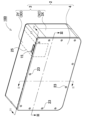
- FIG. 1 is a perspective view of a battery pack according to an embodiment of the present disclosure
- FIG. FIG. 2 is a partially enlarged cross-sectional view of the battery pack shown in FIG. 1 taken along line II-II.
- FIG. 3 is a partially enlarged cross-sectional view of the battery pack shown in FIG. 1 taken along line III-III.
- FIG. 4 is a cross-sectional view of the battery pack shown in FIG. 1 taken along line IV-IV.
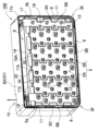
- 5 is an exploded perspective view of the battery pack shown in FIG. 1.
- FIG. 6 is a perspective view of the battery pack shown in FIG. 1 with a closing plate removed;
- FIG. 7 is a rear perspective view of the battery pack shown in FIG. 1 with a closing plate removed;
- a battery pack includes a battery block formed by connecting a plurality of battery cells having a discharge valve with a lead plate, and a battery block disposed on the outer periphery of the battery block, and ejected from the discharge valve to the outside. and a cover portion having a gas outlet for exhausting gas.
- each battery cell is arranged in a parallel posture, the electrode end faces of the battery cells are arranged in the same direction, and lead plates are connected to the electrode end faces arranged in the same direction. It has a permeable gap for ejected matter discharged from the discharge valve of the battery cell.
- the cover part closes an opening of an outer peripheral wall arranged around the battery block with a closing plate, and arranges a jet discharge duct between the closing plate and the battery block.
- the discharge duct is divided into a diffusion duct and an outer duct by a dividing rib, and the dividing rib divides the outer duct along the outer periphery of the diffusion duct, and communicates ejected substances from the diffusion duct to the outer duct.
- Ejected matter that has an opening and is discharged from the discharge valve of the battery cell passes through the permeation gap of the lead plate, the diffusion duct, and the outer peripheral duct, and is discharged to the outside from the gas discharge port of the cover portion.
- the above battery pack achieves a high level of safety by preventing harmful effects such as ignition due to the discharge of high-temperature ejected matter to the outside of the cover. This is because the above-described battery pack can attenuate the energy of ejected matter through the exhaust duct provided inside the cover portion and exhaust it to the outside.
- the exhaust duct efficiently attenuates the energy of ejected matter and exhausts it to the outside in both the diffusion duct and the peripheral duct.
- the diffusion duct is a gap that spreads in a plane and diffuses ejected matter discharged from the battery cell in a plane to attenuate the energy.
- the ejected matter that has passed through the narrow transmission gap of the lead plate flows into the diffusion duct, collides with the inner surface of the closing plate, diffuses to the surroundings, spreads over a wide planar area, and the energy is attenuated.
- the ejected material flowing into the diffusion duct dissipates heat energy to the large-area closing plate and lead plate, and the heat energy is attenuated.
- the jet whose energy has been attenuated by the diffusion duct flows into the outer peripheral duct, where its energy is further attenuated and is discharged from the gas outlet.
- the outer peripheral duct causes ejected matter to flow through an elongated hollow passage to radiate heat energy, and also attenuates kinetic energy due to the flow resistance passing through, and discharges the ejected matter from the gas outlet.
- the outer peripheral duct has one end serving as a first end, the other end serving as a second end, and the first end communicating with a gas discharge port.
- a communication opening can be arranged between the second end and the central portion of the peripheral duct.
- the outer peripheral duct forms a closed chamber between the communication opening and the second end, ejected matter passing through the communication opening collides with the inner surface of the outer peripheral wall, which is the outer wall of the outer peripheral duct. branched to both sides. A portion of the ejected product that is branched flows into the closed chamber and reduces the flow velocity on the discharge side. Therefore, the energy of the high-temperature ejected substance, which flows at high speed and is discharged at the moment the discharge valve is opened, is attenuated by the cushioning action of the sealed chamber.
- This structure suppresses leakage fire at the gas discharge port due to ejected matter discharged as a high-speed flow immediately after the discharge valve is opened.
- a battery block in a battery pack according to another embodiment of the present disclosure, includes a battery holder in which a plurality of battery cells are arranged at fixed positions, and a cover portion is an outer peripheral wall of the holder integrally formed with the battery holder. and a separate outer peripheral wall connected to the outer peripheral wall of the holder and having the battery blocks arranged therein.
- the cover part is integrally formed with the battery holder, so there is no need for a dedicated exterior case for housing the battery block, and the cover can be of a simple structure. Furthermore, since the cover part is formed by connecting the separated outer peripheral wall to the outer peripheral wall of the battery holder, which has an integral structure with the battery holder, it is possible to provide a storage space for arranging built-in parts such as a circuit board inside the separated outer peripheral wall. .
- a battery pack according to another embodiment of the present disclosure can integrally mold the dividing ribs with the battery holder.
- the partitioning ribs integrally formed with the battery holder partition the diffusion duct and the peripheral duct while preventing leakage of ejected matter, allowing the ejected matter to flow from the diffusion duct to the peripheral duct through the communication opening.
- the inflow and exhaust ducts can reliably attenuate the energy of the jet.
- the closing plate has a fitting recess that connects the partitioning ribs with a fitting structure, and the partitioning ribs can be guided to the fitting recess and connected to the closure plate. can.
- the dividing ribs and the closing plate are connected without gaps, so that the leakage of ejected matter from the diffusion duct and the outer peripheral duct can be prevented more effectively. Therefore, the ejected matter from the diffusion duct flows into the outer peripheral duct through the communication opening without fail, and the energy of the ejected matter in the discharge duct can be more reliably attenuated.
- a battery pack according to another embodiment of the present disclosure can integrally form a closing plate and partition ribs.
- This structure can connect the dividing ribs and the closing plate without any gap, so that the leakage of the ejected substance from the diffusion duct and the outer peripheral duct is prevented, and the ejected substance from the diffusion duct flows into the outer peripheral duct from the communication opening without leakage.
- the energy of ejected matter in the exhaust duct can be more reliably attenuated.
- the battery block includes a battery holder formed by arranging a plurality of battery cells at fixed positions, and the dividing ribs are separate members from the battery holder and the closing plate, and the battery It can be arranged between the holder and the closure plate.
- a battery pack according to another embodiment of the present disclosure has a cover portion that has a rectangular outer shape, includes first to fourth outer peripheral walls, and has outer peripheral ducts arranged along inner sides of the first to third outer peripheral walls. and the gas outlet can be opened in the fourth outer peripheral wall.
- energy is attenuated by ejected matter flowing through long outer peripheral ducts arranged along the first to third outer peripheral walls. Furthermore, the ejected matter collides with the inner surface of the outer peripheral wall at both the corner portions of the first and second outer peripheral walls and the corner portions of the second and third outer peripheral walls and changes direction, further attenuating the energy. , the ejected substance whose energy has been attenuated is discharged to the outside from the gas discharge port of the fourth outer peripheral wall, thereby more effectively suppressing the harmful effects of leakage fire.
- a battery block in a battery pack according to another embodiment of the present disclosure, includes a battery holder in which a plurality of battery cells are arranged at fixed positions, and a cover portion is an outer peripheral wall of the holder integrally formed with the battery holder. and a separation outer wall connected to the holder outer wall and having the battery block disposed inside, wherein the first to third outer walls are the holder outer wall, and the fourth outer wall is the separation outer wall. can do.
- a board storage space for storing a circuit board is provided between the separation outer wall and the battery block, and ejected matter is provided between the board storage space and the diffusion duct.
- the ends of the shielding ribs can be connected to the ends of the partitioning ribs.
- a battery pack according to another embodiment of the present disclosure can partition the substrate storage space and the diffusion duct by the shielding rib, and allow communication between the outer peripheral duct and the substrate storage space.
- ejected matter discharged from the outer peripheral duct flows into the substrate storage space from the outer peripheral duct, where it is diffused and energy is attenuated.
- the ejected matter whose energy has been attenuated can be more effectively prevented from being discharged from the gas outlet to the outside of the case and becoming a leakage fire.
- shielding ribs can be integrally molded with partitioning ribs.
- the fourth outer peripheral wall has a collision wall at the corner for ejected material that flows out from the end of the outer peripheral duct, and the gas discharge port is located at the center of the collision wall. can be opened.
- the permeation gap of the lead plate can be set to 1 mm or less, and the gap (d) between the closing plate and the lead plate of the diffusion duct can be set to 3 mm or more.
- the inner width (W) between the outer peripheral wall and the partitioning ribs of the outer peripheral duct can be 1 cm or less.
- a battery pack 100 shown in FIGS. 1 to 7 includes a battery block 10 in which a plurality of battery cells 1 having discharge valves are connected by lead plates 11, and a cover portion 2 arranged on the outer circumference of the battery block 10. .
- the cover portion 2 is provided with a gas exhaust port 15 for exhausting ejected matter discharged from the exhaust valve of the battery cell 1 to the outside of the case.
- the battery cells 1 are arranged in parallel, the electrode end faces 1A of the battery cells 1 are arranged in the same direction, and the lead plates 11 are connected to the electrode end faces 1A arranged in the same direction. Therefore, the battery cells 1 are connected in series or in parallel.
- the battery block 10 has a plurality of battery cells 1 arranged in a parallel posture, electrode end surfaces 1A of the plurality of battery cells 1 arranged on the same plane, and electrodes arranged on the same plane.
- the battery cells 1 are connected in series or in parallel by connecting the lead plates 11 to the end faces 1A. It may be shifted.
- the lead plate 11 of the battery block 10 is provided with a permeable gap 12 through which ejected substances discharged from the opened discharge valve pass.
- the cover part 2 closes the opening surface of the outer peripheral wall 3 in which the battery block 10 is arranged with the closing plate 4, and inside the closing plate 4, there is a diffusion
- a discharge duct 5 consisting of a duct 5A and a peripheral duct 5B is provided.
- the discharge duct 5 is partitioned into a diffusion duct 5A and an outer peripheral duct 5B by partitioning ribs 6 in order to efficiently attenuate the energy of ejected matter.
- the partition rib 6 partitions the outer peripheral duct 5B along the outer peripheral portion of the diffusion duct 5A. Furthermore, the partition rib 6 is provided with a communication opening 16 that allows jetted matter to flow from the diffusion duct 5A to the outer peripheral duct 5B.
- ejected matter discharged from the discharge valve of the battery cell 1 is passed through the permeation gap 12 of the lead plate 11 ⁇ the diffusion duct 5A ⁇ the communication opening 16 ⁇ the outer peripheral duct 5B, and is discharged through the gas discharge port of the cover part 2. 15 is discharged to the outside without causing leakage fire.
- the battery cell 1 is a cylindrical battery having electrode end faces 1A at both ends.
- the battery pack of the present disclosure does not specify batteries as cylindrical batteries.
- Battery cells of other shapes, such as rechargeable prismatic batteries, can also be used for the battery cells 1 .
- Cylindrical batteries contain electrodes and an electrolyte in a cylindrical metal case.
- the metal case has a sealed structure in which a sealing plate is airtightly fixed to the opening of the outer can that closes the bottom.
- the outer can is manufactured by pressing a metal plate.
- the sealing plate is air-tightly fixed to the periphery of the opening of the outer can by crimping through an insulating packing.
- a prismatic battery has insulated positive and negative electrode terminals provided on a sealing plate that closes an opening of a metal case.
- the battery cell 1 is provided with a discharge valve 1v on the sealing plate in order to prevent damage due to abnormally high internal pressure of the metal case.
- the discharge valve 1v has a sealing plate provided with an injection opening for discharging ejected matter containing gas or the like in an open state.
- the battery cell can also be provided with a discharge valve and its injection opening at the bottom of the outer can.
- the discharge valve 1v opens when the internal pressure exceeds a set pressure, for example, 1.5 MPa, to prevent the metal case from breaking due to the internal pressure increase.
- the discharge valve 1v opens in an abnormal state. Therefore, when the discharge valve 1v is open, the temperature of the battery cell 1 is also very high.
- the ejected material discharged from the open discharge valve 1v is at an abnormally high temperature due to the mixture of gas and electrolytic solution (ejected material).
- the battery cell 1 is a non-aqueous electrolyte secondary battery such as a lithium ion battery
- ejected matter may reach an abnormally high temperature of 400° C. or higher.
- the lithium-ion battery is filled with a non-aqueous electrolyte, if it is discharged outside the case at a high temperature, it may come into contact with air and ignite, resulting in an even higher temperature.
- the ejected material ejected from the open exhaust valve 1v becomes hot, so it is safe to attenuate the energy of the ejected material and exhaust it outside the case. is important because it raises
- the battery block 10 has a plurality of battery cells 1 arranged in fixed positions with a battery holder 7 made of plastic.
- 60 cylindrical batteries are housed in the battery holder 7 and arranged in 6 rows and 10 rows.
- each battery cell 1 is arranged in parallel, the electrode end faces 1A of the battery cells 1 are arranged in the same direction, and the lead plates 11 are connected to the electrode end faces 1A in the same direction.
- the lead plate 11 is provided with a permeation gap 12 through which ejected substances discharged from the discharge valve 1v pass.
- a battery block 10 in FIG. 5 connects a plurality of battery cells 1 in series and in parallel with a plurality of lead plates 11 .
- Adjacent lead plates 11 are arranged with an insulating gap, which serves as a permeable gap 12 for ejected matter discharged from the discharge valve 1v of the battery cell 1 .
- the lead plate 11 is formed by cutting a metal plate and providing the arm portion 11a which is welded to the electrode of the battery cell 1, the permeation gap 12 for ejected matter is also provided on the outer periphery of the arm portion 11a. Ejected matter discharged from the discharge valve 1v of the battery cell 1 passes through the permeation gap 12 of the lead plate 11 and flows out from the back surface of the lead plate 11 to the front surface.
- the ejected substance that has flowed out to the surface of the lead plate 11 is discharged to the outside of the cover portion 2 through the discharge duct 5, which will be described later.
- the battery holder 7 of FIG. 5 has an outer peripheral wall 3 as an outer peripheral portion, and the outer peripheral wall 3 of the cover portion 2 is integrally formed.
- the cover portion 2 and the battery holder 7 are not necessarily molded into an integral structure, but the battery holder 7 is arranged inside the outer peripheral wall 3 as a separate member, and the battery holder 7 is used to form the battery cell. 1 can also be arranged at a fixed position.
- the battery holder 7 shown in FIG. 5 is provided by molding an insulating plastic material and integrally molding the insertion cylindrical portions 21 for the plurality of battery cells 1 .
- the insertion cylinder part 21 holds the battery cell 1 set here in a fixed position.
- the illustrated battery holder 7 has a shape in which the battery cell 1 is a cylindrical battery, and the insertion tube portion 21 is configured to insert the cylindrical battery and hold it in a fixed position.
- the battery holder 7 shown in the figure arranges 60 battery cells 1 in 6 vertical tiers, and 10 rows of batteries are arranged in each tier. They are arranged so as to take the posture of stacking bales in which the cells 1 are arranged.
- the battery holder 7 is divided into a pair of cell holders 7A and 7B as shown in FIG.
- Each of the cell holders 7A and 7B constituting the battery holder 7 is provided with an insertion tube portion 21 into which the battery cells 1 are inserted in a parallel posture.
- the insertion cylinder part 21 is opened at both ends to expose the electrode end face 1A of the cylindrical battery inserted therein, and the lead plate 11 can be connected to the electrode end face 1A.
- the insertion cylindrical portions 21 of the cell holders 7A and 7B are long enough to insert approximately half of the battery cells 1.
- Each battery cell 1 is inserted half into one cell holder 7A and the other half into the other cell. It is inserted into the holder 7B and arranged at a fixed position of the battery holder 7.
- the battery holder 7 having the structure described above securely holds the plurality of battery cells 1 while arranging them in fixed positions. There are features that can be done.
- the battery holder 7 also has the lead plates 11 arranged in a fixed position with a fitting structure.
- the battery holder 7 is provided with a fitting recess for guiding the lead plate 11, the lead plate 11 is set in this fitting recess, and can be placed in a fixed position with the fitting structure.
- the fitting structure of the battery cell 1 and the lead plate 11 is such that a through hole is provided in the lead plate 11 and a positioning rib inserted through the through hole is formed integrally with the battery holder 7 and positioned.
- the lead plate 11 can be placed at a fixed position on the battery holder 7 by inserting the ribs into the through holes.
- the electrode end faces 1A at both ends of the battery cell 1 are arranged in the same direction, and the lead plates 11 are welded to the electrodes provided on the electrode end faces 1A.
- the lead plate 11 can be connected to the electrodes by laser welding, spot welding, ultrasonic welding, or the like.
- the cover part 2 is made of a thermoplastic resin such as polycarbonate having excellent heat resistance properties, and has a rectangular outer shape.
- the illustrated cover portion 2 is composed of an outer peripheral wall 3 having a rectangular outer shape and a closing plate 4 closing an opening of the outer peripheral wall 3 .
- the outer peripheral wall 3 is composed of a holder outer peripheral wall 3X integrally formed with the battery holder 7 and a separate outer peripheral wall 3Y connected to the holder outer peripheral wall 3X and having the circuit board 13 and the battery block 10 arranged inside.
- the outer peripheral wall 3 shown in FIGS. 1 to 5 has a rectangular outer shape, and the opening is closed with a rectangular closing plate 4 .
- the closing plate 4 is screwed into connecting bosses 24 provided inside the battery holder 7 and the separation outer peripheral wall 3Y via a plurality of setscrews 23 penetrating the outer peripheral edge to be fixed in place on the outer peripheral wall 3 .
- the discharge duct 5 attenuates the energy of the ejected substance and discharges it from the gas outlet 15 in order to prevent the ejected substance discharged to the outside of the cover portion 2 from leaking.
- the cover part 2 fixes the closing plate 4 to the opening of the outer peripheral wall 3 where the battery block 10 is arranged at a fixed position, and arranges the discharge duct 5 inside the closing plate 4 .
- the discharge duct 5 is divided into a diffusion duct 5A and an outer peripheral duct 5B, and the outer peripheral duct 5B is arranged along the outer periphery of the diffusion duct 5A.
- the diffusion duct 5A is a quadrangular space extending in a plane, and the outer peripheral duct 5B is an elongated hollow portion provided along the outer periphery of the diffusion duct 5A.
- the battery pack 100 has exhaust ducts 5 facing both sides of the battery block.
- the discharge duct 5 is provided with a partition rib 6 between the battery holder 7 and the closing plate 4, and the partition rib 6 partitions the diffusion duct 5A and the peripheral duct 5B.
- the partitioning ribs 6 are arranged along the outer circumference of the diffusion duct 5A, and the outer circumference duct 5B is arranged along the outer circumference of the diffusion duct 5A.
- the partition rib 6 is provided with a communication opening 16, through which the ejected matter from the diffusion duct 5A is guided to the outer peripheral duct 5B.
- the dividing ribs 6 in FIGS. 2, 3, 6 and 7 are molded integrally with the battery holder 7. As shown in FIG.
- the dividing ribs 6 integrally formed with the battery holder 7 are provided with fitting recesses 20 for connecting the dividing ribs 6 with a fitting structure on the inner surface of the closing plate 4.
- a portion of the partitioning rib 6 is guided to the fitting recess 20 and arranged at a fixed position of the closing plate 4 .
- the partitioning ribs 6 can be arranged on both the battery holder 7 and the closing plate 4 so as not to create gaps through which ejected substances can leak, and can also be arranged at accurate positions without misalignment so that the discharge duct 5 can be separated from the diffusion duct 5A and the outer circumference of the diffusion duct 5A. It can be divided into ducts 5B.
- the partitioning ribs 6 are formed integrally with the closing plate 4, and the partitioning ribs 6 and the closing plate 4 are connected without gaps to prevent leakage of ejected substances. It can be placed in a fixed position without misalignment. Furthermore, the dividing ribs 6 are made of separate members from the battery holder 7 and the closing plate 4, and are fixed in place between the battery holder 7 and the closing plate 4 by fitting, joining, or welding. can also be placed.
- the diffusion duct 5A in the area surrounded by the partitioning ribs 6 is a gap that spreads in a plane, and diffuses in a plane the jet that flows in from the transmission gap 12 of the lead plate 11 to attenuate the energy.
- the ejected matter that has passed through the narrow transmission gap 12 of the lead plate 11 flows into the diffusion duct 5A, collides with the inner surface of the closing plate 4, diffuses and spreads over a wide planar area, and the energy is attenuated. Since the diffusion duct 5A is arranged between the closing plate 4 and the lead plate 11, the ejected substances flowing into the diffusion duct 5A dissipate heat energy to the wide area of the closing plate 4 and the lead plate 11, and the heat energy is attenuated. do.
- the temperature can also be lowered by adiabatically expanding the ejected matter that has passed through the narrow permeation gap 12 in the diffusion duct 5A. Temperature reduction due to adiabatic expansion is more effective when ejected matter that has passed through narrow permeation gap 12 is discharged into wide diffusion duct 5A. Therefore, the permeation gap 12 is narrowed, for example, the permeation gap 12 is set to 1 mm or less, and the gap (d) of the diffusion duct 5A is set to, for example, three times or more of the permeation gap 12, thereby effectively lowering the temperature of the ejected matter. It can be guided to the gas outlet 15 .
- the elongated outer peripheral duct 5B arranged on the outer periphery of the diffusion duct 5A causes the ejected substance to flow through the elongated hollow passage to radiate heat energy, and furthermore, the kinetic energy is attenuated by the flow resistance passing through, and the gas outlet 15 Eject from Since the outer peripheral duct 5B can attenuate the energy of ejected matter with flow resistance, it is preferable to set the inner width (W) between the outer peripheral wall 3 and the partitioning ribs 6 to 1 cm or less to efficiently attenuate the energy of the ejected matter.
- the cover part 2 of FIG. 4 is divided into the outer peripheral wall 3 from the first outer peripheral wall 3A to the fourth outer peripheral wall 3D, that is, the first outer peripheral wall 3A, the second outer peripheral wall 3B, the third outer peripheral wall 3C and the fourth outer peripheral wall 3C.
- As a square tube shape composed of an outer peripheral wall 3D it is divided inside the first outer peripheral wall 3A to the third outer peripheral wall 3C, that is, the first outer peripheral wall 3A, the second outer peripheral wall 3B, and the third outer peripheral wall 3C.
- a rib 6 is provided, and an outer peripheral duct 5B is provided along three sides of the quadrangle between the partitioning rib 6 and the outer peripheral wall 3.
- the fourth outer peripheral wall 3D opens a gas discharge port 15, and discharges ejected substances flowing from the outer peripheral duct 5B to the outside through the fourth outer peripheral wall 3D.
- the outer peripheral duct 5B arranged along the first outer peripheral wall 3A to the third outer peripheral wall 3C has one end serving as the first end 5a and communicates with the gas discharge port 15, and the other end as the first end 5a.
- the second end portion 5 b is blocked by a blocking rib 17 without communicating with the gas discharge port 15 .
- the outer peripheral duct 5B has a communication opening 16 arranged between the second end 5b and the central portion of the outer peripheral duct 5B.
- the discharge duct 5 shown in FIG. 4 is a region facing the first outer peripheral wall 3A, and has a communication opening 16 near the closing rib 17. As shown in FIG.
- the structure in which the communication opening 16 is provided at this position has the advantage that the distance from the communication opening 16 to the first end portion 5a can be increased.
- An elongated hollow outer peripheral duct 5B arranged along the first outer peripheral wall 3A to the third outer peripheral wall 3C dissipates heat and attenuates energy with flow resistance, and furthermore, the first outer peripheral wall 3A and the second outer peripheral wall 3A
- the ejected substance collides with the inner surface of the outer peripheral wall 3 at both the corner portion 3E of the outer peripheral wall 3B and the corner portion 3F of the second outer peripheral wall 3B and the third outer peripheral wall 3C, so that the energy can be further attenuated.
- the gas is discharged to the outside from the gas discharge port 15 .
- the cover part 2 of FIG. 4 is provided with shielding ribs 18 inside the fourth outer peripheral wall 3D in order to guide ejected matter to the gas outlet 15 of the fourth outer peripheral wall 3D through the exhaust duct 5. .
- the shielding rib 18 guides ejected matter from the diffusion duct 5A to the outer peripheral duct 5B and shields it from directly flowing into the gas discharge port 15 .
- Both ends of the shielding rib 18 are connected to both ends of the partitioning rib 6 and arranged between the closing plate 4 and the battery block 10 .
- the shielding rib 18 in FIGS. 2 and 4 has a laminated structure of a first shielding rib 18A integrally formed with the battery holder 7 and a second shielding rib 18B integrally formed with the closing plate 4. .
- a first shielding rib 18 ⁇ /b>A integrally formed with the battery holder 7 is integrally formed with the partitioning rib 6 .
- the first shielding rib 18A shown in FIGS. 6 and 7 has a wiring opening 22 for guiding the connecting piece 11b drawn out from the lead plate 11.
- the second shielding rib 18B integrally formed with the closing plate 4 is arranged in a laminated structure on the lead plate 11 side of the first shielding rib 18A.
- a connection piece 11b drawn out from the lead plate 11 is connected to an output terminal or connected to the circuit board 13 as a detection line for detecting an intermediate potential.
- the shielding rib 18 provides a board storage space 8 between the fourth outer peripheral wall 3D and the battery block 10, and the circuit board 13 is arranged in the board storage space 8.
- the shielding rib 18 is arranged between the substrate storage space 8 and the diffusion duct 5A to block the flow of the ejected matter of the diffusion duct 5A into the substrate storage space 8.
- the circuit board 13 is connected to the battery cell 1 and mounts a battery protection circuit and the like.
- the above-described cover portion 2 partitions the substrate storage space 8 from the diffusion duct 5A with the shielding ribs 18 to prevent the ejection of the diffusion duct 5A from directly flowing into the substrate storage space 8, and the gas discharge port 15 is closed.
- This structure can further attenuate the energy of ejected matter flowing in from the outer peripheral duct 5B in the substrate storage space 8 and discharge it to the outside from the gas discharge port 15 .
- the ejected matter flowing into the substrate storage space 8 thermally damages the circuit board 13, but the battery pack 100 from which the ejected matter has been discharged from the discharge valve 1v cannot be reused thereafter. Therefore, the battery pack 100, which can lower the temperature of the ejected substance discharged from the gas outlet 15 due to the thermal damage of the circuit board 13, can more effectively prevent leakage fires and ensure higher safety.
- the cover part 2 of FIGS. 4 and 6 does not open the gas discharge port 15 at the corner of the fourth outer peripheral wall 3D, and the outer peripheral wall 3D is provided with gas flowing out from the terminal end of the outer peripheral duct 5B.
- the gas discharge port 15 is opened in the central portion of the collision wall 19 .
- This battery pack 100 collides with the collision wall 19 to change the direction of ejected matter flowing into the substrate storage space 8 from the outer peripheral duct 5B, diffuses it into the substrate storage space 8, attenuates the energy more efficiently, and discharges the gas. 15 can be discharged.
- the label 25 closes the gas discharge port 15 opened in the fourth outer peripheral surface 4D.
- This label 25 uses a sheet material that is peeled off or melted by the exhaust gas discharged from the gas discharge port 15 .
- the label 25 closes the gas discharge port 15 of the cover portion 2 of the cover portion 2, thereby preventing foreign matter from entering the interior through the gas discharge port 15 of the cover portion 2. can be prevented.
- the label 25 is peeled off by the pressure of the exhaust gas passing through the exhaust duct 5, or melted and removed by the heat of the high-temperature exhaust gas. be.
- the circuit board 13 is connected to the board holder 14 with a fitting structure and placed in a fixed position. 2 and 5, the substrate holder 14 is arranged on the upper surface of the battery holder 7, and the circuit substrate 13 is arranged in the substrate storage space 8. As shown in FIG.
- the circuit board 13 mounts an electronic component that is connected to the battery cell 1 and implements a protection circuit for the battery cell 1 .
- the protection circuit is a circuit that prevents overcharging or overdischarging of the battery cell 1, a circuit that prevents overcurrent, or a circuit that cuts off the current when the temperature rises abnormally.
- the present disclosure can be effectively used for battery packs that safely exhaust spouts from battery cells to the outside.
- Battery pack 1 Battery cell 1A Electrode end surface 1v Discharge valve 2 Cover part 3 Outer peripheral wall 3A First outer peripheral wall 3B Second outer peripheral wall 3C Third outer peripheral wall 3D Fourth outer peripheral wall 3E Corner part 3F Corner part 3X Holder Outer peripheral wall 3Y Separate outer peripheral wall 4 Closure plate 5 Discharge duct 5A Diffusion duct 5B Outer duct 5a First end 5b Second end 6 Division rib 7 Battery holder 8 Substrate storage space 10 Battery block 11 Lead plate 11a Arm 11b Connection piece 12 Transmission gap 13 Circuit board 14 Board holder 15 Gas discharge port 16 Communication opening 17 Closing rib 18 Shielding rib 18A First shielding rib 18B Second shielding rib 19 Collision wall 20 Fitting recess 21 Insertion cylinder 22 Wiring opening 23 set screw 24 connecting boss 25 label
Landscapes
- Chemical & Material Sciences (AREA)
- Chemical Kinetics & Catalysis (AREA)
- Electrochemistry (AREA)
- General Chemical & Material Sciences (AREA)
- Battery Mounting, Suspending (AREA)
- Gas Exhaust Devices For Batteries (AREA)
Abstract
Description
図1~図7に示す電池パック100は、排出弁を備える複数の電池セル1をリード板11で接続している電池ブロック10と、電池ブロック10の外周に配置されるカバー部2とを備える。カバー部2は、電池セル1の排出弁から排出される噴出物をケースの外部に排気するガス排出口15を設けている。電池ブロック10は、電池セル1を平行姿勢に配置して、電池セル1の電極端面1Aの向きを同一方向に配置して、同一方向に配置している電極端面1Aにリード板11を接続して、電池セル1を直列や並列に接続している。本実施の形態においては、電池ブロック10は、複数の電池セル1を平行姿勢に配置して、複数の電池セル1の電極端面1Aを同一平面に配置して、同一平面に配置している電極端面1Aにリード板11を接続して、電池セル1を直列や並列に接続しているが、複数の電池セル1の電極端面1Aを必ずしも同一平面に配置していなくいてもよく、互いに位置がずれていてもよい。電池ブロック10のリード板11は、開弁した排出弁から排出される噴出物が透過する透過隙間12を設けている。カバー部2は、電池ブロック10を内側に配置する外周壁3の開口面を閉塞プレート4で閉塞して、閉塞プレート4の内側には、噴出物のエネルギーを減衰して外部に排出する、拡散ダクト5Aと外周ダクト5Bからなる排出ダクト5を設けている。排出ダクト5は、噴出物のエネルギーを効率よく減衰するために、区画リブ6で拡散ダクト5Aと外周ダクト5Bとに区画している。区画リブ6は、拡散ダクト5Aの外周部に沿って外周ダクト5Bを区画している。さらに、区画リブ6は拡散ダクト5Aから外周ダクト5Bに噴出物を流入させる連通開口16を設けている。この電池パック100は、電池セル1の排出弁から排出される噴出物を、リード板11の透過隙間12→拡散ダクト5A→連通開口16→外周ダクト5Bに通過させてカバー部2のガス排出口15から漏れ火を発生させることなく外部に排出する。
電池セル1は両端を電極端面1Aとする円筒形電池である。ただ、本開示の電池パックは電池を円筒形電池には特定しない。電池セル1には充電できる角形電池等の他の形状の電池も使用できる。円筒形電池は、円筒状の金属ケースに電極と電解液を収納している。金属ケースは、底を閉塞している外装缶の開口部に、封口板を気密に固定している密閉構造としている。外装缶は、金属板をプレス加工して製作される。封口板は、絶縁材のパッキンを介して外装缶の開口部周縁にカシメ加工して気密に固定される。角形電池は、金属ケースの開口部を閉塞する封口板に、絶縁して正負の電極端子を設けている。
電池ブロック10は、プラスチック製の電池ホルダー7で複数の電池セル1を定位置に配置している。図5の電池ブロック10は、60本の円筒形電池を電池ホルダー7に収納して、6段10列に配列している。図5の電池ブロック10は、各々の電池セル1を平行姿勢として、電池セル1の電極端面1Aの向きを同一方向に配置して、同一方向の電極端面1Aにリード板11を接続している。リード板11は、排出弁1vから排出される噴出物を通過させる透過隙間12を設けている。
図5の電池ホルダー7は、外周部を外周壁3として、カバー部2の外周壁3を一体構造に成形している。ただ、本開示の電池パックは、カバー部2と電池ホルダー7とを必ずしも一体構造に成形することなく、別部材として外周壁3の内側に電池ホルダー7を配置して、電池ホルダー7で電池セル1を定位置に配置する構造とすることもできる。図5の電池ホルダー7は、絶縁材のプラスチックを成形して、複数の電池セル1の挿入筒部21を一体的に成形して設けている。挿入筒部21は、ここにセットされる電池セル1を定位置に保持する。図の電池ホルダー7は、電池セル1を円筒形電池として、挿入筒部21を、円筒形電池を挿入して定位置に保持する形状としている。図の電池ホルダー7は、60本の電池セル1を、上下6段に配列すると共に、各段に配置される電池を10列として、左右に隣接する電池セル1の谷間に上下に位置する電池セル1を配置する俵積みの姿勢となるように配列している。
カバー部2は、ポリカーボネート等の耐熱特性に優れた熱可塑性の樹脂製で、外形を四角形に成形して、内側には電池ブロック10と回路基板13を配置している。図のカバー部2は、外形を四角形とする外周壁3と、この外周壁3の開口部を閉塞している閉塞プレート4とからなる。外周壁3は、電池ホルダー7と一体構造に成形されたホルダー外周壁3Xと、ホルダー外周壁3Xに連結されて、回路基板13と電池ブロック10を内側に配置している分離外周壁3Yとからなる。図1から図5の外周壁3は、外形を四角形として、開口部を四角形の閉塞プレート4で閉塞している。閉塞プレート4は、外周縁部を貫通する複数の止ネジ23を介して電池ホルダー7と分離外周壁3Yの内側に設けた連結ボス24にねじ込まれて外周壁3の定位置に固定される。
排出ダクト5は、電池ホルダー7と閉塞プレート4との間に区画リブ6を設けて、この区画リブ6で拡散ダクト5Aと外周ダクト5Bを区画している。区画リブ6は、拡散ダクト5Aの外周部に沿って配置されて、拡散ダクト5Aの外周に沿って外周ダクト5Bを配置している。さらに区画リブ6は連通開口16を設けて、この連通開口16で拡散ダクト5Aの噴出物を外周ダクト5Bに案内している。図2、図3、図6及び図7の区画リブ6は、電池ホルダー7と一体的に成形されている。さらに、図2及び図3の一部拡大断面図に示す電池ホルダー7と一体構造の区画リブ6は、閉塞プレート4の内面に、区画リブ6を嵌合構造で連結する嵌合凹部20を設けて、この嵌合凹部20に区画リブ6の一部を案内して、閉塞プレート4の定位置に配置している。この区画リブ6は、電池ホルダー7と閉塞プレート4の両方に、噴出物が漏れる隙間ができないように配置でき、さらに位置ずれなく正確な位置に配置して、排出ダクト5を拡散ダクト5Aと外周ダクト5Bに区画できる。
さらに、図1に示すカバー部2は、第4の外周面4Dに開口されたガス排出口15をラベル25で閉塞している。このラベル25は、ガス排出口15から排出される排出ガスで剥離され、あるいは溶融されるシート材を使用する。この電池パック100は、カバー部2のカバー部2に開口されたガス排出口15をラベル25で閉塞することで、カバー部2のガス排出口15を通過して内部に異物が侵入するのを防止できる。このラベル25は、電池セル1の排出弁1vから排出ガスが排出される際には、排出ダクト5を通過する排出ガスの圧力により剥離し、あるいは高温の排出ガスの熱により溶融されて除去される。
回路基板13は、基板ホルダー14に嵌合構造で連結されて定位置に配置される。基板ホルダー14、図2及び図5において、電池ホルダー7の上面に配置されており、基板収納スペース8に回路基板13を配置している。回路基板13は、電池セル1に接続されて電池セル1の保護回路を実現する電子部品を実装している。保護回路は、電池セル1の過充電や過放電を防止する回路、あるいは過電流を防止する回路、あるいは又温度が異常に上昇する状態で電流を遮断する回路である。
1 電池セル
1A 電極端面
1v 排出弁
2 カバー部
3 外周壁
3A 第1の外周壁
3B 第2の外周壁
3C 第3の外周壁
3D 第4の外周壁
3E コーナー部
3F コーナー部
3X ホルダー外周壁
3Y 分離外周壁
4 閉塞プレート
5 排出ダクト
5A 拡散ダクト
5B 外周ダクト
5a 第1の端部
5b 第2の端部
6 区画リブ
7 電池ホルダー
8 基板収納スペース
10 電池ブロック
11 リード板
11a アーム部
11b 接続片
12 透過隙間
13 回路基板
14 基板ホルダー
15 ガス排出口
16 連通開口
17 閉塞リブ
18 遮蔽リブ
18A 第1の遮蔽リブ
18B 第2の遮蔽リブ
19 衝突壁
20 嵌合凹部
21 挿入筒部
22 配線開口
23 止ネジ
24 連結ボス
25 ラベル
Claims (15)
- 排出弁をそれぞれ備える複数の電池セルをリード板で接続してなる電池ブロックと、
前記電池ブロックの外周に配置され、かつ前記排出弁からの噴出物を外部に排気するガス排出口を有するカバー部と、を備え、
前記電池ブロックでは、前記複数の電池セルが互いに平行であり、前記複数の電池セルの電極端面の向きを同一方向に配置して、前記電極端面に前記リード板が接続されており、
前記リード板は、前記噴出物が透過する透過隙間を有し、
前記カバー部は、前記電池ブロックの周囲に配置された外周壁と、前記外周壁の開口面を閉塞する閉塞プレートと、前記閉塞プレートと前記電池ブロックとの間に配置されて前記噴出物を排出する排出ダクトとを備え、
前記排出ダクトは、区画リブでもって拡散ダクトと外周ダクトに区画されており、
前記区画リブは、前記拡散ダクトの外周部に沿って前記外周ダクトを区画して、前記拡散ダクトから前記外周ダクトに前記噴出物を流入させる連通開口を有し、
前記複数の電池セルの前記排出弁から排出される前記噴出物が、前記リード板の前記透過隙間と前記拡散ダクトと前記外周ダクトを通過して、前記カバー部の前記ガス排出口から外部に排出される電池パック。 - 請求項1に記載する電池パックであって、
前記外周ダクトは第1の端部と第2の端部とを有し、
前記外周ダクトの前記第1の端部が前記ガス排出口に連通されて、
前記外周ダクトの前記第2の端部と前記外周ダクトの中央部との間に、前記連通開口が配置されている電池パック。 - 請求項1または2に記載する電池パックであって、
前記電池ブロックが、前記複数の電池セルを定位置に配置する電池ホルダーをさらに備え、
前記カバー部は、
前記電池ホルダーと一体構造に成形されたホルダー外周壁と、
前記ホルダー外周壁に連結されて、前記電池ブロックを内側に配置している分離外周壁とをさらに備える電池パック。 - 請求項3に記載する電池パックであって、
前記区画リブが前記電池ホルダーと一体的に成形されている電池パック。 - 請求項4に記載する電池パックであって、
前記閉塞プレートは、前記区画リブを嵌合構造で連結する嵌合凹部を有し、
前記区画リブが前記嵌合凹部に案内されて前記閉塞プレートに連結されている電池パック。 - 請求項1から3のいずれか一項に記載する電池パックであって、
前記閉塞プレートが、前記区画リブを一体的に成形してなる電池パック。 - 請求項1から3のいずれか一項に記載する電池パックであって、
前記電池ブロックが、前記複数の電池セルを定位置に配置してなる電池ホルダーをさらに備え、
前記区画リブが、前記電池ホルダーと前記閉塞プレートと別部材であって、前記電池ホルダーと前記閉塞プレートとの間に配置されている電池パック。 - 請求項1から7のいずれか一項に記載の電池パックであって、
前記カバー部の外形が四角形で第1の外周壁と第2の外周壁と第3の外周壁と第4の外周壁を備え、
前記外周ダクトが、前記第1の外周壁と前記第2の外周壁と前記第3の外周壁の内側に沿って配置されて、
前記ガス排出口が前記第4の外周壁に開口している電池パック。 - 請求項8に記載の電池パックであって、
前記電池ブロックが、前記複数の電池セルを定位置に配置している電池ホルダーをさらに備え、
前記カバー部が、
前記電池ホルダーと一体構造に成形されたホルダー外周壁と、
前記ホルダー外周壁に連結されて、前記電池ブロックを内側に配置している分離外周壁とをさらに備え、
前記第1の外周壁と前記第2の外周壁と前記第3の外周壁が前記ホルダー外周壁であり、前記第4の外周壁が前記分離外周壁である電池パック。 - 請求項9に記載の電池パックであって、
前記分離外周壁と前記電池ブロックとの間に、回路基板を収納する基板収納スペースが設けられており、
前記基板収納スペースと前記拡散ダクトとの間に配置されて、噴出物を遮蔽する遮蔽リブを備え、
前記遮蔽リブの両端が前記区画リブの両端に連結されている電池パック。 - 請求項10に記載の電池パックであって、
前記遮蔽リブが前記基板収納スペースと前記拡散ダクトとを区画して、前記外周ダクトと前記基板収納スペースとを連通させている電池パック。 - 請求項10または11に記載の電池パックであって、
前記遮蔽リブが前記区画リブと一体的に成形されている電池パック。 - 請求項8から12のいずれか一に記載の電池パックであって、
前記噴出物は前記外周ダクトの終端から流出し、
前記第4の外周壁は、前記に設けられた衝突壁を有し、
前記外周ダクトの前記終端から流出される噴出物は前記衝突壁に衝突し、
前記ガス排出口が、前記第4の外周壁のうちの前記衝突壁よりも中央部の近くに開口されている電池パック。 - 請求項1から13のいずれか一に記載の電池パックであって、
前記リード板の透過隙間が1mm以下で、
前記拡散ダクトの、前記閉塞プレートと前記リード板との間の隙間が3mm以上である電池パック。 - 請求項1から14のいずれか一に記載の電池パックであって、
前記外周ダクトの、前記外周壁と前記区画リブとの内幅(W)が1cm以下であることを特徴とする電池パック。
Priority Applications (4)
| Application Number | Priority Date | Filing Date | Title |
|---|---|---|---|
| EP23763110.6A EP4489205A4 (en) | 2022-03-04 | 2023-01-05 | BATTERY PACK |
| US18/840,922 US20250167385A1 (en) | 2022-03-04 | 2023-01-05 | Battery pack |
| JP2024504381A JPWO2023166847A1 (ja) | 2022-03-04 | 2023-01-05 | |
| CN202380024211.6A CN118786568A (zh) | 2022-03-04 | 2023-01-05 | 电池组 |
Applications Claiming Priority (2)
| Application Number | Priority Date | Filing Date | Title |
|---|---|---|---|
| JP2022-033540 | 2022-03-04 | ||
| JP2022033540 | 2022-03-04 |
Publications (1)
| Publication Number | Publication Date |
|---|---|
| WO2023166847A1 true WO2023166847A1 (ja) | 2023-09-07 |
Family
ID=87883603
Family Applications (1)
| Application Number | Title | Priority Date | Filing Date |
|---|---|---|---|
| PCT/JP2023/000039 Ceased WO2023166847A1 (ja) | 2022-03-04 | 2023-01-05 | 電池パック |
Country Status (5)
| Country | Link |
|---|---|
| US (1) | US20250167385A1 (ja) |
| EP (1) | EP4489205A4 (ja) |
| JP (1) | JPWO2023166847A1 (ja) |
| CN (1) | CN118786568A (ja) |
| WO (1) | WO2023166847A1 (ja) |
Citations (6)
| Publication number | Priority date | Publication date | Assignee | Title |
|---|---|---|---|---|
| JP2008117765A (ja) | 2006-10-13 | 2008-05-22 | Matsushita Electric Ind Co Ltd | 電池パック及び電池搭載機器並びに電池パックの接続構造 |
| WO2020153018A1 (ja) * | 2019-01-25 | 2020-07-30 | 三洋電機株式会社 | パック電池 |
| JP2020123540A (ja) * | 2019-01-31 | 2020-08-13 | パナソニックIpマネジメント株式会社 | 蓄電池モジュール |
| WO2021019970A1 (ja) * | 2019-07-29 | 2021-02-04 | 三洋電機株式会社 | 電池パック |
| JP2021022545A (ja) * | 2019-07-30 | 2021-02-18 | 三洋電機株式会社 | 電源装置 |
| WO2022009564A1 (ja) * | 2020-07-09 | 2022-01-13 | 株式会社Gsユアサ | 蓄電装置 |
Family Cites Families (2)
| Publication number | Priority date | Publication date | Assignee | Title |
|---|---|---|---|---|
| JP5466906B2 (ja) * | 2009-09-18 | 2014-04-09 | パナソニック株式会社 | 電池モジュール |
| JP6883774B2 (ja) * | 2016-12-27 | 2021-06-09 | パナソニックIpマネジメント株式会社 | 電池モジュール |
-
2023
- 2023-01-05 CN CN202380024211.6A patent/CN118786568A/zh active Pending
- 2023-01-05 JP JP2024504381A patent/JPWO2023166847A1/ja active Pending
- 2023-01-05 WO PCT/JP2023/000039 patent/WO2023166847A1/ja not_active Ceased
- 2023-01-05 EP EP23763110.6A patent/EP4489205A4/en active Pending
- 2023-01-05 US US18/840,922 patent/US20250167385A1/en active Pending
Patent Citations (6)
| Publication number | Priority date | Publication date | Assignee | Title |
|---|---|---|---|---|
| JP2008117765A (ja) | 2006-10-13 | 2008-05-22 | Matsushita Electric Ind Co Ltd | 電池パック及び電池搭載機器並びに電池パックの接続構造 |
| WO2020153018A1 (ja) * | 2019-01-25 | 2020-07-30 | 三洋電機株式会社 | パック電池 |
| JP2020123540A (ja) * | 2019-01-31 | 2020-08-13 | パナソニックIpマネジメント株式会社 | 蓄電池モジュール |
| WO2021019970A1 (ja) * | 2019-07-29 | 2021-02-04 | 三洋電機株式会社 | 電池パック |
| JP2021022545A (ja) * | 2019-07-30 | 2021-02-18 | 三洋電機株式会社 | 電源装置 |
| WO2022009564A1 (ja) * | 2020-07-09 | 2022-01-13 | 株式会社Gsユアサ | 蓄電装置 |
Non-Patent Citations (1)
| Title |
|---|
| See also references of EP4489205A4 |
Also Published As
| Publication number | Publication date |
|---|---|
| CN118786568A (zh) | 2024-10-15 |
| EP4489205A4 (en) | 2025-08-13 |
| JPWO2023166847A1 (ja) | 2023-09-07 |
| EP4489205A1 (en) | 2025-01-08 |
| US20250167385A1 (en) | 2025-05-22 |
Similar Documents
| Publication | Publication Date | Title |
|---|---|---|
| US12074338B2 (en) | Battery pack | |
| US12294107B2 (en) | Battery pack | |
| KR102919208B1 (ko) | 냉각수를 활용한 배터리 셀의 열확산 방지 구조를 갖춘 배터리 모듈 및 이를 포함하는 배터리 팩 | |
| KR102690299B1 (ko) | 방열부재를 포함하는 전지모듈 및 상기 방열부재의 제조방법 | |
| ES2975961T3 (es) | Cuerpo de caja de batería, batería, dispositivo eléctrico y método para preparar el cuerpo de caja | |
| WO2021088570A1 (zh) | 电池包及装置 | |
| KR102922132B1 (ko) | 전지팩 및 이를 포함하는 디바이스 | |
| JP7758418B2 (ja) | 熱拡散抑制構造を含む電池パック | |
| WO2020152992A1 (ja) | パック電池 | |
| KR20210112163A (ko) | 배터리 랙 및 이러한 배터리 랙을 포함하는 전력 저장 장치 | |
| KR102798544B1 (ko) | 전지 모듈 및 이를 포함하는 전지 팩 | |
| US20240072374A1 (en) | Battery module and battery pack comprising same | |
| KR102931493B1 (ko) | 전지 모듈 및 이를 포함하는 전지 팩 | |
| JP2012199186A (ja) | 電池モジュール | |
| KR102919503B1 (ko) | 열확산 억제 구조를 포함하는 전지팩 | |
| KR20230165712A (ko) | 전지 팩 및 이를 포함하는 디바이스 | |
| JP7609777B2 (ja) | パック電池 | |
| KR102919509B1 (ko) | 열확산 억제 구조를 포함하는 전지팩 | |
| WO2023166847A1 (ja) | 電池パック | |
| JP7576537B2 (ja) | 電源装置 | |
| US20240204326A1 (en) | Battery module, battery pack, and electronic device | |
| US20240380062A1 (en) | Battery pack, and ess and vehicle including the battery pack | |
| JP7842309B2 (ja) | バッテリーアセンブリ、これを含むバッテリーパックおよび自動車 | |
| KR20260057389A (ko) | 배터리 어셈블리, 이를 포함하는 배터리 팩 및 자동차 | |
| JP2026502191A (ja) | バッテリアセンブリおよびこれを含むバッテリパック |
Legal Events
| Date | Code | Title | Description |
|---|---|---|---|
| 121 | Ep: the epo has been informed by wipo that ep was designated in this application |
Ref document number: 23763110 Country of ref document: EP Kind code of ref document: A1 |
|
| ENP | Entry into the national phase |
Ref document number: 2024504381 Country of ref document: JP Kind code of ref document: A |
|
| WWE | Wipo information: entry into national phase |
Ref document number: 18840922 Country of ref document: US |
|
| WWE | Wipo information: entry into national phase |
Ref document number: 202380024211.6 Country of ref document: CN |
|
| WWE | Wipo information: entry into national phase |
Ref document number: 2023763110 Country of ref document: EP |
|
| NENP | Non-entry into the national phase |
Ref country code: DE |
|
| ENP | Entry into the national phase |
Ref document number: 2023763110 Country of ref document: EP Effective date: 20241004 |
|
| WWP | Wipo information: published in national office |
Ref document number: 18840922 Country of ref document: US |