WO2023167260A1 - 酸性ガスの回収システム及び回収方法 - Google Patents
酸性ガスの回収システム及び回収方法 Download PDFInfo
- Publication number
- WO2023167260A1 WO2023167260A1 PCT/JP2023/007689 JP2023007689W WO2023167260A1 WO 2023167260 A1 WO2023167260 A1 WO 2023167260A1 JP 2023007689 W JP2023007689 W JP 2023007689W WO 2023167260 A1 WO2023167260 A1 WO 2023167260A1
- Authority
- WO
- WIPO (PCT)
- Prior art keywords
- gas
- regeneration
- adsorbent
- desorbed
- recovery system
- Prior art date
- Legal status (The legal status is an assumption and is not a legal conclusion. Google has not performed a legal analysis and makes no representation as to the accuracy of the status listed.)
- Ceased
Links
Images


Classifications
-
- B—PERFORMING OPERATIONS; TRANSPORTING
- B01—PHYSICAL OR CHEMICAL PROCESSES OR APPARATUS IN GENERAL
- B01D—SEPARATION
- B01D53/00—Separation of gases or vapours; Recovering vapours of volatile solvents from gases; Chemical or biological purification of waste gases, e.g. engine exhaust gases, smoke, fumes, flue gases, aerosols
- B01D53/02—Separation of gases or vapours; Recovering vapours of volatile solvents from gases; Chemical or biological purification of waste gases, e.g. engine exhaust gases, smoke, fumes, flue gases, aerosols by adsorption, e.g. preparative gas chromatography
- B01D53/06—Separation of gases or vapours; Recovering vapours of volatile solvents from gases; Chemical or biological purification of waste gases, e.g. engine exhaust gases, smoke, fumes, flue gases, aerosols by adsorption, e.g. preparative gas chromatography with moving adsorbents, e.g. rotating beds
-
- B—PERFORMING OPERATIONS; TRANSPORTING
- B01—PHYSICAL OR CHEMICAL PROCESSES OR APPARATUS IN GENERAL
- B01D—SEPARATION
- B01D53/00—Separation of gases or vapours; Recovering vapours of volatile solvents from gases; Chemical or biological purification of waste gases, e.g. engine exhaust gases, smoke, fumes, flue gases, aerosols
- B01D53/22—Separation of gases or vapours; Recovering vapours of volatile solvents from gases; Chemical or biological purification of waste gases, e.g. engine exhaust gases, smoke, fumes, flue gases, aerosols by diffusion
- B01D53/229—Integrated processes (Diffusion and at least one other process, e.g. adsorption, absorption)
-
- B—PERFORMING OPERATIONS; TRANSPORTING
- B01—PHYSICAL OR CHEMICAL PROCESSES OR APPARATUS IN GENERAL
- B01D—SEPARATION
- B01D53/00—Separation of gases or vapours; Recovering vapours of volatile solvents from gases; Chemical or biological purification of waste gases, e.g. engine exhaust gases, smoke, fumes, flue gases, aerosols
- B01D53/02—Separation of gases or vapours; Recovering vapours of volatile solvents from gases; Chemical or biological purification of waste gases, e.g. engine exhaust gases, smoke, fumes, flue gases, aerosols by adsorption, e.g. preparative gas chromatography
- B01D53/04—Separation of gases or vapours; Recovering vapours of volatile solvents from gases; Chemical or biological purification of waste gases, e.g. engine exhaust gases, smoke, fumes, flue gases, aerosols by adsorption, e.g. preparative gas chromatography with stationary adsorbents
- B01D53/0462—Temperature swing adsorption
-
- B—PERFORMING OPERATIONS; TRANSPORTING
- B01—PHYSICAL OR CHEMICAL PROCESSES OR APPARATUS IN GENERAL
- B01D—SEPARATION
- B01D53/00—Separation of gases or vapours; Recovering vapours of volatile solvents from gases; Chemical or biological purification of waste gases, e.g. engine exhaust gases, smoke, fumes, flue gases, aerosols
- B01D53/26—Drying gases or vapours
-
- B—PERFORMING OPERATIONS; TRANSPORTING
- B01—PHYSICAL OR CHEMICAL PROCESSES OR APPARATUS IN GENERAL
- B01D—SEPARATION
- B01D2253/00—Adsorbents used in seperation treatment of gases and vapours
- B01D2253/10—Inorganic adsorbents
- B01D2253/102—Carbon
-
- B—PERFORMING OPERATIONS; TRANSPORTING
- B01—PHYSICAL OR CHEMICAL PROCESSES OR APPARATUS IN GENERAL
- B01D—SEPARATION
- B01D2253/00—Adsorbents used in seperation treatment of gases and vapours
- B01D2253/10—Inorganic adsorbents
- B01D2253/106—Silica or silicates
- B01D2253/108—Zeolites
-
- B—PERFORMING OPERATIONS; TRANSPORTING
- B01—PHYSICAL OR CHEMICAL PROCESSES OR APPARATUS IN GENERAL
- B01D—SEPARATION
- B01D2253/00—Adsorbents used in seperation treatment of gases and vapours
- B01D2253/20—Organic adsorbents
- B01D2253/202—Polymeric adsorbents
-
- B—PERFORMING OPERATIONS; TRANSPORTING
- B01—PHYSICAL OR CHEMICAL PROCESSES OR APPARATUS IN GENERAL
- B01D—SEPARATION
- B01D2253/00—Adsorbents used in seperation treatment of gases and vapours
- B01D2253/30—Physical properties of adsorbents
- B01D2253/34—Specific shapes
- B01D2253/342—Monoliths
- B01D2253/3425—Honeycomb shape
-
- B—PERFORMING OPERATIONS; TRANSPORTING
- B01—PHYSICAL OR CHEMICAL PROCESSES OR APPARATUS IN GENERAL
- B01D—SEPARATION
- B01D2257/00—Components to be removed
- B01D2257/30—Sulfur compounds
- B01D2257/302—Sulfur oxides
-
- B—PERFORMING OPERATIONS; TRANSPORTING
- B01—PHYSICAL OR CHEMICAL PROCESSES OR APPARATUS IN GENERAL
- B01D—SEPARATION
- B01D2257/00—Components to be removed
- B01D2257/30—Sulfur compounds
- B01D2257/304—Hydrogen sulfide
-
- B—PERFORMING OPERATIONS; TRANSPORTING
- B01—PHYSICAL OR CHEMICAL PROCESSES OR APPARATUS IN GENERAL
- B01D—SEPARATION
- B01D2257/00—Components to be removed
- B01D2257/30—Sulfur compounds
- B01D2257/308—Carbonoxysulfide COS
-
- B—PERFORMING OPERATIONS; TRANSPORTING
- B01—PHYSICAL OR CHEMICAL PROCESSES OR APPARATUS IN GENERAL
- B01D—SEPARATION
- B01D2257/00—Components to be removed
- B01D2257/40—Nitrogen compounds
- B01D2257/404—Nitrogen oxides other than dinitrogen oxide
-
- B—PERFORMING OPERATIONS; TRANSPORTING
- B01—PHYSICAL OR CHEMICAL PROCESSES OR APPARATUS IN GENERAL
- B01D—SEPARATION
- B01D2257/00—Components to be removed
- B01D2257/40—Nitrogen compounds
- B01D2257/408—Cyanides, e.g. hydrogen cyanide (HCH)
-
- B—PERFORMING OPERATIONS; TRANSPORTING
- B01—PHYSICAL OR CHEMICAL PROCESSES OR APPARATUS IN GENERAL
- B01D—SEPARATION
- B01D2257/00—Components to be removed
- B01D2257/50—Carbon oxides
- B01D2257/504—Carbon dioxide
-
- B—PERFORMING OPERATIONS; TRANSPORTING
- B01—PHYSICAL OR CHEMICAL PROCESSES OR APPARATUS IN GENERAL
- B01D—SEPARATION
- B01D2259/00—Type of treatment
- B01D2259/40—Further details for adsorption processes and devices
- B01D2259/40083—Regeneration of adsorbents in processes other than pressure or temperature swing adsorption
- B01D2259/40088—Regeneration of adsorbents in processes other than pressure or temperature swing adsorption by heating
- B01D2259/4009—Regeneration of adsorbents in processes other than pressure or temperature swing adsorption by heating using hot gas
-
- B—PERFORMING OPERATIONS; TRANSPORTING
- B01—PHYSICAL OR CHEMICAL PROCESSES OR APPARATUS IN GENERAL
- B01D—SEPARATION
- B01D2311/00—Details relating to membrane separation process operations and control
- B01D2311/04—Specific process operations in the feed stream; Feed pretreatment
-
- B—PERFORMING OPERATIONS; TRANSPORTING
- B01—PHYSICAL OR CHEMICAL PROCESSES OR APPARATUS IN GENERAL
- B01D—SEPARATION
- B01D2311/00—Details relating to membrane separation process operations and control
- B01D2311/26—Further operations combined with membrane separation processes
- B01D2311/2626—Absorption or adsorption
Definitions
- the present invention relates to an acid gas recovery system and recovery method.
- Adsorption methods and membrane separation methods have been developed as methods for recovering acidic gases from mixed gases containing acidic gases such as carbon dioxide.
- the acid gas can be recovered by adsorbing the acid gas contained in the mixed gas with an adsorbent.
- the acid gas can be recovered by separating the acid gas from the mixed gas with a separation membrane.
- Patent Document 1 discloses an example of an adsorbent that can be used for the adsorption method.
- Patent Literature 2 discloses an example of a separation membrane that can be used for the membrane separation method.
- the present invention an adsorption device that has an adsorbent that desorbs the acid gas by coming into contact with the regeneration gas while adsorbing the acid gas, and that releases the desorbed gas containing the regeneration gas and the acid gas; , It has a separation membrane that separates the desorbed gas into a first gas having a higher acidic gas content than the desorbed gas and a second gas having a lower acidic gas content than the desorbed gas.
- a membrane separation device To provide an acid gas recovery system comprising:
- the present invention contacting an adsorbent adsorbing an acid gas with a regeneration gas to desorb the acid gas from the adsorbent;
- a separation membrane By separating the desorbed gas containing the regeneration gas and the acid gas with a separation membrane, the first gas having a higher acid gas content than the desorbed gas and the acid gas having a higher acid gas content than the desorbed gas separating into a second gas having a low content of
- a new recovery system suitable for recovering acid gas can be provided.
- FIG. 1 is a schematic configuration diagram of a recovery system of Embodiment 1.
- FIG. It is a perspective view which shows an example of an adsorption apparatus typically. It is a schematic sectional drawing which shows an example of a membrane separation apparatus.
- FIG. 2 is a cross-sectional view schematically showing an example of a separation membrane; It is a perspective view for explaining another example of the adsorption device. It is a perspective view for explaining another example of the adsorption device. It is a perspective view for explaining another example of the adsorption device. It is a schematic sectional view for demonstrating another example of an adsorption apparatus. It is a perspective view which shows another example of a membrane separation apparatus typically.
- FIG. 10 is a schematic configuration diagram of a collection system according to Embodiment 2;
- FIG. 11 is a schematic configuration diagram of a recovery system of Embodiment 3;
- FIG. 11 is a schematic configuration diagram of a collection system of Embodiment 4;
- FIG. 11 is a schematic configuration diagram of a recovery system of Embodiment 5;
- FIG. 11 is a schematic configuration diagram of a recovery system of Embodiment 6;
- FIG. 11 is a schematic configuration diagram of a collection system of Embodiment 7;
- FIG. 11 is a schematic configuration diagram of a collection system of Embodiment 8;
- FIG. 21 is a schematic configuration diagram of a recovery system of Embodiment 9;
- FIG. 11 is a schematic configuration diagram of a collection system of Embodiment 10;
- 2 is a schematic configuration diagram for explaining a recovery system used in Calculation Example 1.
- FIG. 11 is a schematic configuration diagram of a collection system according to Embodiment 2;
- the acid gas recovery system comprises: an adsorption device that has an adsorbent that desorbs the acid gas by coming into contact with the regeneration gas while adsorbing the acid gas, and that releases the desorbed gas containing the regeneration gas and the acid gas; , It has a separation membrane that separates the desorbed gas into a first gas having a higher acidic gas content than the desorbed gas and a second gas having a lower acidic gas content than the desorbed gas. a membrane separation device; Prepare.
- the adsorption device has a regeneration zone through which the regeneration gas passes, and in the regeneration zone, the adsorbent is composed of the regeneration gas and contact to desorb the acid gas.
- the adsorption device further has an adsorption zone through which the second gas passes, and in the adsorption zone, the adsorbent comprises the second 2 gas to adsorb the acid gas contained in the second gas.
- the adsorption device has a moving mechanism that alternately moves the adsorbent between the regeneration zone and the adsorption zone.
- the adsorption device includes a first storage section that stores the adsorbent and an additional adsorbent that stores an additional adsorbent. and a second accommodating portion.
- the recovery system includes a first operation of sending the regeneration gas to the first storage section and sending the second gas to the second storage section; A switching mechanism is further provided for switching between a second operation in which the second gas is sent to the first container and the regeneration gas is sent to the second container.
- the recovery system according to any one of the first to sixth aspects is connected to the adsorption device and the membrane separation device, and the desorption from the adsorption device to the membrane separation device is performed.
- a desorption gas supply path is further provided for delivering the desorption gas.
- the recovery system according to the seventh aspect further includes a dehumidifier arranged in the desorbed gas supply path to reduce the content of water in the desorbed gas.
- the recovery system according to the seventh or eighth aspect is connected to the adsorption device and includes a regeneration gas supply path for supplying the regeneration gas to the adsorption device; a recycling path connected to the supply path and the desorbed gas supply path for sending part of the desorbed gas from the desorbed gas supply path to the regeneration gas supply path.
- the recovery system according to any one of the first to ninth aspects is connected to the adsorption device and the membrane separation device, and the membrane separation device transfers the adsorption device to the adsorption device. It further comprises a second gas supply path for sending two gases.
- the recovery system according to the tenth aspect further includes a heat exchanger arranged in the second gas supply path and cooling the second gas.
- the recovery system according to the tenth or eleventh aspect is connected to the second gas supply route, and is a raw material for sending a raw material gas containing an acidic gas to the second gas supply route.
- a gas supply path is further provided.
- the regeneration gas is combustion gas generated by burning the object.
- the acid gas recovery method comprises: contacting an adsorbent adsorbing an acid gas with a regeneration gas to desorb the acid gas from the adsorbent; By separating the desorbed gas containing the regeneration gas and the acid gas with a separation membrane, the first gas having a higher acid gas content than the desorbed gas and the acid gas having a higher acid gas content than the desorbed gas separating into a second gas having a low content of including.
- the second gas is brought into contact with the adsorbent so that the acidic gas contained in the second gas is adsorbed on the adsorbent.
- an acidic gas recovery system 100 of Embodiment 1 includes an adsorption device 10 having an adsorbent and a membrane separation device 20 having a separation membrane.
- the adsorbent while adsorbing the acidic gas, comes into contact with the regeneration gas to desorb the acidic gas.
- the adsorbent is regenerated by desorbing the acid gas.
- the adsorber 10 releases a desorbed gas containing regeneration gas and acid gas desorbed from the adsorbent.
- the separation membrane separates the desorbed gas into a first gas having a higher acidic gas content than the desorbed gas and a second gas having a lower acidic gas content than the desorbed gas. do.
- the acid gas can be efficiently recovered.
- the separation membrane can preferentially permeate the acidic gas
- the permeated gas that has permeated the separation membrane corresponds to the first gas
- the non-permeated gas that has not permeated the separation membrane corresponds to the second gas.
- the separation membrane can preferentially permeate gases other than acidic gases
- the non-permeable gas corresponds to the first gas
- the permeable gas corresponds to the second gas.
- the adsorption device 10 has, for example, a regeneration zone 15 through which the regeneration gas passes and an adsorption zone 16 through which the second gas passes.
- the adsorption device 10 has a tubular (especially cylindrical) case 17 containing an adsorbent, and the regeneration zone 15 and the adsorption zone 16 are present inside the case 17 .
- regeneration zone 15 the adsorbent is contacted with regeneration gas to desorb acid gases.
- a desorbed gas containing a regeneration gas and an acid gas is discharged from the outlet of the regeneration zone 15 .
- the adsorbent contacts the second gas and adsorbs acid gases contained in the second gas.
- a third gas having a lower acidic gas content than the second gas is discharged from the outlet of the adsorption zone 16 .
- the adsorbent alternately moves between the regeneration zone 15 and the adsorption zone 16 .
- the adsorption device 10 is typically a rotor-type adsorption device in which the adsorbent moves in the circumferential direction of the case 17 as the cylindrical case 17 rotates.
- the recovery system 100 further includes a regeneration gas supply path 30 .
- the regeneration gas supply route 30 is connected to the regeneration gas inlet of the adsorption device 10 (the inlet of the regeneration zone 15 ) and is a route for supplying the adsorption device 10 with regeneration gas.
- the regeneration gas supply path 30 is connected to, for example, a tank (not shown) storing the regeneration gas.
- the regeneration gas is preferably combustion gas generated by burning the object. Therefore, the regeneration gas supply path 30 may be directly connected to a regeneration gas (combustion gas) generation source, or may be configured to continuously supply the regeneration gas from the generation source to the adsorption device 10 .
- the recovery system 100 further includes a desorption gas supply path 31.
- the desorbed gas supply path 31 is connected to the desorbed gas outlet (exit of the regeneration zone 15) of the adsorption device 10 and the desorbed gas inlet (inlet 23a) of the membrane separation device 20, and the desorption gas is supplied from the adsorption device 10 to the membrane separation device 20. It is a path for supplying desorption gas.
- the recovery system 100 further includes a first gas discharge path 33 and a second gas supply path 32 .
- the first gas discharge route 33 is connected to the first gas outlet of the membrane separation device 20 and is a route for discharging the first gas from the membrane separation device 20 .
- the first gas discharge path 33 is connected to the permeated gas outlet (outlet 24a) of the membrane separation device 20 (Fig. 1).
- the non-permeating gas corresponds to the first gas
- the first gas discharge path 33 is connected to the non-permeating gas outlet (outlet 23b) of the membrane separation device 20 (not shown).
- An opening (discharge port 40 ) for discharging the first gas from the first gas discharge path 33 is formed in the first gas discharge path 33 .
- the first gas can be recovered through the outlet 40 .
- the first gas discharge path 33 may be connected to a tank (not shown) for collecting the first gas.
- the recovery system 100 may further include an additional membrane separation device (not shown) that performs membrane separation on the first gas, and the first gas discharge path 33 is connected to the additional membrane separation device.
- An additional membrane separator can yield a gas with a higher acid gas content than the first gas.
- the second gas supply path 32 is connected to the second gas outlet of the membrane separation device 20 and the second gas inlet of the adsorption device 10 (the inlet of the adsorption zone 16), and the second gas from the membrane separation device 20 to the adsorption device 10 is connected to the second gas inlet. It is a path for supplying gas.
- the second gas supply path 32 is connected to the non-permeating gas outlet (outlet 23b) of the membrane separation device 20 (Fig. 1).
- the permeated gas corresponds to the second gas
- the second gas supply path 32 is connected to the permeated gas outlet (outlet 24a) of the membrane separation device 20 (not shown).
- the recovery system 100 further includes a third gas discharge path 34.
- the third gas discharge path 34 is connected to a third gas outlet (exit of the adsorption zone 16 ) of the adsorption device 10 and is a path for discharging the third gas from the adsorption device 10 .
- An opening (discharge port 42 ) for discharging the third gas from the third gas discharge path 34 is formed in the third gas discharge path 34 .
- the third gas is released into the atmosphere through the outlet 42, for example.
- Each of the paths of the recovery system 100 is composed of, for example, metal or resin piping unless otherwise specified.
- the collection system 100 further includes a controller 50 that controls each member of the collection system 100 .
- the controller 50 is, for example, a DSP (Digital Signal Processor) including an A/D conversion circuit, an input/output circuit, an arithmetic circuit, a storage device, and the like.
- a program for properly operating the recovery system 100 is stored in the controller 50 .
- controller 50 regulates the rate at which adsorbent moves through regeneration zone 15 and adsorption zone 16 by controlling the operation of adsorber 10 .
- the recovery system 100 of this embodiment is, for example, a continuous system.
- the continuous system means a system capable of continuously recovering acid gas without closing the path that constitutes the recovery system 100 with an on-off valve or the like.
- the recovery system 100 the desorbed gas obtained by the regeneration gas passing through the regeneration zone 15 in the adsorption device 10 is immediately treated by the membrane separation device 20 without being collected in a tank or the like. is possible.
- the recovery system 100 of this embodiment can be operated continuously.
- the recovery system 100 functioning as a continuous system, is suitable for applications where regeneration gas is continuously supplied.
- the adsorption device 10 As shown in FIG. 2, the adsorption device 10 (adsorption device 10A) has an adsorption material 11 and a case 17 containing the adsorption material 11 . Specifically, a structure 55A having an adsorbent 11 and a ventilation path 14 is accommodated in the case 17. As shown in FIG. As described above, the case 17 is cylindrical (particularly cylindrical). The ventilation path 14 extends in the longitudinal direction of the case 17 and functions as a path through which the regeneration gas 60 or the second gas 63 passes.
- the structure 55A is typically a honeycomb structure having a plurality of ventilation paths 14 extending in the same direction.
- the adsorbent 11 included in the structure 55A typically has a sheet shape.
- the structure 55A may include a support for supporting the adsorbent 11 together with the adsorbent 11, or may not include a support.
- the structural body 55A includes, for example, an adsorbent unit U in which a corrugated adsorbent 11A and a flat plate-shaped adsorbent 11B are laminated.
- adsorbent 11A a plurality of mountain portions 12 and a plurality of valley portions 13 are arranged alternately.
- a ventilation path 14 is formed between the peaks 12 or valleys 13 of the adsorbent 11A and the adsorbent 11B.
- the ventilation path 14 is surrounded by the adsorbents 11A and 11B.
- the structure 55A has a shape in which one adsorbent unit U is wound around a central tube (not shown). This central tube extends in the direction in which the case 17 extends (longitudinal direction of the case 17). Since the adsorbent unit U is wound around the central pipe, the plurality of peaks 12 and the plurality of valleys 13 are alternately arranged in the circumferential direction of the central pipe in the adsorbent 11A.
- the adsorption device 10 has a regeneration zone 15 through which the regeneration gas 60 passes and an adsorption zone 16 through which the second gas 63 passes.
- the regeneration zone 15 and the adsorption zone 16 extend in the longitudinal direction of the case 17 in the same manner as the ventilation path 14 .
- the adsorbent unit U wound around the central tube has the shape of a disk
- one major surface of the disk has an inlet of the regeneration zone 15 and an outlet of the adsorption zone 16. both exist.
- On the other major surface of the disc are both the outlet of the regeneration zone 15 and the inlet of the adsorption zone 16 .
- the adsorption device 10 further comprises partitions 18 and 19, for example.
- the partition 18 is, for example, a plate-like member that separates a space in which the regeneration gas 60 moves from a space in which the third gas 64 moves on the inlet side of the regeneration zone 15 .
- Partition 18 is configured, for example, to prevent mixing of regeneration gas 60 introduced into regeneration zone 15 and third gas 64 exiting adsorption zone 16 .
- the partition 19 is, for example, a plate-shaped member that separates a space in which the desorbed gas 61 moves from a space in which the second gas 63 moves on the exit side of the regeneration zone 15 .
- the partition 19 is configured, for example, to prevent the desorption gas 61 discharged from the regeneration zone 15 and the second gas 63 introduced into the adsorption zone 16 from being mixed.
- the adsorption device 10 includes, for example, a tank (not shown) whose internal space is partitioned by partitions 18 and 19, and the adsorbent 11 and the case 17 are accommodated in the tank.
- Each of partitions 18 and 19 is configured, for example, so as not to interfere with case 17 .
- the adsorption device 10 further has a moving mechanism that alternately moves the adsorbent 11 between the regeneration zone 15 and the adsorption zone 16 .
- the moving mechanism includes case 17, rotor 80 and belt 81, for example.
- Belt 81 is in contact with case 17 and rotor 80 , and is configured to transmit power generated by rotor 80 to case 17 .
- the power is transmitted to the case 17 via the belt 81 .
- Case 17 can be rotated by transmitting power to case 17 .
- the adsorbent can move in the circumferential direction of the case 17 .
- adsorbent 11 located in regeneration zone 15 (specifically, the portion of adsorbent 11 located in regeneration zone 15 ) moves through regeneration zone 15 and reaches adsorption zone 16 .
- This adsorbent 11 moves further through the adsorption zone 16 and reaches the regeneration zone 15 .
- the moving mechanism continuously rotates the case 17.
- the adsorbent unit U even when the case 17 rotates, the adsorbent unit U always has a portion located in the regeneration zone 15 and a portion located in the adsorption zone 16 .
- Such a configuration is suitable for recovery system 100 as a continuous system.
- the adsorbent 11 is not particularly limited as long as it can desorb the acid gas when it comes into contact with the regeneration gas and can adsorb the acid gas contained in the second gas when it comes into contact with the second gas. .
- the adsorbent 11 is preferably suitable for temperature swing adsorption.
- the adsorbent 11 can adsorb acid gases at about room temperature (25° C.), and can receive thermal energy from the regeneration gas to desorb the acid gases.
- the material of the adsorbent 11 is not particularly limited, and examples thereof include inorganic materials and organic materials.
- inorganic materials include metal oxides such as cerium oxide, zeolite, silica gel, and activated carbon.
- organic materials include a polymer P having an amino group, an amine compound other than the polymer P, and the like.
- the polymer P is preferably an amine polymer containing a structural unit U1 derived from an epoxy monomer.
- the amine polymer includes, for example, a reactant P1 of a class of compounds comprising an amine monomer and an epoxy monomer.
- the group of compounds for forming reactant P1 includes amine monomers and epoxy monomers, as described above.
- Reactant P1 may be, for example, a polymer of a group of monomers comprising an amine monomer and an epoxy monomer (particularly a polymer of an amine monomer and an epoxy monomer).
- the reactant P1 may be a product obtained by cross-linking an amine monomer with an epoxy monomer (cross-linked product).
- amine monomers examples include ethylamine, ethylenediamine, 1,4-butylenediamine, 1,5-pentanediamine, 1,6-hexanediamine, 1,7-heptanediamine, 1,8-octanediamine, diethylenetriamine, and triethylene.
- Aliphatic amines such as N′-bis(3-aminopropyl)ethylenediamine, polymethylenediamine, trimethylhexamethylenediamine, polyetherdiamine; isophoronediamine, menthanediamine, piperazine, N-aminoethylpiperazine, 3,9-bis( 3-aminopropyl)2,4,8,10-tetraoxaspiro(5,5)undecane adduct, bis(4-amino-3-methylcyclohexyl)methane, bis(4-aminocyclohexyl)methane, modified products thereof Alicyclic amines such as; aliphatic amines such as;
- epoxy monomers examples include n-butyl glycidyl ether, higher alcohol glycidyl ether, allyl glycidyl ether, 2-ethylhexyl glycidyl ether, phenyl glycidyl ether, cresyl glycidyl ether, p-sec-butylphenyl glycidyl ether, t-butylphenyl monofunctional epoxy compounds such as glycidyl ether; diepoxyalkanes such as 1,5-hexadiene diepoxide, 1,7-octadiene diepoxide and 1,9-decadiene diepoxide; (poly)ethylene glycol diglycidyl ether, ( poly) ether groups such as propylene glycol diglycidyl ether, 1,4-butanediol diglycidyl ether, neopentyl glycol diglycidyl ether, 1,6-hex
- Epoxy monomers may be aromatic epoxy resins, non-aromatic epoxy resins, etc. depending on the case.
- Aromatic epoxy resins include polyphenyl-based epoxy resins, epoxy resins containing fluorene rings, epoxy resins containing triglycidyl isocyanurate, epoxy resins containing heteroaromatic rings (eg, triazine rings), and the like.
- Polyphenyl-based epoxy resins include bisphenol A type epoxy resin, brominated bisphenol A type epoxy resin, bisphenol F type epoxy resin, bisphenol AD type epoxy resin, stilbene type epoxy resin, biphenyl type epoxy resin, bisphenol A novolak type epoxy resin.
- Non-aromatic epoxy resins include aliphatic glycidyl ether type epoxy resins, aliphatic glycidyl ester type epoxy resins, alicyclic glycidyl ether type epoxy resins, alicyclic glycidyl amine type epoxy resins, and alicyclic glycidyl ester type epoxy resins. etc.
- Epoxy monomers can be used alone or in combination of two or more. When using a monofunctional epoxy compound, it is preferable to use it in combination with another epoxy monomer containing two or more epoxy groups. Monofunctional epoxy compounds can also be utilized as reactive diluents to control the viscosity of the monomers to form reactant P1.
- the polymer P as an amine polymer contains the structural unit U1 derived from an epoxy monomer.
- polymer P further comprises structural unit U2 derived from an amine monomer.
- the content of the structural unit U1 in the polymer P, in particular the reactant P1 is, for example, 20 wt % to 70 wt %.
- the content of the structural unit U2 in the polymer P, particularly the reactant P1, is, for example, 30 wt% or more, preferably 50 wt% or more.
- the upper limit of the content of the structural unit U2 is not particularly limited, and is, for example, 80 wt%.
- the glass transition temperature Tg of the polymer P is not particularly limited, and is, for example, 40° C. or lower, preferably 30° C. or lower, more preferably 20° C. or lower, still more preferably 15° C. or lower, and 10° C. or lower. , 5° C. or lower, or 0° C. or lower.
- the lower limit of the glass transition temperature Tg of the polymer P is, for example, ⁇ 100° C., preferably ⁇ 50° C., from the viewpoint of ensuring sufficient adsorption of acidic gases in the adsorbent 11 and from the viewpoint of heat resistance.
- the glass transition temperature Tg means a midpoint glass transition temperature (T mg ) determined according to JIS K7121:1987.
- the polymer P usually corresponds to a thermosetting resin. Polymer P is, for example, solid at 25°C, preferably in the range from 25°C to 80°C.
- the weight average molecular weight of the polymer P is not particularly limited, and is, for example, 500 or more, preferably 1000 or more, more preferably 10000 or more, still more preferably 100000 or more.
- the upper limit of the weight average molecular weight of polymer P is, for example, 10,000,000.
- the adsorbent 11 contains, for example, polymer P as a main component.
- the term “main component” means the component contained in the adsorbent 11 in the largest amount by weight.
- the content of the polymer P in the adsorbent 11 is, for example, 50 wt% or more, preferably 70 wt% or more, more preferably 90 wt% or more, and may be 95 wt% or more, or 99 wt% or more. good too.
- the adsorbent 11 may be substantially composed of the polymer P only. There is a tendency that the higher the content of the polymer P, the more the adsorption of acidic gases in the adsorbent 11 improves.
- the adsorbent 11 may be substantially composed only of the polymer P, but may further contain other components other than the polymer P.
- Other components include, for example, carriers, reaction accelerators, plasticizers, pigments, dyes, antioxidants, conductive materials, antistatic agents, ultraviolet absorbers, flame retardants, antioxidants, and the like.
- the membrane separation device 20 includes a separation membrane 21 and a tank 22 .
- Tank 22 has a first chamber 23 and a second chamber 24 .
- the space within the first chamber 23 corresponds to the supply side space, and the space within the second chamber 24 corresponds to the permeation side space.
- Separation membrane 21 is arranged inside tank 22 . Inside the tank 22 , the separation membrane 21 separates the first chamber 23 and the second chamber 24 . Separation membrane 21 extends from one of the pair of wall surfaces of tank 22 to the other.
- the first chamber 23 has an entrance 23a and an exit 23b.
- the second chamber 24 has an outlet 24a.
- An inlet 23 a of the first chamber 23 is an opening for supplying the desorbed gas 61 to the membrane separation device 20 .
- the outlet 24 a of the second chamber 24 is an opening for discharging the permeated gas (for example, the first gas 62 ) obtained when the desorbed gas 61 permeates the separation membrane 21 from the membrane separator 20 .
- the outlet 23 b of the first chamber 23 is an opening for discharging the non-permeating gas (for example, the second gas 63 ) that has not permeated the separation membrane 21 from the membrane separation device 20 .
- the membrane separation device 20 is suitable for a flow-type (continuous) membrane separation method. However, the membrane separation device 20 may be used for a batch-type membrane separation method.
- the separation membrane 21 can, for example, preferentially permeate the acidic gas contained in the desorbed gas 61 .
- the separation membrane 21 may preferentially permeate other gases other than the acid gas contained in the desorbed gas 61 .
- the separation membrane 21 capable of preferentially permeating the acid gas contained in the desorbed gas 61, particularly carbon dioxide, will be described.
- the separation membrane 21 includes, for example, the separation functional layer 1.
- the separation membrane 21 may further comprise a porous support 3 supporting the separation functional layer 1 and an intermediate layer 2 arranged between the separation functional layer 1 and the porous support 3 .
- the intermediate layer 2 is in direct contact with the separation functional layer 1 and the porous support 3, for example.
- the separation functional layer 1 is a layer that allows the acid gas contained in the desorbed gas 61 to preferentially permeate.
- the separation functional layer 1 contains a resin.
- resins contained in the separation functional layer 1 include polyether block amide resins, polyamide resins, polyether resins, polyimide resins, cellulose acetate resins, silicone resins and fluorine resins.
- the separation functional layer 1 preferably contains a polyether block amide resin.
- the separation functional layer 1 is preferably substantially made of resin.
- "consisting essentially of” means excluding other ingredients that alter the essential characteristics of the material referred to, such as 95 wt% or more, or even 99 wt% or more of the material. It means that it is composed of
- the separation functional layer 1 contains an ionic liquid.
- An ionic liquid is a salt (ionic compound) that is liquid at 25°C.
- the separation functional layer 1 has, for example, a double network gel containing an ionic liquid.
- a double network gel is a gel that has two types of network structures that are independent of each other.
- a double network gel includes, for example, a first network structure mainly composed of an organic material, a second network structure mainly composed of an inorganic material, and an ionic liquid.
- "mainly composed of” means that 50 wt% or more, or even 70 wt% or more is composed of the material.
- the combination of the first mesh structure and the second mesh structure is not limited to the one described above.
- the first network may be primarily composed of the first organic material and the second network may be primarily composed of the second organic material.
- the organic material for forming the first network structure includes, for example, a polymer such as polyacrylamide (especially polydialkylacrylamide such as polydimethylacrylamide).
- the polymer contained in the organic material has a structural unit derived from an acrylamide derivative and may further contain a crosslinked structure.
- a polymer containing a crosslinked structure can be produced by a known method. For example, first, a prepolymer having structural units having N-hydroxysuccinimide ester groups is prepared. A structural unit having an N-hydroxysuccinimide ester group is derived from, for example, N-acryloxysuccinimide. Next, a polymer containing a crosslinked structure can be obtained by reacting the prepolymer with an amine-based crosslinking agent.
- Amine crosslinkers are compounds with two or more primary amino groups, such as ethylene glycol bis(3-aminopropyl) ether.
- the second network structure may include a network of multiple particles.
- a network of a plurality of particles is formed, for example, by bonding a plurality of particles to each other through hydrogen bonding.
- Particles included in the second network structure may be particles exemplified as nanoparticles to be described later.
- the particles included in the second network structure are silica particles.
- specific ionic liquids include, for example, ionic liquids having imidazolium, pyridinium, ammonium, or phosphonium and substituents having 1 or more carbon atoms.
- the substituent having 1 or more carbon atoms includes an alkyl group having 1 to 20 carbon atoms, a cycloalkyl group having 3 to 14 carbon atoms, and a cycloalkyl group having 3 to 14 carbon atoms. 6 or more and 20 or less aryl groups, etc., which may be further substituted with a hydroxy group, a cyano group, an amino group, a monovalent ether group or the like (for example, a hydroxyalkyl group having 1 or more and 20 or less carbon atoms etc).
- alkyl groups having 1 to 20 carbon atoms include methyl group, ethyl group, n-propyl group, n-butyl group, n-pentyl group, n-hexyl group, n-heptyl group, n-octyl group, n- nonyl group, n-decyl group, n-undecyl group, n-dodecyl group, n-tridecyl group, n-tetradecyl group, n-pentadecyl group, n-hexadecyl group, n-heptadecyl group, n-octadecyl group, n- nonadecyl group, n-eicosadecyl group, i-propyl group, sec-butyl group, i-butyl group, 1-methylbutyl group, 1-ethylpropyl group, 2-methylbutyl
- the above alkyl group may be substituted with a cycloalkyl group.
- the number of carbon atoms in the alkyl group substituted by the cycloalkyl group is, for example, 1 or more and 20 or less.
- Alkyl groups substituted by cycloalkyl groups include cyclopropylmethyl, cyclobutylmethyl, cyclohexylmethyl, cyclohexylpropyl groups and the like, which further include hydroxy, cyano, amino, monovalent ether It may be substituted with a group or the like.
- cycloalkyl groups having 3 to 14 carbon atoms include cyclopropyl, cyclobutyl, cyclopentyl, cyclohexyl, cycloheptyl, cyclooctyl, cyclododecyl, norbornyl, bornyl and adamantyl groups. , and these may be further substituted with a hydroxy group, a cyano group, an amino group, a monovalent ether group, or the like.
- aryl group having 6 to 20 carbon atoms examples include phenyl, toluyl, xylyl, mesityl, anisyl, naphthyl, benzyl, etc. These are further hydroxy, cyano, amino, mono may be substituted with a valent ether group or the like.
- the compound having imidazolium and a substituent having 1 or more carbon atoms may further have a substituent such as an alkyl group, and may form a salt with a counter anion.
- Counter anions include alkylsulfate, tosylate, methanesulfonate, acetate, bis(fluorosulfonyl)imide, bis(trifluoromethanesulfonyl)imide, thiocyanate, dicyanamide, tricyanometanide, tetracyanoborate, hexafluorophosphate, tetrafluoro Examples include borates and halides, and bis(fluorosulfonyl)imide, bis(trifluoromethanesulfonyl)imide, dicyanamide, tricyanometanide, and tetracyanoborate are preferred from the viewpoint of gas separation performance.
- ionic liquids having imidazolium and substituents having 1 or more carbon atoms include 1-ethyl-3-methylimidazolium bis(fluorosulfonyl)imide and 1-ethyl-3-methylimidazolium dicyanamide.
- 1-ethyl-3-methylimidazolium bis(fluorosulfonyl)imide [EMI] [FSI]
- 1-ethyl-3-methylimidazolium dicyanamide [EMI] [DCA]
- 1-ethyl-3-methylimidazolium tricyanometanide [EMI][TCM]
- 1-ethyl-3-methylimidazolium tetracyanoborate [EMI][TCB]
- 1- butyl-3-methylimidazolium bis(trifluoromethanesulfonyl)imide [C 4 mim][TF 2 N]
- 1-(2-hydroxyethyl)-3-methylimidazolium bis(trifluoromethanesulfonyl)imide [ C2OHim ][ TF2N ]
- the method for producing a double network gel is not particularly limited, and for example, the method disclosed in E.Kamio et al., Adv.Mater, 29, 1704118 (2017) can be used.
- the content of the ionic liquid in the double network gel is, for example, 50 wt% or more, preferably 60 wt% or more, more preferably 70 wt% or more, and still more preferably 80 wt% or more.
- the upper limit of the content of the ionic liquid is not particularly limited, and is, for example, 95 wt%.
- the content of the first network structure mainly composed of an organic material in the double network gel is, for example, 1 wt% or more, preferably 5 wt% or more, and more preferably 10 wt% or more.
- the upper limit of the content of the first network structure is, for example, 15 wt%.
- the content of the second network structure mainly composed of an inorganic material in the double network gel is, for example, 1 wt % or more from the viewpoint of improving the strength of the double network gel.
- the upper limit of the content of the second network structure is, for example, 5 wt%.
- the ratio of the sum of the weight of the first network structure and the weight of the second network structure to the weight of the double network gel is, for example, 2 wt% or more, preferably 5 wt% or more, and more preferably 10 wt% or more. . This proportion is preferably less than or equal to 20 wt%.
- the separation functional layer 1 is preferably substantially made of double network gel.
- the thickness of the separation functional layer 1 is, for example, 50 ⁇ m or less, preferably 25 ⁇ m or less, more preferably 15 ⁇ m or less.
- the thickness of the separation functional layer 1 may be 10 ⁇ m or less, 5.0 ⁇ m or less, or 2.0 ⁇ m or less depending on the case.
- the thickness of the separation functional layer 1 may be 0.05 ⁇ m or more, or may be 0.1 ⁇ m or more.
- the intermediate layer 2 contains, for example, a resin, and may further contain nanoparticles dispersed in the resin (matrix).
- the nanoparticles may be spaced apart from each other within the matrix or may be partially aggregated.
- the material of the matrix is not particularly limited, and examples thereof include silicone resins such as polydimethylsiloxane; fluorine resins such as polytetrafluoroethylene; epoxy resins such as polyethylene oxide; polyimide resins; polyacetylene resins such as; and polyolefin resins such as polymethylpentene.
- the matrix preferably contains a silicone resin.
- the nanoparticles may contain inorganic materials or organic materials.
- Inorganic materials included in nanoparticles include, for example, silica, titania, and alumina.
- the nanoparticles preferably contain silica.
- the thickness of the intermediate layer 2 is not particularly limited, and is, for example, less than 50 ⁇ m, preferably 40 ⁇ m or less, more preferably 30 ⁇ m or less.
- the lower limit of the thickness of the intermediate layer 2 is not particularly limited, and is, for example, 1 ⁇ m.
- the intermediate layer 2 is, for example, a layer having a thickness of less than 50 ⁇ m.
- porous support 3 supports the separation functional layer 1 with the intermediate layer 2 interposed therebetween.
- Porous support 3 includes, for example, nonwoven fabric; porous polytetrafluoroethylene; aromatic polyamide fiber; porous metal; sintered metal; porous ceramic; silicone; silicone rubber; permeation containing at least one selected from the group consisting of polyvinyl fluoride, polyvinylidene fluoride, polyurethane, polypropylene, polyethylene, polystyrene, polycarbonate, polysulfone, polyetheretherketone, polyacrylonitrile, polyimide and polyphenylene oxide open-celled or closed-celled metal foams; open-celled or closed-celled polymer foams; silica; porous glass;
- the porous support 3 may be a combination of two or more of these.
- the porous support 3 has an average pore size of, for example, 0.01-0.4 ⁇ m.
- the thickness of the porous support 3 is not particularly limited, and is, for example, 10 ⁇ m or more, preferably 20 ⁇ m or more, more preferably 50 ⁇ m or more.
- the thickness of the porous support 3 is, for example, 300 ⁇ m or less, preferably 200 ⁇ m or less, more preferably 150 ⁇ m or less.
- the separation membrane 21 is typically a flat membrane.
- the separation membrane 21 may have a shape other than a flat membrane, and may be, for example, a hollow fiber membrane.
- the separation membrane 21 as a hollow fiber membrane may include the separation functional layer 1 and the porous support 3 but may not include the intermediate layer 2 .
- the separation membrane 21 is a hollow fiber membrane, it tends to increase the membrane area.
- the method for recovering the acidic gas includes contacting the adsorbent 11 that has adsorbed the acidic gas with the regeneration gas 60 to desorb the acidic gas from the adsorbent 11 (regeneration step); and acid gas, the separation membrane 21 separates the first gas 62 having a higher acid gas content than the desorbed gas 61, and the first gas 62 having a higher acid gas content than the desorbed gas 61. (separation step).
- the regeneration process is carried out as follows. First, the regeneration gas 60 is supplied to the regeneration zone 15 of the adsorption device 10 through the regeneration gas supply path 30 . In the regeneration zone 15, an adsorbent 11 that adsorbs acid gases is located. Examples of the acidic gas adsorbed by the adsorbent 11 include carbon dioxide, hydrogen sulfide, carbonyl sulfide, sulfur oxides (SOx), hydrogen cyanide, and nitrogen oxides (NOx), preferably carbon dioxide.
- the regeneration gas 60 preferably contains, for example, acid gas, and further contains gas other than acid gas.
- the acid gas contained in the regeneration gas 60 is, for example, the same as the acid gas adsorbed by the adsorbent 11 .
- Other gases include, for example, hydrogen, non-polar gases such as nitrogen, inert gases such as helium, and water vapor, preferably nitrogen.
- the regeneration gas 60 is preferably combustion gas produced by burning the object.
- Objects include, for example, fuels containing hydrocarbon compounds such as methane and propane, biomass fuels, and wastes.
- a specific example of the regeneration gas 60 is off-gas from a chemical plant or a thermal power plant.
- the acid gas content in the regeneration gas 60 is not particularly limited, and may be, for example, 0.1 vol% or more, 1.0 vol% or more, 5.0 vol% or more, or even 10 vol% or more.
- the upper limit of the acid gas content in the regeneration gas 60 is not particularly limited, and is, for example, 50 vol %, and may be 20 vol %.
- the gas content means the value under standard conditions (0° C., 101 kPa).
- the temperature of the regeneration gas 60 introduced into the regeneration zone 15 is not particularly limited as long as it can impart thermal energy to the adsorbent 11, and is, for example, 50°C or higher, 60°C or higher, 70°C or higher, or even 80°C. or more.
- the upper limit of the temperature of the regeneration gas 60 is, for example, 150.degree. C., and may be 100.degree.
- the flow rate of the regeneration gas 60 introduced into the regeneration zone 15 is not particularly limited, and is 0.1 to 1000 m 3 /h.
- the pressure of regeneration gas 60 is typically equal to the atmospheric pressure in the environment of use of recovery system 100 .
- the regeneration gas 60 supplied to the adsorption device 10 passes through the regeneration zone 15 , more specifically, the vent path 14 located in the regeneration zone 15 .
- the regeneration gas 60 contacts the adsorbents 11 (11A and 11B) while moving through the ventilation path 14 .
- the adsorbent 11 in contact with the regeneration gas 60 receives thermal energy from the regeneration gas 60 and desorbs the acid gas.
- the regeneration gas 60 and the acid gas desorbed from the adsorbent 11 are mixed to form the desorbed gas 61 .
- the desorbed gas 61 is discharged from the outlet of the regeneration zone 15 and supplied to the membrane separation device 20 through the desorbed gas supply line 31 .
- the desorbed gas 61 has a lower temperature and a higher acid gas content than the regeneration gas 60 .
- the temperature of the desorbed gas 61 is lower than that of the regeneration gas 60 by, for example, 10° C. or more, preferably 30° C. or more.
- the temperature of the desorption gas 61 is, for example, 10.degree. C. to 60.degree.
- the acid gas content in the desorbed gas 61 is higher than that in the regeneration gas 60 by, for example, 0.1 vol % or more, preferably 1 vol % or more.
- the acid gas content in the desorbed gas 61 is, for example, 0.1 vol % to 50 vol %.
- the separation process is performed, for example, as follows.
- the desorbed gas 61 is supplied to the first chamber 23 (supply side space) of the membrane separation device 20 through the desorbed gas supply path 31 .
- the inside of the first chamber 23 may be pressurized by supplying the desorption gas 61 .
- the pressure of the desorption gas 61 supplied to the first chamber 23 is, for example, 0.1 MPa or higher.
- the pressure in the second chamber 24 may be reduced while the desorption gas 61 is supplied to the first chamber 23 .
- the recovery system 100 may further include a pump (not shown) for reducing the pressure inside the second chamber 24 .
- the second chamber 24 may be evacuated such that the space within the second chamber 24 is, for example, 10 kPa or more, preferably 50 kPa or more, and more preferably 100 kPa or more less than the atmospheric pressure in the surrounding environment.
- the desorption gas 61 supplied to the first chamber 23 is separated into a first gas 62 and a second gas 63 by the separation membrane 21 .
- a first gas 62 as a permeating gas is supplied to the second chamber 24 .
- the first gas 62 supplied to the second chamber 24 is discharged outside the membrane separation device 20 through the outlet 24a.
- the first gas 62 is discharged from the discharge port 40 through the first gas discharge path 33 .
- the first gas 62 has a higher acid gas content than the desorbed gas 61 .
- the acid gas content in the first gas 62 is not particularly limited, and is, for example, 20 to 99 vol %.
- the ratio of the acid gas content (vol %) in the first gas 62 to the acid gas content (vol %) in the desorbed gas 61 is not particularly limited, and is, for example, 2-9.
- the acid gas content in the desorbed gas 61 gradually decreases from the inlet 23a of the first chamber 23 toward the outlet 23b.
- the acid gas content in the desorbed gas 61 (the second gas 63 as the non-permeable gas) processed in the first chamber 23 is not particularly limited, and is, for example, 0.1 to 10 vol %.
- the second gas 63 is discharged outside the membrane separation device 20 through the outlet 23b.
- the recovery method of the present embodiment further includes, for example, contacting the second gas 63 with the adsorbent 11 to adsorb the acidic gas contained in the second gas 63 to the adsorbent 11 (adsorption step).
- the adsorption step is performed, for example, as follows. First, the second gas 63 is supplied from the membrane separation device 20 to the adsorption zone 16 of the adsorption device 10 through the second gas supply path 32 .
- the temperature of the second gas 63 supplied to the adsorption zone 16 is, for example, 50° C. or lower, preferably 40° C. or lower, and more preferably 30° C. or lower.
- the adsorption zone 16 In the adsorption zone 16 is located the adsorbent 11 from which the acid gas has been desorbed in the regeneration zone 15 .
- the adsorbent 11 positioned in the adsorption zone 16 has been moved from the regeneration zone 15 to the adsorption zone 16 by the moving mechanism of the adsorption device 10 .
- the adsorption device 10 is the rotor-type adsorption device described above, the number of rotations of the case 17 during the recovery method may be appropriately adjusted according to the size of the case 17, the characteristics of the adsorbent 11, and the like. is possible, for example 0.5 rph to 10 rph.
- the second gas 63 supplied to the adsorption device 10 passes through the adsorption zone 16 , more specifically, the ventilation path 14 located in the adsorption zone 16 .
- the second gas 63 contacts the adsorbents 11 (11A and 11B) while moving through the ventilation path 14 .
- the adsorbent 11 in contact with the second gas 63 adsorbs the acid gas contained in the second gas 63 .
- the second gas 63 (third gas 64) processed in the adsorption zone 16 is discharged from the outlet of the adsorption zone 16.
- the third gas 64 is discharged from the discharge port 42 through the third gas discharge path 34 .
- the third gas 64 has a lower acid gas content than the second gas 63 .
- the acid gas content in the third gas 64 is lower than that in the second gas 63 by, for example, 0.1 vol % or more, preferably 1 vol % or more.
- the acid gas content in the third gas 64 is, for example, 0.1 to 5 vol %.
- the acidic gas in the adsorption device 10, the acidic gas is desorbed from the adsorbent 11 to regenerate the adsorbent 11, and in the membrane separation device 20, the first gas 62 in which the acidic gas is concentrated can be obtained. Furthermore, the acidic gas that could not be recovered as the first gas 62 can be adsorbed by the adsorbent 11 by supplying it to the adsorption device 10 as the second gas 63 .
- the recovery system 100 can efficiently recover acidic gases by combining the adsorption device 10 and the membrane separation device 20, and is suitable for recovering acidic gases.
- the recovery system 100 uses the combustion gas as the regeneration gas 60 to recover the acid gas more efficiently.
- the following operations are required when recovering acid gases from combustion gas by the adsorption method.
- the temperature of the combustion gas is lowered to about room temperature using a heat exchanger or the like.
- the combustion gas at about room temperature is brought into contact with the adsorbent, and the acidic gas contained in the combustion gas is adsorbed by the adsorbent.
- the adsorbent is treated with a high-temperature regeneration gas different from the combustion gas to desorb the acid gas from the adsorbent.
- the desorbed gas containing the acid gas and the regeneration gas is recovered.
- the conventional adsorption method requires the operation of cooling the combustion gas and the operation of separately preparing the regeneration gas.
- the conventional adsorption method when a large amount of regeneration gas is used to sufficiently desorb acid gases from the adsorbent, it tends to be difficult to adjust the content of acid gases in the desorbed gas to a practically sufficient value. be.
- the separation membrane used in the membrane separation method comes into contact with high-temperature combustion gas, it tends to deteriorate due to heat and its separation performance decreases. Therefore, conventionally, even when recovering acidic gas from combustion gas by the membrane separation method, an operation of pre-cooling the combustion gas is required. Furthermore, the membrane separation method tends to be inferior to the adsorption method in terms of acid gas recovery rate.
- the combustion gas when the combustion gas is used as the regeneration gas 60, the combustion gas needs to be cooled in advance because the thermal energy of the combustion gas is used for the regeneration process of the adsorbent 11. do not have. Furthermore, since thermal energy is used for the regeneration process, the desorption gas 61 discharged from the adsorption device 10 has a lower temperature than the regeneration gas 60 . Therefore, this desorbed gas 61 can also be supplied to the membrane separation device 20 without being cooled in advance. Since the desorbed gas 61 has a higher acid gas content than the combustion gas (regenerated gas 60), the membrane separation device 20 tends to easily increase the acid gas content in the first gas 62. be. Thus, in the recovery system 100, by using the combustion gas as the regeneration gas 60, the acid gas can be recovered more efficiently.
- the shape of the structure 55A included in the adsorption device 10 is not limited to that shown in FIG.
- a structure 55B shown in FIG. 5A has a shape in which a plurality of adsorbent units U each having two adsorbents 11A and 11B are stacked. Except for this, the configuration of structure 55B is the same as that of structure 55A. For the sake of explanation, the case 17 is omitted in FIG. 5A.
- the number of adsorbent units U in the structure 55B is not particularly limited, and is, for example, 2-100.
- the plurality of adsorbent units U are stacked such that the plurality of adsorbents 11A and the plurality of adsorbents 11B are alternately arranged.
- the structure 55B has a block shape by stacking a plurality of adsorbent units U. As shown in FIG.
- the structure included in the adsorption device 10 may not be a honeycomb structure like the structures 55A and 55B described above.
- a structure 55C shown in FIG. 5B includes, as the adsorbent 11, only an adsorbent 11B having a flat plate shape.
- the structure 55C includes a plurality of adsorbents 11B arranged side by side with gaps therebetween.
- a space between the two adsorbents 11B functions as a ventilation path 14.
- the case 17 is omitted in FIG. 5B.
- the structure 55C may further include a fixing member 54 that fixes the plurality of adsorbents 11B to secure the ventilation path 14 described above.
- the fixed member 54 is, for example, a rod.
- a through-hole is formed through the adsorbent 11B in the thickness direction.
- a plurality of adsorbents 11B are fixed.
- the rod as the fixing member 54 may be a bolt having a male threaded side surface. In this case, by screwing a nut onto the bolt at the position between the two adsorbents 11B, the ventilation path 14 can be secured more reliably.
- the nut acts as a spacer.
- each of the plurality of adsorbents 11B has a rectangular shape in plan view, and through holes are formed near the four corners thereof. Furthermore, the structure 55C has four fixing members 54, and the four fixing members 54 are inserted into four through holes formed at the four corners of the adsorbent 11B.
- the number and positions of through-holes formed in the adsorbent 11B and the number of fixing members 54 are not limited to the example in FIG. 5B.
- the adsorption device 10 provided in the recovery system 100 may not be the rotor type adsorption device shown in FIGS.
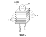
- the adsorption device 10B shown in FIG. 5C includes an adsorbent 11 and a medium path 51. As shown in FIG. In the adsorption device 10 ⁇ /b>B, the heat medium 52 that heats the adsorbent 11 may pass through the medium path 51 , and the cooling medium that cools the adsorbent 11 may pass through the medium path 51 .
- the adsorbent 11 provided in the adsorption device 10B typically has a sheet shape.
- the adsorption device 10B may or may not include a support for supporting the adsorbent 11 together with the adsorbent 11 .
- the adsorption device 10B is equipped with a plurality of adsorbents 11, for example.
- a plurality of adsorbents 11 may be arranged with a gap therebetween, and a gap between two adsorbents 11 may function as a ventilation path 14 .
- the configuration of the adsorbent 11 and the ventilation path 14 may be the same as the configuration described above for the structures 55A-55C.
- the medium path 51 is composed of, for example, a pipe made of metal such as copper, more specifically, a heat transfer pipe.
- the medium path 51 penetrates the adsorbent 11 in the thickness direction of the adsorbent 11, for example.
- a through hole is formed through the adsorbent 11 in the thickness direction, and the medium path 51 is inserted into the through hole of the adsorbent 11 .
- the adsorption device 10B typically has a structure similar to a fin-tube heat exchanger including heat transfer fins and heat transfer tubes passing through the heat transfer fins.
- the medium path 51 has a U-shape and may be inserted into two through holes formed in the adsorbent 11 .
- the number of through-holes formed in the adsorbent 11 and the number of medium paths 51 are not limited to those shown in FIG. 5C.
- four or more through-holes may be formed in the adsorbent 11
- two or more U-shaped medium paths 51 may be inserted into the through-holes of the adsorbent 11 .
- the adsorption device 10B further includes a casing (not shown) that houses the adsorbent 11 and the medium path 51.
- the casing has, for example, a regeneration gas inlet for sending regeneration gas to the interior of the casing.
- the casing may further have a desorbed gas outlet or the like for discharging desorbed gas from the adsorbent 11 to the outside of the casing.
- the casing may have a medium inlet for sending the heat medium 52 and the cooling medium to the medium path 51 and a medium outlet for discharging the heat medium 52 and the cooling medium from the medium path 51 .
- a medium path 51 is formed between two adsorbents 11 in the adsorption device 10C shown in FIG. 5D. Specifically, in the adsorption device 10 ⁇ /b>C, some of the gaps formed between the adsorbents 11 function as the medium paths 51 , and the remaining gaps function as the ventilation paths 14 .
- the medium paths 51 and the ventilation paths 14 are alternately arranged along the arrangement direction of the plurality of adsorbents 11 .
- the adsorption device 10C typically has a structure similar to a plate heat exchanger in which a plurality of heat transfer plates are stacked.
- the adsorption device 10C preferably includes a support for supporting the adsorbent 11 together with the adsorbent 11 .
- the adsorbent 11 faces the ventilation path 14 and the support faces the medium path 51 .
- a spacer 53 is arranged in the ventilation path 14, and a spacer (not shown) is arranged in the medium path 51 as well. These spacers are configured to secure the vent path 14 and the media path 51, to introduce the appropriate fluid to each path, and to prevent fluid from leaking to the other paths.
- the ventilation path 14 is connected to the external space of the adsorption device 10C at the back and front of the paper, thereby allowing regeneration gas to be taken into the ventilation path 14 from the external space. may have been
- the adsorption device 10C further includes a restraining member 56 that restrains the plurality of adsorbents 11.
- the restraining member 56 has, for example, a pair of plate members 57a and 57b, a rod 58 and a fixing member 59. As shown in FIG.
- the plate members 57 a and 57 b are arranged in the arrangement direction of the plurality of adsorbents 11 and sandwich the plurality of adsorbents 11 .
- the plate members 57a and 57b can apply pressure to the plurality of adsorbents 11 in the arrangement direction.
- the plate members 57a and 57b may be formed with the regeneration gas inlet, the medium inlet, the medium outlet, etc. described above for the adsorption device 10C.
- a through hole is formed in each of the plate members 57a and 57b, and the rod 58 is inserted into the through hole of the plate members 57a and 57b.
- the rod 58 may be a bolt having a male thread on its side surface.
- the fixing member 59 fixes one of the plate members 57a and 57b and the rod 58 to each other, for example.
- Fixing member 59 is typically a nut having an internal thread that can be screwed onto rod 58 .
- the restraining member 56 has a fixing member 59a that fixes the plate member 57a and the rod 58 to each other, and a fixing member 59b that fixes the plate member 57b and the rod 58 to each other.
- each of the two rods 58 is fixed by a fixing member 59.
- the number of rods 58 and the like are not limited to the example in FIG. 5D.
- the membrane separation device 20 may be a spiral membrane element, a hollow fiber membrane element, or the like.
- FIG. 6 shows a spiral membrane element.
- a membrane separation device 25 in FIG. 6 includes a central tube 26 and a laminate 27 .
- a laminate 27 includes the separation membrane 21 .
- the central tube 26 has a cylindrical shape. A plurality of holes or slits are formed on the surface of the central tube 26 to allow permeating gas to flow into the central tube 26 .
- materials for the central tube 26 include resins such as acrylonitrile-butadiene-styrene copolymer resin (ABS resin), polyphenylene ether resin (PPE resin), and polysulfone resin (PSF resin); and metals such as stainless steel and titanium. be done.
- the inner diameter of the central tube 26 is, for example, in the range of 20-100 mm.
- the laminate 27 further includes a feed-side channel material 28 and a permeate-side channel material 29 in addition to the separation membrane 21 .
- Laminate 27 is wound around central tube 26 .
- the membrane separation device 25 may further include an exterior material (not shown).
- a resin made of polyethylene, polypropylene, polyethylene terephthalate (PET), polyphenylene sulfide (PPS), or ethylene-chlorotrifluoroethylene copolymer (ECTFE) is used as the feed-side channel material 28 and the permeate-side channel material 29, for example.
- a resin made of polyethylene, polypropylene, polyethylene terephthalate (PET), polyphenylene sulfide (PPS), or ethylene-chlorotrifluoroethylene copolymer (ECTFE) is used as the feed-side channel material 28 and the permeate-side channel material 29, for example.
- ECTFE ethylene-chlorotrifluoroethylene copolymer
- Membrane separation using the membrane separation device 25 is performed, for example, by the following method.
- the desorption gas 61 is supplied to one end of the wound laminate 27 .
- the permeated gas for example, the first gas 62
- the permeated gas is discharged outside through the central tube 26 .
- a non-permeating gas for example, the second gas 63
- the separation membrane 21 is discharged to the outside from the other end of the wound laminate 27 .
- the heat exchanger 70 cools the second gas 63 discharged from the membrane separation device 20.
- the heat exchanger 70 is, for example, a gas-liquid heat exchanger that causes heat exchange between a cooling medium such as antifreeze and the second gas 63, and is typically a fin-tube heat exchanger.
- a heat pump equipped with a heat exchanger 70 or a cooling tower may be arranged in the second gas supply path 32 .
- the temperature of the second gas 63 supplied to the adsorption device 10 can be sufficiently lowered.
- the adsorbent 11 can easily adsorb the acid gas contained in the second gas 63 .
- the recovery system 120 of Embodiment 3 further includes a source gas supply path 35 . Except for the above, the configuration of the recovery system 120 is the same as the configuration of the recovery system 100 of the first embodiment.
- the source gas supply path 35 is connected to the second gas supply path 32 at the connection position 43 and is a path for sending the source gas containing the acid gas to the second gas supply path 32 .
- the raw material gas supply path 35 is connected to, for example, a tank (not shown) storing the raw material gas.
- the raw material gas is preferably the atmosphere. Therefore, the raw material gas supply path 35 may have an air intake (not shown) open to the atmosphere, and the air is continuously supplied to the second gas supply path 32 from the air intake. may be
- the raw material gas preferably contains, for example, an acidic gas and further contains other gases other than the acidic gas.
- the acid gas contained in the raw material gas is the same as the acid gas contained in the second gas 63, for example.
- the raw material gas is preferably the atmosphere.
- the source gas may be combustion gas or the like.
- the acid gas content in the raw material gas is not particularly limited, and is, for example, 0.01 vol% (100 volppm) or more, preferably 0.04 vol% (400 volppm) or more, and may be 0.1 vol% or more. .
- the upper limit of the acid gas content in the raw material gas is not particularly limited, and is, for example, 20 vol %.
- the source gas pressure is typically equal to the atmospheric pressure in the environment in which the recovery system 100 is used.
- the raw material gas preferably has a lower temperature than the second gas 63 sent from the membrane separation device 20 to the connection position 43 .
- the temperature of the second gas 63 can be easily lowered by mixing the raw material gas having a low temperature with the second gas 63.
- the temperature of the raw material gas is, for example, about room temperature (25° C.).
- the heat exchanger 71 cools the desorption gas 61 discharged from the adsorption device 10.
- the heat exchanger 71 is, for example, a gas-liquid heat exchanger that causes heat exchange between a cooling medium such as antifreeze and the desorbed gas 61, and is typically a fin-tube heat exchanger.
- a heat pump or cooling tower having a heat exchanger 71 may be arranged in the desorbed gas supply path 31 .
- the temperature of the desorbed gas 61 supplied to the membrane separation device 20 can be further lowered. Thereby, deterioration of the separation membrane 21 due to heat can be further suppressed.
- ⁇ Embodiment 5> As shown in FIG. 7D , in the recovery system 140 of Embodiment 5, a dehumidifier 75 that reduces the content of water in the desorbed gas 61 is arranged in the desorbed gas supply path 31 . Except for the above, the configuration of the recovery system 140 is the same as the configuration of the recovery system 100 of the first embodiment.
- the dehumidifier 75 reduces the content of water in the desorbed gas 61 discharged from the adsorption device 10.
- the dehumidifier 75 may be of a compressor type, a desiccant type, or a membrane type.
- the dehumidifier 75 the content of water in the desorbed gas 61 can be sufficiently reduced, and, for example, the vapor pressure can be adjusted below the saturated water vapor pressure. Thereby, it is possible to suppress the occurrence of dew condensation on the surface of the separation membrane 21, and it is possible to suppress the deterioration of the separation performance of the separation membrane 21 due to the dew condensation.
- the humidity of the desorption gas 61 is preferably adjusted to approximately 50% RH by the dehumidifier 75 .
- the desorbed gas 61 with this degree of humidity is suitable for suppressing deterioration of the separation performance of the separation membrane 21 .
- the dehumidifier 75 may be arranged in the regeneration gas supply path 30 .
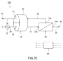
- ⁇ Embodiment 6> As shown in FIG. 7E , in the recovery system 150 of Embodiment 6, a heat exchanger 72 is arranged in the regeneration gas supply path 30 . Except for the above, the configuration of the recovery system 150 is the same as the configuration of the recovery system 100 of the first embodiment.
- the heat exchanger 72 appropriately adjusts the temperature of the regeneration gas 60 by cooling or heating the regeneration gas 60 supplied to the adsorption device 10 .
- the heat exchanger 72 is, for example, a gas-liquid heat exchanger that causes heat exchange between a cooling medium such as antifreeze or a heat medium such as hot water and the regeneration gas 60, and is typically a fin-tube heat exchanger. Exchanger.
- a heat pump equipped with a heat exchanger 72 or a cooling tower may be arranged in the regeneration gas supply path 30 .
- the temperature of the regeneration gas 60 supplied to the adsorption device 10 can be adjusted appropriately. As a result, the acidic gas can be sufficiently desorbed from the adsorbent 11, and deterioration of the adsorbent 11 due to heat can be suppressed.
- the temperature of the regeneration gas 60 may be, for example, 150°C or higher, particularly about 200°C.
- the heat energy received by the heat medium of the heat exchanger 72 is used for other purposes (for example, keeping water heated by a boiler warm). You can also
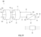
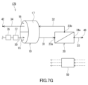
- ⁇ Embodiment 7> As shown in FIG. 7F , in the recovery system 160 of Embodiment 7, a rotary heat exchanger 73 is arranged in the regeneration gas supply path 30 . Except for the above, the configuration of the recovery system 160 is the same as the configuration of the recovery system 100 of the first embodiment.
- the rotary heat exchanger 73 is positioned in the regeneration gas supply path 30 and is positioned in a first zone 73a through which the regeneration gas 60 passes, and is positioned in the third gas discharge path 34 and is positioned in a second zone 73a through which the third gas 64 passes.
- zone 73b the rotary heat exchanger 73 has a heat exchange member and a tubular (especially cylindrical) case that houses the heat exchange member, and the inside of the case includes a first zone 73a and a There is a second zone 73b.
- the heat exchange member alternately moves between the first zone 73a and the second zone 73b by rotating the cylindrical case.
- the number of rotations of the case can be appropriately adjusted according to the size of the case and the characteristics of the heat exchange member, and is, for example, 0.5 rph to 10 rph.
- the heat exchange member contacts the regeneration gas 60 and receives thermal energy from the regeneration gas 60 . Thereby, the temperature of the regeneration gas 60 can be lowered. Furthermore, in the second zone 73b, the heat exchange member comes into contact with the third gas 64 and gives the third gas 64 thermal energy. This cools the heat exchange member.
- the combustion gas can be used as the regeneration gas 60 to recover the acid gas more efficiently.
- the heat exchange member of the rotary heat exchanger 73 is typically a honeycomb structure made of metal such as aluminum.
- the impurity treatment device 76 is a device for removing solid impurities from the regeneration gas 60, and includes, for example, a cleaning dust collector, a filtration dust collector, an electric dust collector, and the like.
- Examples of the corrosive substance treatment device 77 include a wet recovery device, a dry recovery device, and a catalyst device containing a catalyst for removing corrosive substances from the regeneration gas 60 .
- Solid impurities and corrosive substances can be removed from the regeneration gas 60 by the impurity treatment device 76 and the corrosive substance treatment device 77 . As a result, it is possible to prevent solid impurities and corrosive substances from coming into contact with the adsorbent 11 and deteriorating the adsorption performance of the adsorbent 11 .
- the recovery system 180 of Embodiment 9 further comprises a recycling path 36 . Except for the above, the configuration of the recovery system 180 is the same as the configuration of the recovery system 100 of the first embodiment.
- the recycling path 36 is a path that is connected to the regeneration gas supply path 30 and the desorbed gas supply path 31 and sends a part of the desorbed gas 61 from the desorbed gas supply path 31 to the regeneration gas supply path 30 .
- the recycling path 36 branches off from the desorbed gas supply path 31 at a branch position 44 and joins the regeneration gas supply path 30 at a junction position 45 .
- a part of the desorbed gas 61 can be sent to the regeneration gas supply path 30 according to the recycling path 36 .
- This desorbed gas 61 is mixed with the regeneration gas 60 in the regeneration gas supply path 30 .
- This increases the acid gas content in the regeneration gas 60 .
- the acid gas content in the desorbed gas 61 discharged from the adsorption device 10 also increases.
- the desorbed gas 61 can be sent to the membrane separation device 20 after the acid gas content in the desorbed gas 61 is sufficiently increased. Thereby, in the membrane separation device 20, the acid gas content in the first gas 62 can be easily increased.
- the recycling path 36 is also suitable for suppressing changes in the composition of the desorbed gas 61 over time.
- the adsorption device 10 includes a first storage portion 10a that stores the adsorbent 11a and a second storage portion 10b that stores the additional adsorbent 11b. have.
- Each of the regeneration gas supply path 30, the desorbed gas supply path 31, and the second gas supply path 32 has a portion connected to the first accommodation portion 10a and a portion connected to the second accommodation portion 10b.
- Recovery system 190 includes two third gas discharge paths 34a and 34b. Except for the above, the configuration of the recovery system 190 is the same as the configuration of the recovery system 100 of the first embodiment.
- the first storage part 10a is, for example, a tank that stores the adsorbent 11a.
- the shape of the adsorbent 11a is not particularly limited, and may be block-shaped, sheet-shaped, filter-shaped, particulate-shaped, or the like. In the present specification, particulate includes spherical, ellipsoidal, scaly, fibrous and the like.
- the second storage part 10b is, for example, a tank that stores an additional adsorbent 11b. The composition and shape of the additional adsorbent 11b may be the same as or different from the adsorbent 11a.
- the regeneration gas supply path 30 has a first portion 30a and a second portion 30b.
- the first portion 30a is connected to the regeneration gas inlet of the first accommodation portion 10a and is a path for supplying the regeneration gas to the first accommodation portion 10a.
- the second portion 30b branches off from the first portion 30a at a branch position 46 and is connected to the regeneration gas inlet of the second containing portion 10b.
- the second portion 30b is a path for supplying the regeneration gas to the second accommodating portion 10b.
- a valve (not shown) may be arranged at the branch position 46 for adjusting the flow rate of the regeneration gas sent to the first storage section 10a and the second storage section 10b. Specific examples of valves are on-off valves and flow control valves.
- the desorption gas supply path 31 has a first portion 31a and a second portion 31b.
- the first portion 31a is connected to the desorbed gas outlet of the first containing portion 10a and is a path for supplying the desorbed gas from the first containing portion 10a to the membrane separation device 20.
- the second portion 31b is connected to the desorbed gas outlet of the second containing portion 10b, and joins the first portion 31a at the confluence position 47.
- the second portion 31b is a path for supplying the desorption gas from the second housing portion 10b to the first portion 31a.
- a valve (not shown) for adjusting the flow rate of the desorbed gas discharged from the first storage portion 10a and the second storage portion 10b may be arranged at the confluence position 47 .
- Specific examples of valves are on-off valves and flow control valves.
- the second gas supply path 32 has a first portion 32a and a second portion 32b.
- the first portion 32a is connected to the second gas inlet of the second containing portion 10b and is a path for supplying the second gas from the membrane separation device 20 to the second containing portion 10b.
- the second portion 32b branches off from the first portion 32a at a branching position 48 and is connected to the second gas inlet of the first containing portion 10a.
- the second portion 32b is a path for supplying the second gas to the first containing portion 10a.
- a valve (not shown) may be arranged at the branch position 48 for adjusting the flow rate of the second gas sent to the first storage section 10a and the second storage section 10b. Specific examples of valves are on-off valves and flow control valves.
- the third gas discharge path 34a is connected to the third gas outlet of the second storage section 10b and is a path for discharging the third gas from the second storage section 10b.
- An opening (discharge port 42a) for discharging the third gas from the third gas discharge path 34a is formed in the third gas discharge path 34a.
- the third gas discharge path 34b is connected to the third gas outlet of the first housing portion 10a and is a path for discharging the third gas from the first housing portion 10a.
- An opening (discharge port 42b) for discharging the third gas from the third gas discharge path 34b is formed in the third gas discharge path 34b.
- the third gas exhaust path 34b may join the third gas exhaust path 34a.
- the recovery system 190 includes a first operation in which the regeneration gas is sent to the first storage section 10a and the second gas is sent to the second storage section 10b, and a second operation in which the second gas is sent to the first storage section 10a and the second storage section
- a switching mechanism for switching between a second operation of sending regeneration gas to 10b is further provided.
- the switching mechanism includes, for example, valves arranged at each of branch position 46 , merge position 47 and branch position 48 , and controller 50 .
- the first operation and the second operation can be switched by controlling each valve with the controller 50 and switching the path along which the gas moves.
- the recovery method of acid gas using the recovery system 190 can be performed, for example, by the following method.
- a first operation is performed in which the regeneration gas is sent to the first container 10a and the second gas is sent to the second container 10b.
- the valve arranged at the branch position 46 and the valve arranged at the confluence position 47 are controlled to regenerate only the first accommodation portion 10a out of the first accommodation portion 10a and the second accommodation portion 10b.
- Supply gas Further, the valve arranged at the branch position 48 is controlled to supply the second gas only to the second accommodation portion 10b of the first accommodation portion 10a and the second accommodation portion 10b.
- the regeneration gas is supplied to the first housing portion 10a through the first portion 30a of the regeneration gas supply path 30.
- the desorbed gas discharged from the first housing portion 10 a is supplied to the first chamber 23 (supply side space) of the membrane separation device 20 through the desorbed gas supply path 31 .
- the above separation process is performed in the membrane separation device 20 .
- the second gas discharged from the membrane separation device 20 is supplied through the first portion 32a of the second gas supply path 32 to the second storage portion 10b.
- the above suction step is performed in the second housing portion 10b.
- the third gas discharged from the second housing portion 10b is discharged from the discharge port 42a through the third gas discharge path 34a.
- the duration of the first operation is not particularly limited, and is, for example, 0.5 hours to 24 hours.
- the first operation is performed, for example, until the adsorbent 11a accommodated in the first accommodation portion 10a is sufficiently regenerated.
- a second operation is performed in which the second gas is sent to the first accommodation portion 10a and the regeneration gas is sent to the second accommodation portion 10b.
- the valve arranged at the branch position 46 and the valve arranged at the confluence position 47 are controlled to regenerate only the second accommodation portion 10b out of the first accommodation portion 10a and the second accommodation portion 10b.
- the valve arranged at the branch position 48 is controlled to supply the second gas only to the first accommodation portion 10a of the first accommodation portion 10a and the second accommodation portion 10b.
- the regeneration gas is supplied to the second housing portion 10b through the second portion 30b of the regeneration gas supply path 30.
- the desorbed gas discharged from the second housing portion 10b is supplied to the first chamber 23 (supply side space) of the membrane separation device 20 through the desorbed gas supply path 31 .
- the above separation process is performed in the membrane separation device 20 .
- the second gas discharged from the membrane separation device 20 is supplied through the second portion 32b of the second gas supply path 32 to the first storage portion 10a.
- the above adsorption step is performed in the first housing portion 10a.
- the third gas discharged from the first accommodation portion 10a is discharged from the discharge port 42b through the third gas discharge path 34b.
- the duration of the second operation is not particularly limited, and is, for example, 0.5 hours to 24 hours.
- the second operation is performed, for example, until the adsorbent 11b accommodated in the second accommodation portion 10b is sufficiently regenerated.
- the recovery system 190 is suitable for batch operation. However, in the recovery system 190, the acid gas can be continuously recovered by alternately repeating the first operation and the second operation.
- the recovery system 190 has an advantage that it is easy to apply various shapes of adsorbents such as particles as the adsorbents 11a and 11b.
- the structure 55A described with reference to FIG. 2, the structure 55B described with reference to FIG. 5A, or the structure 55C described with reference to FIG. may Similarly, the second accommodation portion 10b may accommodate the structure 55A, the structure 55B, or the structure 55C.
- the adsorption device 10B described with reference to FIG. 5C and the adsorption device 10C described with reference to FIG. 5D can also be used as the first housing portion 10a.
- the adsorption device 10B or the adsorption device 10C can also be used as the second accommodation portion 10b.
- each of the first accommodation portion 10a and the second accommodation portion 10b may be the adsorption device 10B.
- the temperature of the adsorbent 11 can be appropriately adjusted by passing a heat medium or a cooling medium through the medium path 51 of each adsorption device 10B.
- the life of the adsorbent 11 is shortened by cooling the adsorbent 11 by passing a cooling medium through the medium path 51 of the adsorption device 10B to which the regeneration gas is sent. shortening can be suppressed.
- the acid gas contained in the second gas is adsorbed by the adsorbent 11. It is possible to reduce the influence of heat generation.
- the recovery system 200 has the same configuration as the recovery system 150 (FIG. 7E) of Embodiment 6, except that the adsorption device 10 is not provided.
- the recovery system 200 includes a membrane separator 220 , a combustion gas supply line 230 , a first gas discharge line 233 and a second gas discharge line 232 .
- the membrane separation device 220 has a separation membrane, and the separation membrane separates the combustion gas into a first gas having a higher acid gas content than the combustion gas and a first gas having a lower acid gas content than the combustion gas. and the second gas.
- the combustion gas supply route 230 is a route for supplying combustion gas to the membrane separation device 220 .
- a heat exchanger 272 for cooling the combustion gas is arranged in the combustion gas supply path 230 .
- the first gas discharge route 233 is connected to the first gas outlet of the membrane separation device 220 and is a route for discharging the first gas from the membrane separation device 220 .
- a discharge port 240 for discharging the first gas from the first gas discharge path 233 is formed in the first gas discharge path 233 .
- the second gas discharge route 232 is connected to the second gas outlet of the membrane separation device 220 and is a route for discharging the second gas from the membrane separation device 220 .
- a discharge port 242 for discharging the second gas from the second gas discharge path 232 is formed in the second gas discharge path 232 .
- the carbon dioxide permeation rate was set to 100 GPU
- the nitrogen permeation rate was set to 2.5 GPU
- the membrane area was set to 350 m 2 .
- GPU means 10 ⁇ 6 ⁇ cm 3 (STP)/(sec ⁇ cm 2 ⁇ cmHg).
- cm 3 (STP) means the volume of gas at 1 atmosphere and 0°C.
- the above permeation rate was assumed to be the value specified by the following test method.
- Test A mixed gas containing carbon dioxide and nitrogen is supplied to the space adjacent to one side of the separation membrane, and an operation (separation operation) is performed to reduce the pressure in the space adjacent to the other side of the separation membrane.
- a permeation rate is determined based on the results of the separation operation.
- the content of carbon dioxide in the mixed gas is 50 vol% in the standard state (0 ° C., 101 kPa)
- the mixed gas supplied to the space adjacent to one surface has a temperature of 30 ° C. and the pressure is 0.1 MPa
- the space adjacent to the other surface is decompressed so that the pressure in the space is 0.1 MPa lower than the atmospheric pressure in the measurement environment.
- a volume ratio is a value in a standard state (0 degreeC, 101 kPa).
- the first gas had a flow rate of 7.8 Sm 3 /h, a CO 2 /N 2 volume ratio of 70/30, and a temperature of 50°C.
- the second gas had a flow rate of 92.2 Sm 3 /h, a CO 2 /N 2 volume ratio of 4/96, and a temperature of 50°C. From this result, it can be seen that in Calculation Example 1, carbon dioxide can be recovered with a recovery rate of 61% by recovering the first gas. Furthermore, in calculation example 1, the power consumption of the heat exchanger 272 was 1.06 kW.
- this amount of heat matches the power consumption of the heat exchanger 272 obtained in the first calculation example.
- the adsorbent provided in the adsorption device 10 one having a heat of adsorption of 80 kJ/mol when adsorbing 1 mol of carbon dioxide was assumed.
- An example of an adsorbent that exhibits a heat of adsorption of about 80 kJ/mol is polyethyleneimine.
- the second gas is cooled to 30° C. by the heat exchanger 70 .
- the desorbed gas from the adsorption device 10 had a flow rate of 101.1 Sm 3 /h, a CO 2 /N 2 volume ratio of 10/90, and a temperature of 50°C. Ta.
- the first gas (permeation gas) had a flow rate of 8.5 Sm 3 /h, a CO 2 /N 2 volume ratio of 72/28, and a temperature of 50°C.
- the second gas (non-permeable gas) had a flow rate of 92.6 Sm 3 /h, a CO 2 /N 2 volume ratio of 4/96, and a temperature of 50°C.
- the second gas was cooled from 50° C. to 30° C. by the heat exchanger 70 .
- the third gas discharged from the adsorption device 10 had a flow rate of 91.5 Sm 3 /h, a CO 2 /N 2 volume ratio of 3/97, and a temperature of 63°C.
- the recovery system of the present embodiment in which the adsorption device and the membrane separation device are combined, compared to the case where only the membrane separation device is used, the power consumption is suppressed and the recovery rate is high. It turns out that acid gas can be collect
- the recovery system of this embodiment is suitable for efficiently recovering acid gas.
- the recovery system of this embodiment is suitable for recovering acid gases, especially carbon dioxide.
Landscapes
- Chemical & Material Sciences (AREA)
- Engineering & Computer Science (AREA)
- Analytical Chemistry (AREA)
- General Chemical & Material Sciences (AREA)
- Oil, Petroleum & Natural Gas (AREA)
- Chemical Kinetics & Catalysis (AREA)
- Separation Using Semi-Permeable Membranes (AREA)
- Separation Of Gases By Adsorption (AREA)
- Treating Waste Gases (AREA)
Abstract
Description
酸性ガスを吸着している状態で、再生ガスと接触して前記酸性ガスを脱離させる吸着材を有し、かつ、前記再生ガスと前記酸性ガスとを含む脱離ガスを放出する吸着装置と、
前記脱離ガスを、前記脱離ガスよりも前記酸性ガスの含有率が高い第1ガスと、前記脱離ガスよりも前記酸性ガスの含有率が低い第2ガスとに分離する分離膜を有する膜分離装置と、
を備えた、酸性ガスの回収システムを提供する。
酸性ガスを吸着している吸着材を再生ガスと接触させて、前記吸着材から前記酸性ガスを脱離させることと、
前記再生ガスと前記酸性ガスとを含む脱離ガスを分離膜で分離することによって、前記脱離ガスよりも前記酸性ガスの含有率が高い第1ガスと、前記脱離ガスよりも前記酸性ガスの含有率が低い第2ガスとに分離することと、
を含む、酸性ガスの回収方法を提供する。
酸性ガスを吸着している状態で、再生ガスと接触して前記酸性ガスを脱離させる吸着材を有し、かつ、前記再生ガスと前記酸性ガスとを含む脱離ガスを放出する吸着装置と、
前記脱離ガスを、前記脱離ガスよりも前記酸性ガスの含有率が高い第1ガスと、前記脱離ガスよりも前記酸性ガスの含有率が低い第2ガスとに分離する分離膜を有する膜分離装置と、
を備える。
酸性ガスを吸着している吸着材を再生ガスと接触させて、前記吸着材から前記酸性ガスを脱離させることと、
前記再生ガスと前記酸性ガスとを含む脱離ガスを分離膜で分離することによって、前記脱離ガスよりも前記酸性ガスの含有率が高い第1ガスと、前記脱離ガスよりも前記酸性ガスの含有率が低い第2ガスとに分離することと、
を含む。
[回収システム]
図1に示すように、実施形態1の酸性ガスの回収システム100は、吸着材を有する吸着装置10と、分離膜を有する膜分離装置20とを備える。吸着装置10において、吸着材は、酸性ガスを吸着している状態で、再生ガスと接触して酸性ガスを脱離させる。酸性ガスを脱離させることによって、吸着材が再生する。吸着装置10は、再生ガスと、吸着材から脱離した酸性ガスとを含む脱離ガスを放出する。
図2に示すとおり、吸着装置10(吸着装置10A)は、吸着材11と、吸着材11を収容しているケース17とを有している。詳細には、吸着材11を備え、さらに通気経路14を有する構造体55Aがケース17に収容されている。上述のとおり、ケース17は、筒状(特に円筒状)である。通気経路14は、ケース17の長手方向に延びており、再生ガス60又は第2ガス63が通過する経路として機能する。構造体55Aは、典型的には、同じ方向に延びている複数の通気経路14を有するハニカム構造体である。
吸着材11は、再生ガスと接触したときに酸性ガスを脱離させることができ、第2ガスと接触したときに、第2ガスに含まれる酸性ガスを吸着することができる限り、特に限定されない。吸着材11は、温度スイング吸着法に適したものであることが好ましい。一例として、吸着材11は、室温(25℃)程度で酸性ガスを吸着することができ、かつ、再生ガスから熱エネルギーを受け取って、酸性ガスを脱離させることができる。
図3に示すとおり、膜分離装置20は、分離膜21及びタンク22を備える。タンク22は、第1室23及び第2室24を有する。第1室23内の空間が供給側空間に相当し、第2室24内の空間が透過側空間に相当する。分離膜21は、タンク22の内部に配置されている。タンク22の内部において、分離膜21は、第1室23と第2室24とを隔てている。分離膜21は、タンク22の1対の壁面の一方から他方まで延びている。
分離膜21は、例えば、脱離ガス61に含まれる酸性ガスを優先的に透過させることができる。ただし、分離膜21は、脱離ガス61に含まれる酸性ガス以外の他のガスを優先的に透過させてもよい。以下では、一例として、脱離ガス61に含まれる酸性ガス、特に二酸化炭素、を優先的に透過させることができる分離膜21について説明する。
分離機能層1は、脱離ガス61に含まれる酸性ガスを優先的に透過させることができる層である。好ましい一形態では、分離機能層1は、樹脂を含む。分離機能層1に含まれる樹脂としては、例えば、ポリエーテルブロックアミド樹脂、ポリアミド樹脂、ポリエーテル樹脂、ポリイミド樹脂、酢酸セルロース樹脂、シリコーン樹脂及びフッ素樹脂が挙げられる。分離機能層1は、好ましくはポリエーテルブロックアミド樹脂を含む。この形態において、分離機能層1は、好ましくは、実質的に樹脂からなる。本明細書において、「実質的に~からなる」は、言及された材料の本質的特徴を変更する他の成分を排除することを意味し、例えば95wt%以上、さらには99wt%以上が当該材料により構成されていることを意味する。
中間層2は、例えば、樹脂を含み、樹脂(マトリクス)に分散したナノ粒子をさらに含んでいてもよい。ナノ粒子は、マトリクス内で互いに離間していてもよく、部分的に凝集していてもよい。マトリクスの材料は、特に限定されず、例えば、ポリジメチルシロキサンなどのシリコーン樹脂;ポリテトラフルオロエチレンなどのフッ素樹脂;ポリエチレンオキシドなどのエポキシ樹脂;ポリイミド樹脂;ポリスルホン樹脂;ポリトリメチルシリルプロピン、ポリジフェニルアセチレンなどのポリアセチレン樹脂;ポリメチルペンテンなどのポリオレフィン樹脂が挙げられる。マトリクスは、シリコーン樹脂を含むことが好ましい。
多孔性支持体3は、中間層2を介して分離機能層1を支持する。多孔性支持体3としては、例えば、不織布;多孔質ポリテトラフルオロエチレン;芳香族ポリアミド繊維;多孔質金属;焼結金属;多孔質セラミック;多孔質ポリエステル;多孔質ナイロン;活性化炭素繊維;ラテックス;シリコーン;シリコーンゴム;ポリフッ化ビニル、ポリフッ化ビニリデン、ポリウレタン、ポリプロピレン、ポリエチレン、ポリスチレン、ポリカーボネート、ポリスルホン、ポリエーテルエーテルケトン、ポリアクリロニトリル、ポリイミド及びポリフェニレンオキシドからなる群より選ばれる少なくとも1つを含む透過性(多孔質)ポリマー;連続気泡又は独立気泡を有する金属発泡体;連続気泡又は独立気泡を有するポリマー発泡体;シリカ;多孔質ガラス;メッシュスクリーンなどが挙げられる。多孔性支持体3は、これらのうちの2種以上を組み合わせたものであってもよい。
本実施形態において、分離膜21は、典型的には平膜である。ただし、分離膜21は、平膜以外の形状であってもよく、例えば、中空糸膜であってもよい。一例として、中空糸膜としての分離膜21は、分離機能層1及び多孔性支持体3を備えている一方、中間層2を備えていなくてもよい。分離膜21が中空糸膜である場合、膜面積を増加させやすい傾向がある。
本実施形態において、酸性ガスの回収方法は、酸性ガスを吸着している吸着材11を再生ガス60と接触させて、吸着材11から酸性ガスを脱離させること(再生工程)と、再生ガスと酸性ガスとを含む脱離ガス61を分離膜21で分離することによって、脱離ガス61よりも酸性ガスの含有率が高い第1ガス62と、脱離ガス61よりも酸性ガスの含有率が低い第2ガス63とに分離すること(分離工程)と、を含む。
回収システム100において、吸着装置10が備える構造体55Aの形状は、図2に示したものに限定されない。例えば、図5Aに示す構造体55Bは、2つの吸着材11A及び11Bを有する複数の吸着材ユニットUが積層された形状を有する。このことを除き、構造体55Bの構成は、構造体55Aの構成と同じである。なお、説明のため、図5Aでは、ケース17が省略されている。
回収システム100において、吸着装置10が備える構造体は、上記の構造体55A及び55Bのようなハニカム構造体でなくてもよい。図5Bに示す構造体55Cは、吸着材11として、平板形状を有する吸着材11Bのみを備えている。詳細には、構造体55Cは、複数の吸着材11Bを備え、複数の吸着材11Bが空隙を介して並んでいる。2つの吸着材11Bの間の空隙が通気経路14として機能する。なお、説明のため、図5Bでは、ケース17が省略されている。
回収システム100が備える吸着装置10は、図1及び2で示したロータ式吸着装置でなくてもよい。図5Cに示す吸着装置10Bは、吸着材11と、媒体経路51とを備える。吸着装置10Bでは、吸着材11を加熱する熱媒体52が媒体経路51を通過してもよく、吸着材11を冷却する冷却媒体が媒体経路51を通過してもよい。
図5Dに示す吸着装置10Cでは、2つの吸着材11の間に媒体経路51が形成されている。詳細には、吸着装置10Cにおいて、複数の吸着材11の間に形成された複数の空隙のうち、一部の空隙が媒体経路51として機能し、残りの空隙が通気経路14として機能する。媒体経路51及び通気経路14は、複数の吸着材11の配列方向に沿って、交互に並んでいる。吸着装置10Cは、典型的には、複数の伝熱プレートが積層されたプレート式熱交換器と同様の構造を有している。
回収システム100において、膜分離装置20は、スパイラル型の膜エレメント、中空糸膜エレメントなどであってもよい。図6は、スパイラル型の膜エレメントを示している。図6の膜分離装置25は、中心管26及び積層体27を備えている。積層体27が分離膜21を含んでいる。
図7Aに示すとおり、本実施形態2の回収システム110において、第2ガス供給経路32には、第2ガス63を冷却する熱交換器70が配置されている。以上を除き、回収システム110の構成は、実施形態1の回収システム100の構成と同じである。したがって、実施形態1の回収システム100と本実施形態の回収システム110とで共通する要素には同じ参照符号を付し、それらの説明を省略することがある。すなわち、以下の各実施形態に関する説明は、技術的に矛盾しない限り、相互に適用されうる。さらに、技術的に矛盾しない限り、各実施形態は、相互に組み合わされてもよい。
図7Bに示すとおり、本実施形態3の回収システム120は、原料ガス供給経路35をさらに備える。以上を除き、回収システム120の構成は、実施形態1の回収システム100の構成と同じである。
図7Cに示すとおり、本実施形態4の回収システム130において、脱離ガス供給経路31には、脱離ガス61を冷却する熱交換器71が配置されている。以上を除き、回収システム130の構成は、実施形態1の回収システム100の構成と同じである。
図7Dに示すとおり、本実施形態5の回収システム140において、脱離ガス供給経路31には、脱離ガス61における水の含有率を低下させる除湿器75が配置されている。以上を除き、回収システム140の構成は、実施形態1の回収システム100の構成と同じである。
図7Eに示すとおり、本実施形態6の回収システム150において、再生ガス供給経路30には、熱交換器72が配置されている。以上を除き、回収システム150の構成は、実施形態1の回収システム100の構成と同じである。
図7Fに示すとおり、本実施形態7の回収システム160において、再生ガス供給経路30には、回転式熱交換器73が配置されている。以上を除き、回収システム160の構成は、実施形態1の回収システム100の構成と同じである。
図7Gに示すとおり、本実施形態8の回収システム170において、再生ガス供給経路30には、不純物処理装置76や腐食性物質処理装置77が配置されている。以上を除き、回収システム170の構成は、実施形態1の回収システム100の構成と同じである。
図7Hに示すとおり、本実施形態9の回収システム180は、リサイクル経路36をさらに備える。以上を除き、回収システム180の構成は、実施形態1の回収システム100の構成と同じである。
図7Iに示すように、本実施形態10の回収システム190において、吸着装置10は、吸着材11aを収容する第1収容部10aと、追加の吸着材11bを収容する第2収容部10bとを有する。再生ガス供給経路30、脱離ガス供給経路31及び第2ガス供給経路32は、それぞれ、第1収容部10aに接続された部分と、第2収容部10bに接続された部分とを有する。回収システム190は、2つの第3ガス排出経路34a及び34bを備える。以上を除き、回収システム190の構成は、実施形態1の回収システム100の構成と同じである。
Schlumberger社製のプロセスモデリングソフトSymmetryを用いて、図8に示す回収システム200を運転したときのシミュレーションを行った。回収システム200は、吸着装置10を備えていないことを除き、実施形態6の回収システム150(図7E)と同様の構成を有する。詳細には、回収システム200は、膜分離装置220、燃焼ガス供給経路230、第1ガス排出経路233、及び第2ガス排出経路232を備える。
試験:分離膜の一方の面に隣接する空間に、二酸化炭素及び窒素からなる混合ガスを供給するとともに、分離膜の他方の面に隣接する空間を減圧する操作(分離操作)を行う。分離操作の結果に基づいて、透過速度を特定する。ここで、分離操作において、混合ガスにおける二酸化炭素の含有率は、標準状態(0℃、101kPa)で50vol%であり、一方の面に隣接する空間に供給される混合ガスは、温度が30℃であり、圧力が0.1MPaであり、他方の面に隣接する空間は、当該空間内の圧力が測定環境における大気圧に対して0.1MPa小さくなるように減圧されている。
[燃焼ガスの供給条件]
流量:100.0Sm3/h
組成(体積比):CO2/N2=9/91
圧力:0.1013MPa
温度:80℃
[透過側空間]
圧力:0.001MPa
Schlumberger社製のプロセスモデリングソフトSymmetryを用いて、実施形態2の回収システム110(図7A)を運転したときのシミュレーションを行った。計算例2において、燃焼ガス(再生ガス)の供給条件、運転時における膜分離装置20の透過側空間の圧力、膜分離装置20が備える分離膜の特性、熱交換器70のCOPは、計算例1と同じものを想定した。吸着装置10が脱離工程(再生工程)で消費する熱量は、吸着材が二酸化炭素を脱離するときの吸熱反応に由来すると想定した。また、この熱量が計算例1で求めた熱交換器272の消費電力と一致することを想定した。吸着装置10が備える吸着材としては、1molの二酸化炭素を吸着したときの吸着熱が80kJ/molであるものを想定した。なお、80kJ/mol程度の吸着熱を示す吸着材としては、例えばポリエチレンイミンが挙げられる。また、計算例2では、熱交換器70により、第2ガスを30℃に冷却することを想定した。
Claims (15)
- 酸性ガスを吸着している状態で、再生ガスと接触して前記酸性ガスを脱離させる吸着材を有し、かつ、前記再生ガスと前記酸性ガスとを含む脱離ガスを放出する吸着装置と、
前記脱離ガスを、前記脱離ガスよりも前記酸性ガスの含有率が高い第1ガスと、前記脱離ガスよりも前記酸性ガスの含有率が低い第2ガスとに分離する分離膜を有する膜分離装置と、
を備えた、酸性ガスの回収システム。 - 前記吸着装置は、前記再生ガスが通過する再生ゾーンを有し、
前記再生ゾーンにおいて、前記吸着材は、前記再生ガスと接触して、前記酸性ガスを脱離させる、請求項1に記載の回収システム。 - 前記吸着装置は、前記第2ガスが通過する吸着ゾーンをさらに有し、
前記吸着ゾーンにおいて、前記吸着材は、前記第2ガスと接触して、前記第2ガスに含まれる前記酸性ガスを吸着する、請求項2に記載の回収システム。 - 前記吸着装置は、前記吸着材を前記再生ゾーンと前記吸着ゾーンとに交互に移動させる移動機構を有する、請求項3に記載の回収システム。
- 前記吸着装置は、前記吸着材を収容する第1収容部と、追加の吸着材を収容する第2収容部とを有する、請求項1に記載の回収システム。
- 前記第1収容部に前記再生ガスを送り、かつ前記第2収容部に前記第2ガスを送る第1運転と、前記第1収容部に前記第2ガスを送り、かつ前記第2収容部に前記再生ガスを送る第2運転と、を切り替える切替機構をさらに備えた、請求項5に記載の回収システム。
- 前記吸着装置及び前記膜分離装置に接続され、前記吸着装置から前記膜分離装置に前記脱離ガスを送るための脱離ガス供給経路をさらに備えた、請求項1~6のいずれか1項に記載の回収システム。
- 前記脱離ガス供給経路に配置され、前記脱離ガスにおける水の含有率を低下させる除湿器をさらに備えた、請求項7に記載の回収システム。
- 前記吸着装置に接続され、前記吸着装置に前記再生ガスを供給するための再生ガス供給経路と、
前記再生ガス供給経路及び前記脱離ガス供給経路に接続され、前記脱離ガス供給経路から前記再生ガス供給経路に前記脱離ガスの一部を送るためのリサイクル経路と、
をさらに備えた、請求項7に記載の回収システム。 - 前記吸着装置及び前記膜分離装置に接続され、前記膜分離装置から前記吸着装置に前記第2ガスを送るための第2ガス供給経路をさらに備えた、請求項1に記載の回収システム。
- 前記第2ガス供給経路に配置され、前記第2ガスを冷却する熱交換器をさらに備えた、請求項10に記載の回収システム。
- 前記第2ガス供給経路に接続され、酸性ガスを含む原料ガスを前記第2ガス供給経路に送るための原料ガス供給経路をさらに備えた、請求項10に記載の回収システム。
- 前記再生ガスは、対象物が燃焼することによって生じた燃焼ガスである、請求項1に記載の回収システム。
- 酸性ガスを吸着している吸着材を再生ガスと接触させて、前記吸着材から前記酸性ガスを脱離させることと、
前記再生ガスと前記酸性ガスとを含む脱離ガスを分離膜で分離することによって、前記脱離ガスよりも前記酸性ガスの含有率が高い第1ガスと、前記脱離ガスよりも前記酸性ガスの含有率が低い第2ガスとに分離することと、
を含む、酸性ガスの回収方法。 - 前記第2ガスを前記吸着材と接触させて、前記第2ガスに含まれる前記酸性ガスを前記吸着材に吸着させることをさらに含む、請求項14に記載の回収方法。
Priority Applications (4)
| Application Number | Priority Date | Filing Date | Title |
|---|---|---|---|
| US18/843,597 US20250177912A1 (en) | 2022-03-04 | 2023-03-01 | Acidic gas recovery system and recovery method |
| EP23763517.2A EP4487937A4 (en) | 2022-03-04 | 2023-03-01 | ACID GAS RECOVERY SYSTEM AND RECOVERY PROCESS |
| JP2024504736A JPWO2023167260A1 (ja) | 2022-03-04 | 2023-03-01 | |
| CN202380022588.8A CN118715053A (zh) | 2022-03-04 | 2023-03-01 | 酸性气体的回收系统及回收方法 |
Applications Claiming Priority (2)
| Application Number | Priority Date | Filing Date | Title |
|---|---|---|---|
| JP2022033320 | 2022-03-04 | ||
| JP2022-033320 | 2022-03-04 |
Publications (1)
| Publication Number | Publication Date |
|---|---|
| WO2023167260A1 true WO2023167260A1 (ja) | 2023-09-07 |
Family
ID=87883868
Family Applications (1)
| Application Number | Title | Priority Date | Filing Date |
|---|---|---|---|
| PCT/JP2023/007689 Ceased WO2023167260A1 (ja) | 2022-03-04 | 2023-03-01 | 酸性ガスの回収システム及び回収方法 |
Country Status (5)
| Country | Link |
|---|---|
| US (1) | US20250177912A1 (ja) |
| EP (1) | EP4487937A4 (ja) |
| JP (1) | JPWO2023167260A1 (ja) |
| CN (1) | CN118715053A (ja) |
| WO (1) | WO2023167260A1 (ja) |
Cited By (1)
| Publication number | Priority date | Publication date | Assignee | Title |
|---|---|---|---|---|
| WO2025127069A1 (ja) * | 2023-12-15 | 2025-06-19 | ダイキン工業株式会社 | 吸着ユニット、吸着装置、および二酸化炭素回収システム |
Citations (8)
| Publication number | Priority date | Publication date | Assignee | Title |
|---|---|---|---|---|
| US7575624B2 (en) * | 2006-12-19 | 2009-08-18 | Uop Pllc | Molecular sieve and membrane system to purify natural gas |
| JP2014533195A (ja) | 2011-10-06 | 2014-12-11 | ビーエーエスエフ コーポレーション | 基体、担体および/または担体コーティング基体の上に収着剤を塗布する方法 |
| JP2016117052A (ja) * | 2014-12-19 | 2016-06-30 | 株式会社西部技研 | 吸収式除去・濃縮装置 |
| JP6186286B2 (ja) | 2014-01-16 | 2017-08-23 | 富士フイルム株式会社 | 酸性ガス分離用積層体の製造方法、酸性ガス分離用積層体および酸性ガス分離モジュール |
| JP2019155301A (ja) * | 2018-03-15 | 2019-09-19 | 東邦瓦斯株式会社 | ガス回収濃縮装置およびガス回収濃縮方法 |
| JP2021133323A (ja) * | 2020-02-28 | 2021-09-13 | 株式会社西部技研 | ガス分離回収装置 |
| WO2022014652A1 (ja) * | 2020-07-15 | 2022-01-20 | 日東電工株式会社 | 調湿システム、吸脱着装置、調湿装置及び調湿方法 |
| JP2022127004A (ja) * | 2021-02-19 | 2022-08-31 | パナソニックIpマネジメント株式会社 | 二酸化炭素分離装置、及びその運転方法 |
Family Cites Families (5)
| Publication number | Priority date | Publication date | Assignee | Title |
|---|---|---|---|---|
| EP2141119B1 (en) * | 2007-03-29 | 2014-01-22 | Nippon Oil Corporation | Method of hydrogen production and carbon dioxide recovery and apparatus therefor |
| US8388732B2 (en) * | 2010-06-25 | 2013-03-05 | Uop Llc | Integrated membrane and adsorption system for carbon dioxide removal from natural gas |
| GB2486476A (en) * | 2010-12-16 | 2012-06-20 | Doosan Power Systems Ltd | Method and apparatus for the regeneration of a capture medium |
| EP2540377A1 (en) * | 2011-06-29 | 2013-01-02 | Alstom Technology Ltd | A method of cleaning a carbon dioxide rich flue gas |
| KR101986776B1 (ko) * | 2016-04-07 | 2019-06-07 | (주)에어레인 | 흡착-분리막 복합공정을 이용한 바이오가스 정제방법 |
-
2023
- 2023-03-01 EP EP23763517.2A patent/EP4487937A4/en active Pending
- 2023-03-01 JP JP2024504736A patent/JPWO2023167260A1/ja active Pending
- 2023-03-01 WO PCT/JP2023/007689 patent/WO2023167260A1/ja not_active Ceased
- 2023-03-01 US US18/843,597 patent/US20250177912A1/en active Pending
- 2023-03-01 CN CN202380022588.8A patent/CN118715053A/zh active Pending
Patent Citations (8)
| Publication number | Priority date | Publication date | Assignee | Title |
|---|---|---|---|---|
| US7575624B2 (en) * | 2006-12-19 | 2009-08-18 | Uop Pllc | Molecular sieve and membrane system to purify natural gas |
| JP2014533195A (ja) | 2011-10-06 | 2014-12-11 | ビーエーエスエフ コーポレーション | 基体、担体および/または担体コーティング基体の上に収着剤を塗布する方法 |
| JP6186286B2 (ja) | 2014-01-16 | 2017-08-23 | 富士フイルム株式会社 | 酸性ガス分離用積層体の製造方法、酸性ガス分離用積層体および酸性ガス分離モジュール |
| JP2016117052A (ja) * | 2014-12-19 | 2016-06-30 | 株式会社西部技研 | 吸収式除去・濃縮装置 |
| JP2019155301A (ja) * | 2018-03-15 | 2019-09-19 | 東邦瓦斯株式会社 | ガス回収濃縮装置およびガス回収濃縮方法 |
| JP2021133323A (ja) * | 2020-02-28 | 2021-09-13 | 株式会社西部技研 | ガス分離回収装置 |
| WO2022014652A1 (ja) * | 2020-07-15 | 2022-01-20 | 日東電工株式会社 | 調湿システム、吸脱着装置、調湿装置及び調湿方法 |
| JP2022127004A (ja) * | 2021-02-19 | 2022-08-31 | パナソニックIpマネジメント株式会社 | 二酸化炭素分離装置、及びその運転方法 |
Non-Patent Citations (2)
| Title |
|---|
| E. KAMIO ET AL., ADV.MATER, vol. 29, 2017, pages 1704118 |
| See also references of EP4487937A4 |
Cited By (1)
| Publication number | Priority date | Publication date | Assignee | Title |
|---|---|---|---|---|
| WO2025127069A1 (ja) * | 2023-12-15 | 2025-06-19 | ダイキン工業株式会社 | 吸着ユニット、吸着装置、および二酸化炭素回収システム |
Also Published As
| Publication number | Publication date |
|---|---|
| EP4487937A1 (en) | 2025-01-08 |
| JPWO2023167260A1 (ja) | 2023-09-07 |
| EP4487937A4 (en) | 2026-03-18 |
| US20250177912A1 (en) | 2025-06-05 |
| CN118715053A (zh) | 2024-09-27 |
Similar Documents
| Publication | Publication Date | Title |
|---|---|---|
| AU2012223554B2 (en) | Rapid temperature swing adsorption contactors for gas separation | |
| US9144766B2 (en) | Method and apparatus for rapid adsorption-desorption CO2 capture | |
| KR102726012B1 (ko) | 공조 급기 가능한 이산화탄소 가스 분리 농축 장치 | |
| KR20250050946A (ko) | 주위 공기로부터 이산화탄소의 포집을 향상시키기 위한 구조 및 방법 | |
| US20250242292A1 (en) | Acid gas capture system | |
| CN112334721A (zh) | 增强制冷吹扫系统 | |
| WO2023167260A1 (ja) | 酸性ガスの回収システム及び回収方法 | |
| US10029205B2 (en) | Two stage adsorbent and process cycle for fluid separations | |
| CN102918337B (zh) | 使用纤维吸着系统的废热利用及其使用方法 | |
| TW202417100A (zh) | 酸性氣體吸附裝置 | |
| WO2023063050A1 (ja) | 酸性ガス吸着材、酸性ガス吸着材を備えた構造体、酸性ガス吸着装置、酸性ガス回収装置、酸性ガス吸着材の製造方法、及びシート状構造体 | |
| US11635240B2 (en) | Separator | |
| US20110143232A1 (en) | Gel-Filled Membrane Device and Method | |
| CN119947811A (zh) | 气体回收系统 | |
| JP7712776B2 (ja) | 二酸化炭素回収システム及び二酸化炭素回収方法 | |
| US20230417464A1 (en) | Refrigerant collector and air separator | |
| US20240408578A1 (en) | Processes and systems for regeneration of sorbent for use in capture of carbon dioxide | |
| CN121889204A (zh) | 氮氧化物和/或硫氧化物去除系统、氮氧化物和/或硫氧化物去除方法、二氧化碳分离回收系统及二氧化碳的分离回收方法 | |
| TW202446468A (zh) | 酸性氣體回收系統及酸性氣體之回收方法 | |
| EP4714526A1 (en) | Gas recovery device and gas recovery method | |
| WO2025197540A1 (ja) | 酸性ガスの回収方法 | |
| KR20250132467A (ko) | 가스 분리 접촉기 모듈 및 가스 분리 접촉기 모듈을 제조하기 위한 방법 | |
| WO2025197539A1 (ja) | 酸性ガスの回収方法 | |
| WO2024214571A1 (ja) | 酸性ガス回収システムおよび酸性ガスの回収方法 | |
| CN120322283A (zh) | 气体分离接触器模块组件和用于制造气体分离接触器模块组件的方法 |
Legal Events
| Date | Code | Title | Description |
|---|---|---|---|
| 121 | Ep: the epo has been informed by wipo that ep was designated in this application |
Ref document number: 23763517 Country of ref document: EP Kind code of ref document: A1 |
|
| WWE | Wipo information: entry into national phase |
Ref document number: 202380022588.8 Country of ref document: CN |
|
| ENP | Entry into the national phase |
Ref document number: 2024504736 Country of ref document: JP Kind code of ref document: A |
|
| WWE | Wipo information: entry into national phase |
Ref document number: 18843597 Country of ref document: US |
|
| WWE | Wipo information: entry into national phase |
Ref document number: 2023763517 Country of ref document: EP |
|
| NENP | Non-entry into the national phase |
Ref country code: DE |
|
| ENP | Entry into the national phase |
Ref document number: 2023763517 Country of ref document: EP Effective date: 20241004 |
|
| WWP | Wipo information: published in national office |
Ref document number: 18843597 Country of ref document: US |