WO2023170931A1 - バッテリ管理システム、及びバッテリ管理方法 - Google Patents
バッテリ管理システム、及びバッテリ管理方法 Download PDFInfo
- Publication number
- WO2023170931A1 WO2023170931A1 PCT/JP2022/010926 JP2022010926W WO2023170931A1 WO 2023170931 A1 WO2023170931 A1 WO 2023170931A1 JP 2022010926 W JP2022010926 W JP 2022010926W WO 2023170931 A1 WO2023170931 A1 WO 2023170931A1
- Authority
- WO
- WIPO (PCT)
- Prior art keywords
- capacity
- area
- capacity change
- user
- battery
- Prior art date
- Legal status (The legal status is an assumption and is not a legal conclusion. Google has not performed a legal analysis and makes no representation as to the accuracy of the status listed.)
- Ceased
Links
Images

Classifications
-
- B—PERFORMING OPERATIONS; TRANSPORTING
- B60—VEHICLES IN GENERAL
- B60L—PROPULSION OF ELECTRICALLY-PROPELLED VEHICLES; SUPPLYING ELECTRIC POWER FOR AUXILIARY EQUIPMENT OF ELECTRICALLY-PROPELLED VEHICLES; ELECTRODYNAMIC BRAKE SYSTEMS FOR VEHICLES IN GENERAL; MAGNETIC SUSPENSION OR LEVITATION FOR VEHICLES; MONITORING OPERATING VARIABLES OF ELECTRICALLY-PROPELLED VEHICLES; ELECTRIC SAFETY DEVICES FOR ELECTRICALLY-PROPELLED VEHICLES
- B60L58/00—Methods or circuit arrangements for monitoring or controlling batteries or fuel cells, specially adapted for electric vehicles
- B60L58/10—Methods or circuit arrangements for monitoring or controlling batteries or fuel cells, specially adapted for electric vehicles for monitoring or controlling batteries
- B60L58/12—Methods or circuit arrangements for monitoring or controlling batteries or fuel cells, specially adapted for electric vehicles for monitoring or controlling batteries responding to state of charge [SoC]
-
- H—ELECTRICITY
- H02—GENERATION; CONVERSION OR DISTRIBUTION OF ELECTRIC POWER
- H02J—ELECTRIC POWER NETWORKS; CIRCUIT ARRANGEMENTS OR SYSTEMS FOR SUPPLYING OR DISTRIBUTING ELECTRIC POWER; SYSTEMS FOR STORING ELECTRIC ENERGY
- H02J7/00—Circuit arrangements for charging or discharging batteries or for supplying loads from batteries
- H02J7/855—Circuit arrangements for charging or discharging batteries or for supplying loads from batteries with circuits adapted for supplying loads from the battery
-
- B—PERFORMING OPERATIONS; TRANSPORTING
- B60—VEHICLES IN GENERAL
- B60L—PROPULSION OF ELECTRICALLY-PROPELLED VEHICLES; SUPPLYING ELECTRIC POWER FOR AUXILIARY EQUIPMENT OF ELECTRICALLY-PROPELLED VEHICLES; ELECTRODYNAMIC BRAKE SYSTEMS FOR VEHICLES IN GENERAL; MAGNETIC SUSPENSION OR LEVITATION FOR VEHICLES; MONITORING OPERATING VARIABLES OF ELECTRICALLY-PROPELLED VEHICLES; ELECTRIC SAFETY DEVICES FOR ELECTRICALLY-PROPELLED VEHICLES
- B60L55/00—Arrangements for supplying energy stored within a vehicle to a power network, i.e. vehicle-to-grid [V2G] arrangements
-
- G—PHYSICS
- G06—COMPUTING OR CALCULATING; COUNTING
- G06Q—INFORMATION AND COMMUNICATION TECHNOLOGY [ICT] SPECIALLY ADAPTED FOR ADMINISTRATIVE, COMMERCIAL, FINANCIAL, MANAGERIAL OR SUPERVISORY PURPOSES; SYSTEMS OR METHODS SPECIALLY ADAPTED FOR ADMINISTRATIVE, COMMERCIAL, FINANCIAL, MANAGERIAL OR SUPERVISORY PURPOSES, NOT OTHERWISE PROVIDED FOR
- G06Q10/00—Administration; Management
- G06Q10/04—Forecasting or optimisation specially adapted for administrative or management purposes, e.g. linear programming or "cutting stock problem"
-
- G—PHYSICS
- G06—COMPUTING OR CALCULATING; COUNTING
- G06Q—INFORMATION AND COMMUNICATION TECHNOLOGY [ICT] SPECIALLY ADAPTED FOR ADMINISTRATIVE, COMMERCIAL, FINANCIAL, MANAGERIAL OR SUPERVISORY PURPOSES; SYSTEMS OR METHODS SPECIALLY ADAPTED FOR ADMINISTRATIVE, COMMERCIAL, FINANCIAL, MANAGERIAL OR SUPERVISORY PURPOSES, NOT OTHERWISE PROVIDED FOR
- G06Q10/00—Administration; Management
- G06Q10/06—Resources, workflows, human or project management; Enterprise or organisation planning; Enterprise or organisation modelling
- G06Q10/063—Operations research, analysis or management
-
- G—PHYSICS
- G06—COMPUTING OR CALCULATING; COUNTING
- G06Q—INFORMATION AND COMMUNICATION TECHNOLOGY [ICT] SPECIALLY ADAPTED FOR ADMINISTRATIVE, COMMERCIAL, FINANCIAL, MANAGERIAL OR SUPERVISORY PURPOSES; SYSTEMS OR METHODS SPECIALLY ADAPTED FOR ADMINISTRATIVE, COMMERCIAL, FINANCIAL, MANAGERIAL OR SUPERVISORY PURPOSES, NOT OTHERWISE PROVIDED FOR
- G06Q50/00—Information and communication technology [ICT] specially adapted for implementation of business processes of specific business sectors, e.g. utilities or tourism
- G06Q50/06—Energy or water supply
-
- G—PHYSICS
- G06—COMPUTING OR CALCULATING; COUNTING
- G06Q—INFORMATION AND COMMUNICATION TECHNOLOGY [ICT] SPECIALLY ADAPTED FOR ADMINISTRATIVE, COMMERCIAL, FINANCIAL, MANAGERIAL OR SUPERVISORY PURPOSES; SYSTEMS OR METHODS SPECIALLY ADAPTED FOR ADMINISTRATIVE, COMMERCIAL, FINANCIAL, MANAGERIAL OR SUPERVISORY PURPOSES, NOT OTHERWISE PROVIDED FOR
- G06Q50/00—Information and communication technology [ICT] specially adapted for implementation of business processes of specific business sectors, e.g. utilities or tourism
- G06Q50/40—Business processes related to the transportation industry
-
- H—ELECTRICITY
- H02—GENERATION; CONVERSION OR DISTRIBUTION OF ELECTRIC POWER
- H02J—ELECTRIC POWER NETWORKS; CIRCUIT ARRANGEMENTS OR SYSTEMS FOR SUPPLYING OR DISTRIBUTING ELECTRIC POWER; SYSTEMS FOR STORING ELECTRIC ENERGY
- H02J3/00—Circuit arrangements for AC mains or AC distribution networks
- H02J3/28—Arrangements for balancing of the load in networks by storage of energy
- H02J3/32—Arrangements for balancing of the load in networks by storage of energy using batteries or super capacitors with converting means
- H02J3/322—Arrangements for balancing of the load in networks by storage of energy using batteries or super capacitors with converting means the battery being on-board an electric or hybrid vehicle, e.g. vehicle to grid arrangements [V2G], power aggregation, use of the battery for network load balancing, coordinated or cooperative battery charging
-
- H—ELECTRICITY
- H02—GENERATION; CONVERSION OR DISTRIBUTION OF ELECTRIC POWER
- H02J—ELECTRIC POWER NETWORKS; CIRCUIT ARRANGEMENTS OR SYSTEMS FOR SUPPLYING OR DISTRIBUTING ELECTRIC POWER; SYSTEMS FOR STORING ELECTRIC ENERGY
- H02J7/00—Circuit arrangements for charging or discharging batteries or for supplying loads from batteries
- H02J7/02—Circuit arrangements for charging or discharging batteries or for supplying loads from batteries for charging batteries from AC mains by converters
-
- H—ELECTRICITY
- H02—GENERATION; CONVERSION OR DISTRIBUTION OF ELECTRIC POWER
- H02J—ELECTRIC POWER NETWORKS; CIRCUIT ARRANGEMENTS OR SYSTEMS FOR SUPPLYING OR DISTRIBUTING ELECTRIC POWER; SYSTEMS FOR STORING ELECTRIC ENERGY
- H02J7/00—Circuit arrangements for charging or discharging batteries or for supplying loads from batteries
- H02J7/80—Circuit arrangements for charging or discharging batteries or for supplying loads from batteries including monitoring or indicating arrangements
-
- H—ELECTRICITY
- H02—GENERATION; CONVERSION OR DISTRIBUTION OF ELECTRIC POWER
- H02J—ELECTRIC POWER NETWORKS; CIRCUIT ARRANGEMENTS OR SYSTEMS FOR SUPPLYING OR DISTRIBUTING ELECTRIC POWER; SYSTEMS FOR STORING ELECTRIC ENERGY
- H02J7/00—Circuit arrangements for charging or discharging batteries or for supplying loads from batteries
- H02J7/90—Regulation of charging or discharging current or voltage
- H02J7/92—Regulation of charging or discharging current or voltage with prioritisation of loads or sources
-
- B—PERFORMING OPERATIONS; TRANSPORTING
- B60—VEHICLES IN GENERAL
- B60L—PROPULSION OF ELECTRICALLY-PROPELLED VEHICLES; SUPPLYING ELECTRIC POWER FOR AUXILIARY EQUIPMENT OF ELECTRICALLY-PROPELLED VEHICLES; ELECTRODYNAMIC BRAKE SYSTEMS FOR VEHICLES IN GENERAL; MAGNETIC SUSPENSION OR LEVITATION FOR VEHICLES; MONITORING OPERATING VARIABLES OF ELECTRICALLY-PROPELLED VEHICLES; ELECTRIC SAFETY DEVICES FOR ELECTRICALLY-PROPELLED VEHICLES
- B60L2240/00—Control parameters of input or output; Target parameters
- B60L2240/60—Navigation input
- B60L2240/66—Ambient conditions
- B60L2240/662—Temperature
-
- B—PERFORMING OPERATIONS; TRANSPORTING
- B60—VEHICLES IN GENERAL
- B60L—PROPULSION OF ELECTRICALLY-PROPELLED VEHICLES; SUPPLYING ELECTRIC POWER FOR AUXILIARY EQUIPMENT OF ELECTRICALLY-PROPELLED VEHICLES; ELECTRODYNAMIC BRAKE SYSTEMS FOR VEHICLES IN GENERAL; MAGNETIC SUSPENSION OR LEVITATION FOR VEHICLES; MONITORING OPERATING VARIABLES OF ELECTRICALLY-PROPELLED VEHICLES; ELECTRIC SAFETY DEVICES FOR ELECTRICALLY-PROPELLED VEHICLES
- B60L2250/00—Driver interactions
- B60L2250/16—Driver interactions by display
-
- B—PERFORMING OPERATIONS; TRANSPORTING
- B60—VEHICLES IN GENERAL
- B60L—PROPULSION OF ELECTRICALLY-PROPELLED VEHICLES; SUPPLYING ELECTRIC POWER FOR AUXILIARY EQUIPMENT OF ELECTRICALLY-PROPELLED VEHICLES; ELECTRODYNAMIC BRAKE SYSTEMS FOR VEHICLES IN GENERAL; MAGNETIC SUSPENSION OR LEVITATION FOR VEHICLES; MONITORING OPERATING VARIABLES OF ELECTRICALLY-PROPELLED VEHICLES; ELECTRIC SAFETY DEVICES FOR ELECTRICALLY-PROPELLED VEHICLES
- B60L2260/00—Operating Modes
- B60L2260/40—Control modes
- B60L2260/50—Control modes by future state prediction
- B60L2260/52—Control modes by future state prediction drive range estimation, e.g. of estimation of available travel distance
-
- B—PERFORMING OPERATIONS; TRANSPORTING
- B60—VEHICLES IN GENERAL
- B60L—PROPULSION OF ELECTRICALLY-PROPELLED VEHICLES; SUPPLYING ELECTRIC POWER FOR AUXILIARY EQUIPMENT OF ELECTRICALLY-PROPELLED VEHICLES; ELECTRODYNAMIC BRAKE SYSTEMS FOR VEHICLES IN GENERAL; MAGNETIC SUSPENSION OR LEVITATION FOR VEHICLES; MONITORING OPERATING VARIABLES OF ELECTRICALLY-PROPELLED VEHICLES; ELECTRIC SAFETY DEVICES FOR ELECTRICALLY-PROPELLED VEHICLES
- B60L2260/00—Operating Modes
- B60L2260/40—Control modes
- B60L2260/50—Control modes by future state prediction
- B60L2260/54—Energy consumption estimation
-
- H—ELECTRICITY
- H02—GENERATION; CONVERSION OR DISTRIBUTION OF ELECTRIC POWER
- H02J—ELECTRIC POWER NETWORKS; CIRCUIT ARRANGEMENTS OR SYSTEMS FOR SUPPLYING OR DISTRIBUTING ELECTRIC POWER; SYSTEMS FOR STORING ELECTRIC ENERGY
- H02J2105/00—Networks for supplying or distributing electric power characterised by their spatial reach or by the load
- H02J2105/30—Networks for supplying or distributing electric power characterised by their spatial reach or by the load the load networks being external to vehicles, i.e. exchanging power with vehicles
- H02J2105/33—Networks for supplying or distributing electric power characterised by their spatial reach or by the load the load networks being external to vehicles, i.e. exchanging power with vehicles exchanging power with road vehicles
- H02J2105/37—Networks for supplying or distributing electric power characterised by their spatial reach or by the load the load networks being external to vehicles, i.e. exchanging power with vehicles exchanging power with road vehicles exchanging power with electric vehicles [EV] or with hybrid electric vehicles [HEV]
-
- H—ELECTRICITY
- H02—GENERATION; CONVERSION OR DISTRIBUTION OF ELECTRIC POWER
- H02J—ELECTRIC POWER NETWORKS; CIRCUIT ARRANGEMENTS OR SYSTEMS FOR SUPPLYING OR DISTRIBUTING ELECTRIC POWER; SYSTEMS FOR STORING ELECTRIC ENERGY
- H02J3/00—Circuit arrangements for AC mains or AC distribution networks
- H02J3/003—Load forecast, e.g. methods or systems for forecasting future load demand
-
- H—ELECTRICITY
- H02—GENERATION; CONVERSION OR DISTRIBUTION OF ELECTRIC POWER
- H02J—ELECTRIC POWER NETWORKS; CIRCUIT ARRANGEMENTS OR SYSTEMS FOR SUPPLYING OR DISTRIBUTING ELECTRIC POWER; SYSTEMS FOR STORING ELECTRIC ENERGY
- H02J3/00—Circuit arrangements for AC mains or AC distribution networks
- H02J3/17—Demand-responsive operation of AC power transmission or distribution networks
-
- Y—GENERAL TAGGING OF NEW TECHNOLOGICAL DEVELOPMENTS; GENERAL TAGGING OF CROSS-SECTIONAL TECHNOLOGIES SPANNING OVER SEVERAL SECTIONS OF THE IPC; TECHNICAL SUBJECTS COVERED BY FORMER USPC CROSS-REFERENCE ART COLLECTIONS [XRACs] AND DIGESTS
- Y02—TECHNOLOGIES OR APPLICATIONS FOR MITIGATION OR ADAPTATION AGAINST CLIMATE CHANGE
- Y02T—CLIMATE CHANGE MITIGATION TECHNOLOGIES RELATED TO TRANSPORTATION
- Y02T10/00—Road transport of goods or passengers
- Y02T10/60—Other road transportation technologies with climate change mitigation effect
- Y02T10/70—Energy storage systems for electromobility, e.g. batteries
Definitions
- the present invention relates to a battery management system and a battery management method.
- the capacity of the battery installed in an electric vehicle is managed by virtually dividing it into a first area that is used for transmitting and receiving power to and from power equipment connected to the power grid, and a second area that is used by the vehicle user.
- a device has been proposed that displays the remaining amount in the second area on the meter of the vehicle (for example, see Patent Document 1).
- the above-mentioned conventional technology does not mention changing the ratio of battery capacity division between the vehicle user and the electric power equipment, and does not mention the need to improve the battery capacity installed in vehicles and other moving objects more effectively. There was room.
- the present invention has been made in view of this background, and it is an object of the present invention to provide a battery management system and a battery management method that can support more effective utilization of batteries installed in moving objects.
- the capacity of the battery is virtually divided into a predetermined number of areas, and the area is divided into areas for the predetermined number of users.
- a battery capacity divider that allows use of the battery by each user within the range of the area assigned to each user by individual allocation; and use by any one of the predetermined number of users.
- the capacity change request is received by a capacity change reception unit that accepts a capacity change request requesting a change in the capacity of the first area, which is the area allocated to the first user, who is the user, and the capacity change reception unit.
- a battery management system includes an area capacity changing unit that changes the capacity of the first area and the second area.
- the capacity change adjustment unit responds to the capacity change request when the capacity change request satisfies preset conditions for accepting a capacity change of the second area by the second user.
- the configuration may be such that it is determined that the capacity of the second area can be changed.
- the acceptance condition is a predetermined consideration for a decrease in the capacity of the second area in response to the capacity change request when the content of the request for the capacity change request is an increase in the capacity of the first area.
- the configuration may be such that the first user provides the second user with the following information.
- the acceptance condition may be such that the content of the capacity change request is a change in the capacity of the first area limited to a predetermined period or less.
- an outside temperature recognition unit that recognizes outside temperature in the vicinity of the mobile body; and a power consumption of equipment mounted on the mobile body based on the outside temperature recognized by the outside temperature recognition unit. and a power consumption prediction unit that predicts the amount of power consumption, and when the amount of variation in the power consumption predicted by the power consumption prediction unit is equal to or greater than a predetermined value, sends the capacity change request to the capacity change reception unit.
- a capacity change application unit that applies for a capacity change application may also be configured.
- the first user is a user of the mobile body, and when the capacity of the first area is changed by the area capacity changing unit, the first A capacity change display unit that displays that the capacity of the first area has been changed by a first display unit that displays the charging state of the area or a second display unit of a communication terminal used by the first user. It is good also as a structure provided.
- a second aspect of achieving the above object is a battery management method executed by a computer, which includes virtually dividing the battery capacity of a battery mounted on a mobile object into a predetermined number of areas. dividing the battery capacity by individually allocating the area to the predetermined number of users, thereby allowing each user to use the battery within the range of the area allocated to each user; a capacity change reception step of accepting a capacity change request requesting a change in the capacity of the first area, which is the area allocated to a first user who is one of the predetermined number of users; Regarding the second area that is the area allocated to a second user other than the first user among the predetermined number of users when the capacity change request is accepted in the change acceptance step.
- a battery management method including an area capacity changing step of changing the capacities of the first area and the second area in response to the capacity change request.
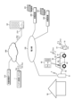
- FIG. 1 is an explanatory diagram of how a vehicle battery is managed by a battery management system.
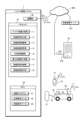
- FIG. 2 is a configuration diagram of the battery management system.
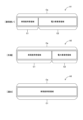
- FIG. 3 is an explanatory diagram of a mode in which the capacity of each area of the battery is changed.
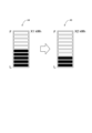
- FIG. 4 is a first display example of the amount of remaining electrical storage when the capacity of the first area allocated to the vehicle user is changed.
- FIG. 5 is a second display example of the remaining amount of stored electricity when the capacity of the first area allocated to the vehicle user is changed.
- FIG. 6 is a flowchart of a process for changing the capacity of the first area allocated to a vehicle user.
- the battery management system 1 of this embodiment manages the battery 62 of the vehicle 60.
- the battery management system 1 virtually divides the capacity Ca of the battery 62 mounted on the vehicle 60 into a first area C1 and a second area C2, and assigns the first area C1 to the vehicle-use area.
- the second area C2 is allocated to the electric power company U1, and the second area C2 is allocated to the electric power company U2.
- the battery management system 1 enables the vehicle user U1 to use the battery 62 in the first area C1 and the electric power company U2 to use the battery 62 in the second area C2.
- the vehicle 60 corresponds to a moving object according to the present disclosure
- the vehicle user U1 corresponds to a first user according to the present disclosure
- the electric power company U2 corresponds to a second user according to the present disclosure.
- the capacity of the battery 62 may be divided into three or more areas and allocated to three or more users.
- the vehicle 60 is an electric vehicle (an electric vehicle, a plug-in hybrid vehicle, etc.) that uses a battery 62 as a driving source, and is equipped with a charging/discharging equipment 51 and a charging/discharging cable 52 attached to a house 50 such as the home of the vehicle user U1. Connected by The battery 62 is charged with power supplied from the charging and discharging equipment 51 via the charging and discharging cable 52, and also supplies power to the charging and discharging equipment 51.
- the charging/discharging equipment 51 is connected via the power grid 100 to a plurality of power generation facilities 200 operated by the electric power company U2, and supplies generated power from the power generation facilities 200 to the power grid 100. Further, the battery 62 is charged with surplus generated power via the charging/discharging equipment 51, and when the generated power is insufficiently supplied to the power grid 100, the discharged power from the battery 62 is supplied to the power grid 100. Power generation equipment 200 uses solar panels 201 to generate power.
- the battery management system 1 communicates with a vehicle control device 61, a charging/discharging facility 51, a communication terminal 70 used by a vehicle user U1, a management system 210 of an electric power company U2, a weather information server 310, etc. via a communication network 300. Communicate between.
- the communication terminal 70 is a smartphone, a mobile phone, a tablet terminal, a notebook computer, a desktop computer, an in-vehicle communication device including a car navigation device, or the like.
- the battery management system 1 transmits to the vehicle control device 61 ratio instruction information Dvr that instructs setting of the ratio between the first region C1 and the second region C2 of the battery 62 (setting the capacity of each region).
- the vehicle control device 61 controls the capacity of the battery 62 for use by the vehicle user U1 in the first region C1 (discharging and regenerative charging associated with power consumption in the vehicle 60, and controlling the capacity of the battery 62 by the vehicle user U1) based on the ratio instruction information Dvr. (charging from the charging/discharging equipment 51 based on the operation of (discharge).
- the battery management system 1 also controls the battery 60 based on external factors such as a request from the vehicle user U1, a request from the electric power company U2, and the outside temperature in the vicinity of the vehicle 60 provided by the weather information server 310.
- a process of changing the capacity of the first area C1 and second area C2 is executed. For example, when receiving capacity change request information Ccr requesting an increase in the capacity of the first region C1 transmitted from the communication terminal 70 of the vehicle user U1, the battery management system 1 transmits the capacity change request information Ccr from the communication terminal 70 of the vehicle user U1 to the management system 210 of the electric power company U2. It is determined whether or not the acceptance conditions are satisfied based on the acceptance condition information Awc sent from the.
- the battery management system 1 changes the capacity of the first area C1 and the second area C2 in response to the request change request, and the rate at which the capacity change is instructed.
- the instruction information Dvr is transmitted to the vehicle control device 61.
- the vehicle control device 61 that has received the ratio instruction information Dvr causes the change in the capacity of the first area C1 and the second area C2 to be reflected in the charging/discharging control of the battery 62, and displays on the display unit 63 the capacity of the first area C1. Displays an indication that the amount has increased.
- FIG. 1 shows one vehicle user U1 and one electric power company U2 for convenience of explanation
- the battery management system 1 is designed to handle the divided usage of batteries installed in multiple vehicles. Similar adjustment processing will be performed for vehicle users and multiple electric power companies.
- battery management system 1 is a computer system including a processor 10, a memory 30, a communication unit 40, and the like.
- the communication unit 40 communicates with the vehicle control device 61, the communication terminal 70 used by the vehicle user U1, the management system 210 of the electric power company U2, the weather information server 310, etc. via the communication network 300. .
- the memory 30 stores the control program 31 of the battery management system 1, the division ratio data 32 indicating the setting of the division ratio between the first area C1 and the second area C2 of the battery 62 (the setting of the capacity of each area), and the information of the electric power company.
- Acceptance condition data 33 indicating acceptance conditions for changing the capacity of the second area C2 presented by U2 is stored.
- the processor 10 controls the battery capacity division section 11, the capacity change reception section 12, the capacity change adjustment section 13, the area capacity change section 14, the outside temperature recognition section 15, and the power consumption prediction section. 16, a capacity change application section 17, and a capacity change display section 18.
- the process executed by the battery capacity division unit 11 corresponds to the battery capacity division step in the battery management method of the present disclosure
- the process executed by the capacity change reception unit 12 corresponds to the capacity change reception step in the battery management method of the present disclosure.
- the process executed by the capacity change adjustment unit 13 corresponds to the capacity change adjustment step in the battery management method of the present disclosure
- the process executed by the area capacity change unit 14 corresponds to the area capacity change step in the battery management method of the present disclosure. corresponds to
- the battery capacity dividing unit 11 virtually divides the capacity Ca of the battery 62 mounted on the vehicle 60 into a first area C1 allocated to the vehicle user U1 and a second area C2 allocated to the electric power company U2. division ratio data 32 indicating the division ratio is stored in the memory 30. Further, the battery capacity dividing unit 11 transmits to the vehicle control device 61 division instruction information Dvr that instructs the use of the battery 62 divided into the first region C1 and the second region C2.
- the capacity change reception unit 12 receives capacity change request information Ccr transmitted from the communication terminal 70 used by the vehicle user U1, and accepts a request to change the capacity of the first area C1 from the vehicle user U1.
- the capacity change adjustment unit 13 receives the acceptance condition information Awc transmitted from the management system 210 of the electric power company U2, and recognizes the acceptance conditions for the capacity change in the second area C2 set by the electric power company U2.
- First acceptance condition A predetermined compensation corresponding to the decrease in capacity of the second region C2 is provided from the vehicle user U1 to the electric power company U2.
- Second acceptance condition The period during which the capacity of the second area C2 is reduced is limited to a predetermined period (such as several days) or less.
- the capacity change adjustment unit 13 stores acceptance condition data 33 indicating acceptance conditions in the memory 30.
- the capacity change receiving unit 12 receives a capacity change request for the first area C1
- the capacity change adjustment unit 13 determines whether or not the capacity of the second area C2 can be changed in response to the capacity change request. Specifically, when the capacity change request satisfies the first acceptance condition or the second acceptance condition, the capacity change adjustment unit 13 determines that it is possible to change the capacity of the second area C2 in response to the capacity change request. to decide.
- the capacity change adjustment unit 13 transmits the capacity change request information to the management system 210, and The electric power company U2 is inquired as to whether or not the capacity of the second area C2 can be changed. Then, when receiving capacity change permission information that permits a change in the capacity of the second area C2 in response to the capacity change request from the management system 210, the capacity change adjustment unit 13 It is determined that the capacity of C2 can be changed.
- the area capacity change unit 14 changes the capacity of the first area C1 and the second area C2 in response to the capacity change request. Change the capacity of area C2.
- the battery capacity division unit 11 updates the division ratio data 32 to data indicating the changed division ratio between the first region C1 and the second region C2, and the battery capacity division unit 11 updates the division ratio data 32 to data indicating the changed division ratio between the first region C1 and the second region C2, and divides the battery 62 according to the changed division ratio.
- the division instruction information Dvr instructing the use is transmitted to the vehicle control device 61.
- the outside temperature recognition unit 15 is based on weather information near the parking position of the vehicle 60 provided by the weather information server 310 or verification temperature information sent from the vehicle control device 61 by an outside temperature sensor installed in the vehicle 60. Then, the outside temperature near the vehicle 60 is recognized.
- the power consumption prediction unit 16 calculates equipment installed in the vehicle 60 (air conditioner, cooling device for temperature management of the battery 62, etc.) based on the outside temperature in the vicinity of the vehicle 60 recognized by the outside temperature recognition unit 15. Predict the power consumption of For example, the power consumption prediction unit 16 predicts that power consumption will increase due to heating by the air conditioner when the outside temperature is a low temperature below a predetermined temperature.
- the capacity change application unit 17 sends a request to the capacity change reception unit 12 according to the amount of change in power consumption.
- a capacity change request requesting a change in the capacity of the first area C1 is applied.
- the amount of fluctuation in power consumption is the amount of fluctuation over a certain period of time, such as on a daily or several day basis, and an application for capacity change may be made, for example, during several months of winter when power consumption is high.
- the content may be such that the first area C1 is requested to be increased in a certain period.
- the capacity of the first area C1 is increased from the normal setting of A1 during a period when the power consumption of the equipment of the vehicle 60 increases in winter and the power generation amount of the solar panel 201 decreases.
- A3 also transmits capacity change request information Ccr for increasing the capacity of the first region C1 from the communication terminal 70 to the battery management system 1 when the vehicle user U1 goes out in the vehicle 60, and in response This shows an example in which the capacity of the first region C1 increases to the total capacity Ca of the battery 62.
- the capacity change display unit 18 transmits display change information that instructs the area capacity change unit 14 to display that the area of the first area C1 has been changed to the vehicle control device 61.
- the vehicle control device 61 receives the display change information, it displays on the display unit 63 provided in the vehicle 60, indicating that the capacity of the first region C1 has been changed.
- FIG. 4 and 5 show display examples when the first area C1 is changed.
- FIG. 4 is a display example of displaying the capacity of the first area C1, in which the capacity is switched from X1 kWh indicated by A4 to X2 kWh indicated by A5.
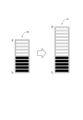
- FIG. 5 is a display example in which the size of the display area is changed, and when the capacity of the first area C1 increases, the size of the display area for the remaining amount of stored power changes from the size shown in A6 to the size shown in A7. has been enlarged in size.
- the capacity change receiving unit 12 determines the amount of power consumption when receiving the capacity change request information Ccr from the communication terminal 70 of the vehicle user U1 in step S1, or When the amount of variation in power consumption predicted by the prediction unit 16 exceeds a predetermined value and an application for capacity change is made, the process advances to step S2.
- step S2 the capacity change adjustment unit 13 determines whether the capacity change request information Ccr or the content of the capacity change request based on the capacity change application satisfies the first acceptance condition or the second acceptance condition presented by the electric power company U2. Decide whether or not. Then, when the content of the capacity change request satisfies the first acceptance condition or the second acceptance condition, the capacity change adjustment unit 13 advances the process to step S20, and if the content of the capacity change request meets the first acceptance condition or the second acceptance condition, the process proceeds to step S20. If the second acceptance condition is not satisfied, the process advances to step S3.
- step S3 the capacity change adjustment unit 13 transmits the capacity change request information Ccr to the management system 210 of the electric power company U2, and inquires whether the capacity of the second area C2 can be changed in accordance with the capacity change request.
- step S4 when the capacity change adjustment unit 13 receives capacity change acceptance information from the management system 210 of the electric power company U2 that approves a change in the capacity of the second area C2 in response to the capacity change request, the capacity change adjustment unit 13 performs step S4. The process advances to S20.
- the capacity change adjustment unit 13 advances the process to step S5, and informs the communication terminal 70 of the vehicle user U1 that the change in the first area C1 according to the capacity change request is not received. Sends information that capacity cannot be changed to notify that it is not possible. As a result, a notification that the capacity of the first area C1 cannot be changed is displayed on the display unit of the communication terminal 70.
- step S20 the area capacity changing unit 14 changes the capacity of the first area C1 and the second area C2 based on the capacity change request.
- step S21 the battery capacity dividing unit 11 transmits the division instruction information Dvr that instructs the division ratio corresponding to the capacity of the first region C1 and the second region C2 changed by the region capacity changing unit 14 to the vehicle control device 61. Send to. As a result, the control of the battery 62 by the vehicle control device 61 is changed to be based on the changed division ratio.
- the capacity change display unit 18 transmits display change information to the vehicle control device 61 instructing to change the display of the remaining amount of stored electricity according to the change in the capacity of the first region C1.
- the vehicle control device 61 that has received the display change information changes the display mode of the remaining power storage amount in the first area C1, as described above with reference to FIGS. 4 and 5.
- the capacity change display section 18 transmits capacity change implementation information that notifies the communication terminal 70 of the vehicle user U1 that the capacity of the first area C1 has been changed.
- the communication terminal 70 that has received the capacity change implementation information displays on the display unit of the communication terminal 70 notifying that the capacity of the first area C1 has been changed. Thereby, it is possible to notify the vehicle user U1 that the capacity of the first area C1 has been changed.
- the vehicle 60 is shown as the moving object of the present disclosure, but the moving object of the present disclosure may be any object that is equipped with a battery that is charged and discharged by a charging/discharging facility, and may be an aircraft, a ship, etc. It's okay.
- a request from one user who shares the battery 62 is required. It may be configured to inquire of other users whether the capacity change request is acceptable or not, and to obtain a response from the other users to the effect that the capacity change is permitted. This makes it possible to adjust the capacity change flexibly and reliably.
- the outside temperature recognition section 15, the power consumption prediction section 16, and the capacity change application section 17 are provided, and the capacity of the first area C1 is calculated based on the power consumption of the equipment installed in the vehicle 60.
- the configuration may be such that the outside temperature recognition unit 15, the power consumption prediction unit 16, and the capacity change application unit 17 are omitted.
- the capacity change display unit 18 is provided, and when the capacity of the first area C1 is changed, the capacity of the first area C1 is changed by the display unit 63 of the vehicle 60 or the display unit of the communication terminal 70. Although the capacity change display unit 18 is displayed, the configuration may be such that the capacity change display unit 18 is omitted.
- the battery management system 1 of the present disclosure is configured by a computer system that communicates with the vehicle 60 in which the battery 62 is mounted.
- the battery management system may be configured as a function of the vehicle control device 61.
- the vehicle control device 61 is configured to communicate with the communication terminal 70 of the vehicle user U1 and the management system 210 of the electric power company U2.
- FIG. 2 is a schematic diagram showing the functional configuration of the battery management system 1 divided into main processing contents. It may be structured by the following classifications. Furthermore, the processing of each component may be executed by one hardware unit or by multiple hardware units. Moreover, the processing by each component shown in FIG. 6 may be executed by one program, or may be executed by a plurality of programs.
- the capacity of the battery is virtually divided into a predetermined number of areas, and each of the areas is individually allocated to the predetermined number of users.
- a battery capacity dividing section that allows a first user to use the battery within the range of the area allocated to each user; a capacity change reception unit that receives a capacity change request requesting a change in the capacity of the first area that is the allocated area; and a capacity change reception unit that, when the capacity change request is accepted, a capacity change adjustment unit that determines whether or not the capacity can be changed in response to the capacity change request with respect to the second area that is the area allocated to a second user other than the first user among the users; , when the capacity change adjustment unit determines that the capacity of the second area can be changed in response to the capacity change request, the first area and the second area are adjusted in response to the capacity change request.
- a battery management system comprising: an area capacity changing unit that changes the capacity of the battery.
- the capacity change adjustment unit determines whether or not the capacity of the first area allocated to the first user can be changed, and the area capacity change unit changes the capacity of the first area. By doing so, it is possible to support more effective utilization of the battery installed in the mobile object.
- the capacity change adjustment unit is configured to adjust the capacity change adjustment unit in response to the capacity change request when the capacity change request satisfies a preset condition for accepting a capacity change of the second area by the second user.
- the battery management system of Configuration 2 by setting in advance the acceptance conditions for changing the capacity of the second area, it is possible to quickly change the capacity of the battery area in response to a capacity change request.
- (Configuration 4) Battery management according to Configuration 2 or 3, wherein the acceptance condition is that the content of the capacity change request is a change in the capacity of the first area limited to a predetermined period or less. system.
- the battery management system of Configuration 4 when the capacity change of the first area due to a capacity change request is for a short period of time, the first area and the first area are immediately changed without performing the process of obtaining consent from the second user. The capacity of the two areas can be changed.
- (Configuration 5) An outside temperature recognition unit that recognizes the outside temperature in the vicinity of the mobile body, and a power consumption of equipment mounted on the mobile body based on the outside temperature recognized by the outside temperature recognition unit. Applying the capacity change request to the capacity change reception unit when the amount of variation in the power consumption predicted by the power consumption prediction unit and the power consumption prediction unit is equal to or greater than a predetermined value.
- the battery management system according to any one of configurations 1 to 4, comprising: a capacity change application unit for applying a capacity change; According to the battery management system of configuration 5, the power consumption of devices (air conditioners, battery cooling and heating devices, etc.) whose power consumption is expected to change according to changes in the outside temperature near the mobile object is set to a predetermined value. When the value exceeds the value, the capacities of the first area and the second area can be efficiently changed without waiting for the first user to apply for a request to change the capacity of the first area.
- the first user is a user of the mobile body, and when the capacity of the first area is changed by the area capacity changing unit, the first user is a user of the mobile body, and when the capacity of the first area is changed by the area capacity changing unit, a A configuration including a capacity change display unit that displays that the capacity of the first area has been changed by a first display unit that displays a charging state or a second display unit of a communication terminal used by the first user.
- the battery management system according to any one of configurations 1 to 5. According to the battery management system of configuration 6, the fact that the capacity of the first area has been changed is displayed to the first user by the first display section provided in the mobile object or the second display section of the communication terminal. Can be notified.
- (Configuration 7) A battery management method executed by a computer, in which, for a battery mounted on a mobile object, the capacity of the battery is virtually divided into a predetermined number of areas, and the areas are used for the predetermined number of areas. a step of dividing the battery capacity by individually allocating the battery to each user, thereby allowing the use of the battery by each user within the range of the area allocated to each user; a capacity change accepting step for accepting a capacity change request for requesting a change in the capacity of the first area, which is the area allocated to a first user, which is any user; and the capacity change accepting step, the capacity change is When the request is accepted, the second area, which is the area allocated to a second user other than the first user among the predetermined number of users, responds to the capacity change request.
- a battery management method comprising: changing the capacity of the first area and the second area accordingly.
- SYMBOLS 1 Battery management system, 10... Processor, 11... Battery capacity division part, 12... Capacity change reception part, 13... Capacity change adjustment part, 14... Area capacity change part, 15... Outside temperature recognition part, 16... Power consumption Prediction unit, 17... Capacity change application unit, 18... Capacity change display unit, 30... Memory, 31... Control program, 32... Division ratio data, 33... Acceptance condition data, 40... Communication unit, 50... House, 51...
- Charge Discharge equipment 52...Charging/discharging cable, 60...Vehicle (mobile object), 61...Vehicle control device, 62...Battery, 63...Vehicle display section, 70...Communication terminal, 100...Power network, 200...Power generation equipment, 201...Solar Panel, 210... Management system of electric power company, 300... Communication network, 310... Weather information server, U1... Vehicle user (first user), U2... Electric power company (second user), C1... First Area, C2...second area.
Landscapes
- Engineering & Computer Science (AREA)
- Business, Economics & Management (AREA)
- Power Engineering (AREA)
- Economics (AREA)
- Human Resources & Organizations (AREA)
- Strategic Management (AREA)
- Tourism & Hospitality (AREA)
- Theoretical Computer Science (AREA)
- General Physics & Mathematics (AREA)
- General Business, Economics & Management (AREA)
- Marketing (AREA)
- Physics & Mathematics (AREA)
- Entrepreneurship & Innovation (AREA)
- Health & Medical Sciences (AREA)
- Operations Research (AREA)
- General Health & Medical Sciences (AREA)
- Mechanical Engineering (AREA)
- Primary Health Care (AREA)
- Quality & Reliability (AREA)
- Development Economics (AREA)
- Game Theory and Decision Science (AREA)
- Transportation (AREA)
- Public Health (AREA)
- Water Supply & Treatment (AREA)
- Educational Administration (AREA)
- Life Sciences & Earth Sciences (AREA)
- Sustainable Development (AREA)
- Sustainable Energy (AREA)
- Charge And Discharge Circuits For Batteries Or The Like (AREA)
- Secondary Cells (AREA)
Abstract
Description
本発明はかかる背景に鑑みてなされたものであり、移動体に搭載されたバッテリのより有効な活用をサポートすることができるバッテリ管理システム、及びバッテリ管理方法を提供することを目的とする。
図1を参照して、本実施形態のバッテリ管理システム1による車両60のバッテリ62の管理態様について説明する。バッテリ管理システム1は、吹き出し65により示したように、車両60に搭載されたバッテリ62の容量Caを、第1領域C1と第2領域C2に仮想的に分割し、第1領域C1を車両使用者U1に割り当て、第2領域C2を電力事業者U2に割り当てる。
図2から図5を参照して、バッテリ管理システムの構成について説明する。図2を参照して、バッテリ管理システム1は、プロセッサ10、メモリ30、通信部40等を備えるコンピュータシステムである。通信部40は、通信ネットワーク300を介して、車両制御装置61、車両使用者U1により使用される通信端末70、電力事業者U2の管理システム210、気象情報サーバー310等との間で通信を行う。
第1容認条件…第2領域C2の容量の減少分に応じた所定対価が、車両使用者U1から電力事業者U2に提供される。
第2容認条件…第2領域C2の容量が減少される期間が、所定期間(数日等)以下に限定される。
図6に示したフローチャートに従って、図1,2に示した状況で、バッテリ管理システム1により実行される第1領域C1の容量変更の手順について説明する。
上記実施形態では、本開示の移動体として車両60を示したが、本開示の移動体は、充放電設備により充放電されるバッテリを備えたものであればよく、飛行体、船舶等であってもよい。
上記実施形態は、以下の構成の具体例である。
構成1のバッテリ管理システムによれば、第1使用者に割り当てられた第1領域の容量の変更の可否を、容量変更調整部により判断して、領域容量変更部により第1領域の容量を変更することにより、移動体に搭載されたバッテリのより有効な活用をサポートすることができる。
構成2のバッテリ管理システムによれば、第2領域の容量変更の容認条件を予め設定することにより、容量変更要求に応じたバッテリの領域の容量の変更を、速やかに行うことができる。
構成3のバッテリ管理システムによれば、第2使用者に対する所定対価の提供により、容量変更要求に応じた第1領域の容量の増加及び第2領域の容量の減少を、速やかに行うことができる。
構成4のバッテリ管理システムによれば、容量変更要求による第1領域の容量の変更が短期間である場合に、第2使用者に対する了解を得る処理を行うことなく、速やかに第1領域及び第2領域の容量を変更することができる。
構成5のバッテリ管理システムによれば、移動体の付近の外気温の変化に応じて消費電力が変化すると想定される機器(空調装置、バッテリの冷却及び加温装置等)の電力消費量が所定値以上となった場合に、第1使用者による第1領域の容量変更の要求の申請を待つことなく、第1領域及び第2領域の容量を効率良く変更することができる。
構成6のバッテリ管理システムによれば、第1領域の容量が変更されたことを、移動体に備えられた第1表示部、又は通信端末の第2表示部による表示によって、第1使用者に通知することができる。
構成7のバッテリ管理方法をコンピュータにより実行することによって、構成1のバッテリ管理システムと同様の作用効果を得ることができる。
Claims (7)
- 移動体に搭載されたバッテリについて、前記バッテリの容量を所定数の領域に仮想的に分割して、前記領域を前記所定数の使用者に対して個別に割り当てることにより、各使用者による各使用者に割り当てられた前記領域の範囲での前記バッテリの使用を可能にするバッテリ容量分割部と、
前記所定数の使用者のうちのいずれかの使用者である第1使用者に割り当てられた前記領域である第1領域の容量の変更を要求する容量変更要求を受け付ける容量変更受付部と、
前記容量変更受付部により、前記容量変更要求が受け付けられたときに、前記所定数の使用者のうちの前記第1使用者以外の第2使用者に対して割り当てられた前記領域である第2領域について、前記容量変更要求に応じた容量変更の可否を判断する容量変更調整部と、
前記容量変更調整部により、前記容量変更要求に応じた前記第2領域の容量変更が可能であると判断された場合に、前記容量変更要求に応じて、前記第1領域及び前記第2領域の容量を変更する領域容量変更部と、
を備えるバッテリ管理システム。 - 前記容量変更調整部は、予め設定された前記第2使用者による前記第2領域の容量変更の容認条件を、前記容量変更要求が満たす場合に、前記容量変更要求に応じた前記第2領域の容量変更が可能であると判断する
請求項1に記載のバッテリ管理システム。 - 前記容認条件として、前記容量変更要求による要求内容が前記第1領域の容量の増加である場合に、前記容量変更要求に応じた前記第2領域の容量の減少に対する所定対価を、前記第1使用者が前記第2使用者に提供すること、が設定されている
請求項2に記載のバッテリ管理システム。 - 前記容認条件として、前記容量変更要求の内容が、所定期間以下に限定した前記第1領域の容量の変更であること、が設定されている
請求項2又は請求項3に記載のバッテリ管理システム。 - 前記移動体の付近の外気温を認識する外気温認識部と、
前記外気温認識部により認識される前記外気温に基づいて、前記移動体に搭載された機器の電力消費量を予測する電力消費量予測部と、
前記電力消費量予測部により予測される前記電力消費量の変動量が所定値以上となった場合に、前記容量変更受付部に対して前記容量変更要求を申請する容量変更申請部と、
を備える
請求項1から請求項4のうちいずれか1項に記載のバッテリ管理システム。 - 前記第1使用者は前記移動体の使用者であり、
前記領域容量変更部により前記第1領域の容量が変更されたときに、前記移動体に備えられて前記第1領域の充電状態を表示する第1表示部、又は前記第1使用者により使用される通信端末の第2表示部により、前記第1領域の容量が変更されたことを表示する容量変更表示部を備える
請求項1から請求項5のうちいずれか1項に記載のバッテリ管理システム。 - コンピュータにより実行されるバッテリ管理方法であって、
移動体に搭載されたバッテリについて、前記バッテリの容量を所定数の領域に仮想的に分割して、前記領域を前記所定数の使用者に対して個別に割り当てることにより、各使用者による各使用者に割り当てられた前記領域の範囲での前記バッテリの使用を可能にするバッテリ容量分割ステップと、
前記所定数の使用者のうちのいずれかの使用者である第1使用者に割り当てられた前記領域である第1領域の容量の変更を要求する容量変更要求を受け付ける容量変更受付ステップと、
前記容量変更受付ステップにより、前記容量変更要求が受け付けられたときに、前記所定数の使用者のうちの前記第1使用者以外の第2使用者に対して割り当てられた前記領域である第2領域について、前記容量変更要求に応じた容量変更の可否を判断する容量変更調整ステップと、
前記容量変更調整ステップにより、前記容量変更要求に応じた前記第2領域の容量変更が可能であると判断された場合に、前記容量変更要求に応じて、前記第1領域及び前記第2領域の容量を変更する領域容量変更ステップと、
を含むバッテリ管理方法。
Priority Applications (4)
| Application Number | Priority Date | Filing Date | Title |
|---|---|---|---|
| PCT/JP2022/010926 WO2023170931A1 (ja) | 2022-03-11 | 2022-03-11 | バッテリ管理システム、及びバッテリ管理方法 |
| EP22930912.5A EP4492628A4 (en) | 2022-03-11 | 2022-03-11 | BATTERY MANAGEMENT SYSTEM AND BATTERY MANAGEMENT PROCEDURES |
| US18/844,598 US20250233436A1 (en) | 2022-03-11 | 2022-03-11 | Battery management system, and battery management method |
| JP2024505814A JP7671916B2 (ja) | 2022-03-11 | 2022-03-11 | バッテリ管理システム、及びバッテリ管理方法 |
Applications Claiming Priority (1)
| Application Number | Priority Date | Filing Date | Title |
|---|---|---|---|
| PCT/JP2022/010926 WO2023170931A1 (ja) | 2022-03-11 | 2022-03-11 | バッテリ管理システム、及びバッテリ管理方法 |
Publications (1)
| Publication Number | Publication Date |
|---|---|
| WO2023170931A1 true WO2023170931A1 (ja) | 2023-09-14 |
Family
ID=87936471
Family Applications (1)
| Application Number | Title | Priority Date | Filing Date |
|---|---|---|---|
| PCT/JP2022/010926 Ceased WO2023170931A1 (ja) | 2022-03-11 | 2022-03-11 | バッテリ管理システム、及びバッテリ管理方法 |
Country Status (4)
| Country | Link |
|---|---|
| US (1) | US20250233436A1 (ja) |
| EP (1) | EP4492628A4 (ja) |
| JP (1) | JP7671916B2 (ja) |
| WO (1) | WO2023170931A1 (ja) |
Cited By (1)
| Publication number | Priority date | Publication date | Assignee | Title |
|---|---|---|---|---|
| WO2025126490A1 (ja) * | 2023-12-15 | 2025-06-19 | 日本電信電話株式会社 | リソース配分システム、リソース配分方法、及びプログラム |
Citations (5)
| Publication number | Priority date | Publication date | Assignee | Title |
|---|---|---|---|---|
| JP2008141926A (ja) * | 2006-12-05 | 2008-06-19 | Hitachi Ltd | 家庭用電力蓄積装置、車載用電力蓄積装置、電力供給・蓄積システム及び蓄電制御方法 |
| WO2017170741A1 (ja) * | 2016-03-29 | 2017-10-05 | 京セラ株式会社 | 電力管理装置、電力管理システム及び電力管理方法 |
| JP2019161939A (ja) * | 2018-03-15 | 2019-09-19 | シャープ株式会社 | 電力制御装置および電力制御方法 |
| WO2020148850A1 (ja) | 2019-01-17 | 2020-07-23 | 本田技研工業株式会社 | 容量制御装置及びプログラム |
| JP2021036762A (ja) * | 2017-03-28 | 2021-03-04 | 京セラ株式会社 | 蓄電装置 |
Family Cites Families (2)
| Publication number | Priority date | Publication date | Assignee | Title |
|---|---|---|---|---|
| CN107662618A (zh) * | 2016-07-29 | 2018-02-06 | 福特环球技术公司 | 管理填充共享车辆中的能量源的系统和方法 |
| US11167659B2 (en) * | 2019-02-05 | 2021-11-09 | Inventus Holdings, LLC. | Allocation of electrical energy within a storage cell |
-
2022
- 2022-03-11 WO PCT/JP2022/010926 patent/WO2023170931A1/ja not_active Ceased
- 2022-03-11 US US18/844,598 patent/US20250233436A1/en active Pending
- 2022-03-11 JP JP2024505814A patent/JP7671916B2/ja active Active
- 2022-03-11 EP EP22930912.5A patent/EP4492628A4/en active Pending
Patent Citations (5)
| Publication number | Priority date | Publication date | Assignee | Title |
|---|---|---|---|---|
| JP2008141926A (ja) * | 2006-12-05 | 2008-06-19 | Hitachi Ltd | 家庭用電力蓄積装置、車載用電力蓄積装置、電力供給・蓄積システム及び蓄電制御方法 |
| WO2017170741A1 (ja) * | 2016-03-29 | 2017-10-05 | 京セラ株式会社 | 電力管理装置、電力管理システム及び電力管理方法 |
| JP2021036762A (ja) * | 2017-03-28 | 2021-03-04 | 京セラ株式会社 | 蓄電装置 |
| JP2019161939A (ja) * | 2018-03-15 | 2019-09-19 | シャープ株式会社 | 電力制御装置および電力制御方法 |
| WO2020148850A1 (ja) | 2019-01-17 | 2020-07-23 | 本田技研工業株式会社 | 容量制御装置及びプログラム |
Non-Patent Citations (1)
| Title |
|---|
| See also references of EP4492628A4 |
Cited By (1)
| Publication number | Priority date | Publication date | Assignee | Title |
|---|---|---|---|---|
| WO2025126490A1 (ja) * | 2023-12-15 | 2025-06-19 | 日本電信電話株式会社 | リソース配分システム、リソース配分方法、及びプログラム |
Also Published As
| Publication number | Publication date |
|---|---|
| US20250233436A1 (en) | 2025-07-17 |
| EP4492628A4 (en) | 2025-04-23 |
| EP4492628A1 (en) | 2025-01-15 |
| JPWO2023170931A1 (ja) | 2023-09-14 |
| JP7671916B2 (ja) | 2025-05-02 |
Similar Documents
| Publication | Publication Date | Title |
|---|---|---|
| US12288173B2 (en) | Vehicle allocation management method and vehicle allocation management device | |
| JP7230704B2 (ja) | エネルギマネージメント方法、及びエネルギマネージメント装置 | |
| US20210382501A1 (en) | Centrally dispatched power supply using autonomous electric vehicle fleet | |
| US20160250942A1 (en) | Charging state management method, charging state management device, and program | |
| CN112026584B (zh) | 一种电动汽车能量分配方法、装置、车辆及介质 | |
| US20200403419A1 (en) | Power management system, power management method, and storage medium | |
| EP3016238A1 (en) | Charging state management method, charging state management device, and program | |
| EP3016237A1 (en) | Method for controlling charging power, system for controlling charging power, and program | |
| JP2021158731A (ja) | エネルギー供給システム、エネルギー供給方法 | |
| KR20220068860A (ko) | Ems와 연동되는 전기자동차 충전기 제어 시스템 | |
| JP2016046934A (ja) | 電力管理システム、地域電力管理装置、需要家電力管理装置 | |
| JP2020202623A (ja) | 電力管理システム | |
| JP7671916B2 (ja) | バッテリ管理システム、及びバッテリ管理方法 | |
| JP2021151017A (ja) | 電力管理装置および電力管理方法 | |
| JP7439154B2 (ja) | バッテリ管理システム、及びバッテリ管理方法 | |
| US12248959B2 (en) | Battery replacement control device and battery replacement control system | |
| CN119218041A (zh) | 一种基于峰谷电价的动态充电分配方法、装置及充电桩 | |
| JP6625181B2 (ja) | 管理装置、及び、制御方法 | |
| US12533987B2 (en) | Electric vehicle management device and electric vehicle management system | |
| JP7693594B2 (ja) | 電力取引システム及びプログラム | |
| EP4328079B1 (en) | Server, system, and method to reduce display of advertisements | |
| JP7628656B2 (ja) | バッテリ管理システム、及びバッテリ管理方法 | |
| CN119611003B (zh) | 基于功率分配的车辆控制方法、装置、设备及存储介质 | |
| CN119200699B (zh) | 飞行器在途控制方法、存储介质及计算机程序产品 | |
| KR20230119883A (ko) | Ess의 전력 운용 방법 및 이를 지원하는 전력 관리 장치 |
Legal Events
| Date | Code | Title | Description |
|---|---|---|---|
| 121 | Ep: the epo has been informed by wipo that ep was designated in this application |
Ref document number: 22930912 Country of ref document: EP Kind code of ref document: A1 |
|
| ENP | Entry into the national phase |
Ref document number: 2024505814 Country of ref document: JP Kind code of ref document: A |
|
| WWE | Wipo information: entry into national phase |
Ref document number: 18844598 Country of ref document: US |
|
| WWE | Wipo information: entry into national phase |
Ref document number: 2022930912 Country of ref document: EP |
|
| NENP | Non-entry into the national phase |
Ref country code: DE |
|
| ENP | Entry into the national phase |
Ref document number: 2022930912 Country of ref document: EP Effective date: 20241011 |
|
| WWP | Wipo information: published in national office |
Ref document number: 18844598 Country of ref document: US |