WO2023170983A1 - 輸送機器 - Google Patents
輸送機器 Download PDFInfo
- Publication number
- WO2023170983A1 WO2023170983A1 PCT/JP2022/012280 JP2022012280W WO2023170983A1 WO 2023170983 A1 WO2023170983 A1 WO 2023170983A1 JP 2022012280 W JP2022012280 W JP 2022012280W WO 2023170983 A1 WO2023170983 A1 WO 2023170983A1
- Authority
- WO
- WIPO (PCT)
- Prior art keywords
- hydrogen
- nitrogen
- ammonia
- tank
- supplied
- Prior art date
- Legal status (The legal status is an assumption and is not a legal conclusion. Google has not performed a legal analysis and makes no representation as to the accuracy of the status listed.)
- Ceased
Links
Images



Classifications
-
- B—PERFORMING OPERATIONS; TRANSPORTING
- B63—SHIPS OR OTHER WATERBORNE VESSELS; RELATED EQUIPMENT
- B63H—MARINE PROPULSION OR STEERING
- B63H21/00—Use of propulsion power plant or units on vessels
- B63H21/38—Apparatus or methods specially adapted for use on marine vessels, for handling power plant or unit liquids, e.g. lubricants, coolants, fuels or the like
-
- B—PERFORMING OPERATIONS; TRANSPORTING
- B60—VEHICLES IN GENERAL
- B60L—PROPULSION OF ELECTRICALLY-PROPELLED VEHICLES; SUPPLYING ELECTRIC POWER FOR AUXILIARY EQUIPMENT OF ELECTRICALLY-PROPELLED VEHICLES; ELECTRODYNAMIC BRAKE SYSTEMS FOR VEHICLES IN GENERAL; MAGNETIC SUSPENSION OR LEVITATION FOR VEHICLES; MONITORING OPERATING VARIABLES OF ELECTRICALLY-PROPELLED VEHICLES; ELECTRIC SAFETY DEVICES FOR ELECTRICALLY-PROPELLED VEHICLES
- B60L50/00—Electric propulsion with power supplied within the vehicle
- B60L50/50—Electric propulsion with power supplied within the vehicle using propulsion power supplied by batteries or fuel cells
- B60L50/70—Electric propulsion with power supplied within the vehicle using propulsion power supplied by batteries or fuel cells using power supplied by fuel cells
-
- B—PERFORMING OPERATIONS; TRANSPORTING
- B60—VEHICLES IN GENERAL
- B60L—PROPULSION OF ELECTRICALLY-PROPELLED VEHICLES; SUPPLYING ELECTRIC POWER FOR AUXILIARY EQUIPMENT OF ELECTRICALLY-PROPELLED VEHICLES; ELECTRODYNAMIC BRAKE SYSTEMS FOR VEHICLES IN GENERAL; MAGNETIC SUSPENSION OR LEVITATION FOR VEHICLES; MONITORING OPERATING VARIABLES OF ELECTRICALLY-PROPELLED VEHICLES; ELECTRIC SAFETY DEVICES FOR ELECTRICALLY-PROPELLED VEHICLES
- B60L50/00—Electric propulsion with power supplied within the vehicle
- B60L50/90—Electric propulsion with power supplied within the vehicle using propulsion power supplied by specific means not covered by groups B60L50/10 - B60L50/50, e.g. by direct conversion of thermal nuclear energy into electricity
-
- B—PERFORMING OPERATIONS; TRANSPORTING
- B63—SHIPS OR OTHER WATERBORNE VESSELS; RELATED EQUIPMENT
- B63B—SHIPS OR OTHER WATERBORNE VESSELS; EQUIPMENT FOR SHIPPING
- B63B25/00—Load-accommodating arrangements, e.g. stowing, trimming; Vessels characterised thereby
- B63B25/02—Load-accommodating arrangements, e.g. stowing, trimming; Vessels characterised thereby for bulk goods
- B63B25/08—Load-accommodating arrangements, e.g. stowing, trimming; Vessels characterised thereby for bulk goods fluid
-
- B—PERFORMING OPERATIONS; TRANSPORTING
- B63—SHIPS OR OTHER WATERBORNE VESSELS; RELATED EQUIPMENT
- B63H—MARINE PROPULSION OR STEERING
- B63H21/00—Use of propulsion power plant or units on vessels
- B63H21/12—Use of propulsion power plant or units on vessels the vessels being motor-driven
- B63H21/14—Use of propulsion power plant or units on vessels the vessels being motor-driven relating to internal-combustion engines
-
- B—PERFORMING OPERATIONS; TRANSPORTING
- B63—SHIPS OR OTHER WATERBORNE VESSELS; RELATED EQUIPMENT
- B63H—MARINE PROPULSION OR STEERING
- B63H21/00—Use of propulsion power plant or units on vessels
- B63H21/12—Use of propulsion power plant or units on vessels the vessels being motor-driven
- B63H21/17—Use of propulsion power plant or units on vessels the vessels being motor-driven by electric motor
-
- B—PERFORMING OPERATIONS; TRANSPORTING
- B63—SHIPS OR OTHER WATERBORNE VESSELS; RELATED EQUIPMENT
- B63J—AUXILIARIES ON VESSELS
- B63J3/00—Driving of auxiliaries
- B63J3/02—Driving of auxiliaries from propulsion power plant
-
- C—CHEMISTRY; METALLURGY
- C01—INORGANIC CHEMISTRY
- C01B—NON-METALLIC ELEMENTS; COMPOUNDS THEREOF; METALLOIDS OR COMPOUNDS THEREOF NOT COVERED BY SUBCLASS C01C
- C01B3/00—Hydrogen; Gaseous mixtures containing hydrogen; Separation of hydrogen from mixtures containing it; Purification of hydrogen; Reversible storage of hydrogen
- C01B3/02—Production of hydrogen; Production of gaseous mixtures containing hydrogen
- C01B3/04—Production of hydrogen; Production of gaseous mixtures containing hydrogen by decomposition of inorganic compounds
- C01B3/047—Decomposition of ammonia
-
- F—MECHANICAL ENGINEERING; LIGHTING; HEATING; WEAPONS; BLASTING
- F02—COMBUSTION ENGINES; HOT-GAS OR COMBUSTION-PRODUCT ENGINE PLANTS
- F02M—SUPPLYING COMBUSTION ENGINES IN GENERAL WITH COMBUSTIBLE MIXTURES OR CONSTITUENTS THEREOF
- F02M21/00—Apparatus for supplying engines with non-liquid fuels, e.g. gaseous fuels stored in liquid form
- F02M21/02—Apparatus for supplying engines with non-liquid fuels, e.g. gaseous fuels stored in liquid form for gaseous fuels
- F02M21/0203—Apparatus for supplying engines with non-liquid fuels, e.g. gaseous fuels stored in liquid form for gaseous fuels characterised by the type of gaseous fuel
- F02M21/0206—Non-hydrocarbon fuels, e.g. hydrogen, ammonia or carbon monoxide
-
- F—MECHANICAL ENGINEERING; LIGHTING; HEATING; WEAPONS; BLASTING
- F02—COMBUSTION ENGINES; HOT-GAS OR COMBUSTION-PRODUCT ENGINE PLANTS
- F02M—SUPPLYING COMBUSTION ENGINES IN GENERAL WITH COMBUSTIBLE MIXTURES OR CONSTITUENTS THEREOF
- F02M21/00—Apparatus for supplying engines with non-liquid fuels, e.g. gaseous fuels stored in liquid form
- F02M21/02—Apparatus for supplying engines with non-liquid fuels, e.g. gaseous fuels stored in liquid form for gaseous fuels
- F02M21/0218—Details on the gaseous fuel supply system, e.g. tanks, valves, pipes, pumps, rails, injectors or mixers
- F02M21/0227—Means to treat or clean gaseous fuels or fuel systems, e.g. removal of tar, cracking, reforming or enriching
-
- H—ELECTRICITY
- H01—ELECTRIC ELEMENTS
- H01M—PROCESSES OR MEANS, e.g. BATTERIES, FOR THE DIRECT CONVERSION OF CHEMICAL ENERGY INTO ELECTRICAL ENERGY
- H01M8/00—Fuel cells; Manufacture thereof
- H01M8/04—Auxiliary arrangements, e.g. for control of pressure or for circulation of fluids
- H01M8/04223—Auxiliary arrangements, e.g. for control of pressure or for circulation of fluids during start-up or shut-down; Depolarisation or activation, e.g. purging; Means for short-circuiting defective fuel cells
- H01M8/04231—Purging of the reactants
-
- B—PERFORMING OPERATIONS; TRANSPORTING
- B63—SHIPS OR OTHER WATERBORNE VESSELS; RELATED EQUIPMENT
- B63B—SHIPS OR OTHER WATERBORNE VESSELS; EQUIPMENT FOR SHIPPING
- B63B17/00—Vessels parts, details, or accessories, not otherwise provided for
- B63B17/0027—Tanks for fuel or the like ; Accessories therefor, e.g. tank filler caps
-
- B—PERFORMING OPERATIONS; TRANSPORTING
- B63—SHIPS OR OTHER WATERBORNE VESSELS; RELATED EQUIPMENT
- B63H—MARINE PROPULSION OR STEERING
- B63H21/00—Use of propulsion power plant or units on vessels
- B63H2021/003—Use of propulsion power plant or units on vessels the power plant using fuel cells for energy supply or accumulation, e.g. for buffering photovoltaic energy
-
- B—PERFORMING OPERATIONS; TRANSPORTING
- B63—SHIPS OR OTHER WATERBORNE VESSELS; RELATED EQUIPMENT
- B63J—AUXILIARIES ON VESSELS
- B63J3/00—Driving of auxiliaries
-
- C—CHEMISTRY; METALLURGY
- C01—INORGANIC CHEMISTRY
- C01B—NON-METALLIC ELEMENTS; COMPOUNDS THEREOF; METALLOIDS OR COMPOUNDS THEREOF NOT COVERED BY SUBCLASS C01C
- C01B2203/00—Integrated processes for the production of hydrogen or synthesis gas
- C01B2203/02—Processes for making hydrogen or synthesis gas
- C01B2203/0266—Processes for making hydrogen or synthesis gas containing a decomposition step
- C01B2203/0277—Processes for making hydrogen or synthesis gas containing a decomposition step containing a catalytic decomposition step
-
- C—CHEMISTRY; METALLURGY
- C01—INORGANIC CHEMISTRY
- C01B—NON-METALLIC ELEMENTS; COMPOUNDS THEREOF; METALLOIDS OR COMPOUNDS THEREOF NOT COVERED BY SUBCLASS C01C
- C01B2203/00—Integrated processes for the production of hydrogen or synthesis gas
- C01B2203/04—Integrated processes for the production of hydrogen or synthesis gas containing a purification step for the hydrogen or the synthesis gas
- C01B2203/0405—Purification by membrane separation
-
- C—CHEMISTRY; METALLURGY
- C01—INORGANIC CHEMISTRY
- C01B—NON-METALLIC ELEMENTS; COMPOUNDS THEREOF; METALLOIDS OR COMPOUNDS THEREOF NOT COVERED BY SUBCLASS C01C
- C01B2203/00—Integrated processes for the production of hydrogen or synthesis gas
- C01B2203/04—Integrated processes for the production of hydrogen or synthesis gas containing a purification step for the hydrogen or the synthesis gas
- C01B2203/042—Purification by adsorption on solids
- C01B2203/043—Regenerative adsorption process in two or more beds, one for adsorption, the other for regeneration
-
- C—CHEMISTRY; METALLURGY
- C01—INORGANIC CHEMISTRY
- C01B—NON-METALLIC ELEMENTS; COMPOUNDS THEREOF; METALLOIDS OR COMPOUNDS THEREOF NOT COVERED BY SUBCLASS C01C
- C01B2203/00—Integrated processes for the production of hydrogen or synthesis gas
- C01B2203/06—Integration with other chemical processes
- C01B2203/066—Integration with other chemical processes with fuel cells
-
- C—CHEMISTRY; METALLURGY
- C01—INORGANIC CHEMISTRY
- C01B—NON-METALLIC ELEMENTS; COMPOUNDS THEREOF; METALLOIDS OR COMPOUNDS THEREOF NOT COVERED BY SUBCLASS C01C
- C01B2203/00—Integrated processes for the production of hydrogen or synthesis gas
- C01B2203/14—Details of the flowsheet
- C01B2203/146—At least two purification steps in series
-
- C—CHEMISTRY; METALLURGY
- C01—INORGANIC CHEMISTRY
- C01B—NON-METALLIC ELEMENTS; COMPOUNDS THEREOF; METALLOIDS OR COMPOUNDS THEREOF NOT COVERED BY SUBCLASS C01C
- C01B2203/00—Integrated processes for the production of hydrogen or synthesis gas
- C01B2203/80—Aspect of integrated processes for the production of hydrogen or synthesis gas not covered by groups C01B2203/02 - C01B2203/1695
- C01B2203/84—Energy production
-
- F—MECHANICAL ENGINEERING; LIGHTING; HEATING; WEAPONS; BLASTING
- F02—COMBUSTION ENGINES; HOT-GAS OR COMBUSTION-PRODUCT ENGINE PLANTS
- F02M—SUPPLYING COMBUSTION ENGINES IN GENERAL WITH COMBUSTIBLE MIXTURES OR CONSTITUENTS THEREOF
- F02M25/00—Engine-pertinent apparatus for adding non-fuel substances or small quantities of secondary fuel to combustion-air, main fuel or fuel-air mixture
-
- H—ELECTRICITY
- H01—ELECTRIC ELEMENTS
- H01M—PROCESSES OR MEANS, e.g. BATTERIES, FOR THE DIRECT CONVERSION OF CHEMICAL ENERGY INTO ELECTRICAL ENERGY
- H01M2250/00—Fuel cells for particular applications; Specific features of fuel cell system
- H01M2250/20—Fuel cells in motive systems, e.g. vehicle, ship, plane
-
- H—ELECTRICITY
- H01—ELECTRIC ELEMENTS
- H01M—PROCESSES OR MEANS, e.g. BATTERIES, FOR THE DIRECT CONVERSION OF CHEMICAL ENERGY INTO ELECTRICAL ENERGY
- H01M8/00—Fuel cells; Manufacture thereof
- H01M8/04—Auxiliary arrangements, e.g. for control of pressure or for circulation of fluids
- H01M8/04082—Arrangements for control of reactant parameters, e.g. pressure or concentration
- H01M8/04201—Reactant storage and supply, e.g. means for feeding, pipes
-
- H—ELECTRICITY
- H01—ELECTRIC ELEMENTS
- H01M—PROCESSES OR MEANS, e.g. BATTERIES, FOR THE DIRECT CONVERSION OF CHEMICAL ENERGY INTO ELECTRICAL ENERGY
- H01M8/00—Fuel cells; Manufacture thereof
- H01M8/06—Combination of fuel cells with means for production of reactants or for treatment of residues
- H01M8/0606—Combination of fuel cells with means for production of reactants or for treatment of residues with means for production of gaseous reactants
-
- Y—GENERAL TAGGING OF NEW TECHNOLOGICAL DEVELOPMENTS; GENERAL TAGGING OF CROSS-SECTIONAL TECHNOLOGIES SPANNING OVER SEVERAL SECTIONS OF THE IPC; TECHNICAL SUBJECTS COVERED BY FORMER USPC CROSS-REFERENCE ART COLLECTIONS [XRACs] AND DIGESTS
- Y02—TECHNOLOGIES OR APPLICATIONS FOR MITIGATION OR ADAPTATION AGAINST CLIMATE CHANGE
- Y02T—CLIMATE CHANGE MITIGATION TECHNOLOGIES RELATED TO TRANSPORTATION
- Y02T70/00—Maritime or waterways transport
- Y02T70/50—Measures to reduce greenhouse gas emissions related to the propulsion system
Definitions
- the present invention relates to transportation equipment that uses hydrogen produced by reforming ammonia as fuel.
- Patent Document 1 discloses a ship that carries ammonia as a flammable gas and operates an internal combustion engine using ammonia.
- Patent Document 1 Combustion of ammonia by an internal combustion engine as disclosed in Patent Document 1 generates dinitrogen oxide (N 2 O), which has about 300 times the greenhouse effect of carbon dioxide, and therefore does not result in zero GHG emissions. Further, in Patent Document 1, an inert gas supply device is required to supply the inert gas, and it is necessary to install large equipment such as a nitrogen gas generator, for example.
- N 2 O dinitrogen oxide
- An object of the present invention is to provide transportation equipment that uses hydrogen produced by reforming ammonia as fuel.
- a transportation device of the present invention includes a first container for storing ammonia, and a hydrogen generation device for reforming the ammonia to generate hydrogen and nitrogen.
- the method is characterized in that the hydrogen is used as a fuel.
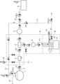
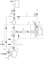
- FIG. 1 is a schematic diagram of a transportation device 100 according to the present embodiment. It is a system flow diagram during normal operation. It is a system flow diagram at the time of ammonia replenishment.
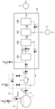
- FIG. 4 is a configuration diagram of a reformer 4 in Example 1.
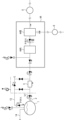
- FIG. FIG. 2 is a configuration diagram of a reformer 24 in Example 2.
- FIG. 3 is a configuration diagram of a reformer 34 in Example 3.
- FIG. 4 is a configuration diagram of a reformer 44 in Example 4.
- FIG. 1 is a schematic diagram showing a transportation device 100 equipped with a power generation system of this embodiment.
- the power generation system of this embodiment includes an ammonia tank 1 (first container) that stores ammonia as an energy source, a hydrogen generator A that reformes ammonia to generate hydrogen and nitrogen, and a hydrogen generator A that generates hydrogen and nitrogen by reforming ammonia. It consists of an internal combustion engine 8 that is used as fuel. Alternatively, a configuration may be adopted in which a fuel cell and a prime mover are provided in place of the internal combustion engine 8, electricity is generated using only hydrogen generated by the hydrogen generator A, and the prime mover is driven by electricity.
- Transportation equipment 100 equipped with this system includes ships, automobiles, trains, aircraft, and the like.
- a ship according to an embodiment of the present invention has the above system mounted on its hull.
- ship types include bulk carriers, container ships, liquefied gas carriers, crude oil tankers, ferries, RORO ships, car carriers, passenger ships, and the like.
- FIG. 2 shows the flow of the system when the power generation system is in normal operation.
- Liquid ammonia is filled into the ammonia tank 1 from the bunkering line 14. The liquid ammonia is then sent to the vaporizer 3 through the ammonia supply line 2 via the control valve V1. In the vaporizer 3, liquid ammonia is vaporized and sent to the reformer 4 via the control valve V2.
- the reformer 4 forms part of a hydrogen generator A that reformes gaseous ammonia to generate hydrogen and nitrogen. Since the reformer 4 itself is a common device, a detailed explanation of the reformer 4 will be omitted here. Nitrogen generated in the reformer 4 is separated within the reformer 4, and stored under pressure in a nitrogen tank 5 (second container) using a general compressor. Nitrogen temporarily stored in the nitrogen tank 5 is supplied to a desired location as a purge gas. The supply of purge gas will be described later.
- Nitrogen which is an inert gas, can be used as a purge gas to purge the hydrogen supply line 7.
- nitrogen is supplied to the outer pipe 7b of the hydrogen supply line 7 that supplies hydrogen.
- nitrogen is also supplied to the inner tube 7a.
- the internal combustion engine 8 of this embodiment generates power using hydrogen produced by reforming ammonia onboard the ship as fuel.
- the ship which is the transportation device 100, can be propelled by the power generated by the internal combustion engine 8.
- hydrogen fuel tank on board it is conceivable to have a hydrogen fuel tank on board and use hydrogen as fuel, but hydrogen has a large fuel volume as it is 4.5 times the volume of heavy oil even when it is liquid, and also because hydrogen needs to be kept in a liquefied state.
- the temperature must be kept at -253°C, which imposes strict requirements on the structure of the tank.
- hydrogen bunkering technology is still immature, and the supply infrastructure is also underdeveloped.
- there are problems such as the need to take measures against hydrogen leakage, BOG (boil-off gas), and tank brittleness.
- ammonia-burning ship that obtains power by directly burning ammonia in an internal combustion engine is also conceivable, but it would be necessary to establish combustion control for ammonia, which is flame retardant, and to take measures against N 2 O in exhaust gas. Additionally, there are problems such as the immature technology for burning ammonia exclusively.
- ammonia tank 1 by using ammonia as the primary fuel, it is possible to theoretically reduce the volume to about 2/3 of the hydrogen fuel tank. That is, as shown in the following equation, 2NH 3 ⁇ N 2 +3H 2
- ammonia tank 1 By reforming ammonia, it is possible to obtain hydrogen with a volume 1.5 times the volume of ammonia. In this way, the ammonia tank 1 can be made smaller than the hydrogen fuel tank.
- the hydrogen tank 6 is used as a temporary buffer tank for the generated hydrogen, there is no need to maintain the extremely low temperature (-253° C.) or take measures against BOG, which are required for a hydrogen fuel tank. Further, by using hydrogen obtained by reforming ammonia as a fuel, the problem of combustibility of ammonia and the problem of N 2 O generation can be solved at the same time.
- ammonia may be supplied from the ammonia tank 1 to the urea SCR 17.
- Nitrogen produced by reforming is pressurized and stored in a nitrogen tank 5.
- a fuel piping purge line 11 (first purge line) is connected from the nitrogen tank 5 to the hydrogen supply line 7.
- the hydrogen supply line 7 is a double pipe composed of an inner pipe 7a and an outer pipe 7b surrounding the outside thereof, and one end is connected to the internal combustion engine 8 and the other end is connected to the hydrogen generator A.
- Hydrogen, which is fuel, is supplied to the fuel valve of the internal combustion engine 8 through the inner pipe 7a.
- the area where the internal combustion engine 8 and the hydrogen supply line 7 are provided is the gas safe engine area B.
- This gas safe engine area B is provided with a ventilation port 15 for exhaust, and a pipe from the ventilation port 15 is connected to the outer pipe 7b of the hydrogen supply line 7.
- An exhaust fan 16 is connected to the hydrogen generator A. With the ventilation port 15 and the exhaust fan 16, the outer pipe 7b of the hydrogen supply line 7 and the hydrogen generator A can perform ventilation by feeding air at least 30 times per hour. Further, more preferably, ventilation may be performed 10 times per hour.
- a cargo hold purge line 12 (second purge line) is connected from the nitrogen tank 5 to the cargo hold 9.
- the produced nitrogen is supplied to the cargo hold 9 through the cargo hold purge line 12. Since this cargo hold 9 may store flammable substances such as crude oil, it is filled with nitrogen as an inert gas.
- the cargo hold 9 is purged with nitrogen from the cargo hold purge line 12. This is because flammable cargo, etc. must always be purged with inert gas.
- the purge gas by using nitrogen obtained by reforming ammonia as the purge gas, there is no need to additionally provide an inert gas supply device for supplying inert gas, and the cargo hold 9 can be expanded.
- This enables effective use of space, such as by increasing the size of fuel tanks and fuel tanks. Furthermore, since no additional equipment is required, costs can be reduced.
- FIG. 4 shows the configuration around the reformer 4 of the first embodiment.
- the ammonia vaporized in the vaporizer 3 is reformed in the catalyst tank 4A in the reformer 4, and the reformed gas contains hydrogen (broken arrow), nitrogen (solid arrow), and residual ammonia (dotted chain arrow). It will be done.
- Hydrogen is separated from these gases by a hydrogen separation PSA device 4C (Pressure Swing Adsorption) placed downstream of the catalyst tank 4A, and the separated hydrogen is sent to the hydrogen output pipe of the hydrogen separation PSA device 4C. Sent to tank 6.
- PSA device 4C Pressure Swing Adsorption
- nitrogen is separated from the gas containing nitrogen and residual ammonia that was not separated by the hydrogen separation PSA device 4C by the nitrogen separation PSA device 4B arranged downstream of the hydrogen separation PSA device 4C.
- the separated nitrogen is sent to the nitrogen tank 5 from the nitrogen output piping of the nitrogen separation PSA device 4B. Note that the residual ammonia left after the separation in the nitrogen separation PSA device 4B contains some residual nitrogen.
- the residual ammonia is liquefied by the reliquefaction device 4D located downstream of the nitrogen separation PSA device 4B, and the residual nitrogen is separated during this liquefaction. Then, it is returned upstream of the vaporizer 3 as liquid ammonia.
- the reliquefaction device 4D used in Example 1 is composed of a compressor. Since ammonia can be liquefied by pressurizing it to 8 atmospheres or more at room temperature, ammonia is easily liquefied in this reliquefaction device 4D. Note that the reliquefaction device 4D is equipped with a safety valve V5 for safety.
- Example 1 since the purity of hydrogen is high, a fuel cell and a prime mover are provided instead of an internal combustion engine 8, and the fuel cell generates electricity using only the hydrogen generated by the reformer 4 of the hydrogen generator A. However, this electricity may be used to drive a prime mover to generate power. In this way, in Example 1, since high-purity hydrogen is combusted, it is possible to reduce greenhouse gas emissions to almost zero.
- FIG. 5 shows the configuration around the reformer 24 of the second embodiment.
- the ammonia vaporized in the vaporizer 3 is reformed in the catalyst tank 24A in the reformer 24, and the reformed gas contains hydrogen, nitrogen, and residual ammonia, as in Example 1. Residual ammonia in these gases is liquefied by a reliquefaction device 24D disposed downstream of the catalyst tank 24A, and returned to the upstream side of the vaporizer 3 as liquid ammonia.
- the reliquefaction device 24D used in Example 2 is composed of a cooler. Since ammonia can be liquefied by cooling to -33 degrees or less, for example, ammonia is easily liquefied in this reliquefaction device 24D.
- hydrogen is separated from the gas containing hydrogen and nitrogen that has passed through the reliquefaction device 24D by a hydrogen separation PSA device 24C disposed downstream of the reliquefaction device 24D, and the separated hydrogen is transferred to hydrogen separation PSA device 24C. It is sent to the hydrogen tank 6 from the output pipe.
- the nitrogen that was not separated by the hydrogen separation PSA device 24C contains some residual hydrogen, and the nitrogen is separated from this gas by the nitrogen separation PSA device 24B located downstream of the hydrogen separation PSA device 24C. Ru.
- the separated nitrogen is sent to the nitrogen tank 5 from the nitrogen output piping of the nitrogen separation PSA device 24B. Note that residual hydrogen left during the separation in the nitrogen separation PSA device 24B is sent to the hydrogen tank 6. Further, since it is difficult to completely separate nitrogen with the nitrogen separation PSA device 24B, some nitrogen is also sent to the hydrogen tank 6.
- the purity of hydrogen is about 90%, the remainder is about 10% nitrogen, residual ammonia is completely removed, and high purity hydrogen and some nitrogen are supplied to the internal combustion engine 8. Ru.
- the second embodiment of the present invention also provides the same effects as the first embodiment.
- FIG. 6 shows the configuration around the reformer 34 of the third embodiment.
- the ammonia vaporized in the vaporizer 3 is reformed in the catalyst tank 34A in the reformer 34, and the reformed gas contains hydrogen, nitrogen, and residual ammonia, as in Example 1.
- the hydrogen separation PSA device 24C in the second embodiment is omitted, and the nitrogen separation PSA device 24B is replaced by a nitrogen membrane separation device 34B using membrane separation.
- the gas not separated by the nitrogen membrane separator 34B contains hydrogen, and this gas is sent to the hydrogen tank 6 from an output pipe different from the nitrogen output pipe of the nitrogen membrane separator 34B.
- FIG. 7 shows the configuration around the reformer 44 of the fourth embodiment.
- the ammonia vaporized in the vaporizer 3 is reformed in the catalyst tank 44A in the reformer 44, and the reformed gas contains hydrogen, nitrogen, and residual ammonia, as in Example 1.
- the reliquefaction device 34D in the third embodiment is omitted.
Landscapes
- Engineering & Computer Science (AREA)
- Chemical & Material Sciences (AREA)
- Combustion & Propulsion (AREA)
- Mechanical Engineering (AREA)
- Ocean & Marine Engineering (AREA)
- Chemical Kinetics & Catalysis (AREA)
- General Chemical & Material Sciences (AREA)
- Life Sciences & Earth Sciences (AREA)
- Sustainable Development (AREA)
- Sustainable Energy (AREA)
- Organic Chemistry (AREA)
- Electrochemistry (AREA)
- Manufacturing & Machinery (AREA)
- Oil, Petroleum & Natural Gas (AREA)
- General Engineering & Computer Science (AREA)
- Inorganic Chemistry (AREA)
- Health & Medical Sciences (AREA)
- General Health & Medical Sciences (AREA)
- Transportation (AREA)
- Power Engineering (AREA)
- Output Control And Ontrol Of Special Type Engine (AREA)
- Filling Or Discharging Of Gas Storage Vessels (AREA)
- Fuel Cell (AREA)
Abstract
Description
2NH3→N2+3H2
アンモニアを改質することにより、アンモニアの体積の1.5倍の体積の水素を得ることができる。このようにしてアンモニアタンク1は、水素燃料タンクに対して小型化することができる。
本発明の実施例1について、図4を用いて説明をする。図4は、実施例1の改質器4の周辺の構成を示す。気化器3で気化したアンモニアは、改質器4における触媒槽4Aで改質され、改質されたガスには水素(破線矢印)、窒素(実線矢印)及び残留アンモニア(一点鎖線矢印)が含まれる。これらのガスは、触媒槽4Aの下流に配置された水素分離PSA装置4C(Pressure Swing Adsorption、圧力変動吸着)により水素が分離され、分離された水素は水素分離PSA装置4Cの水素出力配管から水素タンク6へ送られる。
次に、本発明の実施例2について図5を用いて説明をする。図5は、実施例2の改質器24の周辺の構成を示す。気化器3で気化したアンモニアは、改質器24における触媒槽24Aで改質され、改質されたガスには水素、窒素及び残留アンモニアが含まれることは実施例1と同じである。これらのガスは、触媒槽24Aの下流に配置された再液化装置24Dによってガス中の残留アンモニアが液化され、液体のアンモニアとして気化器3の上流に還元される。
次に、本発明の実施例3について図6を用いて説明をする。図6は、実施例3の改質器34の周辺の構成を示す。気化器3で気化したアンモニアは、改質器34における触媒槽34Aで改質され、改質されたガスには水素、窒素及び残留アンモニアが含まれることは実施例1と同じである。実施例3は、実施例2と比較して、実施例2における水素分離PSA装置24Cが省略され、更に窒素分離PSA装置24Bに代わって膜分離による窒素膜分離装置34Bを備えた構成である。
次に、本発明の実施例4について図7を用いて説明をする。図7は、実施例4の改質器44の周辺の構成を示す。気化器3で気化したアンモニアは、改質器44における触媒槽44Aで改質され、改質されたガスには水素、窒素及び残留アンモニアが含まれることは実施例1と同じである。実施例4は、実施例3と比較して、実施例3における再液化装置34Dが省略された構成である。
5 窒素タンク(第2の容器)
7 水素供給ライン
8 内燃機関
9 貨物艙
100 輸送機器
A 水素生成装置
P1 供給圧力
P2 圧力
Claims (11)
- アンモニアを貯蔵する第1の容器と、
前記アンモニアを改質して水素と窒素とを生成する水素生成装置と、
を備える輸送機器であって、
前記水素が燃料として使用されることを特徴とする、輸送機器。 - 前記水素生成装置で生成された前記窒素を貯蔵する第2の容器を更に備え、
前記窒素は、パージガスとして供給されることを特徴とする、請求項1に記載の輸送機器。 - 前記パージガスを供給する際は、前記パージガスは、前記水素を供給する水素供給ラインへ供給されることを特徴とする請求項2に記載の輸送機器。
- 前記水素供給ラインにおいて、前記パージガスの流れる方向は、前記水素が供給される方向と逆向きであることを特徴とする請求項3に記載の輸送機器。
- 前記パージガスは、前記水素の供給圧力より高い圧力で前記水素供給ラインへ供給されることを特徴とする請求項3又は4に記載の輸送機器。
- 貨物艙を備え、
前記パージガスは、前記貨物艙へ供給されることを特徴とする請求項2乃至5の何れか1項に記載の輸送機器。 - 前記パージガスは、前記第1の容器へ供給されることを特徴とする請求項2乃至6の何れか1項に記載の輸送機器。
- 前記輸送機器は、船舶であることを特徴とする、請求項1乃至7の何れか1項に記載の輸送機器。
- 内燃機関を備え、
前記内燃機関は、前記水素生成装置により生成された前記水素のみを燃料として動力を発生し、前記動力により駆動されることを特徴とする、請求項1乃至8の何れか1項に記載の輸送機器。 - 内燃機関を備え、
前記内燃機関は、前記水素生成装置により生成された前記水素と前記アンモニアとを混焼して動力を発生し、前記動力により駆動されることを特徴とする、請求項1乃至8の何れか1項に記載の輸送機器。 - 燃料電池と原動機とを備え、
前記燃料電池は、前記水素生成装置により生成された前記水素を用いて電気を発生し、前記電気により前記原動機が駆動されることを特徴とする、請求項1乃至8の何れか1項に記載の輸送機器。
Priority Applications (4)
| Application Number | Priority Date | Filing Date | Title |
|---|---|---|---|
| EP22818162.4A EP4265515A4 (en) | 2022-03-10 | 2022-03-17 | TRANSPORTATION DEVICE |
| CN202280005103.XA CN117043059A (zh) | 2022-03-10 | 2022-03-17 | 运输设备 |
| US18/010,984 US12401051B2 (en) | 2022-03-10 | 2022-03-17 | Transport equipment |
| KR1020227043841A KR102939976B1 (ko) | 2022-03-10 | 2022-03-17 | 수송 기기 |
Applications Claiming Priority (2)
| Application Number | Priority Date | Filing Date | Title |
|---|---|---|---|
| JP2022-037181 | 2022-03-10 | ||
| JP2022037181A JP7105021B1 (ja) | 2022-03-10 | 2022-03-10 | 輸送機器 |
Publications (1)
| Publication Number | Publication Date |
|---|---|
| WO2023170983A1 true WO2023170983A1 (ja) | 2023-09-14 |
Family
ID=82493178
Family Applications (1)
| Application Number | Title | Priority Date | Filing Date |
|---|---|---|---|
| PCT/JP2022/012280 Ceased WO2023170983A1 (ja) | 2022-03-10 | 2022-03-17 | 輸送機器 |
Country Status (6)
| Country | Link |
|---|---|
| US (1) | US12401051B2 (ja) |
| EP (1) | EP4265515A4 (ja) |
| JP (1) | JP7105021B1 (ja) |
| KR (1) | KR102939976B1 (ja) |
| CN (1) | CN117043059A (ja) |
| WO (1) | WO2023170983A1 (ja) |
Families Citing this family (9)
| Publication number | Priority date | Publication date | Assignee | Title |
|---|---|---|---|---|
| US12000333B2 (en) | 2021-05-14 | 2024-06-04 | AMOGY, Inc. | Systems and methods for processing ammonia |
| KR102814660B1 (ko) * | 2022-08-03 | 2025-05-29 | 삼성중공업 주식회사 | 암모니아 연료 선박 |
| WO2024081632A1 (en) * | 2022-10-11 | 2024-04-18 | Amogy Inc. | Systems and methods for processing ammonia |
| JP2024100164A (ja) * | 2023-01-13 | 2024-07-26 | 愛三工業株式会社 | 燃料供給装置 |
| CN120898069A (zh) * | 2023-05-19 | 2025-11-04 | 株式会社拯救星球 | 点火方法 |
| CN121712846A (zh) | 2023-08-14 | 2026-03-20 | 佳能株式会社 | 树脂组合物、树脂组合物的制造方法、粒料、成形体、注射成形体和设备 |
| GB2635309A (en) * | 2023-09-14 | 2025-05-14 | Lge Ip Man Company Limited | Method and system for recovering fuel from an engine |
| JP7848252B2 (ja) * | 2024-01-22 | 2026-04-20 | 株式会社三井E&S | 高圧水素ガス配管からの水素ガス漏洩検知システム |
| US20250327427A1 (en) * | 2024-04-17 | 2025-10-23 | Caterpillar Inc. | Systems and methods for venting a pressurized fluid used as a fuel in an engine |
Citations (6)
| Publication number | Priority date | Publication date | Assignee | Title |
|---|---|---|---|---|
| JPH0559475B2 (ja) | 1986-04-30 | 1993-08-31 | Tokyo Shibaura Electric Co | |
| US20110011354A1 (en) * | 2008-02-19 | 2011-01-20 | Ibrahim Dincer | Methods and apparatus for using ammonia as sustainable fuel, refrigerant and NOx reduction agent |
| JP2013517986A (ja) * | 2010-01-29 | 2013-05-20 | シーメンス アクティエンゲゼルシャフト | 電気駆動航空機 |
| KR20180124365A (ko) * | 2017-05-11 | 2018-11-21 | 삼성중공업 주식회사 | 동력발생장치 |
| KR20210145031A (ko) * | 2020-05-22 | 2021-12-01 | 대우조선해양 주식회사 | 선박용 연료 공급 시스템 |
| JP2022037181A (ja) | 2019-11-12 | 2022-03-08 | 東京応化工業株式会社 | 化学増幅型感光性組成物、感光性ドライフィルムの製造方法及びパターン化されたレジスト膜の製造方法 |
Family Cites Families (7)
| Publication number | Priority date | Publication date | Assignee | Title |
|---|---|---|---|---|
| JP6566639B2 (ja) * | 2015-01-05 | 2019-08-28 | 大阪瓦斯株式会社 | 水素製造装置の運転方法および水素製造装置 |
| JP5870341B1 (ja) * | 2015-05-29 | 2016-02-24 | 株式会社フクハラ | 舶用防爆パージガス供給システム |
| NO343554B1 (no) * | 2017-08-14 | 2019-04-01 | Lars Harald Heggen | Nullutslipps fremdriftssystem og generatoranlegg med ammoniakk som brennstoff |
| KR102755813B1 (ko) | 2020-05-13 | 2025-01-20 | 한화오션 주식회사 | 선박용 연료 공급 시스템 |
| JP6859475B1 (ja) | 2020-08-06 | 2021-04-14 | 三菱造船株式会社 | 船舶 |
| KR102298854B1 (ko) * | 2021-01-27 | 2021-09-09 | 주식회사 트랜스가스솔루션 | 선박의 연료 공급 시스템 |
| CN113623089B (zh) * | 2021-08-11 | 2023-01-24 | 中国船舶重工集团柴油机有限公司 | 一种船用氨供给系统及船舶 |
-
2022
- 2022-03-10 JP JP2022037181A patent/JP7105021B1/ja active Active
- 2022-03-17 EP EP22818162.4A patent/EP4265515A4/en active Pending
- 2022-03-17 CN CN202280005103.XA patent/CN117043059A/zh active Pending
- 2022-03-17 KR KR1020227043841A patent/KR102939976B1/ko active Active
- 2022-03-17 US US18/010,984 patent/US12401051B2/en active Active
- 2022-03-17 WO PCT/JP2022/012280 patent/WO2023170983A1/ja not_active Ceased
Patent Citations (6)
| Publication number | Priority date | Publication date | Assignee | Title |
|---|---|---|---|---|
| JPH0559475B2 (ja) | 1986-04-30 | 1993-08-31 | Tokyo Shibaura Electric Co | |
| US20110011354A1 (en) * | 2008-02-19 | 2011-01-20 | Ibrahim Dincer | Methods and apparatus for using ammonia as sustainable fuel, refrigerant and NOx reduction agent |
| JP2013517986A (ja) * | 2010-01-29 | 2013-05-20 | シーメンス アクティエンゲゼルシャフト | 電気駆動航空機 |
| KR20180124365A (ko) * | 2017-05-11 | 2018-11-21 | 삼성중공업 주식회사 | 동력발생장치 |
| JP2022037181A (ja) | 2019-11-12 | 2022-03-08 | 東京応化工業株式会社 | 化学増幅型感光性組成物、感光性ドライフィルムの製造方法及びパターン化されたレジスト膜の製造方法 |
| KR20210145031A (ko) * | 2020-05-22 | 2021-12-01 | 대우조선해양 주식회사 | 선박용 연료 공급 시스템 |
Non-Patent Citations (1)
| Title |
|---|
| See also references of EP4265515A4 |
Also Published As
| Publication number | Publication date |
|---|---|
| US20240234769A1 (en) | 2024-07-11 |
| KR102939976B1 (ko) | 2026-03-16 |
| CN117043059A (zh) | 2023-11-10 |
| US12401051B2 (en) | 2025-08-26 |
| KR20230133756A (ko) | 2023-09-19 |
| EP4265515A4 (en) | 2024-12-18 |
| EP4265515A1 (en) | 2023-10-25 |
| JP2023132069A (ja) | 2023-09-22 |
| JP7105021B1 (ja) | 2022-07-22 |
Similar Documents
| Publication | Publication Date | Title |
|---|---|---|
| JP7105021B1 (ja) | 輸送機器 | |
| KR102755885B1 (ko) | 선박용 연료 공급 시스템 | |
| CN111469981B (zh) | 一种双燃料集装箱运输船 | |
| KR102663784B1 (ko) | 선박의 이중관시스템, 그 설치방법 및 그에 의한 암모니아 배출방법 | |
| KR20230136859A (ko) | 액화수소 운반선 | |
| KR102856823B1 (ko) | 선박의 통합형 가스 생성 시스템 및 방법 | |
| KR20240161659A (ko) | 부체 및 이산화탄소 회수 방법 | |
| KR102664944B1 (ko) | 선박의 암모니아 분해 시스템 및 방법 | |
| KR20210141818A (ko) | 선박용 연료 공급 시스템 | |
| KR20230165987A (ko) | 선박의 암모니아 연료공급시스템 | |
| KR102781718B1 (ko) | 선박용 연료 공급 시스템 | |
| JP7519136B1 (ja) | メタノール燃料船 | |
| KR102713857B1 (ko) | 부유식 저장 발전 설비 | |
| WO2023167594A1 (en) | Hydrocarbon production system with reduced carbon dioxide emission | |
| KR20230165989A (ko) | 선박의 암모니아 연료공급시스템 | |
| KR102697412B1 (ko) | 부유식 저장 발전 설비 | |
| KR102694828B1 (ko) | 무탄소 연료를 이용하는 선박 운항 시스템 | |
| KR102697408B1 (ko) | 부유식 저장 발전 설비 | |
| KR102937870B1 (ko) | 연료전지용 암모니아 회수 시스템 및 방법 | |
| KR102715407B1 (ko) | 부유식 저장 발전 설비 | |
| KR102945725B1 (ko) | 이산화탄소 운반선의 증발가스처리시스템 | |
| KR20250175039A (ko) | 암모니아 처리 시스템 및 이를 포함하는 선박 | |
| KR20260049925A (ko) | 연료전지용 연료공급시스템 및 이를 이용한 연료전지 추진 선박 | |
| KR20240141006A (ko) | 선박의 연료전지용 암모니아 연료 공급 시스템 | |
| KR20250096137A (ko) | 선박의 질소공급시스템 |
Legal Events
| Date | Code | Title | Description |
|---|---|---|---|
| WWE | Wipo information: entry into national phase |
Ref document number: 18010984 Country of ref document: US |
|
| WWE | Wipo information: entry into national phase |
Ref document number: 202280005103.X Country of ref document: CN |
|
| ENP | Entry into the national phase |
Ref document number: 2022818162 Country of ref document: EP Effective date: 20230502 |
|
| NENP | Non-entry into the national phase |
Ref country code: DE |
|
| WWE | Wipo information: entry into national phase |
Ref document number: 11202406071R Country of ref document: SG |
|
| WWG | Wipo information: grant in national office |
Ref document number: 18010984 Country of ref document: US |
|
| WWG | Wipo information: grant in national office |
Ref document number: 11202406071R Country of ref document: SG |
|
| WWP | Wipo information: published in national office |
Ref document number: 11202406071R Country of ref document: SG |