WO2023171110A1 - 流体圧アクチュエータ - Google Patents
流体圧アクチュエータ Download PDFInfo
- Publication number
- WO2023171110A1 WO2023171110A1 PCT/JP2023/000326 JP2023000326W WO2023171110A1 WO 2023171110 A1 WO2023171110 A1 WO 2023171110A1 JP 2023000326 W JP2023000326 W JP 2023000326W WO 2023171110 A1 WO2023171110 A1 WO 2023171110A1
- Authority
- WO
- WIPO (PCT)
- Prior art keywords
- fluid pressure
- pressure actuator
- actuator
- sealing member
- tube
- Prior art date
- Legal status (The legal status is an assumption and is not a legal conclusion. Google has not performed a legal analysis and makes no representation as to the accuracy of the status listed.)
- Ceased
Links
Images




Classifications
-
- B—PERFORMING OPERATIONS; TRANSPORTING
- B25—HAND TOOLS; PORTABLE POWER-DRIVEN TOOLS; MANIPULATORS
- B25J—MANIPULATORS; CHAMBERS PROVIDED WITH MANIPULATION DEVICES
- B25J15/00—Gripping heads and other end effectors
- B25J15/08—Gripping heads and other end effectors having finger members
- B25J15/12—Gripping heads and other end effectors having finger members with flexible finger members
-
- F—MECHANICAL ENGINEERING; LIGHTING; HEATING; WEAPONS; BLASTING
- F15—FLUID-PRESSURE ACTUATORS; HYDRAULICS OR PNEUMATICS IN GENERAL
- F15B—SYSTEMS ACTING BY MEANS OF FLUIDS IN GENERAL; FLUID-PRESSURE ACTUATORS, e.g. SERVOMOTORS; DETAILS OF FLUID-PRESSURE SYSTEMS, NOT OTHERWISE PROVIDED FOR
- F15B15/00—Fluid-actuated devices for displacing a member from one position to another; Gearing associated therewith
- F15B15/08—Characterised by the construction of the motor unit
- F15B15/10—Characterised by the construction of the motor unit the motor being of diaphragm type
- F15B15/103—Characterised by the construction of the motor unit the motor being of diaphragm type using inflatable bodies that contract when fluid pressure is applied, e.g. pneumatic artificial muscles or McKibben-type actuators
-
- B—PERFORMING OPERATIONS; TRANSPORTING
- B25—HAND TOOLS; PORTABLE POWER-DRIVEN TOOLS; MANIPULATORS
- B25J—MANIPULATORS; CHAMBERS PROVIDED WITH MANIPULATION DEVICES
- B25J15/00—Gripping heads and other end effectors
- B25J15/0023—Gripper surfaces directly activated by a fluid
-
- B—PERFORMING OPERATIONS; TRANSPORTING
- B25—HAND TOOLS; PORTABLE POWER-DRIVEN TOOLS; MANIPULATORS
- B25J—MANIPULATORS; CHAMBERS PROVIDED WITH MANIPULATION DEVICES
- B25J9/00—Program-controlled manipulators
- B25J9/10—Program-controlled manipulators characterised by positioning means for manipulator elements
- B25J9/14—Program-controlled manipulators characterised by positioning means for manipulator elements fluid
- B25J9/142—Program-controlled manipulators characterised by positioning means for manipulator elements fluid comprising inflatable bodies
-
- F—MECHANICAL ENGINEERING; LIGHTING; HEATING; WEAPONS; BLASTING
- F16—ENGINEERING ELEMENTS AND UNITS; GENERAL MEASURES FOR PRODUCING AND MAINTAINING EFFECTIVE FUNCTIONING OF MACHINES OR INSTALLATIONS; THERMAL INSULATION IN GENERAL
- F16L—PIPES; JOINTS OR FITTINGS FOR PIPES; SUPPORTS FOR PIPES, CABLES OR PROTECTIVE TUBING; MEANS FOR THERMAL INSULATION IN GENERAL
- F16L57/00—Protection of pipes or objects of similar shape against external or internal damage or wear
Definitions
- the present invention relates to a fluid pressure actuator.
- a fluid pressure actuator also called a "McKibben-type fluid pressure actuator”
- a fluid pressure actuator is used not only as a lift part (robot arm) for lifting an object, but also as a grip part (finger robot hand) for realizing the behavior of a human finger.
- an object of the present invention is to provide a fluid pressure actuator having a structure in which a cover member attached to a sealing member is difficult to come off.
- the gist of the present invention is as follows. It is a stretchable structure consisting of a cylindrical tube that expands and contracts depending on the pressure of fluid, and fiber cords oriented in a predetermined direction.
- a fluid pressure actuator comprising a sealing member that seals an end,
- a fluid pressure actuator characterized in that a bamboo shoot portion is formed on a free end side of the sealing member to enable locking and holding of a cover member separate from the fluid pressure actuator.
- a fluid pressure actuator having a structure in which a cover member attached to a sealing member is difficult to come off.
- FIG. 2 is a partially exploded perspective view of the fluid pressure actuator.
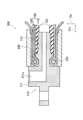
- FIG. 2 is a partial cross-sectional view along the axial direction DAX of a fluid pressure actuator including a sealing mechanism.
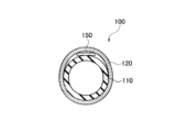
- FIG. 3 is a cross-sectional view of the actuator main body along the radial direction DR. It is an explanatory view of behavior of a fluid pressure actuator.
- FIG. 2 is a diagram showing an example of the configuration of a robot hand using a fluid pressure actuator. It is a schematic perspective view of the sealing member of the fluid pressure actuator of this embodiment with the cover member attached.
- FIG. 1 They are a schematic perspective view (upper figure) of a sealing member of the fluid pressure actuator of the present embodiment and a schematic perspective view (lower figure) of a cover member attached to the sealing member. It is a figure for explaining the cross-sectional shape of a bamboo shoot part.
- FIG. 1 is a side view of a fluid pressure actuator 10 according to this embodiment.
- the fluid pressure actuator 10 includes an actuator main body 100, a sealing mechanism 200, and a sealing mechanism 300. Furthermore, connecting portions 20 are provided at both ends of the fluid pressure actuator 10, respectively.
- the actuator main body 100 is composed of a tube 110 and a sleeve 120. Fluid flows into the actuator main body 100 through the connection port 211a.
- the actuator main body 100 contracts in the axial direction DAX and expands in the radial direction DR due to the inflow of fluid into the tube 110. Further, the actuator main body 100 expands in the axial direction DAX and contracts in the radial direction DR due to fluid flowing out from the tube 110. Due to such a shape change of the actuator main body 100, the fluid pressure actuator 10 exhibits its function as an actuator.
- Such a fluid pressure actuator 10 is a so-called McKibben type, and can be used not only for artificial muscles but also for robot limbs (upper limbs, lower limbs, etc.) that require higher capacity (contractile force). It can be suitably used.
- the connecting portion 20 is connected to members constituting the limb.
- a McKibben-type fluid pressure actuator having such basic characteristics is used, and a restraining member 150 (FIG. 1 (not shown, see FIGS. 2, 3, etc.), it is possible to curve (curl) in the orthogonal direction perpendicular to the axial direction DAX, that is, in the radial direction DR.
- the fluid used to drive the fluid pressure actuator 10 may be either a gas such as air or a liquid such as water or mineral oil, but the fluid pressure actuator 10 is particularly suitable for hydraulic drive where high pressure is applied to the actuator body 100. It has high durability that can withstand even
- the sealing mechanism 200 and the sealing mechanism 300 seal both ends of the actuator main body 100 in the axial direction DAX.
- the sealing mechanism 200 includes a sealing member 210 and a caulking member 230.
- the sealing member 210 seals the end of the actuator main body 100 in the axial direction DAX.
- the caulking member 230 caulks the actuator main body portion 100 together with the sealing member 210.
- An indentation 231 is formed on the outer peripheral surface of the caulking member 230, which is a trace of the caulking member 230 being caulked with a jig.
- the difference between the sealing mechanism 200 and the sealing mechanism 300 is whether a connection port 211a is provided and whether a protrusion 400, which will be described later, is provided. Therefore, except for these points, the structure of the sealing mechanism 300 is similar to the structure representatively described for the sealing mechanism 200.
- the fluid that has flowed in through the connection port 211a passes through a passage hole (not shown) and flows into the inside of the actuator main body 100, specifically, into the inside of the tube 110.
- FIG. 2 is a partially exploded perspective view of the fluid pressure actuator 10. As shown in FIG. 2, the fluid pressure actuator 10 includes an actuator main body 100 and a sealing mechanism 200.
- the actuator main body 100 is composed of the tube 110 and the sleeve 120, as described above.
- the tube 110 is a cylindrical body that expands and contracts depending on the pressure of the fluid.
- the tube 110 is made of an elastic material such as butyl rubber because it repeatedly contracts and expands with fluid.
- NBR nonrile rubber
- it should be made of NBR (nitrile rubber), which has high oil resistance, or at least one selected from the group consisting of hydrogenated NBR, chloroprene rubber, and epichlorohydrin rubber. is preferred.
- the sleeve 120 has a cylindrical shape and covers the outer peripheral surface of the tube 110.
- the sleeve 120 is a stretchable structure in which fiber cords oriented in a predetermined direction are woven together, and the oriented cords intersect to form a repeated diamond shape. By having such a shape, the sleeve 120 deforms in a pantograph and follows the contraction and expansion of the tube 110 while regulating it.
- the cord constituting the sleeve 120 it is preferable to use a fiber cord of aromatic polyamide (aramid fiber) or polyethylene terephthalate (PET).
- the cord is not limited to these types of fiber cords, and for example, cords of high-strength fibers such as PBO fibers (polyparaphenylenebenzobisoxazole) may be used.
- a restraining member 150 is provided between the tube 110 and the sleeve 120.
- the restraint member 150 is not compressed in the axial direction DAX, but can be deformed only along the radial direction DR (which may also be referred to as the deflection direction). That is, the restraint member 150 resists compression along the axial direction DAX, and is deformable in the orthogonal direction (radial direction DR) perpendicular to the axial direction DAX.
- the restraining member 150 has a characteristic that it is difficult to deform along the axial direction DAX and is flexible along the radial direction DR.
- deformable may also mean “curvable” or “curlable”.
- the restraint member 150 also has a function of restraining (regulating) the expansion of the tube 110 (and sleeve 120) outward in the radial direction DR at a position on the outer circumference of the tube 110 where the restraint member 150 is provided. There is.
- the restraint member 150 is provided inside the sleeve 120, specifically, in the space inside the sleeve 120 in the radial direction, from one end side to the other end side in the axial direction DAX. Further, in this embodiment, the restraint member 150 is formed using a leaf spring.
- the dimensions of the leaf spring are not particularly limited, and may be selected depending on the size of the fluid pressure actuator 10 and the required force to be generated.
- the material of the leaf spring is not particularly limited, but typically any material that is easy to bend and strong against compression, such as metal such as stainless steel, may be used.
- the restraint member 150 may be formed of a thin plate of carbon fiber reinforced plastic (CFRP). Since CFRP is less susceptible to plastic deformation than metal, the fluid pressure actuator 10 easily returns to its original straight state after being bent.
- the sealing mechanism 200 seals the end of the actuator main body 100 in the axial direction DAX.
- the sealing mechanism 200 includes a sealing member 210, a locking ring 220, and a caulking member 230.
- the sealing member 210 is inserted into the tubular actuator main body 100. Specifically, the sealing member 210 has a head portion 211 and a body portion 212, and the body portion 212 is inserted into the tube 110.
- sealing member 210 a metal such as stainless steel can be suitably used, but the sealing member 210 is not limited to such a metal, and a hard plastic material or the like may also be used.
- the locking ring 220 locks the sleeve 120 to the sealing member 210. Specifically, the sleeve 120 is folded back outward in the radial direction DR via the locking ring 220 (not shown in FIG. 2, see FIG. 3).
- the locking ring 220 has a notch 221 that is partially cut out so that it can be engaged with the sealing member 210.
- the same materials as the sealing member 210 such as metals and hard plastic materials, natural fibers (natural fiber threads), rubber (for example, O-rings), and other materials can be used.
- the caulking member 230 caulks the actuator main body 100 together with the sealing member 210.
- the caulking member 230 is provided on the outer peripheral surface of the portion of the actuator body 100 into which the sealing member 210 is inserted, and caulks the actuator body 100 to the sealing member 210 .
- the caulking member 230 metals such as aluminum alloy, brass, and iron can be used.
- an indentation 231 as shown in FIG. 1 is formed on the caulking member 230.
- FIG. 3 is a partial cross-sectional view of the fluid pressure actuator 10 including the sealing mechanism 200 along the axial direction DAX.
- the tube 110 is inserted into the body portion 212. Further, the sleeve 120 is folded back to the outside in the radial direction DR via the locking ring 220.
- a restraint member 150 is provided inside the sleeve 120 in the radial direction DR. Specifically, restraining member 150 is provided between tube 110 and sleeve 120.
- the restraining member 150 is provided in a part of the actuator main body 100 in the circumferential direction. That is, the restraint member 150 is provided only in a portion of the tube 110 (and sleeve 120) in the circumferential direction.
- the restraint member 150 is provided from one end side to the other end side in the axial direction DAX of the actuator main body 100 (that is, the tube 110 and the sleeve 120). Specifically, the restraining member 150 may be provided from the sealing mechanism 200 to the sealing mechanism 300.
- the restraining member 150 does not necessarily have to be provided completely from the sealing mechanism 200 to the sealing mechanism 300, and the restraining member 150 does not necessarily have to be provided completely over the sealing mechanism 200 and the sealing mechanism 300 (especially when the free end is bent). The restraining member 150 does not need to extend to the sealing mechanism 300 side (where there is a high possibility of this).
- the caulking member 230 is larger than the outer diameter of the body portion 212 of the sealing member 210, and is inserted into the body portion 212 and caulked with a jig.
- the caulking member 230 caulks the actuator main body 100 together with the sealing member 210 .
- the caulking member 230 caulks the tube 110 inserted into the body portion 212 and the sleeve 120 located outside the tube 110 in the radial direction DR. That is, the caulking member 230 caulks the tube 110 and the sleeve 120 together with the sealing member 210.
- FIG. 4 is a cross-sectional view of the actuator main body 100 along the radial direction DR.
- the restraining member 150 is provided between the tube 110 and the sleeve 120.
- the restraint member 150 may be in close contact with the tube 110 and the sleeve 120, or some gap may be formed between the restraint member 150 and the tube 110 and/or the sleeve 120, and on the sides of the restraint member 150. I don't mind.
- the restraining member 150 is provided in a part of the tube 110 in the circumferential direction.
- the width of the restraint member 150 is not particularly limited, but if it is based on the outer diameter of the tube 110, it may be approximately half the outer diameter.
- the outer diameter of the tube 110 may be 11 mm
- the length of the contracting actuator main body 100 portion may be 185 mm
- the width of the restraining member 150 (plate spring) may be 6 mm and the thickness may be approximately 0.5 mm.
- the restraint member 150 has a flat plate shape, but it may be slightly curved along the cross-sectional shapes of the tube 110 and the sleeve 120 as long as it does not affect the way it bends.
- FIG. 5 is an explanatory diagram of the behavior of the fluid pressure actuator 10.
- the sealing mechanism 200 side is fixed, and the sealing mechanism 300 side is freely movable. That is, the sealing mechanism 200 side is a fixed end, and the sealing mechanism 300 side is a free end.
- the restraining member 150 formed of a hard member such as a leaf spring plays a role like a backbone, and the position opposite to the position on the outer periphery of the tube 110 and sleeve 120 where the restraining member 150 is provided (FIG.
- the restraining member 150 By expanding outward in the radial direction DR, the dimension of the fluid pressure actuator 10 in the axial direction DAX is shortened, and the fluid pressure actuator 10 (specifically, the actuator main body 100) is expanded along the direction D1. Bends.
- the direction D1 may also be referred to as a flexible direction.
- the restraint member 150 is provided between the rubber tube 110 and the sleeve 120, and is a member that resists compression in the axial direction DAX and can be deformed along the orthogonal direction (radial direction DR). , are arranged in a part of the actuator main body 100 in the circumferential direction.
- the restraint member 150 has high compression rigidity, so the restraint member The part where 150 is placed cannot be contracted.
- other parts of the actuator main body 100 tend to contract, so a force in a bending direction along the orthogonal direction (radial direction DR) is generated, and the parts curve with the restraint member 150 as the back surface.
- FIG. 6 shows an example of the configuration of a robot hand using the fluid pressure actuator 10. Specifically, FIG. 6 is a schematic side view of a system 30 including a robot hand.
- the robot hand is configured using a plurality of fluid pressure actuators 10.
- the system 30 includes a plurality of hydraulic actuators 10 , a pedestal 35 , a strut 40 , an actuator connection 50 , and an actuator connection 60 .
- the fluid pressure actuator 10 is a bendable McKibben-type actuator that includes the restraining member 150 as described above.
- a support section 40 is provided upright on the upper surface of the pedestal section 35. The upper end portion of the support portion 40 is folded back downward, and the actuator connection portion 50 is connected to the tip portion of the support portion 40 .
- a fluid pressure actuator 15 is suspended from the actuator connection portion 50.
- the fluid pressure actuator 15 is not provided with a restraining member like the fluid pressure actuator 10, is a general McKibben type actuator, and contracts and expands along the axial direction (arrow direction in the figure). That is, the fluid pressure actuator 15 simply changes its length in the axial direction, and cannot curve like the fluid pressure actuator 10.
- An actuator connection portion 60 is connected to the lower end of the fluid pressure actuator 15. A plurality of fluid pressure actuators 10 are suspended from the actuator connection portion 60 .
- the fluid pressure actuator 15 is larger than the fluid pressure actuator 10 and can generate a larger force.
- the plurality of fluid pressure actuators 10 suspended from the actuator connection part 60 are curved, they can realize a behavior similar to a human finger.
- the plurality of hydraulic actuators 10 can grip soft and fragile objects, such as chicken eggs, without damaging them. Further, the fluid pressure actuator 10 and the fluid pressure actuator 15 can also grip and lift an object that weighs more than a certain level, for example, a shot put shot (7.26 kg or more).
- the fluid pressure actuator 10 has a large bending angle, generates a large force, is easy to control the force (generated force is proportional to pressure), has a simple structure, and can directly touch the object being handled by coating the surface. It has the following characteristics. Furthermore, the restraint member 150 provided in the fluid pressure actuator 10 resists compression of the actuator main body 100 (specifically, the tube 110) in the axial direction DAX, and resists compression in the radial direction DR perpendicular to the axial direction DAX. It can be transformed into.
- the restraint member 150 is provided inside the tube 110, the size of the fluid pressure actuator 10 does not increase. Furthermore, the restraint member 150 can efficiently generate force in the bending direction.
- the fluid pressure actuator 10 it is possible to exert a larger force in the bending direction while avoiding an increase in size.
- the restraint member 150 is provided in a part of the tube 110 in the circumferential direction. Therefore, on the circumference of the actuator main body 100, there are parts that contract and parts that cannot contract, and when pressure is applied to the fluid pressure actuator 10, it moves in one direction (the side opposite to the side where the restraining member 150 is provided). curve. Thereby, force in the bending direction can be efficiently generated, and a larger force in the bending direction can be exerted.
- the restraining member 150 is provided between the tube 110 and the sleeve 120. Therefore, expansion of the tube 110 along the axial direction DAX can be effectively restrained (regulated). Thereby, force in the bending direction can be efficiently generated, and a larger force in the bending direction can be exerted.
- FIG. 7 is a schematic perspective view of the sealing member of the fluid pressure actuator of this embodiment, to which the cover member is attached.
- FIG. 8 is a schematic perspective view (upper view) of a sealing member of the fluid pressure actuator of this embodiment and a schematic perspective view (lower view) of a cover member attached to the sealing member.
- the fluid pressure actuator 10 of this embodiment includes a cover member 500 that is separate from the fluid pressure actuator 10 on the free end side of the sealing member 310.
- a bamboo shoot portion 400 that can be locked and held is formed.
- the bamboo shoot part 400 has a structure in which a plurality of truncated square pyramids each having an outer shape in which a small diameter part and a large diameter part are connected by a tapered surface are continuous along the axial direction of the fluid pressure actuator 10.
- a plurality of truncated square pyramids each having an outer shape in which a small diameter part and a large diameter part are connected by a tapered surface are continuous along the axial direction of the fluid pressure actuator 10.
- three truncated square pyramids are consecutively arranged in the axial direction, but the number can also be two or four or more.
- an annular step is formed by the maximum diameter of the large diameter portion of one truncated cone and the minimum diameter of the small diameter portion of the truncated square pyramid adjacent to the one truncated square pyramid. ing.
- the cover member 500 has an insertion hole 501, and the insertion hole 501 is configured to fit into the bamboo shoot portion 400. The effects of this embodiment will be explained below.
- the bamboo shoot portion 400 that can lock and hold the cover member 500, which is separate from the fluid pressure actuator 10, is formed on the free end side of the sealing member 310.
- the cover member 500 for example, made of rubber
- the fluid pressure actuator of this embodiment has a structure in which the cover member attached to the sealing member is difficult to come off.
- the thickness of the cover member 500 can be increased, so that the cover member 500 can be made less likely to be torn.
- a plurality of truncated square pyramids (or truncated cones, etc.) having an outer shape in which a small diameter part and a large diameter part are connected by a tapered surface are connected to the fluid pressure actuator 10. Since the structure is continuous along the axial direction, even when a tensile force is applied in the axial direction, an annular step (in the illustrated example, such steps are formed at three locations in the axial direction) ) acts as a resistance, making it even more difficult for the cover member 500 to come off from the sealing member 310. For example, even when the robot hand grips a heavy object, it is possible to effectively prevent the cover 500 member from coming off from the sealing member 310. From this point of view, it is more preferable that three or more of the above-mentioned truncated square pyramids (or truncated cones, etc.) are continuous in the axial direction.
- the sealing member 310 is preferably made of metal. If the sealing member 310 is made of metal, it is likely to slip between it and the object, but such slipping can be prevented by the cover member 500 (for example, made of rubber). Moreover, such a cover member 500 is easy to replace, and for example, cover members 500 made of different materials can be used depending on the object.
- FIG. 9 is a diagram for explaining the cross-sectional shape of the bamboo shoot part.
- the bamboo shoot portion 400 preferably has a non-circular cross-section, and more preferably an elliptical cross-section or a rectangular cross-section. This is because it is possible to suppress rotation of the cover member 500 around the axial direction when the cover member 500 is attached.
- the long axis of the bamboo shoot part 400 in the cross section is arranged in a direction perpendicular to the direction in which the fluid pressure actuator curves. This is because a contact area is ensured when gripping the object, making it possible to grip the object more stably.
Landscapes
- Engineering & Computer Science (AREA)
- Mechanical Engineering (AREA)
- General Engineering & Computer Science (AREA)
- Robotics (AREA)
- Chemical & Material Sciences (AREA)
- Analytical Chemistry (AREA)
- Physics & Mathematics (AREA)
- Fluid Mechanics (AREA)
- Actuator (AREA)
Abstract
Description
流体の圧力によって膨張及び収縮する円筒状のチューブと、所定方向に配向された繊維コードを編み込んだ伸縮性を有する構造体であり、前記チューブの外周面を覆うスリーブと、前記チューブの軸方向における端部を封止する封止部材と、を備えた、流体圧アクチュエータであって、
前記封止部材における自由端側に、前記流体圧アクチュエータとは別体のカバー部材を係止保持可能とするたけのこ部が形成されていることを特徴とする、流体圧アクチュエータ。
<<流体圧アクチュエータの全体概略構成>>
図1は、本実施形態に係る流体圧アクチュエータ10の側面図である。図1に示すように、流体圧アクチュエータ10は、アクチュエータ本体部100、封止機構200及び封止機構300を備える。また、流体圧アクチュエータ10の両端には、連結部20がそれぞれ設けられる。
図3は、封止機構200を含む流体圧アクチュエータ10の軸方向DAXに沿った一部断面図である。
図4は、アクチュエータ本体部100の径方向DRに沿った断面図である。図4に示すように、拘束部材150は、チューブ110とスリーブ120との間に設けられる。拘束部材150は、チューブ110及びスリーブ120と密着していてもよいし、拘束部材150と、チューブ110及び/またはスリーブ120との間、及び拘束部材150の側方には、多少隙間が形成されても構わない。
図5は、流体圧アクチュエータ10の挙動の説明図である。図5に示されている流体圧アクチュエータ10は、封止機構200側が固定されており、封止機構300側は自由に移動できる状態である。つまり、封止機構200側が固定端であり、封止機構300側が自由端である。
図6は、流体圧アクチュエータ10を用いたロボットハンドの構成例を示す。具体的には、図6は、ロボットハンドを備えたシステム30の概略側面図である。
また、流体圧アクチュエータ10に備えられる拘束部材150は、アクチュエータ本体部100( 具体的には、チューブ110)の軸方向DAXに沿った圧縮に対して抵抗し、軸方向DAXに直交する径方向DRに変形可能である。
以下、本実施形態の作用効果について説明する。
35:台座部、 40:支柱部、 50、60:アクチュエータ接続部、
100、100A、100B:アクチュエータ本体部、
110:チューブ、 120:スリーブ、 150、150A、150B:拘束部材、
151:ピアノ線、 160:離間部材、 200、200A:封止機構、
210:封止部材、 211:頭部、 211a:接続口、 212:胴体部、
220:係止リング、 221:切欠き部、 230:かしめ部材、
231:圧痕、 300:封止機構、 310:封止部材、
400:たけのこ部、 500:カバー部材
Claims (5)
- 流体の圧力によって膨張及び収縮する円筒状のチューブと、所定方向に配向された繊維コードを編み込んだ伸縮性を有する構造体であり、前記チューブの外周面を覆うスリーブと、前記チューブの軸方向における端部を封止する封止部材と、を備えた、流体圧アクチュエータであって、
前記封止部材における自由端側に、前記流体圧アクチュエータとは別体のカバー部材を係止保持可能とするたけのこ部が形成されていることを特徴とする、流体圧アクチュエータ。 - 前記たけのこ部は、断面非円形状である、請求項1に記載の流体圧アクチュエータ。
- 前記たけのこ部は、断面において、楕円形状又は長方形状である、請求項2に記載の流体圧アクチュエータ。
- 前記たけのこ部は、前記断面における長軸が前記流体圧アクチュエータの湾曲する方向と直交する方向に配置されている、請求項2又は3に記載の流体圧アクチュエータ。
- 前記封止部材は、金属製である、請求項1~4のいずれか一項に記載の流体圧アクチュエータ。
Priority Applications (3)
| Application Number | Priority Date | Filing Date | Title |
|---|---|---|---|
| EP23766291.1A EP4491884A4 (en) | 2022-03-08 | 2023-01-10 | HYDRAULIC ACTUATOR |
| CN202380024048.3A CN118786285A (zh) | 2022-03-08 | 2023-01-10 | 流体压力致动器 |
| US18/843,285 US20250188961A1 (en) | 2022-03-08 | 2023-01-10 | Fluid pressure actuator |
Applications Claiming Priority (2)
| Application Number | Priority Date | Filing Date | Title |
|---|---|---|---|
| JP2022-035715 | 2022-03-08 | ||
| JP2022035715A JP2023131049A (ja) | 2022-03-08 | 2022-03-08 | 流体圧アクチュエータ |
Publications (1)
| Publication Number | Publication Date |
|---|---|
| WO2023171110A1 true WO2023171110A1 (ja) | 2023-09-14 |
Family
ID=87936664
Family Applications (1)
| Application Number | Title | Priority Date | Filing Date |
|---|---|---|---|
| PCT/JP2023/000326 Ceased WO2023171110A1 (ja) | 2022-03-08 | 2023-01-10 | 流体圧アクチュエータ |
Country Status (5)
| Country | Link |
|---|---|
| US (1) | US20250188961A1 (ja) |
| EP (1) | EP4491884A4 (ja) |
| JP (1) | JP2023131049A (ja) |
| CN (1) | CN118786285A (ja) |
| WO (1) | WO2023171110A1 (ja) |
Families Citing this family (1)
| Publication number | Priority date | Publication date | Assignee | Title |
|---|---|---|---|---|
| JP2025089179A (ja) * | 2023-12-01 | 2025-06-12 | 株式会社ブリヂストン | 流体圧アクチュエータ |
Citations (3)
| Publication number | Priority date | Publication date | Assignee | Title |
|---|---|---|---|---|
| JPS57168891A (en) * | 1981-04-06 | 1982-10-18 | Mitsubishi Electric Corp | Element for actuator |
| JPH03113104A (ja) * | 1989-09-25 | 1991-05-14 | Bridgestone Corp | 湾曲可能なアクチュエータ |
| JP2000274410A (ja) * | 1999-03-24 | 2000-10-03 | Sanjo Kinzoku Kk | 棒・線状体固定具、棒・線状体挟持固定具 |
Family Cites Families (8)
| Publication number | Priority date | Publication date | Assignee | Title |
|---|---|---|---|---|
| US5185932A (en) * | 1982-06-03 | 1993-02-16 | Caines R Scott | Robotic fluid-actuated muscle analogue tree trimmer |
| JP2004358861A (ja) * | 2003-06-06 | 2004-12-24 | Funai Electric Co Ltd | インクカートリッジのノズルキャップホルダ |
| JP2009250362A (ja) * | 2008-04-07 | 2009-10-29 | Olympus Corp | アクチュエータ |
| JP6710029B2 (ja) * | 2015-08-31 | 2020-06-17 | ダイヤホールディングス株式会社 | アクチュエータ及び身体支援装置 |
| JP6889992B2 (ja) * | 2016-09-02 | 2021-06-18 | 株式会社ブリヂストン | 流体圧アクチュエータ |
| JP6928105B2 (ja) * | 2017-10-30 | 2021-09-01 | 株式会社ブリヂストン | 空気圧式アクチュエータ |
| JP2021088999A (ja) * | 2019-12-02 | 2021-06-10 | 株式会社ブリヂストン | 流体圧アクチュエータ |
| JP3231063U (ja) * | 2020-12-21 | 2021-03-11 | 株式会社レーベン | 樹脂構造体、カトラリー、及び文房具 |
-
2022
- 2022-03-08 JP JP2022035715A patent/JP2023131049A/ja active Pending
-
2023
- 2023-01-10 WO PCT/JP2023/000326 patent/WO2023171110A1/ja not_active Ceased
- 2023-01-10 CN CN202380024048.3A patent/CN118786285A/zh active Pending
- 2023-01-10 US US18/843,285 patent/US20250188961A1/en active Pending
- 2023-01-10 EP EP23766291.1A patent/EP4491884A4/en active Pending
Patent Citations (3)
| Publication number | Priority date | Publication date | Assignee | Title |
|---|---|---|---|---|
| JPS57168891A (en) * | 1981-04-06 | 1982-10-18 | Mitsubishi Electric Corp | Element for actuator |
| JPH03113104A (ja) * | 1989-09-25 | 1991-05-14 | Bridgestone Corp | 湾曲可能なアクチュエータ |
| JP2000274410A (ja) * | 1999-03-24 | 2000-10-03 | Sanjo Kinzoku Kk | 棒・線状体固定具、棒・線状体挟持固定具 |
Non-Patent Citations (1)
| Title |
|---|
| See also references of EP4491884A4 * |
Also Published As
| Publication number | Publication date |
|---|---|
| US20250188961A1 (en) | 2025-06-12 |
| EP4491884A1 (en) | 2025-01-15 |
| EP4491884A4 (en) | 2025-06-11 |
| CN118786285A (zh) | 2024-10-15 |
| JP2023131049A (ja) | 2023-09-21 |
Similar Documents
| Publication | Publication Date | Title |
|---|---|---|
| JP2021088999A (ja) | 流体圧アクチュエータ | |
| WO2023171111A1 (ja) | ロボットハンド | |
| JP7349338B2 (ja) | 流体圧アクチュエータ | |
| WO2023171110A1 (ja) | 流体圧アクチュエータ | |
| JP2010127429A (ja) | 流体アクチュエータ | |
| US20250326138A1 (en) | Fluid pressure actuator with cover | |
| EP4455490B1 (en) | Gripping device | |
| EP4450831A1 (en) | Gripping device | |
| WO2023171113A1 (ja) | ロボットハンド | |
| US12281662B2 (en) | Fluid pressure actuator | |
| EP4450829A1 (en) | Hydraulic actuator | |
| EP4450832A1 (en) | Gripping device | |
| JP7611808B2 (ja) | 把持装置 | |
| JP2023091136A (ja) | 把持装置 | |
| JP2023090524A (ja) | 流体圧アクチュエータ | |
| WO2023112446A1 (ja) | 流体圧アクチュエータ | |
| WO2024053292A1 (ja) | ロボットハンド |
Legal Events
| Date | Code | Title | Description |
|---|---|---|---|
| 121 | Ep: the epo has been informed by wipo that ep was designated in this application |
Ref document number: 23766291 Country of ref document: EP Kind code of ref document: A1 |
|
| WWE | Wipo information: entry into national phase |
Ref document number: 202380024048.3 Country of ref document: CN |
|
| WWE | Wipo information: entry into national phase |
Ref document number: 18843285 Country of ref document: US |
|
| WWE | Wipo information: entry into national phase |
Ref document number: 2023766291 Country of ref document: EP |
|
| NENP | Non-entry into the national phase |
Ref country code: DE |
|
| ENP | Entry into the national phase |
Ref document number: 2023766291 Country of ref document: EP Effective date: 20241008 |
|
| WWP | Wipo information: published in national office |
Ref document number: 18843285 Country of ref document: US |