WO2023171606A1 - 屈折特性測定装置 - Google Patents
屈折特性測定装置 Download PDFInfo
- Publication number
- WO2023171606A1 WO2023171606A1 PCT/JP2023/008295 JP2023008295W WO2023171606A1 WO 2023171606 A1 WO2023171606 A1 WO 2023171606A1 JP 2023008295 W JP2023008295 W JP 2023008295W WO 2023171606 A1 WO2023171606 A1 WO 2023171606A1
- Authority
- WO
- WIPO (PCT)
- Prior art keywords
- light
- optotype
- optical element
- aperture
- section
- Prior art date
- Legal status (The legal status is an assumption and is not a legal conclusion. Google has not performed a legal analysis and makes no representation as to the accuracy of the status listed.)
- Ceased
Links
Images





Classifications
-
- A—HUMAN NECESSITIES
- A61—MEDICAL OR VETERINARY SCIENCE; HYGIENE
- A61B—DIAGNOSIS; SURGERY; IDENTIFICATION
- A61B3/00—Apparatus for testing the eyes; Instruments for examining the eyes
- A61B3/02—Subjective types, i.e. testing apparatus requiring the active assistance of the patient
- A61B3/028—Subjective types, i.e. testing apparatus requiring the active assistance of the patient for testing visual acuity; for determination of refraction, e.g. phoropters
- A61B3/032—Devices for presenting test symbols or characters, e.g. test chart projectors
- A61B3/0325—Devices for presenting test symbols or characters, e.g. test chart projectors provided with red and green targets
-
- G—PHYSICS
- G01—MEASURING; TESTING
- G01M—TESTING STATIC OR DYNAMIC BALANCE OF MACHINES OR STRUCTURES; TESTING OF STRUCTURES OR APPARATUS, NOT OTHERWISE PROVIDED FOR
- G01M11/00—Testing of optical apparatus; Testing structures by optical methods not otherwise provided for
- G01M11/02—Testing optical properties
- G01M11/0228—Testing optical properties by measuring refractive power
-
- A—HUMAN NECESSITIES
- A61—MEDICAL OR VETERINARY SCIENCE; HYGIENE
- A61B—DIAGNOSIS; SURGERY; IDENTIFICATION
- A61B3/00—Apparatus for testing the eyes; Instruments for examining the eyes
- A61B3/10—Objective types, i.e. instruments for examining the eyes independent of the patients' perceptions or reactions
- A61B3/103—Objective types, i.e. instruments for examining the eyes independent of the patients' perceptions or reactions for determining refraction, e.g. refractometers, skiascopes
-
- G—PHYSICS
- G01—MEASURING; TESTING
- G01M—TESTING STATIC OR DYNAMIC BALANCE OF MACHINES OR STRUCTURES; TESTING OF STRUCTURES OR APPARATUS, NOT OTHERWISE PROVIDED FOR
- G01M11/00—Testing of optical apparatus; Testing structures by optical methods not otherwise provided for
- G01M11/02—Testing optical properties
- G01M11/0285—Testing optical properties by measuring material or chromatic transmission properties
Definitions
- the present invention relates to a refractive characteristic measuring device that measures the refractive characteristics of an eye.
- a refraction test is performed to measure the refractive properties of the eye.
- refraction tests there are known subjective tests in which the subject himself or herself identifies the visual target or light that is presented to him or her, and objective tests in which a light beam incident on the eyeball is observed from the outside.
- Patent Document 1 proposes an apparatus and method that can easily perform an eye refraction test using a subjective test.
- This device and method utilize Scheiner's principle, in which a measuring disk placed in front of the eye is provided with two apertures that narrow the light and allow it to pass through the retina. The refractive characteristics of the eye are measured based on the appearance of the first light and second light that have arrived (the positional relationship between the two images).
- the present invention aims to improve the accuracy and efficiency of a refraction test in which the first light and the second light are incident on the eye through two apertures to measure the refractive properties. purpose.
- One aspect of the present invention is a refractive characteristic measuring device for measuring the refractive characteristics of an eye, the device including a light emitting section, the device being located between the light emitting section and the eye, and narrowing down the light emitted by the light emitting section.
- an aperture member having a first aperture and a second aperture through which the light passes; and a first optical member provided in the first aperture that transmits light in a first wavelength band and blocks light in a second wavelength band.
- the light emitting section a background part that emits white light; a first optotype part that emits first light that is a complementary color to the light in the first wavelength band; and a second optotype part that emits a complementary color to the light in the second wavelength band. and a second optotype section that emits light.
- the light in the first wavelength band is green light
- the light in the second wavelength band is red light
- the first light emitted by the first optotype is magenta light
- the first light emitted by the first optotype is magenta light.
- the second light emitted by the second optotype section is cyan light.
- the background portion includes blue component light having a maximum intensity in a wavelength band of 440 nm to 475 nm, green component light having a maximum intensity in a wavelength band of 520 nm to 550 nm, and maximum intensity in a wavelength band of 600 nm to 650 nm.
- the first optotype emits the white light by combining with the red component light
- the first optotype emits the first light by combining the blue component light and the red component light
- the second optotype part emits the first light by combining the blue component light and the red component light.
- the unit preferably emits the second light by combining the blue component light and the green component light.
- the first optical element satisfies the following conditions (1) and (2).
- T B1 /T G1 ⁇ 1/10 (2)
- T G1 Transmittance of the first optical element at a wavelength corresponding to the maximum intensity of the green component of the second light.
- T B1 Transmittance of the first optical element at a wavelength corresponding to the maximum intensity of the blue component of the first light.
- T R1 Transmittance of the first optical element at a wavelength corresponding to the maximum intensity of the red component of the first light.
- the second optical element satisfies the following conditions (3) and (4).
- T R2 Transmittance of the second optical element at a wavelength corresponding to the maximum intensity of the red component of the first light.
- T B2 Transmittance of the second optical element at a wavelength corresponding to the maximum intensity of the blue component of the second light.
- T G2 Transmittance of the second optical element at a wavelength corresponding to the maximum intensity of the green component of the second light.
- the first aperture and the second aperture are circular with the same diameter, and the overlapping area where the first viewing area observed through the first aperture and the second viewing area observed through the second aperture overlap. It is preferable that a first optotype image having a shape corresponding to the first optotype portion and a second optotype image having a shape corresponding to the second optotype portion be observed.
- the visual field and image observed by the subject can be easily seen, and the accuracy of the test can be improved. and improve efficiency.
- FIG. 1 is a diagram showing a schematic configuration of a refractive property measuring device.
- FIG. 3 is a diagram showing the position of the eye relative to the refractive property measuring device.
- FIG. 3 is a diagram showing a visual field area and a target image observed by a subject during an examination using a refractive property measuring device.
- FIG. 6 is a diagram showing an example of how a first optotype image and a second optotype image appear depending on the refractive characteristics of the eye.
- FIG. 7 is a diagram showing a visual field area and an optotype image observed by a subject during an examination using a refractive characteristic measuring device of a comparative example. It is a graph showing the relative luminous efficiency of visible light.
- FIG. 1 is a diagram showing a schematic configuration of a refractive property measuring device.
- FIG. 3 is a diagram showing the position of the eye relative to the refractive property measuring device.
- FIG. 3 is a diagram showing a visual field area and a target
- FIG. 6 is a diagram showing a visual field area and an optotype image observed by a subject when the background part of the light emitting device is changed to white from the comparative example of FIG. 5 .
- FIG. 6 is a diagram separately illustrating how a first visual field area and a second visual field area observed by a subject are viewed using the refractive property measuring device of the present embodiment.
- FIG. 2 is a diagram showing a visual field area and a target image observed by a subject during an examination using the refractive property measuring device of the present embodiment.
- FIGS. 1 to 4 An outline of an eye refraction test (measuring refractive characteristics) using the refractive characteristics measuring device 1 will be described with reference to FIGS. 1 to 4.
- the measurement of this refractive property is based on Scheiner's method, in which light that passes through two different apertures is refracted by a lens, intersects and becomes one at the focal point, and separates into two at a position away from the focal point. It uses the principle of
- the refractive property measuring device 1 includes a measuring disk (aperture member) 10 and a light emitting device (light emitting section) 20, and a measuring device 10 has a measuring disk (aperture member) 10 and a light emitting device (light emitting section) 20, and a measuring device 10 is provided between the light emitting device 20 and the subject's eye 25 (FIG. 2). disc 10 is placed.
- the measurement disk 10 has a flat plate shape, and has a first opening 11 and a second opening 12 formed therein.
- the first aperture 11 and the second aperture 12 are circular apertures that function as pinholes that narrow and pass the light emitted by the light emitting device 20.
- the first opening 11 and the second opening 12 have the same size (diameter). Further, the size of the first opening 11 and the second opening 12 and the distance between their centers are set to such an extent that Shiner's principle is expressed.
- the direction in which the first opening 11 and the second opening 12 are lined up (the direction connecting the centers of the first opening 11 and the second opening 12) is defined as the opening arrangement direction.
- the light emitting device 20 has a planar emission surface parallel to the measurement disk 10, and emits the first light L1 and the second light L2 from the emission surface toward the measurement disk 10 from the same distance.
- the light emitting device 20 has two rectangular first optotype sections 21 and second optotype sections 22 on the exit surface, and the first light L1 is emitted from the first optotype section 21 and the second optotype section 22 is emitted from the first optotype section 21.
- the second light L2 is emitted from the marking portion 22. Although details will be described later, the color of the first light L1 and the color of the second light L2 are different.
- a region other than the first optotype section 21 and the second optotype section 22 serves as a background section 23, and light can also be emitted from the background section 23.
- the relative positions of the first optotype section 21 and the second optotype section 22 can be changed along the aperture arrangement direction of the measurement disk 10. Also, the angular position of the first optotype section 21 and the second optotype section 22 is determined with respect to the axis perpendicular to the exit surface (the axis passing through the boundary between the first optotype section 21 and the second optotype section 22). It can be changed.
- a radial direction indicator 24 is formed on the background portion 23 around the first optotype section 21 and the second optotype section 22, which serves as a guide for the angular position.
- a transmissive surface light source that causes the first optotype section 21, second optotype section 22, and background section 23 to emit light in different colors
- the areas of the first optotype section 21, the second optotype section 22, and the background section 23 are each used as a light reflecting section, and the light reflected by the first optotype section 21, the second optotype section 22, and the background section 23 is may be distributed.
- a first optical element 13 is provided in the first aperture 11, and a second optical element 14 is provided in the second aperture 12.
- each of the first optical element 13 and the second optical element 14 has selective transmittance (spectral characteristics) that allows only light of different colors (wavelength bands) to pass therethrough.
- the first optical element 13 transmits light in a first wavelength band and blocks transmission of light in a second wavelength band.
- the second optical element 14 transmits light in a second wavelength band and blocks transmission of light in a first wavelength band. Utilizing this selective permeability, the shape corresponding to the first optotype section 21 is identified through the first opening 11, and the shape corresponding to the second optotype section 22 is identified through the second opening 12. .
- the light emitting device 20 and the subject are connected so that the visual axis Q of the subject's eye 25 (a virtual axis passing through the center of the pupil 26) passes between the first aperture 11 and the second aperture 12.
- the measuring disk 10 is placed between the eyes 25. With this arrangement, the first light L1 passing through the first aperture 11 and the second light L2 passing through the second aperture 12 enter the pupil 26 of the subject's eye 25 and reach the retina 27.
- Figure 3 shows the viewing area and how the image looks. Note that in the embodiments of the present invention and comparative examples described later, the visual field areas and images are each colored, but here we will omit mention of the differences in color, and let the subject identify each visual area and image. As far as possible, we will provide an overview of the measurement of the refractive properties of the eye.
- a substantially circular first visual field 30 observed through the first aperture 11 and a substantially circular second visual field 31 observed through the second aperture 12 form an overlapping region 32 in the center. overlapping.
- a portion corresponding to the first optotype portion 21 is visible as a first optotype image 33, and a portion corresponding to the second optotype portion 22 is visible as a second optotype image 34.
- the first optotype image 33 and the second optotype image 34 are located on the overlapping region 32, as shown in FIG. It looks like it.
- the position where the first light L1 that has passed through the first aperture 11 reaches the retina 27, and the position where the second light L2 that has passed through the second aperture 12 reaches the retina 27 The positions coincide with the first opening 11 and the second opening 12 in the opening arrangement direction.
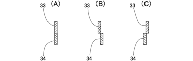
- the subject sees the first optotype image 33 and the second optotype image 34 overlapping each other in the aperture arrangement direction.
- the first optotype section 21 and the second optotype section 22, each having a rectangular shape are lined up in a straight line on the light emitting device 20 side, as shown in FIG.
- the optotype image 33 and the second optotype image 34 appear lined up in a straight line.
- the refractive power of the eye 25 is greater than the appropriate refractive power of the eye, the first light L1 passing through the first aperture 11 and the second light L2 passing through the second aperture 12 intersect before reaching the retina 27.
- the refractive power of the eye 25 is smaller than the appropriate refractive power of the eye, the first light L1 that has passed through the first aperture 11 and the second light L2 that has passed through the second aperture 12 are 27 and without intersecting before reaching the retina 27 (the position where the first light L1 and the second light L2 intersect is behind the retina 27 ). Therefore, in these cases, the subject sees the first optotype image 33 and the second optotype image 34 shifted in the aperture arrangement direction.
- FIG. 4(B) shows an example of the appearance when the refractive power of the eye 25 is larger than the appropriate value
- FIG. 4(C) shows an example of the appearance when the refractive power of the eye 25 is smaller than the appropriate value. represents.
- the first optotype image 33 and the second optotype image 34 Based on the appearance of the first optotype image 33 and the second optotype image 34, information on the refractive characteristics of the eye 25 can be obtained. However, it is difficult for the subject to quantitatively identify the shift between the two images and derive the refractive characteristics. Therefore, while changing the positional relationship between the first optotype section 21 and the second optotype section 22 along the aperture arrangement direction on the light emitting device 20 side, the first optotype image 33 and the second optotype image 34 are The first optotype part 21 and the second optotype part 22 are brought into a matching state in which they appear to overlap in the arrangement direction (the first optotype image 33 and the second optotype image 34 appear lined up in a straight line), and the first optotype part 21 and the second optotype part 22 in the matching state are The refractive power of the eye 25 is calculated from the positional relationship (the amount of shift and the direction of shift).
- the processing unit 2 constituting the refractive property measuring device 1 is composed of a computer or the like, and controls the position change of the first optotype section 21 and the second optotype section 22 along the aperture arrangement direction.
- the positions of the first optotype section 21 and the second optotype section 22 are made to change in accordance with an input operation by a subject or a measurer on an input device such as a keyboard or a touch panel.
- the processing unit 2 acquires distance information between the emission surface of the light emission device 20 and the measurement disk 10 from a distance sensor or the like.
- the processing unit 2 then processes the first optotype section 21 and the second optotype along the aperture arrangement direction when the first optotype image 33 and the second optotype image 34 are in the above-mentioned matching state on the retina 27.
- the refractive power of the eye 25 is calculated based on the amount of positional deviation of the portion 22.
- the formula described in the aforementioned Patent Document 1 Japanese Unexamined Patent Publication No. 2020-103743 can be used.
- the refractive power of the eye 25 can be measured with high accuracy simply by having the subject identify the matching state of the first optotype image 33 and the second optotype image 34. Since there is no need for the light emitting device 20 to perform complex light emission control or for the subject or the measurer to memorize the amount of deviation between the first optotype image 33 and the second optotype image 34, the refractive property measuring device 1 is easy to use. This simplifies the structure and control, and also reduces the effort required for measurement.
- the aperture arrangement directions of the first aperture 11 and the second aperture 12 are set to three or more directions: horizontal direction, vertical direction, and an intermediate direction between the horizontal direction and the vertical direction, and measurements are performed in each direction. is desirable.
- the first aperture 11 and the second aperture 12 have selective transmittance of light, so that only the shape corresponding to the first optotype 21 is observed through the first aperture 11, and the second aperture 12 through which only the shape corresponding to the second optotype section 22 is observed.
- the first optotype image 33 and the second optotype image 34 appear on the retina 27 at the same time, and the subject can check whether there is a positional shift between the first optotype image 33 and the second optotype image 34. It becomes easier to judge accurately.
- the first aperture 11 is provided with a first optical element 13, and the second aperture 12 is provided with a second optical element 14.
- the first optical element 13 and the second optical element 14 are optical filters that transmit light in different wavelength bands within the wavelength range of visible light.
- the refractive characteristic measuring device 1 that performs a subjective test
- a subject sees the first visual field area 30, second visual field area 31, overlapping area 32, first visual target image 33, and second visual target image 34 shown in FIG.
- the present invention relates to the color of light emitted by each part of the light emitting device 20 and the spectral characteristics at the first aperture 11 (first optical element 13) and second aperture 12 (second optical element 14) of the measurement disk 10. This was done based on the finding that visibility during observation by a subject can be significantly improved by setting the values to a predetermined relationship, and the details thereof will be explained below.
- FIG. 7, and FIG. 9 show the case where two optotype images match in the aperture arrangement direction, but this is just an example, and depending on the refractive characteristics of the eye 25, As shown in FIG. 4(B) and FIG. 4(C), the two optotype images may appear shifted in the aperture arrangement direction.
- the first light emitted from the first optotype section 21 of the light emitting device 20 Let L1 be a green light, and the second light L2 emitted from the second optotype section 22 be a red light.
- the background portion 23 of the light emitting device 20 is black. That is, in the comparative example, the light emitting device 20 includes a first optotype section 21 that emits green light, a second optotype section 22 that emits red light, and a black background section 23 (see FIG. (See “Comparative Examples” in 1).
- the first optical element 13 an optical filter is used that transmits green light and blocks red light.
- an optical filter is used that transmits red light and blocks green light. That is, in the comparative example, the wavelength band of the light transmitted by the first optical element 13 and the wavelength band of the first light L1 (green light) emitted from the first optotype section 21 are approximately the same, and the wavelength band of the light transmitted by the first optical element 13 is approximately the same. The wavelength band of the light transmitted by the element 14 and the wavelength band of the second light L2 (red light) emitted from the second optotype section 22 are substantially the same.
- the first light L1 which is green light
- the second light L2 which is red light
- the first aperture 11 passes through only the retina 27 of the eye 25.
- the retina 27 of the eye 25 reaches the retina 27 of the eye 25 through only the second aperture 12. Since the background part 23 is black, only the information of the first optotype part 21 passes through the first aperture 11, and only the information of the second optotype part 22 passes through the second opening 12.
- the visual field area and how the image is viewed by the subject in this case will be explained with reference to FIG.
- the substantially circular first viewing area 30GD corresponding to the first aperture 11 is obtained by observing the black background part 23 through the first optical element 13 that transmits green light, and the black background part 23 appears dark green (lower in brightness) due to the influence of ambient light. It looks like a low green color.
- the approximately circular second viewing area 31RD corresponding to the second aperture 12 is obtained by observing the black background portion 23 through the second optical element 14 that transmits red light, and the black background portion 23 appears dark red (lower in brightness) due to the influence of ambient light. It looks like a low red color.
- the overlapping region 32YD appears dark yellow (yellow with low brightness) due to the combination (additive color mixture) of the dark green of the first viewing region 30GD and the dark red of the second viewing region 31RD.
- the green light emitted by the first optotype section 21 is prevented from passing through the second aperture 12 by the second optical element 14, and is transmitted only through the first aperture 11 provided with the first optical element 13, and is transmitted through the overlapping area 32. It can be seen as a green first target image 33G above.
- the red light emitted from the second optotype section 22 is prevented from passing through the first aperture 11 by the first optical element 13, and is transmitted only through the second aperture 12 provided with the second optical element 14, and is transmitted through the overlapping area 32. It appears above as a red second optotype image 34R.
- the first visual field 30GD and the second visual field 31RD appear to overlap each other equally, as shown in FIG.
- the first optotype image 33G and the second optotype image 34R are located on the overlapping region 32YD.
- first visual field 30GD and the second visual field 31RD are dark green and dark red, respectively, against the black background part 23, there is a problem that each visual field is dark and difficult for the subject to distinguish. .
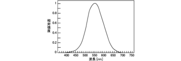
- Figure 6 shows the relative luminous efficiency of visible light.
- green light as an example, light in the wavelength band around 530nm to 540nm
- red light light in the wavelength band around 610nm to 640nm, for example
- the second visual field 31RD tends to be particularly difficult for the subject to see.
- the two lights entering the subject's eyes will be green light. It is possible to perform a refraction test even without red light.
- the first optotype section 21 may emit blue light (for example, light in a wavelength band around 450 nm to 465 nm), and the first optical element 13 may be an optical filter that passes the blue light.
- blue light has a lower relative luminous efficiency than green light, and has the same problem as red light in that it tends to make it difficult to see the viewing area seen through the first aperture 11. .
- the present inventor did not make the background part 23 of the light emitting device 20 black, and by emitting white light from the background part 23, the respective viewing areas corresponding to the first aperture 11 and the second aperture 12 were We focused on increasing the brightness and making it easier to identify.
- the visual field area and how the image is viewed by the subject when the background section 23 is changed to emit white light in the comparative example described above will be described with reference to FIG. 7.
- the substantially circular first viewing area 30GL corresponding to the first aperture 11 is formed by observing the white light emitted from the background part 23 through the first optical element 13 that transmits green light. It appears bright green (highly bright green).
- a substantially circular second viewing area 31RL corresponding to the second aperture 12 is formed by observing the white light emitted from the background part 23 through the second optical element 14 that transmits red light. red).
- the overlapping area 32YL appears bright yellow (yellow with high brightness) due to the combination (additive color mixture) of the bright green of the first viewing area 30GL and the bright red of the second viewing area 31RL. Therefore, compared to the case where the background part 23 is black (FIG. 5), it becomes easier for the subject to identify the first visual field area 30GL, the second visual field area 31RL, and the overlapping area 32YL.
- What passes through the second aperture 12 equipped with the second optical element 14 is not only the second light L2 (red light) emitted from the second optotype section 22 but also the white light emitted from the background section 23. Of these, components in a predetermined wavelength band near red are also included. Then, due to the refraction error between the light from the second optotype section 22 and the light from the background section 23, the corresponding part of the second optotype section 22 is not a single color of red, but a two-color mixture of parts of different colors. There is a possibility that the second optotype image 34X, which is a superimposed image, may be seen.
- the first optotype image 33X and the second optotype image 34X each of which appears as a double image, makes it difficult for the subject to grasp the positional relationship in the aperture arrangement direction.
- the background section 23 If only the change is made to emit white light, each viewing area (30GL, 31RL) corresponding to the first aperture 11 and second aperture 12 becomes easier to see, while the first optotype section 21 and the second optotype section There is a possibility that it becomes difficult to identify the positional relationship between the first optotype image 33X and the second optotype image 34X corresponding to each of 22.
- the inventor of the present invention determined that the color of the light emitted from the first optotype section 21 and the second optotype section 22 in the light emitting device 20 is changed to the light in the first wavelength band that is transmitted by the first optical element 13. It has been found that the above problem can be solved by using a complementary color to the color of the second optical element 14 and a complementary color to the color of the light in the second wavelength band transmitted by the second optical element 14.
- the first light L1 emitted by the first optotype section 21 is magenta light, which is the complementary color of the green light (light in the first wavelength band) transmitted by the first optical element 13. And so.
- the magenta color of the first light L1 is a color obtained by subtracting the green light (first wavelength band) component from white light.
- the second light L2 emitted by the second optotype section 22 was cyan light, which is a complementary color to the red light (light in the second wavelength band) transmitted by the second optical element 14.
- the cyan color of the second light L2 is a color obtained by subtracting the red light (second wavelength band) component from white light.
- the light emitting device 20 includes the first optotype section 21 that emits magenta light as the first light L1, and the first optotype section 21 that emits magenta light as the first light L1, and the first optotype section 21 that emits magenta light as the first light L1. It includes a second optotype section 22 that emits cyan light and a background section 23 that emits white light (see “this embodiment" in FIG. 1).
- the background part 23 emits white light
- the first optotype part 21 emits magenta first light L1
- the first optical element 13 transmits only the wavelength band of green light.
- This figure shows how the first viewing area 30GG corresponding to the first aperture 11 appears in the case of an optical filter that allows When observed only from the field of view of the first aperture 11 with the second aperture 12 closed, etc., it appears as shown in FIG. 8(A).
- the background part 23 that emits white light is observed through the first optical element 13, similar to the first viewing area 30GL in FIG. It appears bright green (green with high brightness) due to the green component of white light. Since magenta color is white excluding the green component (complementary color to green), when the first optotype section 21 emits the magenta first light L1, the transmitted color of the first optical element 13 The figure presented by the first optotype section 21 with respect to (green) becomes a shadow (black due to subtraction of complementary colors). As a result, the area corresponding to the first optotype section 21 in the first viewing area 30GG becomes a first shadow section 35 in which the shape of the first optotype section 21 is not colored.
- the background part 23 emits white light
- the second optotype part 22 emits cyan-colored second light L2
- the second optical element 14 transmits only the wavelength band of red light.
- This figure alone shows how the second viewing area 31RR corresponding to the second aperture 12 appears when the optical filter is an optical filter. When observed only through the field of view of the second aperture 12 with the first aperture 11 closed, etc., it appears as shown in FIG. 8(B).
- the background portion 23 that emits white light is observed through the second optical element 14, similarly to the second viewing area 31RL in FIG. It appears bright red (highly bright red) due to the red component of white light. Since cyan color is white with the red component removed (complementary color to red), when the second optotype section 22 emits the second cyan light L2, the transmitted color of the second optical element 14 The figure presented by the second optotype section 22 for (red) becomes a shadow (black due to subtraction of complementary colors). As a result, the area corresponding to the second optotype section 22 in the second visual field region 31RR becomes a second shadow section 36 in which the shape of the second optotype section 22 is not colored.
- the first optotype section 21 that emits the magenta first light L1 is viewed through the field of view of the second aperture 12, the red color in the white background in the background section 23 is reduced due to the action of the second optical element 14. Since the component and the magenta color cannot be distinguished, the first optotype section 21 is buried in the background section 23, and the subject cannot recognize the shape of the first optotype section 21.
- the action of the first optical element 13 causes the green color in the white background in the background section 23 to be Since the component and the cyan color cannot be distinguished, the second optotype section 22 is buried in the background section 23, and the subject cannot recognize the shape of the second optotype section 22.
- the shape corresponding to the first optotype section 21 is observed as the first shadow section 35 only in the field of view of the first aperture 11 (first viewing area 30GG). Further, the shape corresponding to the second optotype section 22 is observed as a second shadow section 36 only in the field of view of the second aperture 12 (second viewing region 31RR).
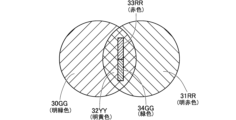
- the first viewing area 30GG in FIG. 8(A) and the second viewing area 31RR in FIG. 8(B) are combined to determine the viewing area and image appearance observed by the subject with the refractive property measuring device 1 of this embodiment. It is shown in FIG.
- the first visual field area 30GG and the second visual field area 31RR overlap in the central overlapping area 32YY.
- the first viewing area 30GG and the second viewing area 31RR appear bright and easy to identify by observing the white light emitted by the background part 23 through the first optical element 13 and the second optical element 14. ing. Further, similar to the overlapping region 32YL in FIG. 7 described above, the overlapping region 32YY in FIG. 9 appears bright yellow due to the combination (additive color mixture) of the bright green of the first visual field 30GG and the bright red of the second visual field 31RR. Therefore, it is easy for subjects to identify.
- a portion corresponding to the first shadow portion 35 is located in the overlapping region 32YL. Then, of the white light emitted by the background part 23, the part corresponding to the first shadow part 35 is the red component light (into the second viewing area 31RR) that has passed through the second aperture 12 (second optical element 14). ), it appears as a rectangular first optotype image 33RR. That is, the shape corresponding to the first optotype section 21 that emits the magenta first light L1 in the light emitting device 20 is observed as the red first optotype image 33RR.
- a portion corresponding to the second shadow portion 36 is located in the overlapping region 32YL. Then, of the white light emitted by the background part 23, the part corresponding to the second shadow part 36 is a part of the green component light (into the first viewing area 30GG) that has passed through the first aperture 11 (first optical element 13). ), it appears as a rectangular second target image 34GG. That is, the shape corresponding to the second optotype section 22 that emits cyan light in the light emitting device 20 is observed as the green second optotype image 34GG.
- the part corresponding to the first optotype part 21 becomes the first shadow part 35
- the part corresponding to the second optotype part 22 becomes the second shadow part 36.
- the first viewing area 30GG, the second viewing area 31RR, the overlapping area 32YY, the first optotype image 33RR, and the second optotype image 34GG shown in FIG. 9 all have high brightness and are easy to distinguish between colors. This improves visibility for the subject. More specifically, since the first visual field area 30GG, the second visual field area 31RR, and the overlapping area 32YY can be clearly identified, the first visual target image 33RR and the second visual target image 34GG are placed on the overlapping area 32YY in the measurement preparation stage. This makes it easier to adjust the position of the eye 25, making it easier to properly align the eye 25 with respect to the refractive characteristic measuring device 1.
- the first optotype image 33RR and the second optotype image 34GG are clearly visible as simple rectangular shapes of red and green, respectively, the first optotype image 33RR and the second optotype image in the aperture arrangement direction This makes it easier to judge the matching state of 34GG. As a result, the accuracy and efficiency of inspection can be improved.
- the first visual field area 30GG was expressed as bright green, the second visual field area 31RR as bright red, the first visual target image 33RR as red, and the second visual target image 34GG as green. This does not mean that the first visual field area 30GG and the second visual field area 31RR always appear brighter than the first visual target image 33RR and the second visual target image 34GG. This means that the first viewing area 30GG and the second viewing area 31RR have better visibility compared to the dark green of the first viewing area 30GD and the dark red of the second viewing area 30RD in the comparative example (FIG. 5). , bright green, and bright red.
- the first optotype image 33RR is an image in which the red component included in the white light of the background portion 23 is superimposed on the first shadow portion 35, it can be easily identified and clearly observed on the overlapping region 32YY.
- the second optotype image 34GG is an image in which the green component included in the white light of the background portion 23 is superimposed on the second shadow portion 36, it can be easily identified and clearly observed on the overlapping region 32YY. Therefore, high visibility can be obtained not only for the first visual field area 30GG and the second visual field area 31RR but also for the first visual target image 33RR and the second visual target image 34GG.
- the respective figures of the first optotype section 21 and the second optotype section 22 appear to be in different colors. For example, if the subject's eyes 25 are not in an appropriate position with respect to the measurement disk 10, the first shadow part 35 and the second shadow part 36 are not colored, and the first target image 33RR is red and the first target image 33RR is green. may not be visible as the second optotype image 34GG.
- whether or not the subject's eyes 25 are in an appropriate position can be determined based on the appearance of the positional relationship between the first visual field area 30GG, the second visual field area 31RR, and the overlapping area 32YY. The determination can also be made based on the appearance of the color of the portion corresponding to the second optotype section 22.
- the above effect is that the first aperture 11 (first optical element 13) and the second aperture 12 (second optical element 14) transmit light in the green wavelength band and light in the red wavelength band, respectively, and these two colors
- the first optotype section 21 and the second optotype section 22 emit magenta light and cyan light, which are complementary colors, and the background section 23 emits white light. Since it is characterized by the spectral characteristics imparted to the first optical element 13 and the second optical element 14 and the color setting of the light emitted from each region of the exit surface of the light exit device 20, It is superior in that it does not require complicated structures or controls and can be realized at low cost.
- green has a high relative luminous efficiency, so by using green as the color of the first viewing area 30GG and the second optotype image 34GG, the ease of identifying these parts is improved. Further, by using red as the color of the second visual field region 31RR and the first optotype image 33RR, it becomes easier to visually distinguish them from the first visual field region 30GG and the second optotype image 34GG, which are green.
- the light emitted from the background portion 23 of the light emitting device 20 be white light obtained by combining the following color components a1, a2, and a3.
- a1 Blue component with maximum intensity in the wavelength range of 440 mm to 475 nm.
- a2 Green component with maximum intensity in the wavelength range of 520 mm to 550 nm.
- a3 Red component with maximum intensity in the wavelength range of 600 mm to 650 nm.
- the first light L1 emitted from the first optotype section 21 of the light emitting device 20 is magenta light obtained by combining the color components a1 and a3 below.
- a1 Blue component with maximum intensity in the wavelength range of 440 mm to 475 nm.
- a3 Red component with maximum intensity in the wavelength range of 600 mm to 650 nm.
- the second light L2 emitted from the second optotype section 22 of the light emitting device 20 is cyan light obtained by combining the color components a1 and a2 below.
- a1 Blue component with maximum intensity in the wavelength range of 440 mm to 475 nm.
- a2 Green component with maximum intensity in the wavelength range of 520 mm to 550 nm.
- the center wavelength of the blue component is in the range of 450 nm to 465 nm
- the center wavelength of the green component is in the range of 530 nm to 540 nm
- the center wavelength of the red component is in the range of 610 nm to 640 nm.
- the values of a1, a2, and a3 are set with a margin of about ⁇ 10 nm in each range.
- the first optical element 13 provided in the first opening 11 suppresses the transmission of the first light L1 (magenta color) and transmits the green component having the maximum intensity in the wavelength range of 520 mm to 550 nm among the white light of the background portion 23. It is an optical filter and preferably satisfies the following conditions (1) and (2).
- T B1 /T G1 ⁇ 1/10 (2)
- T R1 /T G1 ⁇ 1/10 T G1 Transmittance at wavelength ⁇ G2 corresponding to the maximum intensity of the green component (520 nm to 550 nm) of the second light L2 (cyan color).
- T B1 Transmittance at wavelength ⁇ B1 corresponding to the maximum intensity of the blue component (440 nm to 475 nm) of the first light L1 (magenta color).
- T R1 Transmittance at the wavelength ⁇ R1 corresponding to the maximum intensity of the red component (600 nm to 650 nm) of the first light L1 (magenta color).
- condition (1) the effect of suppressing the transmission of the blue component of the magenta first light L1 and reducing crosstalk can be obtained.
- condition (2) the effect of suppressing transmission of the red component of the first light L1, which is magenta, and reducing crosstalk can be obtained. Therefore, by using the first optical element 13 that satisfies conditions (1) and (2), it is possible to sufficiently suppress the transmission of the first light L1 and to sufficiently transmit the green component of the second light L2. can.
- the second optical element 14 provided in the second opening 12 suppresses the transmission of the second light L2 (cyan color) and transmits the red component having the maximum intensity in the wavelength range of 600 mm to 650 nm among the white light of the background portion 23. It is an optical filter and preferably satisfies the following conditions (3) and (4). (3) T B2 / T R2 ⁇ 1/10 (4) T G2 /T R2 ⁇ 1/10 T R2 : Transmittance at the wavelength ⁇ R1 corresponding to the maximum intensity of the red component (600 nm to 650 nm) of the first light L1 (magenta color).
- T B2 Transmittance at wavelength ⁇ B2 corresponding to the maximum intensity of the blue component (440 nm to 475 nm) of the second light L2 (cyan color).
- T G2 Transmittance at wavelength ⁇ G2 corresponding to the maximum intensity of the green component (520 nm to 550 nm) of the second light L2 (cyan color).
- condition (3) the effect of suppressing the transmission of the blue component of the cyan second light L2 and reducing crosstalk can be obtained.
- condition (4) the effect of suppressing transmission of the green component of the cyan second light L2 and reducing crosstalk can be obtained. Therefore, by using the second optical element 14 that satisfies conditions (3) and (4), it is possible to sufficiently suppress transmission of the second light L2 and sufficiently transmit the red component of the first light L1. can.
- the first optical element 13 of Example 1 and Example 3 both satisfy condition (1) and condition (2). Further, the second optical element 14 of Example 2 and Example 4 both satisfy condition (3) and condition (4).
- Bandpass filters and longpass filters having the spectral characteristics illustrated in each embodiment are widely used for color correction and color separation in optical equipment, and are highly available.
- the light in the first wavelength band transmitted by the first optical element 13 is green light
- the light in the second wavelength band transmitted by the second optical element 14 is red light
- the optotype section 21 emits first light L1 of magenta color (complementary color of green)
- the second optotype section 22 emits second light L2 of cyan color (complementary color of red).
- the subject observes two visual field areas (first visual field area 30GG, second visual field area 31RR) and two visual target images (first visual target image 33RR,
- the two optotype images 34GG) are green, which has a high relative luminous efficiency, and red, which is close to the psychological complementary color relationship with green, so that visibility for the subject can be improved.
- the first optical element 13 and the second optical element 14 transmit light in the wavelength band, the first light L1 emitted by the first optotype section 21, and the second light L1 emitted from the second optotype section 22.
- the light L2 it is also possible to change the color setting from the above embodiment.
- the first optical element provided in the first aperture transmits light in the first wavelength band and blocks the transmission of light in the second wavelength band
- the second optical element provided in the second aperture transmits light in the first wavelength band.
- the first light emitted from the first optotype is configured to transmit the light in the second wavelength band and block the transmission of the light in the first wavelength band.
- the colors are complementary, and the second light emitted from the second optotype is a complementary color to the light in the second wavelength band.
- the settings for each color are determined based on factors such as visibility from the test subject and productivity of the light emitting section. It is possible to select as appropriate.
- the detailed configuration of the refractive property measuring device may be different from the refractive property measuring device 1 of the above-described embodiment.
- the shapes of the first optotype section 21 and the second optotype section 22 may be other than rectangular.
Landscapes
- Health & Medical Sciences (AREA)
- Life Sciences & Earth Sciences (AREA)
- Physics & Mathematics (AREA)
- General Physics & Mathematics (AREA)
- Analytical Chemistry (AREA)
- Chemical & Material Sciences (AREA)
- Medical Informatics (AREA)
- Heart & Thoracic Surgery (AREA)
- Biomedical Technology (AREA)
- Molecular Biology (AREA)
- Surgery (AREA)
- Animal Behavior & Ethology (AREA)
- General Health & Medical Sciences (AREA)
- Public Health (AREA)
- Veterinary Medicine (AREA)
- Engineering & Computer Science (AREA)
- Ophthalmology & Optometry (AREA)
- Biophysics (AREA)
- Eye Examination Apparatus (AREA)
Abstract
Description
(1)TB1/TG1<1/10
(2)TR1/TG1<1/10
TG1:前記第2の光のうち前記緑色成分の最大強度に相当する波長における前記第1光学素子の透過率。
TB1:前記第1の光のうち前記青色成分の最大強度に相当する波長における前記第1光学素子の透過率。
TR1:前記第1の光のうち前記赤色成分の最大強度に相当する波長における前記第1光学素子の透過率。
(3)TB2/TR2<1/10
(4)TG2/TR2<1/10
TR2:前記第1の光のうち前記赤色成分の最大強度に相当する波長における前記第2光学素子の透過率。
TB2:前記第2の光のうち前記青色成分の最大強度に相当する波長における前記第2光学素子の透過率。
TG2:前記第2の光のうち前記緑色成分の最大強度に相当する波長における前記第2光学素子の透過率。
a1:波長440mm~475nmに最大強度を持つ青色成分。
a2:波長520mm~550nmに最大強度を持つ緑色成分。
a3:波長600mm~650nmに最大強度を持つ赤色成分。
a1:波長440mm~475nmに最大強度を持つ青色成分。
a3:波長600mm~650nmに最大強度を持つ赤色成分。
a1:波長440mm~475nmに最大強度を持つ青色成分。
a2:波長520mm~550nmに最大強度を持つ緑色成分。
(1)TB1/TG1<1/10
(2)TR1/TG1<1/10
TG1:第2の光L2(シアン色)のうち緑色成分(520nm~550nm)の最大強度に相当する波長λG2における透過率。
TB1:第1の光L1(マゼンタ色)のうち青色成分(440nm~475nm)の最大強度に相当する波長λB1における透過率。
TR1:第1の光L1(マゼンタ色)のうち赤色成分(600nm~650nm)の最大強度に相当する波長λR1における透過率。
(3)TB2/TR2<1/10
(4)TG2/TR2<1/10
TR2:第1の光L1(マゼンタ色)のうち赤色成分(600nm~650nm)の最大強度に相当する波長λR1における透過率。
TB2:第2の光L2(シアン色)のうち青色成分(440nm~475nm)の最大強度に相当する波長λB2における透過率。
TG2:第2の光L2(シアン色)のうち緑色成分(520nm~550nm)の最大強度に相当する波長λG2における透過率。
光射出装置20(LEDバックライト使用の液晶ディスプレイ)
λB1=450nm
λG2=540nm
λR1=610nm
第1光学素子13(波長530nm付近に透過率のピークを有するバンドパスフィルタ)
TB1=0.00
TG1=0.54
TR1=0.03
TB1/TG1=0.00
TR1/TG1≒0.06
光射出装置20(LEDバックライト使用の液晶ディスプレイ)
λB2=450nm
λG2=540nm
λR1=610nm
第2光学素子14(波長600nm付近が透過限界波長であるロングパスフィルタ)
TB2=0.00
TG2=0.00
TR2=0.65
TB2/TG2=0.00
TR2/TG2=0.00
光射出装置20(レーザーバックライト使用の液晶ディスプレイ)
λB1=450nm
λG2=540nm
λR1=610nm
第1光学素子13(波長535nm付近に透過率のピークを有するバンドパスフィルタ)
TB1=0.00
TG1=0.63
TR1=0.03
TB1/TG1=0.00
TR1/TG1≒0.05
光射出装置20(レーザーバックライト使用の液晶ディスプレイ)
λB2=465nm
λG2=530nm
λR1=639nm
第2光学素子14(波長575nm付近が透過限界波長であるロングパスフィルタ)
TB2=0.00
TG2=0.00
TR2=0.88
TB2/TG2=0.00
TR2/TG2=0.00
Claims (6)
- 眼の屈折特性を測定する屈折特性測定装置であって、
光射出部と、
前記光射出部と眼との間に位置し、前記光射出部が発した光を絞って通過させる第1開口及び第2開口を有する開口部材と、
前記第1開口に設けられ、第1の波長帯域の光を透過させ、第2の波長帯域の光の透過を阻止する第1光学素子と、
前記第2開口に設けられ、前記第2の波長帯域の光を透過させ、前記第1の波長帯域の光の透過を阻止する第2光学素子と、を備え、
前記光射出部は、白色光を射出する背景部と、前記第1の波長帯域の光に対する補色となる第1の光を射出する第1視標部と、前記第2の波長帯域の光に対する補色となる第2の光を射出する第2視標部と、を備えることを特徴とする屈折特性測定装置。 - 前記第1の波長帯域の光は緑色光、前記第2の波長帯域の光は赤色光であり、前記第1視標部が射出する前記第1の光はマゼンタ色の光であり、前記第2視標部が射出する前記第2の光はシアン色の光であることを特徴とする請求項1に記載の屈折特性測定装置。
- 前記背景部は、波長帯域440nm~475nmに最大強度がある青色成分の光と、波長帯域520nm~550nmに最大強度がある緑色成分の光と、波長帯域600nm~650nmに最大強度がある赤色成分の光との合成で前記白色光を発し、
前記第1視標部は、前記青色成分の光と前記赤色成分の光との合成で前記第1の光を発し、
前記第2視標部は、前記青色成分の光と前記緑色成分の光との合成で前記第2の光を発することを特徴とする請求項2に記載の屈折特性測定装置。 - 前記第1光学素子は、下記条件(1)及び(2)を満たすことを特徴とする請求項3に記載の屈折特性測定装置。
(1)TB1/TG1<1/10
(2)TR1/TG1<1/10
TG1:前記第2の光のうち前記緑色成分の最大強度に相当する波長における前記第1光学素子の透過率。
TB1:前記第1の光のうち前記青色成分の最大強度に相当する波長における前記第1光学素子の透過率。
TR1:前記第1の光のうち前記赤色成分の最大強度に相当する波長における前記第1光学素子の透過率。 - 前記第2光学素子は、下記条件(3)及び(4)を満たすことを特徴とする請求項3に記載の屈折特性測定装置。
(3)TB2/TR2<1/10
(4)TG2/TR2<1/10
TR2:前記第1の光のうち前記赤色成分の最大強度に相当する波長における前記第2光学素子の透過率。
TB2:前記第2の光のうち前記青色成分の最大強度に相当する波長における前記第2光学素子の透過率。
TG2:前記第2の光のうち前記緑色成分の最大強度に相当する波長における前記第2光学素子の透過率。 - 前記第1開口及び前記第2開口は直径が同じ円形であり、
前記第1開口を通して観察される第1視野領域と前記第2開口を通して観察される第2視野領域とが重なる重複領域に、前記第1視標部に対応する形状の第1視標像と、前記第2視標部に対応する形状の第2視標像とが観察されることを特徴とする請求項1から請求項5のいずれかに記載の屈折特性測定装置。
Priority Applications (2)
| Application Number | Priority Date | Filing Date | Title |
|---|---|---|---|
| US18/837,703 US20250216289A1 (en) | 2022-03-09 | 2023-03-06 | Refractive characteristic measurement device |
| EP23766782.9A EP4491097A4 (en) | 2022-03-09 | 2023-03-06 | REFRACTIVE CHARACTERISTICS MEASUREMENT DEVICE |
Applications Claiming Priority (2)
| Application Number | Priority Date | Filing Date | Title |
|---|---|---|---|
| JP2022035759A JP7610544B2 (ja) | 2022-03-09 | 2022-03-09 | 屈折特性測定装置 |
| JP2022-035759 | 2022-03-09 |
Publications (1)
| Publication Number | Publication Date |
|---|---|
| WO2023171606A1 true WO2023171606A1 (ja) | 2023-09-14 |
Family
ID=87935028
Family Applications (1)
| Application Number | Title | Priority Date | Filing Date |
|---|---|---|---|
| PCT/JP2023/008295 Ceased WO2023171606A1 (ja) | 2022-03-09 | 2023-03-06 | 屈折特性測定装置 |
Country Status (4)
| Country | Link |
|---|---|
| US (1) | US20250216289A1 (ja) |
| EP (1) | EP4491097A4 (ja) |
| JP (1) | JP7610544B2 (ja) |
| WO (1) | WO2023171606A1 (ja) |
Citations (3)
| Publication number | Priority date | Publication date | Assignee | Title |
|---|---|---|---|---|
| US20020140903A1 (en) * | 2001-03-28 | 2002-10-03 | Ras Holding Corp | System and method for providing an improved test for determining the resolving power of the eye |
| JP2020103743A (ja) | 2018-12-28 | 2020-07-09 | ホヤ レンズ タイランド リミテッドHOYA Lens Thailand Ltd | 屈折特性測定装置、測定治具、及び屈折特性測定方法 |
| JP2022035759A (ja) | 2020-08-21 | 2022-03-04 | キヤノンファインテックニスカ株式会社 | 記録装置 |
Family Cites Families (2)
| Publication number | Priority date | Publication date | Assignee | Title |
|---|---|---|---|---|
| CN107636532A (zh) * | 2015-06-03 | 2018-01-26 | 奥林巴斯株式会社 | 摄像装置、内窥镜装置以及摄像方法 |
| JP2021175048A (ja) * | 2020-04-22 | 2021-11-01 | ソニーセミコンダクタソリューションズ株式会社 | 電子機器 |
-
2022
- 2022-03-09 JP JP2022035759A patent/JP7610544B2/ja active Active
-
2023
- 2023-03-06 WO PCT/JP2023/008295 patent/WO2023171606A1/ja not_active Ceased
- 2023-03-06 US US18/837,703 patent/US20250216289A1/en active Pending
- 2023-03-06 EP EP23766782.9A patent/EP4491097A4/en active Pending
Patent Citations (3)
| Publication number | Priority date | Publication date | Assignee | Title |
|---|---|---|---|---|
| US20020140903A1 (en) * | 2001-03-28 | 2002-10-03 | Ras Holding Corp | System and method for providing an improved test for determining the resolving power of the eye |
| JP2020103743A (ja) | 2018-12-28 | 2020-07-09 | ホヤ レンズ タイランド リミテッドHOYA Lens Thailand Ltd | 屈折特性測定装置、測定治具、及び屈折特性測定方法 |
| JP2022035759A (ja) | 2020-08-21 | 2022-03-04 | キヤノンファインテックニスカ株式会社 | 記録装置 |
Non-Patent Citations (1)
| Title |
|---|
| See also references of EP4491097A4 |
Also Published As
| Publication number | Publication date |
|---|---|
| US20250216289A1 (en) | 2025-07-03 |
| JP2023131184A (ja) | 2023-09-22 |
| EP4491097A1 (en) | 2025-01-15 |
| EP4491097A4 (en) | 2026-02-25 |
| JP7610544B2 (ja) | 2025-01-08 |
Similar Documents
| Publication | Publication Date | Title |
|---|---|---|
| KR100679147B1 (ko) | 검안장치 및 검안차트 | |
| TWI849287B (zh) | 視覺特性之檢查方法、光學濾鏡之特性決定方法、光學濾鏡、視覺特性檢查用之光學元件組、及視覺特性之檢查用圖像 | |
| JP5378474B2 (ja) | 視力検査装置 | |
| JPWO2021166996A5 (ja) | ||
| WO2014101277A1 (zh) | 一种测量视觉阈值的装置与方法 | |
| JP6769605B2 (ja) | レンズメータ | |
| WO2023171606A1 (ja) | 屈折特性測定装置 | |
| JP5931387B2 (ja) | 色覚検査装置及び色覚測定方法 | |
| JP3210575U (ja) | コントラストチャート | |
| JPH0240328B2 (ja) | ||
| US20210106218A1 (en) | Visual field test device | |
| JP7241579B2 (ja) | 視標呈示装置 | |
| JP5079347B2 (ja) | 視標呈示装置 | |
| Mutalib et al. | Red tinted contact lenses on Ishihara test error scores in color deficient subjects: a pilot study | |
| JPWO2016163338A1 (ja) | 光学素子の作製方法及び光学素子、並びに、色覚特性の検査プログラム、検査装置及び色覚検査画像セット | |
| JP2022034690A (ja) | 視力検査装置 | |
| SU1440488A1 (ru) | Колориметрическа приставка к фундус-камере | |
| Farnsworth | The effect of colored lenses upon color discrimination | |
| JP7198135B2 (ja) | 視標呈示装置 | |
| Walter et al. | Objective approach for measuring changes in color discrimination caused by transparent colored filter media | |
| RU2387363C1 (ru) | Способ исследования поверхности роговицы | |
| KR100965804B1 (ko) | 삼자극값을 이용한 광색채분석장치의 탐측기 | |
| KR20200018063A (ko) | 시력검사기구 | |
| KR100815609B1 (ko) | 색채측정장치용 등색함수필터 | |
| RU2164074C2 (ru) | Устройство для контроля остроты зрения |
Legal Events
| Date | Code | Title | Description |
|---|---|---|---|
| 121 | Ep: the epo has been informed by wipo that ep was designated in this application |
Ref document number: 23766782 Country of ref document: EP Kind code of ref document: A1 |
|
| WWE | Wipo information: entry into national phase |
Ref document number: 2023766782 Country of ref document: EP |
|
| NENP | Non-entry into the national phase |
Ref country code: DE |
|
| ENP | Entry into the national phase |
Ref document number: 2023766782 Country of ref document: EP Effective date: 20241009 |
|
| WWP | Wipo information: published in national office |
Ref document number: 18837703 Country of ref document: US |