WO2023171636A1 - 封止部材及び血液バッグセット - Google Patents
封止部材及び血液バッグセット Download PDFInfo
- Publication number
- WO2023171636A1 WO2023171636A1 PCT/JP2023/008443 JP2023008443W WO2023171636A1 WO 2023171636 A1 WO2023171636 A1 WO 2023171636A1 JP 2023008443 W JP2023008443 W JP 2023008443W WO 2023171636 A1 WO2023171636 A1 WO 2023171636A1
- Authority
- WO
- WIPO (PCT)
- Prior art keywords
- sealing member
- base
- breakable
- axial direction
- neck
- Prior art date
- Legal status (The legal status is an assumption and is not a legal conclusion. Google has not performed a legal analysis and makes no representation as to the accuracy of the status listed.)
- Ceased
Links
Images




Classifications
-
- A—HUMAN NECESSITIES
- A61—MEDICAL OR VETERINARY SCIENCE; HYGIENE
- A61J—CONTAINERS SPECIALLY ADAPTED FOR MEDICAL OR PHARMACEUTICAL PURPOSES; DEVICES OR METHODS SPECIALLY ADAPTED FOR BRINGING PHARMACEUTICAL PRODUCTS INTO PARTICULAR PHYSICAL OR ADMINISTERING FORMS; DEVICES FOR ADMINISTERING FOOD OR MEDICINES ORALLY; BABY COMFORTERS; DEVICES FOR RECEIVING SPITTLE
- A61J1/00—Containers specially adapted for medical or pharmaceutical purposes
- A61J1/05—Containers specially adapted for medical or pharmaceutical purposes for collecting, storing or administering blood, plasma or medical fluids ; Infusion or perfusion containers
- A61J1/10—Bag-type containers
- A61J1/12—Bag-type containers with means for holding samples of contents
-
- A—HUMAN NECESSITIES
- A61—MEDICAL OR VETERINARY SCIENCE; HYGIENE
- A61J—CONTAINERS SPECIALLY ADAPTED FOR MEDICAL OR PHARMACEUTICAL PURPOSES; DEVICES OR METHODS SPECIALLY ADAPTED FOR BRINGING PHARMACEUTICAL PRODUCTS INTO PARTICULAR PHYSICAL OR ADMINISTERING FORMS; DEVICES FOR ADMINISTERING FOOD OR MEDICINES ORALLY; BABY COMFORTERS; DEVICES FOR RECEIVING SPITTLE
- A61J1/00—Containers specially adapted for medical or pharmaceutical purposes
- A61J1/05—Containers specially adapted for medical or pharmaceutical purposes for collecting, storing or administering blood, plasma or medical fluids ; Infusion or perfusion containers
- A61J1/10—Bag-type containers
-
- A—HUMAN NECESSITIES
- A61—MEDICAL OR VETERINARY SCIENCE; HYGIENE
- A61J—CONTAINERS SPECIALLY ADAPTED FOR MEDICAL OR PHARMACEUTICAL PURPOSES; DEVICES OR METHODS SPECIALLY ADAPTED FOR BRINGING PHARMACEUTICAL PRODUCTS INTO PARTICULAR PHYSICAL OR ADMINISTERING FORMS; DEVICES FOR ADMINISTERING FOOD OR MEDICINES ORALLY; BABY COMFORTERS; DEVICES FOR RECEIVING SPITTLE
- A61J1/00—Containers specially adapted for medical or pharmaceutical purposes
- A61J1/14—Details; Accessories therefor
-
- A—HUMAN NECESSITIES
- A61—MEDICAL OR VETERINARY SCIENCE; HYGIENE
- A61M—DEVICES FOR INTRODUCING MEDIA INTO, OR ONTO, THE BODY; DEVICES FOR TRANSDUCING BODY MEDIA OR FOR TAKING MEDIA FROM THE BODY; DEVICES FOR PRODUCING OR ENDING SLEEP OR STUPOR
- A61M39/00—Tubes, tube connectors, tube couplings, valves, access sites or the like, specially adapted for medical use
- A61M39/22—Valves or arrangement of valves
- A61M39/221—Frangible or pierceable closures within tubing
-
- A—HUMAN NECESSITIES
- A61—MEDICAL OR VETERINARY SCIENCE; HYGIENE
- A61M—DEVICES FOR INTRODUCING MEDIA INTO, OR ONTO, THE BODY; DEVICES FOR TRANSDUCING BODY MEDIA OR FOR TAKING MEDIA FROM THE BODY; DEVICES FOR PRODUCING OR ENDING SLEEP OR STUPOR
- A61M39/00—Tubes, tube connectors, tube couplings, valves, access sites or the like, specially adapted for medical use
- A61M39/22—Valves or arrangement of valves
- A61M39/221—Frangible or pierceable closures within tubing
- A61M2039/222—Frangible or pierceable closures within tubing frangible within tubing or bags
Definitions
- the present invention relates to a sealing member and a blood bag set that openably seal a flow path of a medical tube.
- a sealing member is used to seal a medical tube so that it can be opened.
- the sealing member is a cap-shaped member fitted into the lumen of the medical tube, and seals the medical tube in an initial state.
- the sealing member has a breakable portion. When the sealing member is bent, the breakable portion breaks, and the sealing member opens the medical tube.
- Such a sealing member is used, for example, in a blood bag set (Japanese Patent Laid-Open No. 8-275986).
- the sealing member If the sealing member is insufficiently bent during the opening operation, a part of the breakable portion may become connected, resulting in an opening failure. Even if the opening is defective, the sealing member can allow liquid such as blood to flow. However, with conventional sealing members, there is a risk that when blood passes through a narrow broken portion that is poorly opened, it may damage red blood cells and cause hemolysis.
- the present invention aims to solve the above problems.
- One aspect of the following disclosure is to provide a base having an outer circumferential surface that abuts an inner surface of a medical tube, a base flow path extending in the axial direction through which a fluid passes, and the base flow path being open at a proximal end.
- a neck portion located at the distal end of the base portion where the outer diameter of the base portion is reduced; and a neck portion connected to the base portion via the neck portion and extending from the base portion toward the distal end side in the axial direction; a plug portion that closes the plug portion, and a breakable portion consisting of the thinnest wall thickness at the boundary between the proximal end of the plug portion and the neck portion, the breakable portion being When viewed from the tip side, it has a non-circular shape having a plurality of apices and a plurality of connecting parts formed between the apexes, and the distance between the base and the axis is inscribed in the plurality of connecting parts.
- the sealing member is larger than the radius of the circle, and the base portion bulges outward in the radial direction than the connecting portion.
- Another aspect includes the sealing member according to the above aspect, a blood bag containing whole blood or blood components, and a medical tube communicating with the blood bag, wherein the sealing member is connected to the medical tube.
- the blood bag set abuts the inner surface to openably close the medical tube.
- the sealing member and blood bag set according to the above aspect can reduce the occurrence of opening failures due to the breakable portion being more likely to break. Further, in the above-described sealing member and blood bag set, even if an opening failure occurs in the sealing member, hemolysis can be prevented because the flow path cross-sectional area of the fractured portion is large.
- FIG. 1 is a side view of a sealing member according to an embodiment.
- 2 is a six-sided view of the sealing member of FIG. 1.
- FIG. 3 is a longitudinal sectional view of the sealing member of FIG. 1.
- FIG. 4A is a perspective view of the sealing member of FIG. 1
- FIG. 4B is a diagram showing a broken portion of the sealing member of FIG. 1 after the plug portion is separated, viewed from the tip side in the axial direction.
- FIG. 5 is a diagram showing the distribution of stress generated in the breakable portion when the plug portion of the sealing member shown in FIG. 1 is bent.
- FIG. 6 is an explanatory diagram of a state where an opening failure has occurred in the sealing member of FIG. 1.
- FIG. 3 is a longitudinal sectional view of the sealing member of FIG. 1.
- FIG. 4A is a perspective view of the sealing member
- FIG. 7 is an explanatory diagram of a state in which an opening failure occurs in a sealing member according to a comparative example.
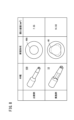
- FIG. 8 is a diagram showing a comparison of the cross-sectional shape and opening area of the breakable portion of the sealing member according to the comparative example and the sealing member of FIG. 1, respectively.
- FIG. 9 is a schematic diagram of a blood bag set using the sealing member of FIG. 1.
- FIG. 10A is a diagram showing a shape of a breakable portion according to a first modification of the embodiment
- FIG. 10B is a diagram showing a shape of a breakable portion according to a second modification of the embodiment.
- FIG. 11 is a sectional view showing the shape of the breakable portion according to Modification 3 of the embodiment.
- the sealing member 10 is used to seal the flow path 12a of the medical tube 12, as shown in FIG.
- the sealing member 10 is liquid-tightly fixed to the flow path 12a of the medical tube 12 in an initial state.
- the base portion 14 and the plug portion 16 are connected via the breakable portion 18, and the plug portion 16 seals the flow path 12a.
- the breakable portion 18 of the sealing member 10 breaks to open the flow path 12a.
- Such a sealing member 10 is used, for example, in a blood bag set 20 shown in FIG.
- the blood bag set 20 includes a blood collection needle 22, a first tube 24, a second tube 26, a third tube 28, a branch 30, a first blood bag 32, a sampling holder 34, and a blood bag 36. has.
- the blood collection needle 22 is connected to one end of the first tube 24.
- the other end of the first tube 24 is connected to a first port 30a of a branch section 30 branched into three directions.
- the second tube 26 is connected to the second port 30b (see FIG. 9) of the branch section 30, and the third tube 28 is connected to the third port 30c (see FIG. 9) of the branch section 30.
- the second tube 26 connects the branch part 30 and the first blood flow bag 32.
- the sampling holder 34 is connected downstream of the first blood flow bag 32 .
- the third tube 28 connects the branch portion 30 and the blood bag 36 (blood collection bag).
- the sealing member 10 of FIG. 1 is attached to the third tube 28 in the vicinity of the third port 30c of the branch portion 30. In the initial state, the sealing member 10 closes the third port 30c and the third tube 28.
- the blood collection needle 22 of the blood bag set 20 collects blood from a blood donor. Since the third port 30c of the branch portion 30 is closed by the sealing member 10, the collected blood flows into the second tube 26 through the second port 30b. Blood is stored in the initial blood flow bag 32.
- the sampling holder 34 is used to collect a portion of the collected blood into a sample tube or the like.
- the operation of collecting donor blood into the blood bag 36 is performed by closing the second tube 26 of the blood bag set 20 with the clamp 31 and opening the sealing member 10.
- the sealing member 10 is used, for example, to open and close the flow path of the blood bag set 20.
- the sealing member 10 has a base portion 14 and a plug portion 16.
- the base 14 has a cylindrical shape extending in the axial direction.
- the outer circumferential surface 14a of the base 14 is fixed to the channel 12a by liquid-tightly abutting the inner circumferential surface 12b of the channel 12a of the medical tube 12.
- the medical tube 12 is, for example, the third tube 28 described above.
- the base 14 of the sealing member 10 has a base channel 14b inside.
- the base channel 14b is surrounded by the outer circumferential surface 14a of the base 14 and the inner circumferential surface 14c that is concentric with the outer circumferential surface 14a.
- the base channel 14b extends in the axial direction.
- the base end of the base channel 14b opens at the base end of the base portion 14.
- the tip of the base channel 14b extends into the plug portion 16.
- the base 14 has a neck 38 at the tip.
- the neck portion 38 is a portion whose outer diameter is smaller than that of the base portion 14 and extends toward the tip.
- the neck portion 38 has an outer circumferential surface 38a formed of a conical surface.
- the plug portion 16 extends in the axial direction from the neck portion 38 toward the tip. In the initial state, the plug portion 16 is integrally connected to the base portion 14 via the neck portion 38. As shown in FIG. 3, the plug portion 16 has a solid portion. The solid portion of the plug portion 16 covers the distal end side of the base channel 14b, thereby closing the distal end of the base channel 14b. As shown in FIG. 1, the plug portion 16 has a smaller outer diameter than the base portion 14. Therefore, the plug portion 16 is separated from the inner circumferential surface 12b of the medical tube 12 when the sealing member 10 is fixed to the medical tube 12.
- the plug portion 16 has three ridge lines 40a that protrude outward in the radial direction from the central axis of the sealing member 10.
- the three ridgelines 40a of the plug portion 16 are arranged at an angle of 120° in the circumferential direction around the central axis.
- Each ridgeline 40a extends linearly in the axial direction.
- a top portion 40 of the breakable portion 18 is formed at the boundary between the ridgeline 40a and the neck portion 38.
- a relatively flat curved surface 41a is formed between one ridgeline 40a and another ridgeline 40a adjacent thereto.
- the curved surface 41a is a portion with a relatively small curvature, and connects two adjacent apexes 40 with a smooth surface.
- a connecting portion 41 of the breakable portion 18 is formed at the boundary between the curved surface 41a and the neck portion 38.
- the curved surface 41a of the plug portion 16 may have a concave portion 42a that is concavely curved toward the central axis of the sealing member 10, as shown in the drawing.
- the concave surface portion 42a includes a curved surface whose center of curvature is located outside the plug portion 16.
- a recess 42 of the breakable portion 18 is formed at the boundary between the concave surface portion 42a and the neck portion 38.
- the connecting portion 41 including the recess 42 becomes a portion where the breakable portion 18 is relatively easily broken by the force of bending the plug portion 16 .
- the breakable portions appear in three directions, so the user can break the breakable portion 18 without worrying about the orientation of the stopper portion 16.
- the breakable portion 18 is formed at the boundary between the proximal end of the plug portion 16 and the neck portion 38.
- the breakable portion 18 has a groove portion 44 formed along a line where the outer circumferential surface 16a of the plug portion 16 and the outer circumferential surface 38a of the neck portion 38 intersect.
- the groove portion 44 is the thinnest portion 45 that is the thinnest portion of the sealing member 10 .
- the groove portion 44 extends linearly, and extends in the circumferential direction along the outer circumferential surface 38a of the neck portion 38. As shown in FIGS.
- the groove portion 44 has a plurality of top portions 40 and a recess portion 42 (connection portion 41) located between the top portions 40 when viewed from the tip side in the axial direction, and It extends in a wavy manner. Further, as shown in FIG. 1, the groove portion 44 also meanders in the axial direction when viewed from the side. In this way, the groove portions 44 are distributed three-dimensionally, not along one plane.
- the groove portion 44 of the breakable portion 18 is thinner than the other portions of the sealing member 10. Therefore, the groove part 44 is easily broken by the opening operation of bending the plug part 16.
- the entire groove portion 44 is broken and the plug portion 16 is separated from the base portion 14.
- a broken portion 46 shown in FIG. 4B appears in the base 14 where the breakable portion 18 is broken.
- the groove portion 44 forms a broken portion 46 that waves in the circumferential direction when viewed from the tip side in the axial direction.
- the sealing member 10 of this embodiment operates as follows.
- the plug part 16 of the sealing member 10 is separated from the inner peripheral surface 12b of the medical tube 12, the plug part 16 can be bent.
- the breakable portion 18 breaks.
- the plug part 16 has a concave surface part 42a between the ridge lines 40a, which makes it easy for the user to input operating force.
- stress concentration portions 50 are generated at both ends of the recess 42 in the circumferential direction. These stress concentration portions 50 serve as starting points for fracture of the breakable portion 18 when a relatively weak bending force is input.
- the breakable portion 18 of the sealing member 10 is reliably broken even when a weak bending force is input. Thereby, the sealing member 10 can suppress the frequency of occurrence of opening defects.
- a three-dimensionally undulating broken portion 46A is formed in the sealing member 10.
- the gap between the neck portion 38 and the plug portion 16 along the fracture portion 46A becomes a fluid flow path.
- the three-dimensionally undulating broken portion 46A can form a relatively large flow path cross-sectional area. Therefore, according to the sealing member 10, even if a patency failure occurs, damage to red blood cells in the blood can be prevented, and the risk of hemolysis can be reduced.
- the sealing member 100 of the comparative example shown in FIG. 7 has a breakable part 118 formed by a circular groove part 144.
- the flow path formed by the fracture portion 46A when an opening failure occurs is narrow.
- the opening area of the sealing member 100 of the comparative example is 7.55 mm 2
- the opening area of the sealing member 10 of the embodiment can be increased to 14.83 mm 2 . can.
- the cross-sectional area of the flow path formed when an opening failure occurs increases according to the length of the broken portion 46 or the broken portion 46A.
- the length of the broken portion 46 is longer than the length of the broken portion 46A of the sealing member 100 of the comparative example. Therefore, even if an opening failure occurs, the sealing member 10 can increase the cross-sectional area of the flow path formed by the fractured portion 46, and can reduce the risk of hemolysis.
- the present embodiment is not limited to this.
- the breakable portion 18A may have two top portions 40 when viewed from the tip side in the axial direction.
- the breakable portion 18B may have four top portions 40 when viewed from the tip side in the axial direction.
- the sealing member 10B of this embodiment has the thinnest portion 45A.
- the thinnest portion 45A includes an inner thinner portion 48 that is the diameter of the plug portion 16 expanded from the inner peripheral side, and a stepped portion 52 provided at the boundary between the neck portion 38 and the plug portion 16.
- the stepped portion 52 is located at the boundary between the outer circumferential surface 38a of the neck portion 38 and the outer circumferential surface 16a of the plug portion 16.
- the stepped portion 52 has a stepped surface 52a facing in a direction perpendicular to the axial direction.
- the stepped surface 52a and the outer circumferential surface 16a of the plug portion 16 intersect approximately perpendicularly.
- the thickness of the neck portion 38 is reduced to form the thinnest portion 45A.
- the thinnest part 45A is formed between the outer circumferential surface 16a and the inner thin part 48, and has a width in the axial direction.
- the thinnest portion 45A extends over the entire circumferential area of the plug portion 16.
- the breakable portion 18B of this modification is formed in the stepped portion 52 of the thinnest portion 45A.
- the breakable portion 18B extends over the entire circumferential area.
- stress is concentrated on the stepped portion 52 of the thinnest portion 45A.
- the breakable portion 18B breaks.
- the breakable portion 18B of the thinnest portion 45A can be broken by bending the plug portion 16.
- the sealing member 10 and blood bag set 20 of this embodiment are summarized as follows.
- the above embodiment has an outer circumferential surface 14a that comes into contact with the inner surface of the medical tube 12, and a base channel 14b that allows fluid to pass therein extends in the axial direction, and the base channel is open at the proximal end.
- a base 14 a neck 38 located at the distal end of the base and having a reduced outer diameter; connected to the base via the neck, extending from the base toward the distal end in the axial direction;
- the breakable part 18 includes a plug part 16 that closes the base flow path, and a breakable part 18 that is made of the thinnest part 45 where the boundary between the base end of the plug part and the neck part is the thinnest.
- the sealing member 10 has a base portion that is larger than the radius of a circle inscribed in the plurality of connecting portions and bulges outward in the radial direction than the connecting portions.
- the sealing member when the plug portion is bent, a stress concentration portion 50 is formed in the breakable portion. Therefore, the breakable portion can be reliably broken even with a weaker force. As a result, the frequency of occurrence of failure to open the breakable portion is suppressed. Further, even if a failure occurs in which a part of the breakable portion does not break, the opening area of the gap formed by the breakable portion is large. Therefore, this sealing member can reduce the risk of hemolysis.
- the breakable portion may be formed from the thinnest portion that extends over the entire circumferential area along the boundary between the proximal end of the plug portion and the neck portion.
- This sealing member has excellent operability because the breakable portion can be broken by force from any direction in the circumferential direction.
- the breakable portion may have a recessed portion 42 recessed toward the center in the connecting portion when viewed from the distal end side in the axial direction.
- a relatively flat portion between two adjacent tops is formed to allow the plug to be easily bent. Therefore, this breakable portion can be broken more reliably.
- the breakable portion may form a wavy shape in the circumferential direction by the top portion and the recessed portion when viewed from the tip side in the axial direction. By forming the breakable portion into a wavy shape, the opening area in the event of an opening failure is increased.
- the breakable portion may have three top portions when viewed from the tip side in the axial direction.
- a relatively flat portion between two adjacent tops is formed to allow the plug to be easily bent.
- the user since there are three easy-to-fold directions, the user can perform the folding operation without being conscious of the orientation of the stopper. Further, since the width of the relatively flat portion is large, the breakable portion can be easily broken even with a weak pressing force.
- the neck portion has an inclined conical surface whose diameter gradually decreases toward the distal end side in the axial direction, and the breakable portion is formed on the conical surface. You can.
- the shape of the breakable part formed at the boundary between the neck part and the stopper part can be made into a three-dimensionally undulating shape, and even in the event of an opening failure, the opening area of the flow path can be reduced. It can be made larger. Therefore, this sealing member can reduce the risk of hemolysis when patency failure occurs.
- the above embodiment includes the above-described sealing member, a blood bag 36 containing whole blood or blood components, and a medical tube communicating with the blood bag, and the sealing member is connected to the medical tube.
- the blood bag set 20 is in contact with the inner surface to openably close the medical tube.
- the above blood bag set can reduce the risk of hemolysis caused by the sealing member.
Landscapes
- Health & Medical Sciences (AREA)
- Life Sciences & Earth Sciences (AREA)
- Veterinary Medicine (AREA)
- Public Health (AREA)
- General Health & Medical Sciences (AREA)
- Animal Behavior & Ethology (AREA)
- Pharmacology & Pharmacy (AREA)
- Hematology (AREA)
- Heart & Thoracic Surgery (AREA)
- Biomedical Technology (AREA)
- Anesthesiology (AREA)
- Engineering & Computer Science (AREA)
- Pulmonology (AREA)
- Medical Preparation Storing Or Oral Administration Devices (AREA)
Abstract
Description
上記の実施形態では、破断可能部18の溝部44が3つの頂部40を有する例について説明したが、本実施形態はこれに限定されるものではない。例えば、図10Aに示す変形例1のように、破断可能部18Aは、軸線方向の先端側から見て2つの頂部40を有してもよい。また、図10Bに示す変形例2のように、破断可能部18Bは、軸線方向の先端側から見て、4つの頂部40を有してもよい。
上記の説明では、封止部材10の外周側に形成された断面がV字形の溝部44(図3参照)よりなる最肉薄部45について説明したが、本実施形態はこれに限定されない。本実施形態の変形例3では、最肉薄部45Aの別の構成例について説明する。
Claims (7)
- 医療用チューブの内面に当接する外周面を有し、内部に流体を通過させる基部流路が軸線方向に延在し、前記基部流路が基端で開口した基部と、
前記基部の先端に位置し前記基部の外径が縮径する首部と、
前記首部を介して前記基部に繋がり、前記基部から前記軸線方向の先端側に延在し、かつ前記基部流路を閉塞する栓部と、
前記栓部の基端と前記首部との境界の肉厚が最薄となる最肉薄部よりなる破断可能部と、を備え、
前記破断可能部は、前記軸線方向の先端側から見て、複数の頂部と、前記頂部の間に形成された複数の連結部と、を有する非円形状であり、
前記基部と軸線との距離が、複数の前記連結部に内接する円の半径よりも大きく、前記基部が前記連結部よりも径方向外方に膨出している、封止部材。 - 請求項1記載の封止部材であって、前記破断可能部は、前記栓部の基端と前記首部との境界に沿って周方向の全域に延びる前記最肉薄部から形成される、封止部材。
- 請求項2記載の封止部材であって、前記破断可能部は、前記軸線方向の先端側から見て、前記連結部に、中心に向けて凹んだ凹部を有する、封止部材。
- 請求項3記載の封止部材であって、前記破断可能部は、前記軸線方向の先端側から見て、前記頂部と前記凹部とにより、前記周方向に波状の形状を形成する、封止部材。
- 請求項2~4のいずれか1項に記載の封止部材であって、前記破断可能部は、前記軸線方向の先端側から見て、3つの前記頂部を有する、封止部材。
- 請求項1~5のいずれか1項に記載の封止部材であって、前記首部は、前記軸線方向の先端側に向かうにつれて径が徐々に縮径するように傾斜した円錐面を有し、前記破断可能部は前記円錐面の上に形成されている、封止部材。
- 請求項1~6のいずれか1項に記載の封止部材と、
全血又は血液成分を収容する血液バッグと、
前記血液バッグに連通した医療用チューブと、を備え、
前記封止部材が前記医療用チューブの内面に当接して、前記医療用チューブを開通可能に閉塞する、血液バッグセット。
Priority Applications (4)
| Application Number | Priority Date | Filing Date | Title |
|---|---|---|---|
| JP2024506326A JPWO2023171636A1 (ja) | 2022-03-07 | 2023-03-07 | |
| CN202380025180.6A CN118891027A (zh) | 2022-03-07 | 2023-03-07 | 密封部件及血液袋组件 |
| EP23766812.4A EP4487830B1 (en) | 2022-03-07 | 2023-03-07 | Sealing member and blood bag set |
| US18/794,905 US20240390228A1 (en) | 2022-03-07 | 2024-08-05 | Sealing member and blood bag set |
Applications Claiming Priority (2)
| Application Number | Priority Date | Filing Date | Title |
|---|---|---|---|
| JP2022034092 | 2022-03-07 | ||
| JP2022-034092 | 2022-03-07 |
Related Child Applications (1)
| Application Number | Title | Priority Date | Filing Date |
|---|---|---|---|
| US18/794,905 Continuation US20240390228A1 (en) | 2022-03-07 | 2024-08-05 | Sealing member and blood bag set |
Publications (1)
| Publication Number | Publication Date |
|---|---|
| WO2023171636A1 true WO2023171636A1 (ja) | 2023-09-14 |
Family
ID=87935042
Family Applications (1)
| Application Number | Title | Priority Date | Filing Date |
|---|---|---|---|
| PCT/JP2023/008443 Ceased WO2023171636A1 (ja) | 2022-03-07 | 2023-03-07 | 封止部材及び血液バッグセット |
Country Status (5)
| Country | Link |
|---|---|
| US (1) | US20240390228A1 (ja) |
| EP (1) | EP4487830B1 (ja) |
| JP (1) | JPWO2023171636A1 (ja) |
| CN (1) | CN118891027A (ja) |
| WO (1) | WO2023171636A1 (ja) |
Citations (3)
| Publication number | Priority date | Publication date | Assignee | Title |
|---|---|---|---|---|
| JPH0427936U (ja) * | 1990-06-29 | 1992-03-05 | ||
| JPH08275987A (ja) * | 1995-04-03 | 1996-10-22 | Toyo Seikan Kaisha Ltd | 輸液バッグ用ノズル集合体、輸液バッグ及び輸液バッグの製造方法 |
| JPH08275986A (ja) | 1995-04-07 | 1996-10-22 | Kawasumi Lab Inc | 医療用バッグの連通ピース |
Family Cites Families (1)
| Publication number | Priority date | Publication date | Assignee | Title |
|---|---|---|---|---|
| US6132413A (en) * | 1998-03-06 | 2000-10-17 | Baxter International Inc. | Breakable cannula assemblies and methods for manipulating them |
-
2023
- 2023-03-07 EP EP23766812.4A patent/EP4487830B1/en active Active
- 2023-03-07 WO PCT/JP2023/008443 patent/WO2023171636A1/ja not_active Ceased
- 2023-03-07 JP JP2024506326A patent/JPWO2023171636A1/ja active Pending
- 2023-03-07 CN CN202380025180.6A patent/CN118891027A/zh active Pending
-
2024
- 2024-08-05 US US18/794,905 patent/US20240390228A1/en active Pending
Patent Citations (3)
| Publication number | Priority date | Publication date | Assignee | Title |
|---|---|---|---|---|
| JPH0427936U (ja) * | 1990-06-29 | 1992-03-05 | ||
| JPH08275987A (ja) * | 1995-04-03 | 1996-10-22 | Toyo Seikan Kaisha Ltd | 輸液バッグ用ノズル集合体、輸液バッグ及び輸液バッグの製造方法 |
| JPH08275986A (ja) | 1995-04-07 | 1996-10-22 | Kawasumi Lab Inc | 医療用バッグの連通ピース |
Non-Patent Citations (1)
| Title |
|---|
| See also references of EP4487830A4 |
Also Published As
| Publication number | Publication date |
|---|---|
| JPWO2023171636A1 (ja) | 2023-09-14 |
| EP4487830A4 (en) | 2025-07-02 |
| EP4487830A1 (en) | 2025-01-08 |
| US20240390228A1 (en) | 2024-11-28 |
| EP4487830B1 (en) | 2025-11-05 |
| CN118891027A (zh) | 2024-11-01 |
Similar Documents
| Publication | Publication Date | Title |
|---|---|---|
| CN101808692B (zh) | 阀体及医疗用具 | |
| EP0880977B1 (en) | Arthroscopic cannula with fluid seals | |
| US7938806B2 (en) | Tearaway introducer sheath with hemostasis valve | |
| JP5372762B2 (ja) | 弁体および医療用具 | |
| CN104136068B (zh) | 无针连接器 | |
| CN101309719B (zh) | 压力启动的近端阀 | |
| KR20230164748A (ko) | 개선된 연장 튜브 포트 프로브 액세스를 갖는 일체형 말초 정맥내 카테터 | |
| US10232162B2 (en) | Connector | |
| CN105997204A (zh) | 一种含多维褶皱的穿刺器密封膜 | |
| JPH0335949B2 (ja) | ||
| WO2023171636A1 (ja) | 封止部材及び血液バッグセット | |
| WO2020233199A1 (zh) | 一种内窥镜钳道密封件 | |
| JP5485315B2 (ja) | 栓体及び内視鏡 | |
| CN118178835A (zh) | 一种输送鞘 | |
| CN106037899B (zh) | 一种包含反向凹槽的穿刺器密封膜 | |
| EP3758586B1 (en) | Sensor guide wire with three-hole jacket for improved manufacturability and reduced drift | |
| JP2007530115A (ja) | 体液試料採取器具用の針アセンブリ | |
| US20240268798A1 (en) | Needle attachment for a spinal needle | |
| JP2005245704A (ja) | 採血針用アダプター、真空採血用ホルダー及び真空採血用採血針 | |
| JP2002136475A (ja) | 内視鏡用鉗子栓 | |
| KR20210146601A (ko) | 더블 2단 팁 구조를 가진 세침 흡인생검용 니들 | |
| JP7527025B2 (ja) | 医療用弁装置 | |
| CN116407172B (zh) | 一种密封系统及输送鞘 | |
| CN222150104U (zh) | 一种穿刺器密封帽 | |
| CN222777342U (zh) | 一种高兼容的止血阀 |
Legal Events
| Date | Code | Title | Description |
|---|---|---|---|
| 121 | Ep: the epo has been informed by wipo that ep was designated in this application |
Ref document number: 23766812 Country of ref document: EP Kind code of ref document: A1 |
|
| ENP | Entry into the national phase |
Ref document number: 2024506326 Country of ref document: JP Kind code of ref document: A |
|
| WWE | Wipo information: entry into national phase |
Ref document number: 202380025180.6 Country of ref document: CN |
|
| WWE | Wipo information: entry into national phase |
Ref document number: 2023766812 Country of ref document: EP |
|
| ENP | Entry into the national phase |
Ref document number: 2023766812 Country of ref document: EP Effective date: 20240930 |
|
| NENP | Non-entry into the national phase |
Ref country code: DE |
|
| WWG | Wipo information: grant in national office |
Ref document number: 2023766812 Country of ref document: EP |