WO2023176359A1 - 表示方法 - Google Patents
表示方法 Download PDFInfo
- Publication number
- WO2023176359A1 WO2023176359A1 PCT/JP2023/006726 JP2023006726W WO2023176359A1 WO 2023176359 A1 WO2023176359 A1 WO 2023176359A1 JP 2023006726 W JP2023006726 W JP 2023006726W WO 2023176359 A1 WO2023176359 A1 WO 2023176359A1
- Authority
- WO
- WIPO (PCT)
- Prior art keywords
- polarizing member
- reflective
- reflective polarizing
- light
- half mirror
- Prior art date
- Legal status (The legal status is an assumption and is not a legal conclusion. Google has not performed a legal analysis and makes no representation as to the accuracy of the status listed.)
- Ceased
Links
Images

Classifications
-
- G—PHYSICS
- G02—OPTICS
- G02B—OPTICAL ELEMENTS, SYSTEMS OR APPARATUS
- G02B5/00—Optical elements other than lenses
- G02B5/30—Polarising elements
-
- G—PHYSICS
- G02—OPTICS
- G02B—OPTICAL ELEMENTS, SYSTEMS OR APPARATUS
- G02B27/00—Optical systems or apparatus not provided for by any of the groups G02B1/00 - G02B26/00, G02B30/00
- G02B27/01—Head-up displays
- G02B27/017—Head mounted
- G02B27/0172—Head mounted characterised by optical features
-
- G—PHYSICS
- G02—OPTICS
- G02B—OPTICAL ELEMENTS, SYSTEMS OR APPARATUS
- G02B27/00—Optical systems or apparatus not provided for by any of the groups G02B1/00 - G02B26/00, G02B30/00
- G02B27/02—Viewing or reading apparatus
- G02B27/022—Viewing apparatus
- G02B27/024—Viewing apparatus comprising a light source, e.g. for viewing photographic slides, X-ray transparancies
- G02B27/026—Viewing apparatus comprising a light source, e.g. for viewing photographic slides, X-ray transparancies and a display device, e.g. CRT, LCD, for adding markings or signs or to enhance the contrast of the viewed object
-
- G—PHYSICS
- G02—OPTICS
- G02B—OPTICAL ELEMENTS, SYSTEMS OR APPARATUS
- G02B27/00—Optical systems or apparatus not provided for by any of the groups G02B1/00 - G02B26/00, G02B30/00
- G02B27/09—Beam shaping, e.g. changing the cross-sectional area, not otherwise provided for
- G02B27/0938—Using specific optical elements
- G02B27/0977—Reflective elements
-
- G—PHYSICS
- G02—OPTICS
- G02B—OPTICAL ELEMENTS, SYSTEMS OR APPARATUS
- G02B27/00—Optical systems or apparatus not provided for by any of the groups G02B1/00 - G02B26/00, G02B30/00
- G02B27/28—Optical systems or apparatus not provided for by any of the groups G02B1/00 - G02B26/00, G02B30/00 for polarising
- G02B27/283—Optical systems or apparatus not provided for by any of the groups G02B1/00 - G02B26/00, G02B30/00 for polarising used for beam splitting or combining
-
- G—PHYSICS
- G02—OPTICS
- G02B—OPTICAL ELEMENTS, SYSTEMS OR APPARATUS
- G02B27/00—Optical systems or apparatus not provided for by any of the groups G02B1/00 - G02B26/00, G02B30/00
- G02B27/28—Optical systems or apparatus not provided for by any of the groups G02B1/00 - G02B26/00, G02B30/00 for polarising
- G02B27/286—Optical systems or apparatus not provided for by any of the groups G02B1/00 - G02B26/00, G02B30/00 for polarising for controlling or changing the state of polarisation, e.g. transforming one polarisation state into another
-
- G—PHYSICS
- G02—OPTICS
- G02B—OPTICAL ELEMENTS, SYSTEMS OR APPARATUS
- G02B5/00—Optical elements other than lenses
- G02B5/30—Polarising elements
- G02B5/3083—Birefringent or phase retarding elements
-
- H—ELECTRICITY
- H04—ELECTRIC COMMUNICATION TECHNIQUE
- H04N—PICTORIAL COMMUNICATION, e.g. TELEVISION
- H04N13/00—Stereoscopic video systems; Multi-view video systems; Details thereof
- H04N13/30—Image reproducers
- H04N13/332—Displays for viewing with the aid of special glasses or head-mounted displays [HMD]
- H04N13/337—Displays for viewing with the aid of special glasses or head-mounted displays [HMD] using polarisation multiplexing
-
- G—PHYSICS
- G02—OPTICS
- G02B—OPTICAL ELEMENTS, SYSTEMS OR APPARATUS
- G02B27/00—Optical systems or apparatus not provided for by any of the groups G02B1/00 - G02B26/00, G02B30/00
- G02B27/01—Head-up displays
- G02B27/0101—Head-up displays characterised by optical features
- G02B2027/0118—Head-up displays characterised by optical features comprising devices for improving the contrast of the display / brillance control visibility
- G02B2027/012—Head-up displays characterised by optical features comprising devices for improving the contrast of the display / brillance control visibility comprising devices for attenuating parasitic image effects
-
- G—PHYSICS
- G02—OPTICS
- G02B—OPTICAL ELEMENTS, SYSTEMS OR APPARATUS
- G02B27/00—Optical systems or apparatus not provided for by any of the groups G02B1/00 - G02B26/00, G02B30/00
- G02B27/01—Head-up displays
- G02B2027/0192—Supplementary details
Definitions
- the present invention relates to a display method.
- Image display devices represented by liquid crystal display devices and electroluminescence (EL) display devices are rapidly becoming popular.
- EL electroluminescence
- optical members such as polarizing members and retardation members are generally used to realize image display and improve image display performance (see, for example, Patent Document 1).
- VR goggles with a display for realizing Virtual Reality (VR) are beginning to be commercialized. Since VR goggles are being considered for use in a variety of situations, it is desired that they be lighter and have higher definition. Weight reduction can be achieved, for example, by making the lenses used in VR goggles thinner. On the other hand, there is also a desire for the development of optical members suitable for display systems using thin lenses.
- the main purpose of the present invention is to provide a lens portion that can realize lightweight VR goggles and high definition.
- a display method includes a step of causing light representing an image emitted through a polarizing member and a first ⁇ /4 member to pass through a half mirror and a first lens portion; a step of causing the light that has passed through the first lens section to pass through a second ⁇ /4 member; and a step of directing the light that has passed through the second ⁇ /4 member to the half mirror using a reflecting section that includes a reflective polarizing member.
- the reflection axis of the reflective polarizing member and the absorption axis of the absorptive polarizing member may be arranged parallel to each other.
- the first lens portion and the half mirror may be provided integrally. 4.
- the display method according to any one of items 1 to 3 above may include a step of transmitting the light that has passed through the reflective polarizing member through a second lens section. 5.
- the angle between the absorption axis of the polarizing member and the slow axis of the first ⁇ /4 member may be 40° to 50°
- the angle between the absorption axis of the polarizing member and the slow axis of the second ⁇ /4 member may be 40° to 50°.
- the reflective section may have a laminate of the reflective polarizing member and the absorbing polarizing member. 7.
- the reflective polarizing member and the absorptive polarizing member may be laminated with an adhesive layer interposed therebetween.
- the lens section according to the embodiment of the present invention, it is possible to realize lightweight VR goggles and high definition.
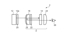
- FIG. 1 is a schematic diagram showing a general configuration of a display system according to one embodiment of the present invention.
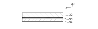
- FIG. 2 is a schematic cross-sectional view showing an example of a laminate used in a reflective section of the display system shown in FIG. 1.
- FIG. FIG. 2 is a schematic perspective view showing an example of a multilayer structure included in a reflective polarizing film.
- Refractive index (nx, ny, nz) "nx" is the refractive index in the direction in which the in-plane refractive index is maximum (i.e., slow axis direction), and "ny” is the direction perpendicular to the slow axis in the plane (i.e., fast axis direction) "nz” is the refractive index in the thickness direction.
- Refractive index (nx, ny, nz) "nx" is the refractive index in the direction in which the in-plane refractive index is maximum (i.e., slow axis direction), and "ny” is the direction perpendicular to the slow axis in the plane (i.e., fast axis direction) "nz” is the refractive index in the thickness direction.
- In-plane phase difference (Re) "Re( ⁇ )” is an in-plane retardation measured with light having a wavelength of ⁇ nm at 23°C.
- Re(550) is an in-plane retardation measured with light having a wavelength of 550 nm at 23°C.
- Phase difference in thickness direction (Rth) is a retardation in the thickness direction measured with light having a wavelength of ⁇ nm at 23°C.
- Rth (550) is the retardation in the thickness direction measured with light having a wavelength of 550 nm at 23°C.
- FIG. 1 is a schematic diagram showing the general configuration of a display system according to one embodiment of the present invention.
- FIG. 1 schematically shows the arrangement, shape, etc. of each component of the display system 2.
- the display system 2 includes a display element 12, a reflection section 14, a first lens section 16, a half mirror 18, a first retardation member 20, a second retardation member 22, and a second lens section 24.
- the reflecting section 14 is arranged at the front of the display element 12 on the display surface 12a side, and can reflect the light emitted from the display element 12.
- the first lens section 16 is arranged on the optical path between the display element 12 and the reflection section 14, and the half mirror 18 is arranged between the display element 12 and the first lens section 16.
- the first retardation member 20 is arranged on the optical path between the display element 12 and the half mirror 18, and the second retardation member 22 is arranged on the optical path between the half mirror 18 and the reflection section 14.
- lens section The components disposed in front of the half mirror (in the illustrated example, the half mirror 18, the first lens section 16, the second retardation member 22, the reflection section 14, and the second lens section 24) are collectively called a lens section (lens section). 4).
- the display element 12 is, for example, a liquid crystal display or an organic EL display, and has a display surface 12a for displaying images.
- the light emitted from the display surface 12a passes through a polarizing member (typically, a polarizing film) that may be included in the display element 12, and is emitted as first linearly polarized light.
- a polarizing member typically, a polarizing film
- the first retardation member 20 is a ⁇ /4 member that can convert the first linearly polarized light incident on the first retardation member 20 into first circularly polarized light (hereinafter, the first retardation member is referred to as the first (sometimes referred to as a ⁇ /4 member). Note that the first retardation member 20 may be provided integrally with the display element 12.
- the half mirror 18 transmits the light emitted from the display element 12 and reflects the light reflected by the reflection section 14 toward the reflection section 14 .
- the half mirror 18 is provided integrally with the first lens section 16.
- the second retardation member 22 is a ⁇ /4 member that can transmit the light reflected by the reflection part 14 and the half mirror 18 through the reflection part 14 including a reflective polarizing member (hereinafter referred to as the second retardation member). (sometimes referred to as the second ⁇ /4 member). Note that the second retardation member 22 may be provided integrally with the first lens portion 16.
- the first circularly polarized light emitted from the first ⁇ /4 member 20 passes through the half mirror 18 and the first lens section 16, and is converted into second linearly polarized light by the second ⁇ /4 member 22. .
- the second linearly polarized light emitted from the second ⁇ /4 member 22 is reflected toward the half mirror 18 without passing through the reflective polarizing member included in the reflecting section 14 .
- the polarization direction of the second linearly polarized light incident on the reflective polarizing member included in the reflecting section 14 is the same direction as the reflection axis of the reflective polarizing member. Therefore, the second linearly polarized light incident on the reflection section is reflected by the reflective polarizing member.
- the second linearly polarized light reflected by the reflection section 14 is converted into second circularly polarized light by the second ⁇ /4 member 22, and the second circularly polarized light emitted from the second ⁇ /4 member 22 is converted into second circularly polarized light by the second ⁇ /4 member 22.
- the light passes through one lens section 16 and is reflected by a half mirror 18.
- the second circularly polarized light reflected by the half mirror 18 passes through the first lens section 16 and is converted into third linearly polarized light by the second ⁇ /4 member 22.
- the third linearly polarized light passes through the reflective polarizing member included in the reflecting section 14.
- the polarization direction of the third linearly polarized light incident on the reflective polarizing member included in the reflecting section 14 is the same direction as the transmission axis of the reflective polarizing member. Therefore, the third linearly polarized light that has entered the reflecting section 14 is transmitted through the reflective polarizing member.
- the light that has passed through the reflection section 14 passes through the second lens section 24 and enters the user's eyes 26.
- the absorption axis of the polarizing member included in the display element 12 and the reflection axis of the reflective polarizing member included in the reflecting section 14 may be arranged substantially parallel to each other, or may be arranged substantially perpendicular to each other.
- the angle between the absorption axis of the polarizing member included in the display element 12 and the slow axis of the first retardation member 20 is, for example, 40° to 50°, may be 42° to 48°, and is about 45°. It may be °.
- the angle between the absorption axis of the polarizing member included in the display element 12 and the slow axis of the second retardation member 22 is, for example, 40° to 50°, may be 42° to 48°, and is about 45°. It may be °.
- the in-plane retardation Re (550) of the first retardation member 20 is, for example, 100 nm to 190 nm, may be 110 nm to 180 nm, may be 130 nm to 160 nm, or may be 135 nm to 155 nm. .
- the first retardation member 20 preferably exhibits inverse dispersion wavelength characteristics in which the retardation value increases depending on the wavelength of the measurement light.
- Re(450)/Re(550) of the first retardation member 20 is, for example, 0.75 or more and less than 1, and may be 0.8 or more and 0.95 or less.
- the in-plane retardation Re (550) of the second retardation member 22 is, for example, 100 nm to 190 nm, may be 110 nm to 180 nm, may be 130 nm to 160 nm, or may be 135 nm to 155 nm. .
- the second retardation member 22 preferably exhibits inverse dispersion wavelength characteristics in which the retardation value increases depending on the wavelength of the measurement light.
- Re(450)/Re(550) of the second retardation member 22 is, for example, 0.75 or more and less than 1, and may be 0.8 or more and 0.95 or less.
- the reflecting section 14 may include an absorbing polarizing member.
- the absorptive polarizing member may be placed in front of the reflective polarizing member.
- the reflection axis of the reflective polarizing member and the absorption axis of the absorptive polarizing member may be arranged substantially parallel to each other, and the transmission axis of the reflective polarizing member and the transmission axis of the absorptive polarizing member may be arranged substantially parallel to each other.
- the reflecting section 14 may include a laminate having a reflective polarizing member and an absorbing polarizing member.
- FIG. 2 is a schematic cross-sectional view showing an example of a laminate used in the reflective section of the display system shown in FIG. 1.
- the laminate 30 includes a reflective polarizing member 32 and an absorbing polarizing member 34, and the reflective polarizing member 32 and the absorbing polarizing member 34 are laminated with an adhesive layer 36 in between.
- the adhesive layer By using the adhesive layer, the reflective polarizing member 32 and the absorbing polarizing member 34 are fixed, and it is possible to prevent misalignment of the axis arrangement between the reflective axis and the absorption axis (the transmission axis and the transmission axis). Further, it is possible to suppress the adverse effects of an air layer that may be formed between the reflective polarizing member 32 and the absorbing polarizing member 34.
- the adhesive layer 36 may be formed of an adhesive or a pressure-sensitive adhesive.
- the thickness of the adhesive layer 36 is, for example, 0.05 ⁇ m to 30 ⁇ m, preferably 3 ⁇ m to 20 ⁇ m, and more preferably 5 ⁇ m to 15 ⁇ m.
- the reflective polarizing member can transmit polarized light parallel to its transmission axis (typically, linearly polarized light) while maintaining its polarized state, and can reflect light in other polarized states.
- the reflective polarizing member is typically composed of a film having a multilayer structure (sometimes referred to as a reflective polarizing film).
- the thickness of the reflective polarizing member is, for example, 10 ⁇ m to 150 ⁇ m, preferably 20 ⁇ m to 100 ⁇ m, and more preferably 30 ⁇ m to 60 ⁇ m.
- FIG. 3 is a schematic perspective view showing an example of a multilayer structure included in a reflective polarizing film.
- the multilayer structure 32a has layers A having birefringence and layers B having substantially no birefringence alternating.
- the total number of layers making up the multilayer structure may be between 50 and 1000.
- the refractive index nx in the x-axis direction of the A layer is larger than the refractive index ny in the y-axis direction, and the refractive index nx in the x-axis direction and the refractive index ny in the y-axis direction of the B layer are substantially the same,
- the refractive index difference between layer A and layer B is large in the x-axis direction and substantially zero in the y-axis direction.
- the x-axis direction can become the reflection axis
- the y-axis direction can become the transmission axis.
- the refractive index difference between layer A and layer B in the x-axis direction is preferably 0.2 to 0.3.
- the above layer A is typically made of a material that exhibits birefringence when stretched.
- materials include, for example, naphthalene dicarboxylic acid polyesters (eg, polyethylene naphthalate), polycarbonates, and acrylic resins (eg, polymethyl methacrylate).
- the B layer is typically made of a material that does not substantially exhibit birefringence even when stretched. Examples of such materials include copolyesters of naphthalene dicarboxylic acid and terephthalic acid.
- the multilayer structure may be formed by a combination of coextrusion and stretching. For example, after extruding the material constituting layer A and the material constituting layer B, they are multilayered (for example, using a multiplier). The obtained multilayer laminate is then stretched.
- the x-axis direction in the illustrated example may correspond to the stretching direction.
- reflective polarizing films include, for example, 3M's product names "DBEF” and “APF” and Nitto Denko's product name "APCF”.
- the cross transmittance (Tc) of the reflective polarizing member (reflective polarizing film) may be, for example, 0.01% to 3%.
- the single transmittance (Ts) of the reflective polarizing member (reflective polarizing film) is, for example, 43% to 49%, preferably 45% to 47%.
- the degree of polarization (P) of the reflective polarizing member (reflective polarizing film) can be, for example, 92% to 99.99%.
- the absorption type polarizing member may typically include a resin film (sometimes referred to as an absorption type polarizing film) containing a dichroic substance.
- the thickness of the absorption type polarizing film is, for example, 1 ⁇ m or more and 20 ⁇ m or less, may be 2 ⁇ m or more and 15 ⁇ m or less, may be 12 ⁇ m or less, may be 10 ⁇ m or less, or may be 8 ⁇ m or less, It may be 5 ⁇ m or less.
- the above-mentioned absorption type polarizing film may be produced from a single layer resin film, or may be produced using a laminate of two or more layers.
- a hydrophilic polymer film such as a polyvinyl alcohol (PVA) film, a partially formalized PVA film, or a partially saponified ethylene/vinyl acetate copolymer film is coated with iodine or dichloromethane.
- An absorption type polarizing film can be obtained by performing a dyeing treatment with a dichroic substance such as a color dye, a stretching treatment, and the like. Among these, an absorption type polarizing film obtained by dyeing a PVA film with iodine and uniaxially stretching it is preferred.
- the above-mentioned staining with iodine is performed, for example, by immersing the PVA-based film in an iodine aqueous solution.
- the stretching ratio of the above-mentioned uniaxial stretching is preferably 3 to 7 times. Stretching may be performed after the dyeing process or may be performed while dyeing. Alternatively, it may be dyed after being stretched. If necessary, the PVA film is subjected to swelling treatment, crosslinking treatment, washing treatment, drying treatment, etc.
- the laminate produced using the above-mentioned laminate of two or more layers is a laminate of a resin base material and a PVA resin layer (PVA resin film) laminated on the resin base material, or a laminate of a resin base material and a PVA resin layer (PVA resin film) laminated on the resin base material, or Examples include a laminate of a material and a PVA-based resin layer formed by coating on the resin base material.
- An absorption type polarizing film obtained by using a laminate of a resin base material and a PVA resin layer coated on the resin base material can be obtained by, for example, applying a PVA resin solution to the resin base material, drying it, and applying the resin.
- a PVA-based resin layer on a base material to obtain a laminate of the resin base material and the PVA-based resin layer; stretching and dyeing the laminate to make the PVA-based resin layer an absorption type polarizing film.
- a polyvinyl alcohol resin layer containing a halide and a polyvinyl alcohol resin is formed on one side of the resin base material.
- Stretching typically includes immersing the laminate in an aqueous boric acid solution and stretching.
- the stretching may further include stretching the laminate in air at a high temperature (for example, 95° C. or higher) before stretching in the boric acid aqueous solution, if necessary.
- the laminate is preferably subjected to a drying shrinkage treatment in which the laminate is heated while being conveyed in the longitudinal direction to shrink by 2% or more in the width direction.
- the manufacturing method of this embodiment includes subjecting the laminate to an in-air auxiliary stretching process, a dyeing process, an underwater stretching process, and a drying shrinkage process in this order.
- the obtained resin base material/absorption type polarizing film laminate may be used as is (that is, the resin base material may be used as a protective layer of the absorption type polarizing film), or the resin base material/absorption type polarizing film laminate may be used as is.
- Any suitable protective layer depending on the purpose may be laminated on the peeled surface from which the resin base material is peeled off, or on the surface opposite to the peeled surface. Details of the method for manufacturing such an absorption type polarizing film are described in, for example, Japanese Patent Application Publication No. 2012-73580 and Japanese Patent No. 6470455. The entire descriptions of these publications are incorporated herein by reference.
- the orthogonal transmittance (Tc) of the absorption type polarizing member (absorption type polarizing film) is preferably 0.5% or less, more preferably 0.1% or less, and still more preferably 0.05% or less. be.
- the single transmittance (Ts) of the absorption type polarizing member (absorption type polarizing film) is, for example, 41.0% to 45.0%, preferably 42.0% or more.
- the degree of polarization (P) of the absorption type polarizing member (absorption type polarizing film) is, for example, 99.0% to 99.997%, preferably 99.9% or more.
- the orthogonal transmittance (Tc) of the reflective part is preferably 0.5% or less, more preferably 0.1% or less, and still more preferably 0.05% or less. By satisfying such orthogonal transmittance, visibility of afterimages (ghosts) by the user can be suppressed, and excellent display characteristics can be achieved.
- the single transmittance (Ts) of the reflective portion is preferably 40.0% to 45.0%, more preferably 41.0% or more.
- the degree of polarization (P) of the reflective portion is preferably 99.0% to 99.997%, more preferably 99.9% or more.
- the transmission axis reflectance of the reflective portion (when polarized light in the transmission axis direction is incident on the reflective portion) is preferably 10% or less, may be 9% or less, and may be 8% or less. In most cases, it may be 7% or less.
- the transmission axis reflectance there are few depolarization components, it is possible to suppress the user's visual recognition of afterimages (ghosts), and it is possible to realize excellent display characteristics.
- the above-mentioned orthogonal transmittance (Tc) can be satisfactorily achieved.
- the optical properties of the reflective section may correspond to the optical properties of a reflective polarizing member, or may correspond to the optical properties of a laminate of a reflective polarizing member and an absorbing polarizing member.
- the optical characteristics of the reflective section described above can be achieved extremely well by combining a reflective polarizing member with an absorbing polarizing member.
- the transmission axis reflectance of the reflective polarizing member (when polarized light in the transmission axis direction is incident on the reflective polarizing member) can be, for example, 7.5% or more. For example, it may be 9% or more. For example, it may be 11% or more.
- the thickness, single transmittance, orthogonal transmittance, and degree of polarization are values measured by the following measuring method.
- ⁇ Thickness> The thickness of 10 ⁇ m or less was measured using a scanning electron microscope (manufactured by JEOL Ltd., product name “JSM-7100F”). Thickness exceeding 10 ⁇ m was measured using a digital micrometer (manufactured by Anritsu Corporation, product name “KC-351C”).
- thermoplastic resin base material a long, amorphous isophthalic copolymerized polyethylene terephthalate film (thickness: 100 ⁇ m) having a water absorption rate of 0.75% and a Tg of about 75° C. was used.
- One side of the resin base material was subjected to corona treatment.
- Iodine was added to 100 parts by weight of a PVA resin prepared by mixing polyvinyl alcohol (degree of polymerization 4200, degree of saponification 99.2 mol%) and acetoacetyl-modified PVA (manufactured by Mitsubishi Chemical Corporation, product name "Gosenex Z410”) in a ratio of 9:1.
- a PVA aqueous solution (coating liquid) was prepared by dissolving 13 parts by weight of potassium chloride in water.
- the PVA aqueous solution was applied to the corona-treated surface of the resin base material and dried at 60° C. to form a PVA-based resin layer with a thickness of 13 ⁇ m, thereby producing a laminate.
- the obtained laminate was uniaxially stretched free end to 2.4 times in the longitudinal direction (longitudinal direction) between rolls having different circumferential speeds in an oven at 130° C. (in-air auxiliary stretching treatment).
- the laminate was immersed for 30 seconds in an insolubilization bath (boric acid aqueous solution obtained by blending 4 parts by weight of boric acid with 100 parts by weight of water) at a liquid temperature of 40° C. (insolubilization treatment).
- the final polarizing film was added to a dyeing bath (an aqueous iodine solution obtained by mixing iodine and potassium iodide in a weight ratio of 1:7 to 100 parts by weight of water) at a liquid temperature of 30°C. It was immersed for 60 seconds while adjusting the concentration so that the single transmittance (Ts) was 42.0% or more (staining treatment).
- the laminate was immersed in a cleaning bath (an aqueous solution obtained by blending 4 parts by weight of potassium iodide with 100 parts by weight of water) at a liquid temperature of 20° C. (cleaning treatment). Thereafter, while drying in an oven maintained at 90°C, it was brought into contact with a SUS heating roll whose surface temperature was maintained at 75°C for about 2 seconds (drying shrinkage treatment). The shrinkage rate of the laminate in the width direction due to the drying shrinkage treatment was 5.2%. In this way, a 5 ⁇ m thick polarizing film 1 (absorption type polarizing film) was formed on the resin base material.
- a cleaning bath an aqueous solution obtained by blending 4 parts by weight of potassium iodide with 100 parts by weight of water
- a cycloolefin resin film having a thickness of 25 ⁇ m was bonded as a protective layer to the surface of the obtained absorption type polarizing film (the surface on the polarizing film 1 side of the laminate) via an ultraviolet curable adhesive.
- the adhesive layer was coated so that the thickness of the cured adhesive layer was approximately 1 ⁇ m, and the adhesive layers were bonded together using a roll machine. Thereafter, UV light was irradiated from the cycloolefin resin film side to cure the adhesive.
- the resin base material was peeled off to obtain an absorption type polarizing film having a structure of cycloolefin resin film/absorption type polarizing film.
- Example 1-2 and Example 1-3 A reflective film was obtained in the same manner as in Example 1-1, except that the dyeing conditions were changed in the production of polarizing film 1.
- Example 1-4 A reflective part was obtained in the same manner as in Example 1-1 except that the following polarizing film 2 was used instead of polarizing film 1.
- polarizing film 2 A long roll of polyvinyl alcohol (PVA) resin film (manufactured by Kuraray, trade name "PE3000”) with a thickness of 30 ⁇ m was simultaneously uniaxially stretched in the longitudinal direction so as to be 5.9 times larger in the longitudinal direction using a roll stretching machine. After performing swelling, dyeing, crosslinking, and washing treatments in this order, a drying treatment was finally performed to produce a polarizing film 2 with a thickness of 12 ⁇ m. In the above swelling treatment, the film was stretched 2.2 times while being treated with pure water at 20°C.
- PVA polyvinyl alcohol
- the dyeing process is carried out in an aqueous solution at 30°C in which the weight ratio of iodine and potassium iodide is 1:7 and the iodine concentration is adjusted so that the single transmittance of the polarizing film obtained is 42.0% or more. While doing so, it was stretched 1.4 times.
- a two-stage crosslinking treatment was adopted for the crosslinking treatment, and the first crosslinking treatment was performed in an aqueous solution containing boric acid and potassium iodide at 40° C. and stretched to 1.2 times.
- the boric acid content of the aqueous solution for the first stage crosslinking treatment was 5.0% by weight, and the potassium iodide content was 3.0% by weight.
- the film was stretched to 1.6 times while being treated in an aqueous solution containing boric acid and potassium iodide at 65°C.
- the boric acid content of the aqueous solution for the second stage crosslinking treatment was 4.3% by weight, and the potassium iodide content was 5.0% by weight.
- washing treatment was performed with a potassium iodide aqueous solution at 20°C.
- the potassium iodide content of the aqueous solution for cleaning treatment was 2.6% by weight.
- a polarizing film 2 was obtained by drying at 70° C. for 5 minutes.
- Example 1-5 A reflective film was obtained in the same manner as in Example 1-4, except that the conditions for the dyeing treatment were changed in the production of polarizing film 2.
- Example 1-1 to Example 1 Example 1-1 to Example 1 except that reflective polarizing film 2 (Ts: 47.0%, Tc: 2.97%, P: 93.1%) was used instead of reflective polarizing film 1.
- a reflective film was obtained in the same manner as in Example 1-5.
- Example 3-1 to Example 3-5 Example 1-1 to Example 1 except that reflective polarizing film 3 (Ts: 45.7%, Tc: 0.011%, P: 99.97%) was used instead of reflective polarizing film 1. A reflective film was obtained in the same manner as in Example 1-5.
- Reflective polarizing film 1 (Ts: 46.8%, Tc: 1.54%, P: 96.4%) was used as the film for the reflective section.
- Reflective polarizing film 2 (Ts: 47.0%, Tc: 2.97%, P: 93.1%) was used as the film for the reflective section.
- Reflective polarizing film 3 (Ts: 45.7%, Tc: 0.011%, P: 99.97%) was used as the film for the reflective section.
- the present invention is not limited to the above embodiments, and various modifications are possible.
- it can be replaced with a configuration that is substantially the same as the configuration shown in the above embodiment, a configuration that has the same effect, or a configuration that can achieve the same objective.
- the lens section according to the embodiment of the present invention can be used, for example, in a display body such as VR goggles.
Landscapes
- Physics & Mathematics (AREA)
- General Physics & Mathematics (AREA)
- Optics & Photonics (AREA)
- Engineering & Computer Science (AREA)
- Multimedia (AREA)
- Signal Processing (AREA)
- Polarising Elements (AREA)
Abstract
Description
2.上記1に記載の表示方法において、上記反射型偏光部材の反射軸と上記吸収型偏光部材の吸収軸とは互いに平行に配置されてもよい。
3.上記1または2に記載の表示方法において、上記第一レンズ部と上記ハーフミラーとは一体に設けられてもよい。
4.上記1から3のいずれかに記載の表示方法は、上記反射型偏光部材を透過した光を、第二レンズ部を透過させるステップを有してもよい。
5.上記1から4のいずれかに記載の表示方法において、上記偏光部材の吸収軸と上記第1のλ/4部材の遅相軸とのなす角度は40°~50°であってもよく、上記偏光部材の吸収軸と上記第2のλ/4部材の遅相軸とのなす角度は40°~50°であってもよい。
6.上記1から5のいずれかに記載の表示方法において、上記反射部は、上記反射型偏光部材と上記吸収型偏光部材との積層体を有してもよい。
7.上記6に記載の表示方法において、上記反射型偏光部材と上記吸収型偏光部材とは接着層を介して積層されてもよい。
本明細書における用語および記号の定義は下記の通りである。
(1)屈折率(nx、ny、nz)
「nx」は面内の屈折率が最大になる方向(すなわち、遅相軸方向)の屈折率であり、「ny」は面内で遅相軸と直交する方向(すなわち、進相軸方向)の屈折率であり、「nz」は厚み方向の屈折率である。
(2)面内位相差(Re)
「Re(λ)」は、23℃における波長λnmの光で測定した面内位相差である。例えば、「Re(550)」は、23℃における波長550nmの光で測定した面内位相差である。Re(λ)は、層(フィルム)の厚みをd(nm)としたとき、式:Re(λ)=(nx-ny)×dによって求められる。
(3)厚み方向の位相差(Rth)
「Rth(λ)」は、23℃における波長λnmの光で測定した厚み方向の位相差である。例えば、「Rth(550)」は、23℃における波長550nmの光で測定した厚み方向の位相差である。Rth(λ)は、層(フィルム)の厚みをd(nm)としたとき、式:Rth(λ)=(nx-nz)×dによって求められる。
(4)Nz係数
Nz係数は、Nz=Rth/Reによって求められる。
(5)角度
本明細書において角度に言及するときは、当該角度は基準方向に対して時計回りおよび反時計回りの両方を包含する。したがって、例えば「45°」は±45°を意味する。
<厚み>
10μm以下の厚みは、走査型電子顕微鏡(日本電子社製、製品名「JSM-7100F」)を用いて測定した。10μmを超える厚みは、デジタルマイクロメーター(アンリツ社製、製品名「KC-351C」)を用いて測定した。
<単体透過率、直交透過率および偏光度>
反射型偏光フィルムおよび吸収型偏光膜(吸収型偏光フィルム)について、紫外可視分光光度計(大塚電子社製、「LPF200」)を用いて、単体透過率Ts、平行透過率Tpおよび直交透過率Tcを測定した。Ts、TpおよびTcは、JIS Z8701の2度視野(C光源)により測定して視感度補正を行なったY値である。
また、得られたTpおよびTcから、下記式により偏光度Pを求めた。
偏光度P(%)={(Tp-Tc)/(Tp+Tc)}1/2×100
(偏光膜1の作製)
熱可塑性樹脂基材として、長尺状で、吸水率0.75%、Tg約75℃である、非晶質のイソフタル共重合ポリエチレンテレフタレートフィルム(厚み:100μm)を用いた。樹脂基材の片面に、コロナ処理を施した。
ポリビニルアルコール(重合度4200、ケン化度99.2モル%)およびアセトアセチル変性PVA(三菱ケミカル社製、商品名「ゴーセネックスZ410」)を9:1で混合したPVA系樹脂100重量部に、ヨウ化カリウム13重量部を添加したものを水に溶かし、PVA水溶液(塗布液)を調製した。
樹脂基材のコロナ処理面に、上記PVA水溶液を塗布して60℃で乾燥することにより、厚み13μmのPVA系樹脂層を形成し、積層体を作製した。
得られた積層体を、130℃のオーブン内で周速の異なるロール間で縦方向(長手方向)に2.4倍に自由端一軸延伸した(空中補助延伸処理)。
次いで、積層体を、液温40℃の不溶化浴(水100重量部に対して、ホウ酸を4重量部配合して得られたホウ酸水溶液)に30秒間浸漬させた(不溶化処理)。
次いで、液温30℃の染色浴(水100重量部に対して、ヨウ素とヨウ化カリウムを1:7の重量比で配合して得られたヨウ素水溶液)に、最終的に得られる偏光膜の単体透過率(Ts)が42.0%以上となるように濃度を調整しながら60秒間浸漬させた(染色処理)。
次いで、液温40℃の架橋浴(水100重量部に対して、ヨウ化カリウムを3重量部配合し、ホウ酸を5重量部配合して得られたホウ酸水溶液)に30秒間浸漬させた(架橋処理)。
その後、積層体を、液温70℃のホウ酸水溶液(ホウ酸濃度4重量%、ヨウ化カリウム濃度5重量%)に浸漬させながら、周速の異なるロール間で縦方向(長手方向)に総延伸倍率が5.5倍となるように一軸延伸を行った(水中延伸処理)。
その後、積層体を液温20℃の洗浄浴(水100重量部に対して、ヨウ化カリウムを4重量部配合して得られた水溶液)に浸漬させた(洗浄処理)。
その後、90℃に保たれたオーブン中で乾燥しながら、表面温度が75℃に保たれたSUS製の加熱ロールに約2秒接触させた(乾燥収縮処理)。乾燥収縮処理による積層体の幅方向の収縮率は5.2%であった。
このようにして、樹脂基材上に厚み5μmの偏光膜1(吸収型偏光膜)を形成した。
得られた吸収型偏光膜の表面(積層体の偏光膜1側の面)に、保護層として厚み25μmのシクロオレフィン系樹脂フィルムを、紫外線硬化型接着剤を介して貼り合わせた。具体的には、硬化後の接着剤層の厚みが約1μmになるように塗工し、ロール機を使用して貼り合わせた。その後、UV光線をシクロオレフィン系樹脂フィルム側から照射して接着剤を硬化させた。次いで、樹脂基材を剥離し、シクロオレフィン系樹脂フィルム/吸収型偏光膜の構成を有する吸収型偏光フィルムを得た。
反射型偏光フィルム1(Ts:46.8%、Tc:1.54%、P:96.4%)に、吸収型偏光フィルムを、反射型偏光フィルム1の反射軸と吸収型偏光膜の吸収軸とが互いに平行に配置されるように、粘着剤を介して貼り合わせ、反射部用フィルム(積層フィルム)を得た。
偏光膜1の作製において、染色処理の条件を変更したこと以外は実施例1-1と同様にして、反射部用フィルムを得た。
偏光膜1のかわりに下記の偏光膜2を用いたこと以外は実施例1-1と同様にして、反射部用を得た。
(偏光膜2の作製)
厚み30μmのポリビニルアルコール(PVA)系樹脂フィルム(クラレ製、商品名「PE3000」)の長尺ロールを、ロール延伸機により長手方向に5.9倍になるように長手方向に一軸延伸しながら同時に膨潤、染色、架橋、洗浄処理をこの順で施した後、最後に乾燥処理を施すことにより、厚み12μmの偏光膜2を作製した。
上記膨潤処理は20℃の純水で処理しながら2.2倍に延伸した。次いで、染色処理は得られる偏光膜の単体透過率が42.0%以上となるようにヨウ素濃度が調整されたヨウ素とヨウ化カリウムの重量比が1:7である30℃の水溶液中において処理しながら1.4倍に延伸した。次いで、架橋処理は、2段階の架橋処理を採用し、1段階目の架橋処理は40℃のホウ酸とヨウ化カリウムを溶解した水溶液において処理しながら1.2倍に延伸した。1段階目の架橋処理の水溶液のホウ酸含有量は5.0重量%で、ヨウ化カリウム含有量は3.0重量%とした。2段階目の架橋処理は65℃のホウ酸とヨウ化カリウムを溶解した水溶液において処理しながら1.6倍に延伸した。2段階目の架橋処理の水溶液のホウ酸含有量は4.3重量%で、ヨウ化カリウム含有量は5.0重量%とした。次いで、洗浄処理は、20℃のヨウ化カリウム水溶液で処理した。洗浄処理の水溶液のヨウ化カリウム含有量は2.6重量%とした。最後に、70℃で5分間乾燥処理して偏光膜2を得た。
偏光膜2の作製において、染色処理の条件を変更したこと以外は実施例1-4と同様にして、反射部用フィルムを得た。
反射型偏光フィルム1のかわりに反射型偏光フィルム2(Ts:47.0%、Tc:2.97%、P:93.1%)を用いたこと以外は実施例1-1から実施例1-5と同様にして、反射部用フィルムを得た。
反射型偏光フィルム1のかわりに反射型偏光フィルム3(Ts:45.7%、Tc:0.011%、P:99.97%)を用いたこと以外は実施例1-1から実施例1-5と同様にして、反射部用フィルムを得た。
反射部用フィルムとして、反射型偏光フィルム1(Ts:46.8%、Tc:1.54%、P:96.4%)を用いた。
反射部用フィルムとして、反射型偏光フィルム2(Ts:47.0%、Tc:2.97%、P:93.1%)を用いた。
反射部用フィルムとして、反射型偏光フィルム3(Ts:45.7%、Tc:0.011%、P:99.97%)を用いた。
<評価>
・透過軸透過率
反射部用フィルムについて、紫外可視近赤外分光光度計(日立ハイテクサイエンス社製、「U-4100」)を用いて、反射部用フィルムに含まれる反射型偏光フィルムの透過軸方向の偏光を、反射型偏光フィルム側から入射させ、透過軸反射率を測定した。

4 レンズ部
12 表示素子
14 反射部
16 第一レンズ部
18 ハーフミラー
20 第一位相差部材
22 第二位相差部材
24 第二レンズ部
30 積層体
32 反射型偏光部材
34 吸収型偏光部材
36 接着層
Claims (7)
- 偏光部材および第1のλ/4部材を介して出射された画像を表す光を、ハーフミラーおよび第一レンズ部を通過させるステップと、
前記ハーフミラーおよび前記第一レンズ部を通過した光を、第2のλ/4部材を通過させるステップと、
前記第2のλ/4部材を通過した光を、反射型偏光部材を含む反射部で前記ハーフミラーに向けて反射させるステップと、
前記反射部および前記ハーフミラーで反射させた光を、前記第2のλ/4部材により前記反射部の前記反射型偏光部材を透過可能にするステップと、
前記反射型偏光部材を透過した光を、吸収型偏光部材を透過させるステップと、を有し、
前記吸収型偏光部材により、前記反射型偏光部材側から、前記反射型偏光部材の透過軸方向の偏光を入射させたときの透過軸反射率を0.5%以上低減させる、
表示方法。 - 前記反射型偏光部材の反射軸と前記吸収型偏光部材の吸収軸とは互いに平行に配置される、請求項1に記載の表示方法。
- 前記第一レンズ部と前記ハーフミラーとは一体に設けられる、請求項1に記載の表示方法。
- 前記反射型偏光部材を透過した光を、第二レンズ部を透過させるステップを有する、請求項1に記載の表示方法。
- 前記偏光部材の吸収軸と前記第1のλ/4部材の遅相軸とのなす角度は40°~50°であり、
前記偏光部材の吸収軸と前記第2のλ/4部材の遅相軸とのなす角度は40°~50°である、請求項1に記載の表示方法。 - 前記反射部は、前記反射型偏光部材と前記吸収型偏光部材との積層体を有する、請求項1に記載の表示方法。
- 前記反射型偏光部材と前記吸収型偏光部材とは接着層を介して積層される、請求項6に記載の表示方法。
Priority Applications (4)
| Application Number | Priority Date | Filing Date | Title |
|---|---|---|---|
| EP23770318.6A EP4495664A4 (en) | 2022-03-14 | 2023-02-24 | DISPLAY METHOD |
| KR1020247027858A KR20240155215A (ko) | 2022-03-14 | 2023-02-24 | 표시 방법 |
| US18/845,581 US20250208421A1 (en) | 2022-03-14 | 2023-02-24 | Display method |
| CN202380024835.8A CN118805119A (zh) | 2022-03-14 | 2023-02-24 | 显示方法 |
Applications Claiming Priority (6)
| Application Number | Priority Date | Filing Date | Title |
|---|---|---|---|
| JP2022039285 | 2022-03-14 | ||
| JP2022039286 | 2022-03-14 | ||
| JP2022-039286 | 2022-03-14 | ||
| JP2022-039285 | 2022-03-14 | ||
| JP2022-077633 | 2022-05-10 | ||
| JP2022077633A JP7516456B2 (ja) | 2022-05-10 | 2022-05-10 | 表示方法 |
Publications (1)
| Publication Number | Publication Date |
|---|---|
| WO2023176359A1 true WO2023176359A1 (ja) | 2023-09-21 |
Family
ID=88023380
Family Applications (1)
| Application Number | Title | Priority Date | Filing Date |
|---|---|---|---|
| PCT/JP2023/006726 Ceased WO2023176359A1 (ja) | 2022-03-14 | 2023-02-24 | 表示方法 |
Country Status (5)
| Country | Link |
|---|---|
| US (1) | US20250208421A1 (ja) |
| EP (1) | EP4495664A4 (ja) |
| KR (1) | KR20240155215A (ja) |
| TW (1) | TWI904412B (ja) |
| WO (1) | WO2023176359A1 (ja) |
Citations (6)
| Publication number | Priority date | Publication date | Assignee | Title |
|---|---|---|---|---|
| JP2002107655A (ja) * | 2000-09-27 | 2002-04-10 | Minolta Co Ltd | 映像表示装置 |
| JP2012073580A (ja) | 2010-09-03 | 2012-04-12 | Nitto Denko Corp | 薄型偏光膜の製造方法 |
| JP6470455B1 (ja) | 2017-09-13 | 2019-02-13 | 日東電工株式会社 | 偏光膜、偏光板、および偏光膜の製造方法 |
| JP2019505854A (ja) * | 2016-01-28 | 2019-02-28 | 深▲セン▼多▲ドゥオ▼新技術有限責任公司Shenzhen Dlodlo New Technology Co., Ltd. | 短距離光拡大モジュール、短距離光拡大方法及び短距離光拡大システム |
| US20200132994A1 (en) * | 2018-07-16 | 2020-04-30 | Shanghai Seeo Optronics Technology Co., Ltd. | Virtual reality display device |
| CN113448101A (zh) * | 2021-06-28 | 2021-09-28 | 歌尔股份有限公司 | 光学模组和头戴显示设备 |
Family Cites Families (7)
| Publication number | Priority date | Publication date | Assignee | Title |
|---|---|---|---|---|
| EP2472301A3 (en) * | 2009-01-29 | 2015-09-02 | Nikon Corporation | Imaging Optical System, Microscope Apparatus Including The Imaging Optical System, and Stereoscopic Microscope Apparatus |
| CN107003555B (zh) * | 2014-12-03 | 2021-01-15 | 夏普株式会社 | 液晶显示装置 |
| CN111344613B (zh) * | 2017-10-09 | 2022-09-27 | 3M创新有限公司 | 光学部件和光学系统 |
| CN108303796B (zh) * | 2018-04-09 | 2020-07-28 | 浙江舜宇光学有限公司 | 目镜 |
| CN112400125B (zh) * | 2018-07-13 | 2024-03-12 | 3M创新有限公司 | 光学系统和光学膜 |
| JP7397683B2 (ja) | 2019-01-25 | 2023-12-13 | 住友化学株式会社 | 有機elディスプレイ用積層体およびそれに用いる円偏光板 |
| CN114945856B (zh) * | 2020-01-15 | 2024-04-09 | 富士胶片株式会社 | 光学系统 |
-
2023
- 2023-02-24 KR KR1020247027858A patent/KR20240155215A/ko not_active Ceased
- 2023-02-24 EP EP23770318.6A patent/EP4495664A4/en active Pending
- 2023-02-24 WO PCT/JP2023/006726 patent/WO2023176359A1/ja not_active Ceased
- 2023-02-24 US US18/845,581 patent/US20250208421A1/en active Pending
- 2023-03-03 TW TW112107896A patent/TWI904412B/zh active
Patent Citations (6)
| Publication number | Priority date | Publication date | Assignee | Title |
|---|---|---|---|---|
| JP2002107655A (ja) * | 2000-09-27 | 2002-04-10 | Minolta Co Ltd | 映像表示装置 |
| JP2012073580A (ja) | 2010-09-03 | 2012-04-12 | Nitto Denko Corp | 薄型偏光膜の製造方法 |
| JP2019505854A (ja) * | 2016-01-28 | 2019-02-28 | 深▲セン▼多▲ドゥオ▼新技術有限責任公司Shenzhen Dlodlo New Technology Co., Ltd. | 短距離光拡大モジュール、短距離光拡大方法及び短距離光拡大システム |
| JP6470455B1 (ja) | 2017-09-13 | 2019-02-13 | 日東電工株式会社 | 偏光膜、偏光板、および偏光膜の製造方法 |
| US20200132994A1 (en) * | 2018-07-16 | 2020-04-30 | Shanghai Seeo Optronics Technology Co., Ltd. | Virtual reality display device |
| CN113448101A (zh) * | 2021-06-28 | 2021-09-28 | 歌尔股份有限公司 | 光学模组和头戴显示设备 |
Non-Patent Citations (1)
| Title |
|---|
| See also references of EP4495664A4 |
Also Published As
| Publication number | Publication date |
|---|---|
| TW202343042A (zh) | 2023-11-01 |
| EP4495664A4 (en) | 2026-03-25 |
| KR20240155215A (ko) | 2024-10-28 |
| US20250208421A1 (en) | 2025-06-26 |
| TWI904412B (zh) | 2025-11-11 |
| EP4495664A1 (en) | 2025-01-22 |
Similar Documents
| Publication | Publication Date | Title |
|---|---|---|
| JP7516458B2 (ja) | レンズ部、積層体、表示体、表示体の製造方法および表示方法 | |
| JP7516456B2 (ja) | 表示方法 | |
| JP7516455B2 (ja) | レンズ部、積層体、表示体、表示体の製造方法および表示方法 | |
| WO2023176359A1 (ja) | 表示方法 | |
| WO2023176357A1 (ja) | レンズ部、積層体、表示体、表示体の製造方法および表示方法 | |
| WO2023176358A1 (ja) | レンズ部、積層体、表示体、表示体の製造方法および表示方法 | |
| JP2023134316A (ja) | レンズ部、積層体、表示体、表示体の製造方法および表示方法 | |
| TWI922419B (zh) | 光學構件組及光學構件組用積層體 | |
| JP7516457B2 (ja) | レンズ部、積層体、表示体、表示体の製造方法および表示方法 | |
| TW202609362A (zh) | 光學構件組及光學構件組用積層體 | |
| TW202607398A (zh) | 光學構件組及光學構件組用積層體 | |
| JP7547456B2 (ja) | レンズ部、表示体および表示方法 | |
| CN118871842A (zh) | 透镜部、层叠体、显示体、显示体的制造方法及显示方法 | |
| US20250208419A1 (en) | Lens part, laminate, display body, and manufacturing method and display method for display body | |
| WO2023176365A1 (ja) | レンズ部、積層体、表示体、表示体の製造方法および表示方法 | |
| WO2023176367A1 (ja) | レンズ部、積層体、表示体、表示体の製造方法および表示方法 | |
| WO2025126954A1 (ja) | 光学積層体、レンズ部および表示方法 | |
| JP2024122667A (ja) | 表示システム、表示方法、表示体および表示体の製造方法 | |
| WO2023176366A1 (ja) | レンズ部、積層体、表示体、表示体の製造方法および表示方法 | |
| JP2024122668A (ja) | 表示システム、表示方法、表示体および表示体の製造方法 | |
| JP2024095147A (ja) | 表示システム、表示方法、表示体および表示体の製造方法 | |
| JP2024122666A (ja) | 表示システム、表示方法、表示体および表示体の製造方法 | |
| JP2023166851A (ja) | レンズ部、積層体、表示体、表示体の製造方法および表示方法 | |
| JP2024095148A (ja) | 表示システム、表示方法、表示体および表示体の製造方法 | |
| JP2026014701A (ja) | 光学部材の処理方法および光学部材セットの製造方法 |
Legal Events
| Date | Code | Title | Description |
|---|---|---|---|
| 121 | Ep: the epo has been informed by wipo that ep was designated in this application |
Ref document number: 23770318 Country of ref document: EP Kind code of ref document: A1 |
|
| WWE | Wipo information: entry into national phase |
Ref document number: 202380024835.8 Country of ref document: CN |
|
| WWE | Wipo information: entry into national phase |
Ref document number: 18845581 Country of ref document: US |
|
| WWE | Wipo information: entry into national phase |
Ref document number: 2023770318 Country of ref document: EP |
|
| NENP | Non-entry into the national phase |
Ref country code: DE |
|
| ENP | Entry into the national phase |
Ref document number: 2023770318 Country of ref document: EP Effective date: 20241014 |
|
| WWP | Wipo information: published in national office |
Ref document number: 18845581 Country of ref document: US |