WO2023176548A1 - 非水電解質二次電池 - Google Patents
非水電解質二次電池 Download PDFInfo
- Publication number
- WO2023176548A1 WO2023176548A1 PCT/JP2023/008318 JP2023008318W WO2023176548A1 WO 2023176548 A1 WO2023176548 A1 WO 2023176548A1 JP 2023008318 W JP2023008318 W JP 2023008318W WO 2023176548 A1 WO2023176548 A1 WO 2023176548A1
- Authority
- WO
- WIPO (PCT)
- Prior art keywords
- positive electrode
- end region
- width
- stiffness
- secondary battery
- Prior art date
- Legal status (The legal status is an assumption and is not a legal conclusion. Google has not performed a legal analysis and makes no representation as to the accuracy of the status listed.)
- Ceased
Links
Images
Classifications
-
- H—ELECTRICITY
- H01—ELECTRIC ELEMENTS
- H01M—PROCESSES OR MEANS, e.g. BATTERIES, FOR THE DIRECT CONVERSION OF CHEMICAL ENERGY INTO ELECTRICAL ENERGY
- H01M10/00—Secondary cells; Manufacture thereof
- H01M10/05—Accumulators with non-aqueous electrolyte
- H01M10/058—Construction or manufacture
- H01M10/0587—Construction or manufacture of accumulators having only wound construction elements, i.e. wound positive electrodes, wound negative electrodes and wound separators
-
- H—ELECTRICITY
- H01—ELECTRIC ELEMENTS
- H01M—PROCESSES OR MEANS, e.g. BATTERIES, FOR THE DIRECT CONVERSION OF CHEMICAL ENERGY INTO ELECTRICAL ENERGY
- H01M10/00—Secondary cells; Manufacture thereof
- H01M10/04—Construction or manufacture in general
- H01M10/0431—Cells with wound or folded electrodes
-
- H—ELECTRICITY
- H01—ELECTRIC ELEMENTS
- H01M—PROCESSES OR MEANS, e.g. BATTERIES, FOR THE DIRECT CONVERSION OF CHEMICAL ENERGY INTO ELECTRICAL ENERGY
- H01M10/00—Secondary cells; Manufacture thereof
- H01M10/05—Accumulators with non-aqueous electrolyte
- H01M10/052—Li-accumulators
- H01M10/0525—Rocking-chair batteries, i.e. batteries with lithium insertion or intercalation in both electrodes; Lithium-ion batteries
-
- H—ELECTRICITY
- H01—ELECTRIC ELEMENTS
- H01M—PROCESSES OR MEANS, e.g. BATTERIES, FOR THE DIRECT CONVERSION OF CHEMICAL ENERGY INTO ELECTRICAL ENERGY
- H01M4/00—Electrodes
- H01M4/02—Electrodes composed of, or comprising, active material
- H01M4/13—Electrodes for accumulators with non-aqueous electrolyte, e.g. for lithium-accumulators; Processes of manufacture thereof
-
- H—ELECTRICITY
- H01—ELECTRIC ELEMENTS
- H01M—PROCESSES OR MEANS, e.g. BATTERIES, FOR THE DIRECT CONVERSION OF CHEMICAL ENERGY INTO ELECTRICAL ENERGY
- H01M4/00—Electrodes
- H01M4/02—Electrodes composed of, or comprising, active material
- H01M2004/021—Physical characteristics, e.g. porosity, surface area
-
- H—ELECTRICITY
- H01—ELECTRIC ELEMENTS
- H01M—PROCESSES OR MEANS, e.g. BATTERIES, FOR THE DIRECT CONVERSION OF CHEMICAL ENERGY INTO ELECTRICAL ENERGY
- H01M4/00—Electrodes
- H01M4/02—Electrodes composed of, or comprising, active material
- H01M2004/026—Electrodes composed of, or comprising, active material characterised by the polarity
- H01M2004/028—Positive electrodes
-
- Y—GENERAL TAGGING OF NEW TECHNOLOGICAL DEVELOPMENTS; GENERAL TAGGING OF CROSS-SECTIONAL TECHNOLOGIES SPANNING OVER SEVERAL SECTIONS OF THE IPC; TECHNICAL SUBJECTS COVERED BY FORMER USPC CROSS-REFERENCE ART COLLECTIONS [XRACs] AND DIGESTS
- Y02—TECHNOLOGIES OR APPLICATIONS FOR MITIGATION OR ADAPTATION AGAINST CLIMATE CHANGE
- Y02E—REDUCTION OF GREENHOUSE GAS [GHG] EMISSIONS, RELATED TO ENERGY GENERATION, TRANSMISSION OR DISTRIBUTION
- Y02E60/00—Enabling technologies; Technologies with a potential or indirect contribution to GHG emissions mitigation
- Y02E60/10—Energy storage using batteries
-
- Y—GENERAL TAGGING OF NEW TECHNOLOGICAL DEVELOPMENTS; GENERAL TAGGING OF CROSS-SECTIONAL TECHNOLOGIES SPANNING OVER SEVERAL SECTIONS OF THE IPC; TECHNICAL SUBJECTS COVERED BY FORMER USPC CROSS-REFERENCE ART COLLECTIONS [XRACs] AND DIGESTS
- Y02—TECHNOLOGIES OR APPLICATIONS FOR MITIGATION OR ADAPTATION AGAINST CLIMATE CHANGE
- Y02P—CLIMATE CHANGE MITIGATION TECHNOLOGIES IN THE PRODUCTION OR PROCESSING OF GOODS
- Y02P70/00—Climate change mitigation technologies in the production process for final industrial or consumer products
- Y02P70/50—Manufacturing or production processes characterised by the final manufactured product
Definitions
- the present disclosure relates to a non-aqueous electrolyte secondary battery.
- non-aqueous electrolyte secondary batteries such as lithium ion secondary batteries have been used in a wide range of applications such as notebook PCs, power tools, electrically assisted bicycles, and electric vehicles due to their high energy density. Under these circumstances, it is desired to develop a non-aqueous electrolyte secondary battery with higher capacity and excellent life performance.
- Patent Documents 1 and 2 propose heat treating the positive electrode.
- an object of the present disclosure is to provide a nonaqueous electrolyte secondary battery that can suppress foil breakage and deterioration of charge/discharge cycle characteristics when a positive electrode is wound.
- Non-aqueous electrolyte secondary battery including a wound-type electrode body in which a positive electrode and a negative electrode are wound with a separator in between, and a non-aqueous electrolyte, the positive electrode being a positive electrode current collector. and a positive electrode composite layer formed on the positive electrode current collector and containing a positive electrode active material and a binder, the positive electrode is moved from one end in the width direction of the positive electrode to the center side over the entire width of the positive electrode.
- first end region having a width of 1 ⁇ 3 of the width of the positive electrode; a second end region having a width of 1 ⁇ 3 of the total width of the positive electrode from the other end in the width direction of the positive electrode toward the center;
- stiffness values of the first end region and the second end region are the same as those of the central region.
- the stiffness value of the entire positive electrode is lower than the stiffness value, and is characterized in that the stiffness value of the entire positive electrode is in the range of 0.018 N/mm to 0.040 N/mm.
- nonaqueous electrolyte secondary battery that can suppress foil breakage and deterioration of charge/discharge cycle characteristics when a positive electrode is wound.
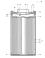
- FIG. 1 is a cross-sectional view of a non-aqueous electrolyte secondary battery that is an example of an embodiment.
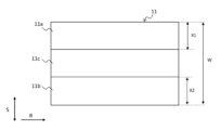
- FIG. 3 is a schematic plan view of the positive electrode in a state before being wound.
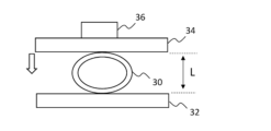
- FIG. 3 is a diagram for explaining a method of measuring stiffness values using a loop stiffness method.
- FIG. 1 is a cross-sectional view of a nonaqueous electrolyte secondary battery that is an example of an embodiment.
- the non-aqueous electrolyte secondary battery 10 shown in FIG. It includes arranged insulating plates 18 and 19 and a battery case 15 that accommodates the above-mentioned members.
- the battery case 15 includes an outer can 16 and a sealing body 17 that closes the opening of the outer can 16.
- the outer can 16 is, for example, a cylindrical metal case with a bottom.
- a gasket 28 is provided between the outer can 16 and the sealing body 17 to ensure airtightness inside the battery.
- the outer can 16 has an overhanging portion 22 that supports the sealing body 17 and has, for example, a part of the side surface overhanging inward.
- the projecting portion 22 is preferably formed in an annular shape along the circumferential direction of the outer can 16, and supports the sealing body 17 on its upper surface.
- the sealing body 17 has a structure in which a filter 23, a lower valve body 24, an insulating member 25, an upper valve body 26, and a cap 27 are stacked in order from the electrode body 14 side.
- Each member constituting the sealing body 17 has, for example, a disk shape or a ring shape, and each member except the insulating member 25 is electrically connected to each other.
- the lower valve body 24 and the upper valve body 26 are connected to each other at their central portions, and an insulating member 25 is interposed between their respective peripheral portions.
- the lower valve body 24 deforms and ruptures so as to push the upper valve body 26 toward the cap 27, and the lower valve body 24 and the upper valve body The current path between bodies 26 is interrupted.
- the upper valve body 26 breaks and gas is discharged from the opening of the cap 27.
- the positive electrode lead 20 attached to the positive electrode 11 extends toward the sealing body 17 side through the through hole of the insulating plate 18, and the negative electrode lead 21 attached to the negative electrode 12 is insulated. It passes through the outside of the plate 19 and extends to the bottom side of the outer can 16.
- the positive electrode lead 20 is connected by welding or the like to the lower surface of the filter 23, which is the bottom plate of the sealing body 17, and the cap 27, which is the top plate of the sealing body 17 and electrically connected to the filter 23, serves as a positive terminal.
- the negative electrode lead 21 is connected to the bottom inner surface of the outer can 16 by welding or the like, and the outer can 16 serves as a negative electrode terminal.
- the positive electrode 11 includes a positive electrode current collector and a positive electrode composite material layer provided on the positive electrode current collector.
- a positive electrode current collector a metal foil such as aluminum that is stable in the potential range of the positive electrode 11, a film having the metal disposed on the surface layer, or the like can be used.
- the positive electrode composite material layer contains a positive electrode active material, a binder, and optionally contains additives such as a conductive material.
- the positive electrode 11 of this embodiment is manufactured, for example, as follows. First, a positive electrode composite slurry containing a positive electrode active material, a conductive material, a binder, etc. is applied onto a positive electrode current collector, and after drying the coating film, the positive electrode composite layer is compressed to form a positive electrode current collector. Obtain the positive electrode formed above. Then, the positive electrode 11 of this embodiment can be manufactured by subjecting the positive electrode to heat treatment, such as by bringing the end region of the positive electrode into contact with a heated roller as described below.
- the thickness of the positive electrode current collector is, for example, 10 ⁇ m or more. Further, the thickness of the positive electrode composite material layer is, for example, 20 ⁇ m or more.
- the density of the positive electrode composite material layer is, for example, 1.60 g/cm 3 or more.
- Examples of the positive electrode active material include lithium metal composite oxides containing transition metal elements such as Co, Mn, and Ni.
- lithium metal composite oxides include Li x CoO 2 , Li x NiO 2 , Li x MnO 2 , Li x Co y Ni 1-y O 2 , Li x Co y M 1-y O z , Li x Ni 1- y M y O z , Li x Mn 2 O 4 , Li x Mn 2-y M y O 4 , LiMPO 4 , Li 2 MPO 4 F (M; Na, Mg, Sc, Y, Mn, Fe, Co, Ni , Cu, Zn, Al, Cr, Pb, Sb, and B, and 0 ⁇ x ⁇ 1.2, 0 ⁇ y ⁇ 0.9, 2.0 ⁇ z ⁇ 2.3).
- the positive electrode active materials are Li x NiO 2 , Li x Co y Ni 1-y O 2 , Li x Ni 1-y M y O z ( M; at least one of Na, Mg, Sc, Y, Mn, Fe, Co, Ni, Cu, Zn, Al, Cr, Pb, Sb, B, 0 ⁇ x ⁇ 1.2, 0 ⁇ y ⁇ 0 .9, 2.0 ⁇ z ⁇ 2.3) and the like.
- binder examples include fluororesins such as polytetrafluoroethylene (PTFE) and polyvinylidene fluoride (PVDF), polyacrylonitrile (PAN), polyimide (PI), acrylic resins, polyolefin resins, and styrene-butadiene rubber ( SBR), nitrile rubber (NBR), carboxymethylcellulose (CMC) or a salt thereof, polyacrylic acid (PAA) or a salt thereof, polyvinyl alcohol (PVA), etc. can be used. These may be used alone or in combination of two or more.
- the content of the binder in the positive electrode composite layer is, for example, preferably 0.5% by mass to 10% by mass, more preferably 1% by mass to 5% by mass.
- Examples of the conductive material include carbon-based particles such as carbon black (CB), acetylene black (AB), Ketjen black, carbon nanotubes (CNT), and graphite. These may be used alone or in combination of two or more.
- FIG. 2 is a schematic plan view of the positive electrode before being wound.
- An arrow S shown in the figure indicates the winding axis direction of the electrode body 14, and an arrow R perpendicular to the arrow S indicates the winding direction of the positive electrode 11 when producing the electrode body 14.
- the positive electrode 11 is moved from one end in the width direction of the positive electrode 11 along the winding axis direction of the electrode body 14 to the center side by a width (X1 ), and from the other end in the width direction of the positive electrode 11 along the winding axis direction of the electrode body 14 to the center side, there is a width ( X2), and a central region 11c sandwiched between the first end region 11a and the second end region 11b.
- the stiffness value of each of the first end region 11a and the second end region 11b is lower than the stiffness value of the central region 11c
- the stiffness value of the entire positive electrode 11 is lower than the stiffness value of the central region 11c.
- the stiffness value is an index of flexibility, and the lower the stiffness value, the more flexible it is.
- the stiffness value is measured by the loop stiffness method described below.
- the stiffness value of the first end region 11a and the second end region 11b is made lower than the stiffness value of the central region 11c to increase the flexibility of the end region. Even when the electrode body 14 is produced by winding, foil breakage of the positive electrode 11 is suppressed.
- the stiffness value can be controlled by heat-treating the positive electrode 11. Specifically, by heat-treating part or all of the first end region 11a and the second end region 11b, the positive electrode current collector etc. in the end region can be softened and the stiffness value can be lowered. .
- the heat treatment is performed, for example, by bringing part or all of the first end region 11a and second end region 11b of the positive electrode 11 into contact with a heated roller.
- first end region 11a and the second end region 11b are heat-treated so that the stiffness value of the entire positive electrode 11 is in the range of 0.018 N/mm to 0.040 N/mm.
- the stiffness value of the entire positive electrode 11 may exceed 0.040 N/mm, but in that case, the first end region 11a and the second end region 11b Even if the stiffness value of the positive electrode 11 is lower than the stiffness value of the central region 11c, foil breakage of the positive electrode 11 may occur.
- the heat treatment temperature of the end region depends on the thickness of the positive electrode 11, etc., but is preferably in the range of 180° C. to 200° C., for example.
- the heat treatment to the central region 11c is not limited, it is easy to control the stiffness value of the entire positive electrode 11 within the range of 0.018 N/mm to 0.040 N/mm. For this reason, it is preferable not to perform heat treatment on the central region 11c.
- the heating temperature of the roller is set at the first end region 11a or the second end region 11b. It is desirable that the temperature be lower than the heat treatment temperature. Note that if part or all of the central region 11c is heat-treated under the same conditions as the end regions, the stiffness value of the entire positive electrode 11 may become lower than 0.018 N/mm. In such a case, it is assumed that the binder formed into a film by the heat treatment is present throughout the positive electrode 11, and the charge/discharge cycle characteristics of the battery are significantly reduced.
- the stiffness values of each of the first end region 11a and the second end region 11b of the positive electrode 11 are lower than the stiffness value of the central region 11c of the positive electrode 11, and the stiffness value of the entire positive electrode 11 is By being in the range of 0.018 N/mm to 0.040 N/mm (preferably in the range of 0.020 N/mm to 0.030 N/mm), foil breakage and charge/discharge cycle characteristics when the positive electrode 11 is wound are improved. It is possible to suppress the decrease in
- the stiffness values of the first end region 11a and the second end region 11b of the positive electrode 11 are, for example, in the range of 0.025 N/mm or less in order to suppress foil breakage when the positive electrode 11 is wound. It is preferable that Further, the stiffness value of the central region 11c of the positive electrode 11 is preferably in a range of 0.020 N/mm or more, for example, in order to suppress deterioration of the charge/discharge cycle characteristics of the battery.
- FIG. 3 is a diagram for explaining a method for measuring stiffness values using the loop stiffness method.
- the loop stiffness method is a method for evaluating the flexibility of a test piece by measuring the stress when pressing a test piece rolled into an annular shape at a predetermined speed. Specifically, first, each region of the positive electrode 11 (first end region 11a, second end region 11b, central region 11c) is cut into a width of each region x length of 80 mm, and both ends are brought together to form a ring. A test piece 30 having an outer circumference of 80 mm is prepared by rolling it into a ball.
- the abutting portion of the test piece 30 is fixed on the lower flat plate 32 and sandwiched between the upper flat plate 34 and the lower flat plate 32.
- the upper flat plate 34 is moved downward at a speed of 1.6 mm/sec to press the outer periphery of the test piece 30, and when the gap L of the test piece 30 becomes 11 mm, the repulsive force of the test piece 30 is measured by the load cell 36. Measure with. In this way, the repulsive forces of at least three test pieces 30 are measured, each of the obtained repulsive forces is converted per width of the test piece, and their average value is taken as the stiffness value of each region.
- the negative electrode 12 includes a negative electrode current collector and a negative electrode composite material layer provided on the negative electrode current collector.
- the negative electrode current collector for example, a foil made of a metal such as copper that is stable in the potential range of the negative electrode, a film having the metal disposed on the surface layer, or the like is used.
- the negative electrode composite material layer includes, for example, a negative electrode active material and a binder.
- the negative electrode 12 is made by applying a negative electrode composite slurry containing a negative electrode active material, a binder, etc. onto a negative electrode current collector, drying the coating film, and then compressing the negative electrode composite material layer to form a negative electrode current collector. It can be manufactured by forming on top.
- the negative electrode active material is, for example, one that can reversibly absorb and release lithium ions, and includes carbon materials such as natural graphite and artificial graphite, metals that alloy with lithium such as silicon (Si) and tin (Sn), and the like. Examples include alloys and composite oxides containing metal elements.
- binder examples include those similar to those for the positive electrode 11.
- the content of the binder in the negative electrode composite layer is, for example, preferably 0.5% by mass to 10% by mass, more preferably 1% by mass to 5% by mass.
- separator 13 for example, a porous sheet having ion permeability and insulation properties is used. Specific examples of porous sheets include microporous thin films, woven fabrics, and nonwoven fabrics. Suitable materials for the separator include olefin resins such as polyethylene and polypropylene, cellulose, and the like.
- the separator 13 may be a laminate having a cellulose fiber layer and a thermoplastic resin fiber layer such as an olefin resin.
- a multilayer separator including a polyethylene layer and a polypropylene layer may be used, or a separator whose surface is coated with a material such as aramid resin or ceramic may be used.
- the non-aqueous electrolyte includes a non-aqueous solvent and an electrolyte salt dissolved in the non-aqueous solvent.
- the non-aqueous solvent for example, esters, ethers, nitriles, amides, and mixed solvents of two or more of these may be used.
- the non-aqueous solvent may contain a halogen-substituted product in which at least a portion of the hydrogen atoms of these solvents are replaced with halogen atoms such as fluorine.
- the non-aqueous electrolyte is not limited to a liquid electrolyte, and may be a solid electrolyte using a gel-like polymer or the like.
- a lithium salt such as LiPF 6 is used as the electrolyte salt.
- Example 1 [Preparation of positive electrode] 95 parts by mass of LiNi 0.7 Co 0.25 Al 0.05 O 2 as a positive electrode active material and 5 parts by mass of graphite as a conductive material were mixed. A positive electrode composite slurry was prepared by dispersing 95 parts by mass of this mixture and 5 parts by mass of polyvinylidene fluoride (PVDF) as a binder in N-methyl-2-pyrrolidone (NMP). The positive electrode composite slurry was applied to both sides of a strip-shaped positive electrode current collector made of aluminum foil with a thickness of 16 ⁇ m, and the coating film was dried by heating.
- PVDF polyvinylidene fluoride
- NMP N-methyl-2-pyrrolidone
- the dried coating film was rolled using a roll press machine to a density of 3.6 g/cc to produce a positive electrode in which positive electrode mixture layers were formed on both sides of the positive electrode current collector. Both ends of this positive electrode in the width direction were passed through a roller heated to 180° C. to perform heat treatment. The width of both ends of the positive electrode that was brought into contact with the heated roller was set to 3% of the total width of the positive electrode.
- the stiffness values of the first end region, second end region, and central region of the positive electrode are greater than the stiffness values of the central region.
- the value was low.
- the stiffness value of the entire positive electrode was 0.040 N/mm. The stiffness value was measured as described above.
- a negative electrode composite slurry was prepared by dispersing 96 parts by mass of artificial graphite as a negative electrode active material, 2 parts by mass of carboxymethyl cellulose (CMC), and 2 parts by mass of styrene-butadiene rubber in water.
- the negative electrode composite slurry was applied to both sides of a band-shaped negative electrode current collector made of copper foil with a thickness of 12 ⁇ m, the coating film was dried by heating, and the coating film dried using a roll press machine had a density of 1.55 g/cc. This was rolled to produce a negative electrode in which negative electrode composite layers were formed on both sides of the negative electrode current collector.
- Non-aqueous electrolyte One portion of LiPF 6 was added to a nonaqueous solvent consisting of a mixture of ethylene carbonate (EC), ethyl methyl carbonate (EMC), and dimethyl carbonate (DMC) at a volume ratio of 20:20:60 (1 atm, 25°C).
- EC ethylene carbonate
- EMC ethyl methyl carbonate
- DMC dimethyl carbonate
- a non-aqueous electrolyte was prepared by dissolving it at a rate of .2 mol/liter.
- a wound type electrode body was produced by winding a positive electrode and a negative electrode with a separator made of olefin resin interposed therebetween.
- Insulating plates were placed above and below the electrode body, and they were inserted into the outer can.
- the negative electrode lead attached to the negative electrode was welded to the bottom of the outer can, and the positive electrode lead attached to the positive electrode was welded to the sealing body.
- Example 2 A positive electrode was produced in the same manner as in Example 1, except that the width of both ends of the positive electrode brought into contact with the heated roller was set to 5% of the total width of the positive electrode. As a result of measuring the stiffness values of the first end region, second end region, and central region of this positive electrode, the stiffness values of the first end region and the second end region are equal to the stiffness values of the central region. The value was lower. Further, the stiffness value of the entire positive electrode was 0.030 N/mm.
- a non-aqueous electrolyte secondary battery was produced in the same manner as in Example 1, except that the above positive electrode was used.
- Example 3 A positive electrode was produced in the same manner as in Example 1, except that the width of both ends of the positive electrode brought into contact with the heated roller was set to 25% of the total width of the positive electrode. As a result of measuring the stiffness values of the first end region, second end region, and central region of this positive electrode, the stiffness values of the first end region and the second end region are equal to the stiffness values of the central region. The value was lower. Further, the stiffness value of the entire positive electrode was 0.025 N/mm.
- a non-aqueous electrolyte secondary battery was produced in the same manner as in Example 1, except that the above positive electrode was used.
- Example 4 A positive electrode was produced in the same manner as in Example 1, except that the width of both ends of the positive electrode brought into contact with the heated roller was set to 30% of the total width of the positive electrode. As a result of measuring the stiffness values of the first end region, second end region, and central region of this positive electrode, the stiffness values of the first end region and the second end region are equal to the stiffness values of the central region. The value was lower. Further, the stiffness value of the entire positive electrode was 0.020 N/mm.
- a non-aqueous electrolyte secondary battery was produced in the same manner as in Example 1, except that the above positive electrode was used.
- Example 5 A positive electrode was produced in the same manner as in Example 1, except that the width of both ends of the positive electrode brought into contact with the heated roller was set to 33% of the total width of the positive electrode. As a result of measuring the stiffness values of the first end region, second end region, and central region of this positive electrode, the stiffness values of the first end region and the second end region are equal to the stiffness values of the central region. The value was lower. Further, the stiffness value of the entire positive electrode was 0.018 N/mm.
- a non-aqueous electrolyte secondary battery was produced in the same manner as in Example 1, except that the above positive electrode was used.
- Example 6> Among the widths of both ends of the positive electrode that are brought into contact with the heated roller, the width of one end of the positive electrode is set to 5% of the total width of the positive electrode, and the width of the other end of the positive electrode is set to 33% of the total width of the positive electrode.
- a positive electrode was produced in the same manner as in Example 1, except that the following settings were made. As a result of measuring the stiffness values of the first end region, second end region, and central region of this positive electrode, the stiffness values of the first end region and the second end region are equal to the stiffness values of the central region. The value was lower. Further, the stiffness value of the entire positive electrode was 0.028 N/mm.
- a non-aqueous electrolyte secondary battery was produced in the same manner as in Example 1, except that the above positive electrode was used.
- Example 7 Among the widths of both ends of the positive electrode that are brought into contact with the heated roller, the width of one end of the positive electrode is set to 33% of the total width of the positive electrode, and the width of the other end of the positive electrode is set to 5% of the total width of the positive electrode.
- a positive electrode was produced in the same manner as in Example 1, except that the following settings were made. As a result of measuring the stiffness values of the first end region, second end region, and central region of this positive electrode, the stiffness values of the first end region and the second end region are equal to the stiffness values of the central region. The value was lower. Further, the stiffness value of the entire positive electrode was 0.028 N/mm.
- a non-aqueous electrolyte secondary battery was produced in the same manner as in Example 1, except that the above positive electrode was used.
- a positive electrode was produced in the same manner as in Example 1, except that the heat treatment using a roller heated to 180° C. was not performed. The stiffness values of the first end region, second end region, and center region of this positive electrode were measured, and the results showed that they were all the same. Further, the stiffness value of the entire positive electrode was 0.045 N/mm.
- a positive electrode was produced in the same manner as in Example 1, except that the entire positive electrode was heat-treated by passing it through a roller heated to 180°C. The stiffness values of the first end region, second end region, and center region of this positive electrode were measured, and the results showed that they were all the same. Further, the stiffness value of the entire positive electrode was 0.013 N/mm.
- a non-aqueous electrolyte secondary battery was produced in the same manner as in Example 1, except that the above positive electrode was used.
- a positive electrode was produced in the same manner as in Example 1, except that the width of both ends of the positive electrode brought into contact with the heated roller was set to 35% of the total width of the positive electrode.
- the stiffness values of the first end region, second end region, and central region of this positive electrode are equal to the stiffness values of the central region. The value was lower. Further, the stiffness value of the entire positive electrode was 0.016 N/mm.
- a non-aqueous electrolyte secondary battery was produced in the same manner as in Example 1, except that the above positive electrode was used.
- a positive electrode was produced in the same manner as in Example 1, except that the width of both ends of the positive electrode brought into contact with the heated roller was set to 40% of the total width of the positive electrode.
- the stiffness values of the first end region, second end region, and central region of this positive electrode are equal to the stiffness values of the central region. The value was lower. Further, the stiffness value of the entire positive electrode was 0.015 N/mm.
- a non-aqueous electrolyte secondary battery was produced in the same manner as in Example 1, except that the above positive electrode was used.
- the width of one end of the positive electrode is set to 30% of the total width of the positive electrode, and the width of the other end of the positive electrode is set to 40% of the total width of the positive electrode.
- a positive electrode was produced in the same manner as in Example 1, except that the following settings were made.
- the stiffness values of the first end region, second end region, and central region of this positive electrode are equal to the stiffness values of the central region. The value was lower. Further, the stiffness value of the entire positive electrode was 0.016 N/mm.
- a non-aqueous electrolyte secondary battery was produced in the same manner as in Example 1, except that the above positive electrode was used.
- the width of one end of the positive electrode is set to 40% of the total width of the positive electrode, and the width of the other end of the positive electrode is set to 30% of the total width of the positive electrode.
- a positive electrode was produced in the same manner as in Example 1, except that the following settings were made.
- the stiffness values of the first end region, second end region, and central region of this positive electrode are equal to the stiffness values of the central region. The value was lower. Further, the stiffness value of the entire positive electrode was 0.016 N/mm.
- a non-aqueous electrolyte secondary battery was produced in the same manner as in Example 1, except that the above positive electrode was used.
- Heat treatment was performed by passing the widthwise central portion of the positive electrode through a roller heated to 180° C. without heat-treating both widthwise ends of the positive electrode.
- the width of the central portion of the positive electrode that was brought into contact with the heated roller was set to 34% of the total width of the positive electrode.
- a positive electrode was produced in the same manner as in Example 1 except for this. As a result of measuring the stiffness values of the first end region, second end region, and central region of this positive electrode, the stiffness values of the first end region and the second end region are equal to the stiffness values of the central region. The value was higher. Further, the stiffness value of the entire positive electrode was 0.033 N/mm.
- Capacity retention rate (%) (discharge capacity at 500th cycle/initial discharge capacity) x 100
- Table 1 summarizes the results of each example and each comparative example.
- the stiffness value of the central region is lower than the stiffness values of the first end region and the second end region, and the stiffness value of the entire positive electrode is in the range of 0.018 N/mm to 0.040 N/mm.
- the stiffness value of the central region is lower than the stiffness values of the first end region and the second end region, and the stiffness value of the entire positive electrode is in the range of 0.018 N/mm to 0.040 N/mm.
Landscapes
- Chemical & Material Sciences (AREA)
- Engineering & Computer Science (AREA)
- Chemical Kinetics & Catalysis (AREA)
- Electrochemistry (AREA)
- General Chemical & Material Sciences (AREA)
- Manufacturing & Machinery (AREA)
- Materials Engineering (AREA)
- Secondary Cells (AREA)
- Battery Electrode And Active Subsutance (AREA)
Abstract
Description
正極11は、正極集電体と、正極集電体上に設けられた正極合材層と、を備える。正極集電体には、アルミニウム等の正極11の電位範囲で安定な金属の箔、当該金属を表層に配置したフィルム等を用いることができる。正極合材層は、正極活物質、結着材を含み、必要に応じて導電材等の添加材を含む。
負極12は、負極集電体と、負極集電体上に設けられた負極合材層と、を有する。負極集電体は、例えば、銅などの負極の電位範囲で安定な金属の箔、当該金属を表層に配置したフィルム等が用いられる。負極合材層は、例えば、負極活物質、結着材を含む。負極12は、例えば負極集電体上に負極活物質、及び結着剤等を含む負極合材スラリーを塗布し、塗膜を乾燥させた後、圧縮して負極合材層を負極集電体上に形成することにより作製できる。
セパレータ13には、例えば、イオン透過性及び絶縁性を有する多孔性シート等が用いられる。多孔性シートの具体例としては、微多孔薄膜、織布、不織布等が挙げられる。セパレータの材質としては、ポリエチレン、ポリプロピレン等のオレフィン系樹脂、セルロースなどが好適である。セパレータ13は、セルロース繊維層及びオレフィン系樹脂等の熱可塑性樹脂繊維層を有する積層体であってもよい。また、ポリエチレン層及びポリプロピレン層を含む多層セパレータであってもよく、セパレータの表面にアラミド系樹脂、セラミック等の材料が塗布されたものを用いてもよい。
非水電解質は、非水溶媒と、非水溶媒に溶解した電解質塩とを含む。非水溶媒には、例えばエステル類、エーテル類、ニトリル類、アミド類、およびこれらの2種以上の混合溶媒等を用いてもよい。非水溶媒は、これら溶媒の水素原子の少なくとも一部をフッ素等のハロゲン原子で置換したハロゲン置換体を含有してもよい。なお、非水電解質は液体電解質に限定されず、ゲル状ポリマー等を用いた固体電解質であってもよい。電解質塩には、LiPF6等のリチウム塩が使用される。
[正極の作製]
正極活物質としてのLiNi0.7Co0.25Al0.05O295質量部と、導電材としての黒鉛5質量部とを混合した。この混合物95質量部と、結着材としてのポリフッ化ビニリデン(PVDF)を5質量部とを、N-メチル-2-ピロリドン(NMP)に分散させて、正極合材スラリーを調製した。当該正極合材スラリーを厚み16μmのアルミニウム箔からなる帯状の正極集電体の両面に塗布し、塗膜を加熱乾燥させた。ロールプレス機を用いて乾燥した塗膜を密度3.6g/ccとなるように圧延し、正極集電体の両面に正極合材層が形成された正極を作製した。この正極の幅方向の両端部を、180℃に加熱したローラーに通し、加熱処理を行った。加熱したローラーに接触させる正極の両端部の幅は、正極の全幅に対して3%に設定した。
負極活物質としての人造黒鉛96質量部と、カルボキシメチルセルロース(CMC)を2質量部と、スチレンブタジエンゴムを2質量部とを、水に分散させて、負極合材スラリーを調製した。当該負極合材スラリーを厚み12μmの銅箔からなる帯状の負極集電体の両面に塗布し、塗膜を加熱乾燥させ、ロールプレス機を用いて乾燥した塗膜を密度1.55g/ccとなるように圧延し、負極集電体の両面に負極合材層が形成された負極を作製した。
エチレンカーボネート(EC)と、エチルメチルカーボネート(EMC)と、ジメチルカーボネート(DMC)とを、体積比20:20:60(1気圧、25℃換算)で混合した非水溶媒に、LiPF6を1.2モル/リットルの割合で溶解させて、非水電解質を調製した。
(1)正極と負極との間に、オレフィン系樹脂からなるセパレータを介して巻回し、巻回型の電極体を作製した。
(2)電極体の上下に絶縁板を配置し、それらを外装缶に挿入した。負極に取り付けた負極リードを外装缶の底に溶接し、正極に取り付けた正極リードを封口体に溶接した。
(3)外装缶内に非水電解質を注入した後、外装缶の開口端部を、ガスケットを介して封口体にかしめた。これを非水電解質二次電池とした。
加熱したローラーに接触させる正極の両端部の幅を、正極の全幅に対して5%に設定したこと以外は、実施例1と同様にして正極を作製した。この正極の第1端部領域、第2端部領域、及び中央部領域それぞれのスティフネス値を測定した結果、第1端部領域及び第2端部領域のスティフネス値は、中央部領域のスティフネス値より低い値であった。また、正極全体のスティフネス値は、0.030N/mmであった。
加熱したローラーに接触させる正極の両端部の幅を、正極の全幅に対して25%に設定したこと以外は、実施例1と同様にして正極を作製した。この正極の第1端部領域、第2端部領域、及び中央部領域それぞれのスティフネス値を測定した結果、第1端部領域及び第2端部領域のスティフネス値は、中央部領域のスティフネス値より低い値であった。また、正極全体のスティフネス値は、0.025N/mmであった。
加熱したローラーに接触させる正極の両端部の幅を、正極の全幅に対して30%に設定したこと以外は、実施例1と同様にして正極を作製した。この正極の第1端部領域、第2端部領域、及び中央部領域それぞれのスティフネス値を測定した結果、第1端部領域及び第2端部領域のスティフネス値は、中央部領域のスティフネス値より低い値であった。また、正極全体のスティフネス値は、0.020N/mmであった。
加熱したローラーに接触させる正極の両端部の幅を、正極の全幅に対して33%に設定したこと以外は、実施例1と同様にして正極を作製した。この正極の第1端部領域、第2端部領域、及び中央部領域それぞれのスティフネス値を測定した結果、第1端部領域及び第2端部領域のスティフネス値は、中央部領域のスティフネス値より低い値であった。また、正極全体のスティフネス値は0.018N/mmであった。
加熱したローラーに接触させる正極の両端部の幅のうち、正極の一端部の幅を正極の全幅に対して5%に設定し、正極の他端部の幅を正極の全幅に対して33%に設定したこと以外は、実施例1と同様にして正極を作製した。この正極の第1端部領域、第2端部領域、及び中央部領域それぞれのスティフネス値を測定した結果、第1端部領域及び第2端部領域のスティフネス値は、中央部領域のスティフネス値より低い値であった。また、正極全体のスティフネス値は、0.028N/mmであった。
加熱したローラーに接触させる正極の両端部の幅のうち、正極の一端部の幅を正極の全幅に対して33%に設定し、正極の他端部の幅を正極の全幅に対して5%に設定したこと以外は、実施例1と同様にして正極を作製した。この正極の第1端部領域、第2端部領域、及び中央部領域それぞれのスティフネス値を測定した結果、第1端部領域及び第2端部領域のスティフネス値は、中央部領域のスティフネス値より低い値であった。また、正極全体のスティフネス値は、0.028N/mmであった。
180℃に加熱したローラーによる加熱処理を行わなかったこと以外は、実施例1と同様にして正極を作製した。この正極の第1端部領域、第2端部領域、及び中央部領域それぞれのスティフネス値を測定した結果、いずれも同じ値であった。また、正極全体のスティフネス値は、0.045N/mmであった。
正極全体を、180℃に加熱したローラーに通して、加熱処理を行ったこと以外は、実施例1と同様にして正極を作製した。この正極の第1端部領域、第2端部領域、及び中央部領域それぞれのスティフネス値を測定した結果、いずれも同じ値であった。また、正極全体のスティフネス値は、0.013N/mmであった。
加熱したローラーに接触させる正極の両端部の幅を、正極の全幅に対して35%に設定したこと以外は、実施例1と同様にして正極を作製した。この正極の第1端部領域、第2端部領域、及び中央部領域それぞれのスティフネス値を測定した結果、第1端部領域及び第2端部領域のスティフネス値は、中央部領域のスティフネス値より低い値であった。また、正極全体のスティフネス値は0.016N/mmであった。
加熱したローラーに接触させる正極の両端部の幅を、正極の全幅に対して40%に設定したこと以外は、実施例1と同様にして正極を作製した。この正極の第1端部領域、第2端部領域、及び中央部領域それぞれのスティフネス値を測定した結果、第1端部領域及び第2端部領域のスティフネス値は、中央部領域のスティフネス値より低い値であった。また、正極全体のスティフネス値は0.015N/mmであった。
加熱したローラーに接触させる正極の両端部の幅のうち、正極の一端部の幅を正極の全幅に対して30%に設定し、正極の他端部の幅を正極の全幅に対して40%に設定したこと以外は、実施例1と同様にして正極を作製した。この正極の第1端部領域、第2端部領域、及び中央部領域それぞれのスティフネス値を測定した結果、第1端部領域及び第2端部領域のスティフネス値は、中央部領域のスティフネス値より低い値であった。また、正極全体のスティフネス値は、0.016N/mmであった。
加熱したローラーに接触させる正極の両端部の幅のうち、正極の一端部の幅を正極の全幅に対して40%に設定し、正極の他端部の幅を正極の全幅に対して30%に設定したこと以外は、実施例1と同様にして正極を作製した。この正極の第1端部領域、第2端部領域、及び中央部領域それぞれのスティフネス値を測定した結果、第1端部領域及び第2端部領域のスティフネス値は、中央部領域のスティフネス値より低い値であった。また、正極全体のスティフネス値は、0.016N/mmであった。
正極の幅方向の両端部の加熱処理を行わず、正極の幅方向の中央部を、180℃に加熱したローラーに通し、加熱処理を行った。加熱したローラーに接触させる正極の中央部の幅は、正極の全幅に対して34%に設定した。そして、これ以外は、実施例1と同様にして正極を作製した。この正極の第1端部領域、第2端部領域、及び中央部領域それぞれのスティフネス値を測定した結果、第1端部領域及び第2端部領域のスティフネス値は、中央部領域のスティフネス値より高い値であった。また、正極全体のスティフネス値は、0.033N/mmであった。
実施例1~7及び比較例2~6の非水電解質二次電池に対して、25℃の温度環境下、0.5Cの電流で、電圧が4.2Vになるまで定電流充電を行った後、4.2Vの電圧で電流が1/50Cになるまで定電圧充電を行った。そして、0.2Cの電流で電圧が2.5Vになるまで定電流放電を行った。この時の放電容量を初期放電容量とした。次に、各非水電解質二次電池に対して、25℃の温度環境下、0.5Cの電流で、電圧が4.2Vになるまで定電流充電を行った後、4.2Vの電圧で電流が1/50Cになるまで定電圧充電を行った。そして、1Cの電流で電圧が2.5Vになるまで定電流放電を行った。この充放電サイクルを500サイクル行い、下記式により容量維持率を求めた。
容量維持率(%)=(500サイクル目の放電容量/初期放電容量)×100

Claims (3)
- 正極と負極がセパレータを介して巻回された巻回型の電極体と、非水電解質とを備える非水電解質二次電池であって、
前記正極は、正極集電体と、前記正極集電体上に形成され、正極活物質及び結着材を含む正極合材層とを備え、
前記正極を、前記正極の幅方向の一端から中央側に前記正極の全幅に対して1/3の幅を有する第1端部領域と、前記正極の幅方向の他端から中央側に前記正極の全幅に対して1/3の幅を有する第2端部領域と、前記第1端部領域と前記第2端部領域との間に挟まれる中央部領域とに分割した場合、
前記第1端部領域及び前記第2端部領域のスティフネス値は、前記中央部領域のスティフネス値より低く、
前記正極全体のスティフネス値は、0.018N/mm~0.040N/mmの範囲である、非水電解質二次電池。 - 前記正極の前記第1端部領域及び前記第2端部領域それぞれのスティフネス値は、0.025N/mm以下である、請求項1に記載の非水電解質二次電池。
- 前記正極の前記中央部領域のスティフネス値は、0.020N/mm以上である、請求項1又は2に記載の非水電解質二次電池。
Priority Applications (4)
| Application Number | Priority Date | Filing Date | Title |
|---|---|---|---|
| EP23770504.1A EP4496023A4 (en) | 2022-03-18 | 2023-03-06 | RECHARGEABLE BATTERY WITH NON-AQUEOUS ELECTROLYTE |
| US18/845,332 US20250201930A1 (en) | 2022-03-18 | 2023-03-06 | Non-aqueous electrolyte secondary battery |
| JP2024507759A JPWO2023176548A1 (ja) | 2022-03-18 | 2023-03-06 | |
| CN202380025713.0A CN118743047A (zh) | 2022-03-18 | 2023-03-06 | 非水电解质二次电池 |
Applications Claiming Priority (2)
| Application Number | Priority Date | Filing Date | Title |
|---|---|---|---|
| JP2022-044490 | 2022-03-18 | ||
| JP2022044490 | 2022-03-18 |
Publications (1)
| Publication Number | Publication Date |
|---|---|
| WO2023176548A1 true WO2023176548A1 (ja) | 2023-09-21 |
Family
ID=88023048
Family Applications (1)
| Application Number | Title | Priority Date | Filing Date |
|---|---|---|---|
| PCT/JP2023/008318 Ceased WO2023176548A1 (ja) | 2022-03-18 | 2023-03-06 | 非水電解質二次電池 |
Country Status (5)
| Country | Link |
|---|---|
| US (1) | US20250201930A1 (ja) |
| EP (1) | EP4496023A4 (ja) |
| JP (1) | JPWO2023176548A1 (ja) |
| CN (1) | CN118743047A (ja) |
| WO (1) | WO2023176548A1 (ja) |
Cited By (1)
| Publication number | Priority date | Publication date | Assignee | Title |
|---|---|---|---|---|
| WO2026070992A1 (ja) * | 2024-09-27 | 2026-04-02 | パナソニックIpマネジメント株式会社 | 二次電池 |
Citations (3)
| Publication number | Priority date | Publication date | Assignee | Title |
|---|---|---|---|---|
| JP2009064770A (ja) * | 2007-08-09 | 2009-03-26 | Panasonic Corp | 非水電解質二次電池及びその製造方法 |
| JP2012209023A (ja) * | 2011-03-29 | 2012-10-25 | Panasonic Corp | 電池用電極群およびそれを用いた電池 |
| JP2021103623A (ja) * | 2019-12-25 | 2021-07-15 | 三洋電機株式会社 | 円筒形電池 |
Family Cites Families (1)
| Publication number | Priority date | Publication date | Assignee | Title |
|---|---|---|---|---|
| JPWO2016116971A1 (ja) * | 2015-01-20 | 2017-10-26 | パナソニック株式会社 | 非水電解質二次電池用正極板及び非水電解質二次電池 |
-
2023
- 2023-03-06 EP EP23770504.1A patent/EP4496023A4/en active Pending
- 2023-03-06 JP JP2024507759A patent/JPWO2023176548A1/ja active Pending
- 2023-03-06 WO PCT/JP2023/008318 patent/WO2023176548A1/ja not_active Ceased
- 2023-03-06 CN CN202380025713.0A patent/CN118743047A/zh active Pending
- 2023-03-06 US US18/845,332 patent/US20250201930A1/en active Pending
Patent Citations (3)
| Publication number | Priority date | Publication date | Assignee | Title |
|---|---|---|---|---|
| JP2009064770A (ja) * | 2007-08-09 | 2009-03-26 | Panasonic Corp | 非水電解質二次電池及びその製造方法 |
| JP2012209023A (ja) * | 2011-03-29 | 2012-10-25 | Panasonic Corp | 電池用電極群およびそれを用いた電池 |
| JP2021103623A (ja) * | 2019-12-25 | 2021-07-15 | 三洋電機株式会社 | 円筒形電池 |
Non-Patent Citations (1)
| Title |
|---|
| See also references of EP4496023A4 * |
Cited By (1)
| Publication number | Priority date | Publication date | Assignee | Title |
|---|---|---|---|---|
| WO2026070992A1 (ja) * | 2024-09-27 | 2026-04-02 | パナソニックIpマネジメント株式会社 | 二次電池 |
Also Published As
| Publication number | Publication date |
|---|---|
| US20250201930A1 (en) | 2025-06-19 |
| EP4496023A4 (en) | 2025-09-17 |
| JPWO2023176548A1 (ja) | 2023-09-21 |
| CN118743047A (zh) | 2024-10-01 |
| EP4496023A1 (en) | 2025-01-22 |
Similar Documents
| Publication | Publication Date | Title |
|---|---|---|
| CN114583289B (zh) | 一种锂离子电池 | |
| WO2022209601A1 (ja) | リチウム二次電池 | |
| WO2011074098A1 (ja) | リチウム二次電池 | |
| US12444743B2 (en) | Winding-type nonaqueous electrolyte secondary battery | |
| JP2011204585A (ja) | リチウムイオン電池 | |
| WO2023145674A1 (ja) | 円筒形の非水電解質二次電池 | |
| JP7738017B2 (ja) | 非水電解質二次電池 | |
| JP2011216295A (ja) | 円筒型非水電解質二次電池 | |
| JP7361340B2 (ja) | 非水電解質二次電池用負極及び非水電解質二次電池 | |
| US20250201930A1 (en) | Non-aqueous electrolyte secondary battery | |
| EP4625678A1 (en) | Cylindrical nonaqueous electrolyte secondary battery | |
| JP2011216276A (ja) | 円筒型非水電解質二次電池 | |
| WO2022196445A1 (ja) | 非水電解質二次電池 | |
| JP7393200B2 (ja) | 円筒形電池 | |
| WO2024224996A1 (ja) | 二次電池 | |
| WO2026079122A1 (ja) | 二次電池用負極及び二次電池 | |
| US20250149544A1 (en) | Lithium ion battery | |
| WO2026004707A1 (ja) | 二次電池 | |
| WO2024116916A1 (ja) | 二次電池用正極及び二次電池 | |
| WO2026014340A1 (ja) | 非水電解質二次電池及び非水電解質二次電池用負極の製造方法 | |
| WO2023162710A1 (ja) | 円筒形の非水電解質二次電池 | |
| WO2025088977A1 (ja) | 非水電解質二次電池 | |
| WO2025182837A1 (ja) | 円筒形二次電池 | |
| WO2025070555A1 (ja) | 非水電解質二次電池 | |
| WO2026079222A1 (ja) | 二次電池用負極及び二次電池 |
Legal Events
| Date | Code | Title | Description |
|---|---|---|---|
| 121 | Ep: the epo has been informed by wipo that ep was designated in this application |
Ref document number: 23770504 Country of ref document: EP Kind code of ref document: A1 |
|
| WWE | Wipo information: entry into national phase |
Ref document number: 2024507759 Country of ref document: JP |
|
| WWE | Wipo information: entry into national phase |
Ref document number: 202380025713.0 Country of ref document: CN |
|
| WWE | Wipo information: entry into national phase |
Ref document number: 18845332 Country of ref document: US |
|
| WWE | Wipo information: entry into national phase |
Ref document number: 2023770504 Country of ref document: EP |
|
| NENP | Non-entry into the national phase |
Ref country code: DE |
|
| ENP | Entry into the national phase |
Ref document number: 2023770504 Country of ref document: EP Effective date: 20241018 |
|
| WWP | Wipo information: published in national office |
Ref document number: 18845332 Country of ref document: US |