WO2023176719A1 - 画像形成方法及び画像形成装置 - Google Patents
画像形成方法及び画像形成装置 Download PDFInfo
- Publication number
- WO2023176719A1 WO2023176719A1 PCT/JP2023/009290 JP2023009290W WO2023176719A1 WO 2023176719 A1 WO2023176719 A1 WO 2023176719A1 JP 2023009290 W JP2023009290 W JP 2023009290W WO 2023176719 A1 WO2023176719 A1 WO 2023176719A1
- Authority
- WO
- WIPO (PCT)
- Prior art keywords
- ink
- treatment liquid
- drying
- resin
- image forming
- Prior art date
- Legal status (The legal status is an assumption and is not a legal conclusion. Google has not performed a legal analysis and makes no representation as to the accuracy of the status listed.)
- Ceased
Links
Images


Classifications
-
- B—PERFORMING OPERATIONS; TRANSPORTING
- B41—PRINTING; LINING MACHINES; TYPEWRITERS; STAMPS
- B41J—TYPEWRITERS; SELECTIVE PRINTING MECHANISMS, i.e. MECHANISMS PRINTING OTHERWISE THAN FROM A FORME; CORRECTION OF TYPOGRAPHICAL ERRORS
- B41J11/00—Devices or arrangements of selective printing mechanisms, e.g. ink-jet printers or thermal printers, for supporting or handling copy material in sheet or web form
- B41J11/0015—Devices or arrangements of selective printing mechanisms, e.g. ink-jet printers or thermal printers, for supporting or handling copy material in sheet or web form for treating before, during or after printing or for uniform coating or laminating the copy material before or after printing
- B41J11/002—Curing or drying the ink on the copy materials, e.g. by heating or irradiating
- B41J11/0021—Curing or drying the ink on the copy materials, e.g. by heating or irradiating using irradiation
- B41J11/00216—Curing or drying the ink on the copy materials, e.g. by heating or irradiating using irradiation using infrared [IR] radiation or microwaves
-
- B—PERFORMING OPERATIONS; TRANSPORTING
- B41—PRINTING; LINING MACHINES; TYPEWRITERS; STAMPS
- B41J—TYPEWRITERS; SELECTIVE PRINTING MECHANISMS, i.e. MECHANISMS PRINTING OTHERWISE THAN FROM A FORME; CORRECTION OF TYPOGRAPHICAL ERRORS
- B41J2/00—Typewriters or selective printing mechanisms characterised by the printing or marking process for which they are designed
- B41J2/005—Typewriters or selective printing mechanisms characterised by the printing or marking process for which they are designed characterised by bringing liquid or particles selectively into contact with a printing material
- B41J2/01—Ink jet
- B41J2/21—Ink jet for multi-colour printing
- B41J2/2107—Ink jet for multi-colour printing characterised by the ink properties
- B41J2/2114—Ejecting specialized liquids, e.g. transparent or processing liquids
- B41J2/2117—Ejecting white liquids
-
- B—PERFORMING OPERATIONS; TRANSPORTING
- B41—PRINTING; LINING MACHINES; TYPEWRITERS; STAMPS
- B41J—TYPEWRITERS; SELECTIVE PRINTING MECHANISMS, i.e. MECHANISMS PRINTING OTHERWISE THAN FROM A FORME; CORRECTION OF TYPOGRAPHICAL ERRORS
- B41J2/00—Typewriters or selective printing mechanisms characterised by the printing or marking process for which they are designed
- B41J2/005—Typewriters or selective printing mechanisms characterised by the printing or marking process for which they are designed characterised by bringing liquid or particles selectively into contact with a printing material
- B41J2/01—Ink jet
- B41J2/21—Ink jet for multi-colour printing
- B41J2/2132—Print quality control characterised by dot disposition, e.g. for reducing white stripes or banding
- B41J2/2146—Print quality control characterised by dot disposition, e.g. for reducing white stripes or banding for line print heads
-
- B—PERFORMING OPERATIONS; TRANSPORTING
- B41—PRINTING; LINING MACHINES; TYPEWRITERS; STAMPS
- B41M—PRINTING, DUPLICATING, MARKING, OR COPYING PROCESSES; COLOUR PRINTING
- B41M5/00—Duplicating or marking methods; Sheet materials for use therein
- B41M5/0011—Pre-treatment or treatment during printing of the recording material, e.g. heating, irradiating
- B41M5/0017—Application of ink-fixing material, e.g. mordant, precipitating agent, on the substrate prior to printing, e.g. by ink-jet printing, coating or spraying
-
- B—PERFORMING OPERATIONS; TRANSPORTING
- B41—PRINTING; LINING MACHINES; TYPEWRITERS; STAMPS
- B41M—PRINTING, DUPLICATING, MARKING, OR COPYING PROCESSES; COLOUR PRINTING
- B41M7/00—After-treatment of prints, e.g. heating, irradiating, setting of the ink, protection of the printed stock
- B41M7/009—After-treatment of prints, e.g. heating, irradiating, setting of the ink, protection of the printed stock using thermal means, e.g. infrared radiation, heat
-
- C—CHEMISTRY; METALLURGY
- C09—DYES; PAINTS; POLISHES; NATURAL RESINS; ADHESIVES; COMPOSITIONS NOT OTHERWISE PROVIDED FOR; APPLICATIONS OF MATERIALS NOT OTHERWISE PROVIDED FOR
- C09D—COATING COMPOSITIONS, e.g. PAINTS, VARNISHES OR LACQUERS; FILLING PASTES; CHEMICAL PAINT OR INK REMOVERS; INKS; CORRECTING FLUIDS; WOODSTAINS; PASTES OR SOLIDS FOR COLOURING OR PRINTING; USE OF MATERIALS THEREFOR
- C09D11/00—Inks
- C09D11/30—Inkjet printing inks
- C09D11/32—Inkjet printing inks characterised by colouring agents
- C09D11/322—Pigment inks
-
- C—CHEMISTRY; METALLURGY
- C09—DYES; PAINTS; POLISHES; NATURAL RESINS; ADHESIVES; COMPOSITIONS NOT OTHERWISE PROVIDED FOR; APPLICATIONS OF MATERIALS NOT OTHERWISE PROVIDED FOR
- C09D—COATING COMPOSITIONS, e.g. PAINTS, VARNISHES OR LACQUERS; FILLING PASTES; CHEMICAL PAINT OR INK REMOVERS; INKS; CORRECTING FLUIDS; WOODSTAINS; PASTES OR SOLIDS FOR COLOURING OR PRINTING; USE OF MATERIALS THEREFOR
- C09D11/00—Inks
- C09D11/30—Inkjet printing inks
- C09D11/38—Inkjet printing inks characterised by non-macromolecular additives other than solvents, pigments or dyes
-
- C—CHEMISTRY; METALLURGY
- C09—DYES; PAINTS; POLISHES; NATURAL RESINS; ADHESIVES; COMPOSITIONS NOT OTHERWISE PROVIDED FOR; APPLICATIONS OF MATERIALS NOT OTHERWISE PROVIDED FOR
- C09D—COATING COMPOSITIONS, e.g. PAINTS, VARNISHES OR LACQUERS; FILLING PASTES; CHEMICAL PAINT OR INK REMOVERS; INKS; CORRECTING FLUIDS; WOODSTAINS; PASTES OR SOLIDS FOR COLOURING OR PRINTING; USE OF MATERIALS THEREFOR
- C09D11/00—Inks
- C09D11/30—Inkjet printing inks
- C09D11/40—Ink-sets specially adapted for multi-colour inkjet printing
-
- C—CHEMISTRY; METALLURGY
- C09—DYES; PAINTS; POLISHES; NATURAL RESINS; ADHESIVES; COMPOSITIONS NOT OTHERWISE PROVIDED FOR; APPLICATIONS OF MATERIALS NOT OTHERWISE PROVIDED FOR
- C09D—COATING COMPOSITIONS, e.g. PAINTS, VARNISHES OR LACQUERS; FILLING PASTES; CHEMICAL PAINT OR INK REMOVERS; INKS; CORRECTING FLUIDS; WOODSTAINS; PASTES OR SOLIDS FOR COLOURING OR PRINTING; USE OF MATERIALS THEREFOR
- C09D11/00—Inks
- C09D11/54—Inks based on two liquids, one liquid being the ink, the other liquid being a reaction solution, a fixer or a treatment solution for the ink
Definitions
- the present invention relates to an image forming method and an image forming apparatus. More specifically, the present invention relates to an image forming method and an image forming apparatus that have excellent gloss and color gamut, as well as excellent pinning properties and substrate adhesion.
- the ink for non-absorbent substrates, by using an ink set containing a treatment liquid containing an aggregating agent and color ink, the ink can be fixed on the non-absorbent substrate (for example, plastic film) and a high-quality product can be obtained.
- Methods of forming images are known. According to this method, when forming an image (printed material) on the non-absorbent substrate, color ink is aggregated by using a processing liquid containing an aggregating agent, and this effect provides excellent gloss and color gamut. , it is possible to form high-quality images with excellent pinning properties and substrate adhesion.
- the above ink set has the problem that when the treatment liquid containing the flocculant and the color ink mix on the base material, uneven reaction occurs between the two, and when the ink lands on the base material, the ink There was a problem that the color gamut was not extended due to variations in dots. Further, there is a problem that the pinning properties of the ink are insufficient depending on the type of the base material.
- a drying method in which the material is heated by irradiation with microwaves (dielectric heating), thereby imparting quick drying properties to the ink and improving pinning properties. ing. It is known that the above drying method has the advantage of high drying efficiency and no damage to plastic substrates and the like because microwaves act directly on materials with high electrical conductivity.
- the heat generated by microwave irradiation tends to depend on the conductivity of the ink.
- white (W) ink white (W) ink
- CB carbon black
- white ink should be used for the same reason as above.
- W and black ink (K) may be dried excessively compared to other colors, resulting in defects in the physical properties of the image (printed material).
- Patent Document 1 Japanese Unexamined Patent Application Publication No. 05-278259 discloses a technique for imparting quick drying properties by irradiating microwaves to an object to be dried to which water-based ink has been applied.
- Patent Document 2 Japanese Patent Laid-Open No. 2010-084289 discloses a technique of irradiating textile ink with microwaves to improve its fixability on cloth.
- Patent Document 2 Japanese Patent Laid-Open No. 2010-084289 discloses a technique of irradiating textile ink with microwaves to improve its fixability on cloth.
- irradiating microwaves during image formation using an ink set containing color ink and a processing liquid containing a fixing resin and a coagulant, and there is a problem with the lack of uniform drying control. there were.
- Patent Document 3 Japanese Unexamined Patent Publication No. 2019-151071 discloses that by regulating the conductivity of carbon black (CB) contained in water-based ink, excessive heat generation during microwave irradiation is suppressed, and sparks during drying are suppressed. Techniques for preventing this have been disclosed. However, since only urethane resin is used as the fixing resin, there is limited room for resin selection, and it is difficult to use microwave irradiation when forming an image using an ink set that includes a processing liquid containing an aggregating agent and color ink. There was no description of this, and there was a problem that the drying property was not uniformly controlled.
- CB carbon black
- the present invention has been made in view of the above-mentioned problems and circumstances, and an object to be solved is to provide an image forming method and an image forming apparatus that are excellent in gloss and color gamut, and have excellent pinning properties and substrate adhesion. It is.
- the present inventors have investigated the causes of the above problems, and have developed a treatment liquid containing a material and a solvent that dissolves in water and has ionic properties, pigments, inorganic particles or organic particles, and a solvent. It has been discovered that the above-mentioned problems can be solved by drying a mixed coating film of inks containing the following by microwave irradiation, and the present invention has been achieved. That is, the above-mentioned problems related to the present invention are solved by the following means.
- An image forming method comprising a treatment liquid application step, an ink application step, and a drying step, wherein the treatment liquid application step contains a material and a solvent that are dissolved in water and have ionic properties on a substrate.
- the ink application step apply an ink containing a pigment, inorganic particles or organic particles, and a solvent, and in at least one of the drying steps, irradiate with microwaves.
- An image forming method characterized by drying a coating film.
- An image forming apparatus having a treatment liquid application step, an ink application step, and a drying step, and having means for implementing the image forming method according to any one of items 1 to 10.
- An image forming apparatus characterized by:
- the image forming method of the present invention includes a treatment liquid application step, an ink application step, and a drying step.
- the treatment liquid used in the treatment liquid application step is usually used for the purpose of appropriately agglomerating the ink, suppressing uneven aggregation, and improving the pinning property of the ink.
- the treatment liquid according to the present invention has a high electrical conductivity because it contains a material and a solvent that dissolve in water and have ionic properties.
- the Joule heat of the salt ions is added, increasing the heat generation effect and greatly improving the aggregation rate in the drying process.
- smaller and more uniform ink dots are formed, resulting in images with higher gloss and color gamut. That is, by combining the effect of cohesive pinning of the processing liquid and color ink with microwave drying, it is possible to obtain not only a mere improvement in drying performance but also an image quality improvement effect.
- the ink used in the ink coating process contains pigments, inorganic particles or organic particles, and a solvent for its functionality, and is mixed with the treatment liquid on the substrate to form a mixed coating film.
- the order of the treatment liquid application step and the ink application step is not limited, and can be changed as appropriate depending on desired performance, effective application efficiency, and the like.
- the concepts of "coating film” and “mixed coating film” include immediately after the treatment liquid is applied on the substrate, immediately after the ink is applied on the substrate, or the treatment This includes a liquid state with fluidity such as wetting and spreading properties or permeability immediately after the liquid and the ink are mixed on the base material, and a subsequent state (state after drying).
- a liquid state with fluidity refers to a state in which a liquid (including a semi-solid state in the present invention) moves so as to spread or permeate the base material or coating. It means that.
- uniform drying properties are controlled by irradiating the coating film with the treatment liquid, the coating film with the ink, or the mixed coating film with microwaves.
- "Uniform drying control” here refers to providing quick-drying properties to a specific area to be dried, and controlling the areas other than the target area to dry uniformly. say.
- Microwave irradiation tends to generate Joule heat and generate heat for materials with high electrical conductivity.
- the heating effect caused by microwave irradiation can be uniformly controlled by reducing the difference in electrical conductivity within the surface of the object to be dried, depending on the properties and combinations of the ionic material and solvent contained in the processing liquid. can do.
- the ink has excellent pinning properties, improves color gamut and adhesion to substrates, and can form high-quality images with high transparency and excellent color gamut. Ta.
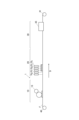
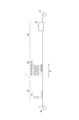
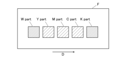
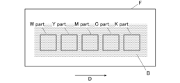
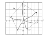
- Schematic diagram of a recording device preferred for the present invention Schematic diagram of the image forming device when the processing liquid is applied with a roll coater Schematic diagram when ink is applied on processing liquid Schematic diagram when inkjet coating of treatment liquid Schematic diagram of treatment liquid application pattern 1 Schematic diagram of treatment liquid application pattern 2 Schematic diagram of treatment liquid application pattern 3 Image forming device when using ink containing metal nanoparticles Schematic diagram of treatment liquid application pattern 4 Schematic diagram of treatment liquid application pattern 5 Schematic diagram for evaluating the wrinkling of printed materials An example of a gradation pattern image of a density gradation chart Example of color gamut evaluation using a * b * plane
- the image forming method of the present invention includes a treatment liquid application step, an ink application step, and a drying step.
- an ink containing a pigment, inorganic particles or organic particles, and a solvent is applied, and in at least one of the drying steps,
- the method is characterized by drying the coating film by irradiating it with microwaves.
- the treatment liquid by an inkjet method from the viewpoint of freely controlling the amount and application range of the treatment liquid.
- the treatment liquid contains a metal salt, a cationic resin, or an organic acid from the viewpoint of cohesion and fixing properties of the ink.
- the electrical conductivity of the treatment liquid is equal to or higher than the electrical conductivity of the ink, in order to improve the drying properties of the mixed coating film, form uniform dots without graininess, and improve gloss and color gamut.
- the treatment liquid contains a water-soluble solvent with a boiling point of 180° C. or higher from the viewpoint of controlling drying properties.
- the treatment liquid or the ink contain an ionic resin from the viewpoint of fixing properties, film forming properties, etc.
- the electrical conductivity of the mixed coating film of the treatment liquid and the ink be within the range of 50 to 600 mS/m from the viewpoint of preventing excessive printing and suppressing cracking and ignition of the mixed coating film.
- the drying step it is preferable to apply hot air to the mixed coating film of the treatment liquid and the ink from the viewpoint of controlling the drying properties of the mixed coating film.
- the base material has a portion that is deformed by heat, from the viewpoint of providing excellent design and 3D printing effects.
- the image forming apparatus of the present invention is characterized by using means for implementing the image forming method of the present invention. Thereby, the effects of the present invention can be realized and the problems can be solved.
- ⁇ is used to include the numerical values described before and after it as a lower limit value and an upper limit value.
- the image forming method of the present invention includes a treatment liquid application step, an ink application step, and a drying step.
- an ink containing a pigment, inorganic particles or organic particles, and a solvent is applied, and at least one of the drying steps is performed.
- the drying process is characterized by drying the coating film by irradiating it with microwaves.
- the concepts of "coating film” and “mixed coating film” include immediately after the treatment liquid is applied on the substrate, immediately after the ink is applied on the substrate, or This includes a liquid state with fluidity such as wetting and spreading properties or permeability immediately after the treatment liquid and the ink are mixed on the substrate, and a subsequent state (state after drying).
- liquid state with fluidity refers to a state in which a liquid (including a semi-solid state in the present invention) moves so as to spread or permeate the base material or coating. It means that.
- Treatment liquid application step (1.1.1) Treatment liquid The treatment liquid according to the present invention is used to apply ink onto a substrate in order to play the role of fixing (pinning) the ink on the recording medium.
- the treatment liquid can be applied before the ink is applied to the substrate, the treatment liquid can also be applied after the ink is applied to the substrate.
- the processing liquid plays a role in fixing (pinning) ink on a recording medium
- the processing liquid is applied onto the substrate before applying the ink, and after drying, the processing liquid is applied onto the substrate.
- an ink cohesive layer is formed.
- ink can be applied before the treatment liquid according to the present invention dries, in which case the ink uniformly coagulates and thickens.
- the ink can be properly wetted and spread, and the amount of pigment applied in the applied ink dots can be adjusted to an appropriate amount. Therefore, the dot diameter of the ink becomes an appropriate size, and it is possible to prevent insufficient filling of the ink in the print, unintended color mixture, and white streaks during image formation.
- the treatment liquid according to the present invention contains a material that is dissolved in water and has ionic properties.
- materials that dissolve in water and have ionic properties include ionic resins, metal salts, surfactants, organic acids, and inorganic acids.
- the electrical conductivity of the processing liquid can be changed by combining these materials, so the heating effect of the microwaves can be controlled, and the processing
- the dry pinning effect of microwaves is superimposed, making it possible to form images with less graininess and higher gloss and color gamut.
- it is suitable for uniform drying control.
- since a base material that does not absorb microwaves does not generate heat, there is no damage to the base material.
- the treatment liquid contains a metal salt, a cationic resin, or an organic acid from the viewpoint of cohesion and fixing properties of the ink.
- the processing liquid reacts and increases its viscosity, which acts as a coagulant, so even if images are formed on non-absorbent substrates, high image quality can be achieved. images can be formed. Moreover, these can be contained singly or in combination of two or more kinds.
- the processing liquid according to the present invention may contain a resin, which can improve the fixing property to the recording medium, such as vinyl chloride resin, (meth)acrylic resin, urethane resin, polyether resin, etc. and polyester-based resins, but it is preferable that the treatment liquid contains an ionic resin from the viewpoint of fixing properties, film-forming properties, and the like.
- a resin which can improve the fixing property to the recording medium
- the treatment liquid contains an ionic resin from the viewpoint of fixing properties, film-forming properties, and the like.
- the resin contained in the treatment liquid according to the present invention may be water-soluble, and since the pigment is usually an anionic component, it is a cationic resin, and when mixed with the ink, it forms an ink aggregation layer. It is preferable from the viewpoint of forming a mixed coating film.
- Cationic resins are also called cationic resins, and their hydrophilic groups become cationic when dissolved in water.
- Examples of the cationic resin include cationic urethane resins, cationic olefin resins, and cationic amine resins.
- cationic urethane resin commercially available products can be used, such as Hydran (registered trademark) CP-7010, CP-7020, CP-7030, CP-7040, CP-7050, CP-7060, CP-761037.
- Hydran registered trademark
- CP-7010 CP-7010
- CP-7020 CP-7020
- CP-7030 CP-7040
- CP-7050 CP-7060
- CP-761037 CP-761037.
- Superflex registered trademark
- 600, 610, 620, 630, 640, 650 Product name, manufactured by Dai-ichi Kogyo Seiyaku Co., Ltd.
- Urethane Emulsion WBR-2120C, WBR- 2122C trade name, manufactured by Taisei Fine Chemical Co., Ltd.
- the cationic olefin resin is a resin having an olefin such as ethylene or propylene in its structural skeleton, and known resins can be appropriately selected and used. Further, the cationic olefin resin may be in the form of an emulsion in which it is dispersed in a solvent containing water, an organic solvent, or the like. As the cationic olefin resin, commercially available products can be used, such as Arrowbase (registered trademark) CB-1200 and CD-1200 (trade name, manufactured by Unitika Co., Ltd.).
- the cationic amine-based resin may be one having an amino group in its structure, and known resins can be appropriately selected and used. Examples include polyamine resins having amino groups in the main skeleton of the resin, polyamide resins having amide groups in the main skeleton of the resin, polyallylamine resins having allyl groups in the main skeleton of the resin, and the like.
- cationic polyamine resin commercial products can be used, such as Unisense KHE103L (trade name, manufactured by Senka Co., Ltd., hexamethylene diamine/epichlorohydrin resin, 1% aqueous solution, pH approximately 5.0, viscosity 20 to 50 (mPa). ⁇ s), aqueous solution with a solid content concentration of 50% by mass), Unisense KHE104L (trade name, manufactured by Senka, dimethylamine/epichlorohydrin resin, 1% aqueous solution pH approximately 7.0, viscosity 1 to 10 (mPa s), (aqueous solution with a solid content concentration of 20% by mass), and the like.
- Unisense KHE103L trade name, manufactured by Senka Co., Ltd., hexamethylene diamine/epichlorohydrin resin, 1% aqueous solution, pH approximately 5.0, viscosity 20 to 50 (mPa). ⁇ s), aqueous solution with a solid content concentration of 50% by mass
- FL-14 (trade name, manufactured by SNF), ARAFIX (registered trademark) 100, 251S, 255, 255LOX (trade name, manufactured by Arakawa Chemical Co., Ltd.), DK-6810, 6853, 6885; WS-4010, 4011 , 4020, 4024, 4027, 4030 (trade name, manufactured by Seiko PMC), Papiogen (registered trademark) P-105 (trade name, manufactured by Senka), Sumirezu Resin 650 (3830), 675A, 6615, SLX-1 (Product name, manufactured by Taoka Chemical Industry Co., Ltd.), Catiomaster (registered trademark) PD-1, 7, 30, A, PDT-2, PE-10, PE-30, DT-EH, EPA-SK01, TMHMDA-E (trade name, manufactured by Yokkaichi Gosei Co., Ltd.), Jetfix 36N, 38A, and 5052 (trade name, manufactured by Satoda Kako Co.,
- polyallylamine resins examples include polyallylamine hydrochloride, polyallylamine amide sulfate, allylamine hydrochloride/diallylamine hydrochloride copolymer, allylamine acetate/diallylamine acetate copolymer, allylamine acetate/diallylamine acetate copolymer, and allylamine hydrochloride/diallylamine acetate copolymer.
- a free type polyallylamine resin that is not neutralized with an acid other than the above-mentioned acid salt type may be used.
- the free type is used in a processing liquid containing water, it is easier to adjust the pH of the processing liquid from neutral to alkaline, and it is effective against durability and corrosion of inkjet recording device components. This is preferred because it is advantageous.
- free type polyallylamine resins include PAA-01, PAA-03, PAA-05, PAA-08, PAA-15, PAA-15C, and PAA-25 (trade name, manufactured by Nitto Bo Medical Co., Ltd.). .
- the content of the cationic resin is preferably within the range of 1 to 5% by mass based on the total mass of the treatment liquid.
- the treatment liquid according to the present invention preferably contains an inorganic or organic polyvalent metal salt as the metal salt. Anionic components aggregate due to salting out.
- the polyvalent metal salt a salt of a metal having a valence of two or more can be used.
- the type of metal (cation) constituting the polyvalent metal salt is not particularly limited, but includes, for example, divalent metal ions such as Ca 2+ , Cu 2+ , Ni 2+ , Mg 2+ , Zn 2+ , Ba 2+ , Al 3+ , Fe 3+ , Examples include trivalent metal ions such as Cr 3+ and Y 3+ and tetravalent metal ions such as Zr 4+ .
- the type of salt constituting the polyvalent metal salt is not particularly limited, but known salts such as carbonates, sulfates, nitrates, hydrochlorides, organic acid salts, borates, and phosphates can be used.
- Specific examples of particularly preferred polyvalent metal salts include calcium or magnesium salts of carboxylic acids such as calcium chloride, magnesium chloride, calcium nitrate, magnesium nitrate, magnesium acetate, calcium acetate, magnesium lactate, and calcium pantothenate. Can be mentioned.
- the content of the polyvalent metal salt is preferably in the range of 0.5 to 20% by mass, more preferably in the range of 1 to 10% by mass, based on 100% by mass of the total mass of the treatment liquid.
- the content of a metal salt such as a polyvalent metal salt in an aqueous solution can be measured by a known method, such as ICP (inductively coupled plasma) emission spectrometry.
- ICP inductively coupled plasma
- metal salts other than polyvalent metal salts include monovalent metal salts such as sodium salts and potassium salts, such as sodium sulfate and potassium sulfate.
- the content of the metal salt is preferably 5% by mass or less, more preferably 0.1 to 3% by mass, and 0.5 to 1.0% by mass based on the total mass of the treatment liquid. It is more preferable that the amount is within the range of % by mass. By being within the above range, anionic components such as coloring materials in the ink can be effectively aggregated, so that both image quality and hot water resistance can be achieved.
- the amount of metal salt applied is within the range of 0.1 to 20 g/m 2 , and the amount of the treatment liquid applied should be adjusted so that it is within the above range. is preferred.
- the organic acid according to the present invention is capable of aggregating pigments that may be contained in the ink.
- the treatment liquid contains the organic acid as a flocculant
- the anionic components in the ink can be flocculated by pH fluctuation.
- the organic acid is preferably a monovalent carboxylic acid from the viewpoint of not weakening the cohesive force of the polyvalent metal salt.
- organic acids examples include formic acid, malonic acid, acetic acid, propionic acid, isobutyric acid, and benzoic acid.
- not completely neutralized means that among the acidic groups of the organic acid, there are acidic groups that are not completely neutralized and dissociate protons (H + ) by a base. means.
- the storage stability of the treatment liquid is easily maintained, and blocking is less likely to occur after the treatment liquid is applied and dried.
- preferred organic acids include formic acid, malonic acid, acetic acid, propionic acid, and benzoic acid.
- the content of the organic acid is preferably within the range of 0.1 to 10% by mass, and more preferably within the range of 1 to 3% by mass, based on 100% by mass of the total mass of the treatment liquid. preferable.
- the amount of organic acid applied is preferably an amount that adjusts the pH of the treatment liquid to a value equal to or less than the neutralization equivalent of the anion component contained in the ink.
- the anion component is a compound having a carboxyl group
- the first dissociation constant of the organic acid is preferably 3.5 or less from the viewpoint of making the image less likely to bleed.
- the content of the organic acid in the aqueous solution can be measured by a known method, such as high performance liquid chromatography (HPLC).
- HPLC high performance liquid chromatography
- Acids other than organic acids include inorganic acids, such as sulfuric acid, hydrochloric acid, nitric acid, and phosphoric acid. These may be used alone or in combination of two or more.
- the acid content is preferably 5% by mass or less, more preferably 0.1 to 3% by mass, and 0.5 to 1.0% by mass based on the total mass of the treatment liquid. It is more preferably within the range of %. By being within the above range, anionic components such as white pigments in the ink can be effectively agglomerated, so that both image quality and hot water resistance can be achieved.
- the acid content can be measured by a known method such as high performance liquid chromatography (HPLC).
- the amount of acid applied is preferably equal to or less than the neutralization equivalent of the anion component in the ink, and the amount of the treatment liquid applied is adjusted so that it is within the above range. It is preferable to do so.
- the treatment liquid according to the present invention can contain, as a solvent, a water-soluble solvent with a boiling point within the range of 150 to 250°C, and when the treatment liquid contains a solvent with a high boiling point as described above, Since the treatment liquid becomes difficult to evaporate, drying performance can be lowered, which is preferable from the viewpoint of uniform drying performance control.
- water-soluble solvents mentioned above include alcohols, polyhydric alcohols, amines, amides, glycol ethers, and 1,2-alkanediols having 4 or more carbon atoms. It is preferable to contain a water-soluble solvent having a temperature of 180° C. or higher from the viewpoint of controlling drying properties.
- the drying rate of a specific location can be slowed down. It is suitable for uniform drying control.
- polyhydric alcohols having 2 to 8 carbon atoms examples include 1,2-ethanediol, 1,2-propanediol, 1,3-propanediol, 1,2-butanediol, 1,3-butanediol, 1, 4-butanediol, 2,3-butanediol, 2-methyl-1,3-propanediol, 1,2-pentanediol, 1,5-pentanediol, 1,2-hexanediol, 1,6-hexanediol , 2-methylpentane-2,4-diol and the like.
- polyalkylene glycols examples include diethylene glycol, dipropylene glycol, and the like.
- the treatment liquid may contain one or a combination of two or more selected from these water-soluble solvents.
- At least one water-soluble solvent having a boiling point in the range of 150 to 250°C is contained in the ink, including alcohols other than those mentioned above, polyhydric alcohols, amines, amides, glycol ethers, carbon number may contain 1,2-alkanediols in which is 4 or more.
- the total content of the water-soluble solvent is preferably in the range of 5 to 40% by mass, more preferably in the range of 10 to 40% by mass, based on 100% by mass of the total mass of the treatment liquid.
- the treatment liquid according to the present invention can also contain, as a solvent, a non-water-soluble solvent other than a water-soluble solvent having a boiling point within the range of 150 to 250°C.
- a non-water-soluble solvent other than a water-soluble solvent having a boiling point within the range of 150 to 250°C. Examples include trimethylolpropane, triethylene glycol, and tetraethylene glycol.
- the treatment liquid according to the present invention preferably contains a surfactant.
- the surfactant is not particularly limited, but preferably at least one selected from the group consisting of polysiloxane surfactants and acetylene glycol surfactants.
- polysiloxane surfactants are more preferred because their solubility in the processing liquid is increased and foreign matter is less likely to be generated in the processing liquid.
- polysiloxane surfactants include, but are not limited to, TEGOWET-KL245 (polyether-modified siloxane copolymer; manufactured by Evonik Co., Ltd.), BYK-347 (manufactured by BYK-Chemie Co., Ltd.), and BYK-348 (manufactured by BYK-Chemie Co., Ltd.).
- BYK-349 manufactured by BYK-CHEMIE Corporation
- BYK-3550 manufactured by BYK-CHEMIE Corporation
- BYK-UV3510 manufactured by BYK-CHEMIE Corporation
- acetylene glycol surfactants include, but are not limited to, 2,4,7,9-tetramethyl-5-decyne-4,7-diol and 2,4,7,9-tetramethyl-5 - selected from alkylene oxide adducts of decyne-4,7-diol and alkylene oxide adducts of 2,4-dimethyl-5-decyn-4-ol and 2,4-dimethyl-5-decyn-4-ol. One or more of these are preferred.
- E series such as Olfine 104 series and Olfine E1010 (manufactured by Air Products Japan, Inc.), Olfine PD-002W, Surfynol 465 and Surfynol 61 (manufactured by Nissin Chemical Industry). CO., Ltd.) and other commercially available products.
- the content of the above-mentioned surfactant is preferably within the range of 0.1 to 10% by mass based on 100% by mass of the total mass of the reaction solution.
- the treatment liquid according to the present invention may contain a surfactant, water, a crosslinking agent, a fungicide, a bactericide, and other components as appropriate within a range that does not impair the effects of the present invention.
- Various known additives such as antistatic agents, preservatives, thickeners, and antistatic agents can also be included.
- the processing liquid will be more susceptible to the heating effect of microwaves than the ink. Therefore, in the image forming method of the present invention, quick drying properties can be imparted to areas where drying properties are desired to be improved, so that uniform drying properties can be controlled. Further, it is preferable because the influence of microwaves can be controlled in accordance with the ink-applied area for areas where ink is not applied.
- the electrical conductivity can be easily measured by the method described in JIS K 0130 (1995).
- a specific method for measuring electrical conductivity for example, in an environment where the measurement temperature is 20°C, the treatment liquid is placed in a measurement cell (CT-58101B manufactured by Toa DKK Co., Ltd.), and a measuring device (CM-31P manufactured by Toa DKK Co., Ltd.) is used. It can be measured by
- the physical properties of the treatment liquid according to the present invention are not particularly limited and can be appropriately selected depending on the purpose.
- the viscosity, surface tension, pH, etc. are preferably within the following ranges.
- the viscosity of the treatment liquid at 25° C. is preferably within the range of 5 to 30 mPa ⁇ s, and preferably within the range of 5 to 25 mPa ⁇ s, from the viewpoint of obtaining good ejection stability from the nozzle of the inkjet head. It is more preferable.
- the viscosity was measured using, for example, a rotational viscometer "RE-80L” manufactured by Toki Sangyo Co., Ltd., and the measurement conditions were 25°C, a standard cone rotor (1°34' x R24), and a sample liquid volume of 1. Measurement can be performed at 2 mL, rotation speed of 50 rpm, and 3 minutes.
- the surface tension of the treatment liquid is preferably within the range of 1 to 55 mN/m, and 1 to 40 mN at 25°C, from the viewpoint of suitably leveling the ink on the recording medium and shortening the drying time of the ink. /m or less is more preferable, and even more preferably within the range of 1 to 35 mN/m.
- the surface tension can be measured by the Wilhelmy method using a surface tension meter "CBVP-Z" manufactured by Kyowa Interface Science Co., Ltd. or the like.
- Treatment liquid application method In the treatment liquid application step according to the present invention, a treatment liquid containing an ionic material dissolved in water and a solvent is applied onto a substrate. It is preferable to apply the ink so that the treatment liquid and the ink are mixed in liquid form on the substrate from the viewpoints of appropriate aggregation of the ink, prevention of uneven aggregation, and improvement of the pinning property of the ink.
- the method of applying the treatment liquid onto the substrate is not particularly limited, but preferable examples include an inkjet method, a roller coating method, a curtain coating method, and a spray coating method. It is preferable to apply the liquid by an inkjet method from the viewpoint of freely controlling the amount and application range of the treatment liquid.
- the amount and application range of the treatment liquid can be freely controlled depending on the type of substrate and variations in dryness. Since the surface of the substrate can be controlled evenly within the surface of the substrate and dried more evenly within the surface of the substrate, problems such as wobbling do not occur in the image (printed material).
- the base material to be used is a metal base material
- the metal base material is placed on a conveyor belt, and a treatment liquid layer is applied and formed while the belt is conveying, or the base material is fixed. It is also preferable to use a flatbed type printer for forming the treatment liquid layer.
- the inkjet method is not particularly limited, and a printer equipped with an inkjet head loaded with a treatment liquid can be used.
- the treatment liquid can be ejected as droplets from the nozzles of the inkjet head based on a digital signal, and the droplets can be caused to land on the recording medium to apply the treatment liquid.
- the apparatus used for the inkjet method will be described in detail in the description of the image forming apparatus.
- the ink according to the present invention is characterized by containing a pigment, inorganic particles or organic particles, and a solvent, and includes an ionic resin, a surfactant, It may contain water and other ingredients. Further, the ink according to the present invention preferably contains a pigment dispersant for dispersing the pigment. It is preferable to use two or more types of ink having different electrical conductivities from the viewpoint of controlling the drying properties of the ink.
- “having different electrical conductivity” refers to ink with low electrical conductivity that is close to insulation, such as yellow ink (Y), magenta ink (M), and cyan ink (C), and black ink with low electrical conductivity. This refers to the difference from inks with high electrical conductivity, such as ink (K) and white ink (W). Specifically, a case where the difference in electrical conductivity between one ink and the other ink is 5 or more is defined as "the electrical conductivities are different.”
- the higher the electrical conductivity of microwaves the greater the heat generation effect, so the amount of processing liquid applied is appropriate depending on the amount of applied ink with low electrical conductivity and the amount of applied ink with high electrical conductivity.
- the ink having high electrical conductivity is not dried excessively, uniform drying control can be performed, and high-quality printed matter can be obtained.
- the pigments contained in the ink of the present invention include anionic dispersed pigments, such as self-dispersing pigments having anionic groups on the surface, pigments dispersed with an anionic polymer dispersant, and pigments with anionic dispersion on the surface.
- anionic dispersed pigments such as self-dispersing pigments having anionic groups on the surface
- pigments dispersed with an anionic polymer dispersant Preferably, pigments coated and dispersed with a resin are used.
- a pigment dispersed with an anionic polymer dispersant because it has excellent dispersibility and the processing liquid and pigment react appropriately to cause pinning.
- pigments conventionally known pigments can be used without particular limitation, and for example, inorganic pigments containing inorganic particles such as titanium oxide, insoluble pigments, and organic pigments containing organic particles such as lake pigments can be preferably used.
- insoluble pigment examples include, but are not limited to, azo, azomethine, methine, diphenylmethane, triphenylmethane, quinacridone, anthraquinone, perylene, indigo, quinophthalone, isoindolinone, isoindoline, azine, oxazine, thiazine, and dioxazine. , thiazole, phthalocyanine, diketopyrrolopyrrole and the like are preferred.
- Organic pigment Specific organic pigments that can be preferably used include the following pigments.
- pigments for magenta or red examples include C. I. Pigment Red 2, C. I. Pigment Red 3, C. I. Pigment Red 5, C. I. Pigment Red 6, C. I. Pigment Red 7, C. I. Pigment Red 15, C. I. Pigment Red 16, C. I. Pigment Red 48:1, C.I. I. Pigment Red 53:1, C.I. I. Pigment Red 57:1, C.I. I. Pigment Red 122, C. I. Pigment Red 123, C. I. Pigment Red 139, C. I. Pigment Red 144, C. I. Pigment Red 149, C. I. Pigment Red 166, C. I. Pigment Red 177, C. I. Pigment Red 178, C. I. Pigment Red 202, C. I. Pigment Red 222, C. I. Pigment Violet 19 and the like.
- pigments for orange or yellow examples include C.I. I. Pigment Orange 31, C. I. Pigment Orange 43, C. I. Pigment Yellow 12, C. I. Pigment Yellow 13, C. I. Pigment Yellow 14, C. I. Pigment Yellow 15, C. I. Pigment Yellow 15:3, C.I. I. Pigment Yellow 17, C. I. Pigment Yellow 74, C. I. Pigment Yellow 93, C. I. Pigment Yellow 128, C. I. Pigment Yellow 94, C. I. Pigment Yellow 138, C. I. Pigment Yellow 155 and the like. Especially in the balance of color tone and light resistance, C. I. Pigment Yellow 155 is preferred.
- green or cyan pigments examples include C.I. I. Pigment Blue 15, C. I. Pigment Blue 15:2, C. I. Pigment Blue 15:3, C. I. Pigment Blue 16, C. I. Pigment Blue 60, C. I. Pigment Green 7 and the like.
- pigment for black for example, C.I. I. Pigment Black 1, C. I. Pigment Black 6, C. I. Pigment Black 7 and the like.
- inorganic pigments of various colors can be used.
- an inorganic pigment as the white pigment.
- the white pigment is not particularly limited as long as it is a pigment that makes a cured film formed by curing the ink containing the white pigment appear white.
- white pigments include titanium oxide, zinc oxide, zinc sulfide, calcium carbonate, calcium silicate, barium sulfate, aluminum hydroxide, antimony oxide, zirconium oxide, silicas such as finely divided silicic acid and synthetic silicates, and talc. , clay, etc.
- white metal oxides are preferred, and titanium oxide is more preferred. These may be used alone or in combination of two or more.
- the present invention can particularly suitably prevent bleeding and improve adhesion.
- Titanium oxide has three crystal forms: anatase type, rutile type, and brookite type, but the general-purpose types can be roughly divided into anatase type and rutile type.
- a rutile type having a large refractive index and high hiding power is preferable. Specific examples include the TR series from Fuji Titanium Industries Co., Ltd., the JR series from Teika Co., Ltd., and the Taipeiku from Ishihara Sangyo Co., Ltd.
- the ink according to the present invention preferably contains a pigment dispersant for dispersing the pigment.
- the pigment dispersant is not particularly limited, but a polymer dispersant having an anionic group is preferable, and one having a molecular weight in the range of 5,000 to 200,000 can be suitably used.
- polymer dispersant examples include two types selected from styrene, styrene derivatives, vinylnaphthalene derivatives, acrylic acid, acrylic acid derivatives, maleic acid, maleic acid derivatives, itaconic acid, itaconic acid derivatives, fumaric acid, and fumaric acid derivatives.
- examples include block copolymers, random copolymers, and salts thereof having structures derived from the above monomers, polyoxyalkylenes, polyoxyalkylene alkyl ethers, and the like.
- the polymer dispersant preferably has an acryloyl group, and is preferably added after being neutralized with a neutralizing base.
- a neutralizing base is not particularly limited, it is preferably an organic base such as ammonia, monoethanolamine, diethanolamine, triethanolamine, or morpholine.
- the pigment is titanium oxide
- it is preferable that the titanium oxide is dispersed with a polymer dispersant having an acryloyl group.
- the amount of the polymer dispersant added is preferably within the range of 10 to 100% by mass, more preferably within the range of 10 to 40% by mass, based on the pigment.
- the pigment has the form of a so-called capsule pigment in which the pigment is coated with the above-mentioned polymeric dispersant.
- a polymeric dispersant such as phase inversion emulsification, acid precipitation, or dispersing the pigment with a polymerizable surfactant and coating
- Preferred examples include a method of supplying a monomer and coating while polymerizing it.
- a particularly preferred method is to dissolve a water-insoluble resin in an organic solvent such as methyl ethyl ketone, partially or completely neutralize the acidic groups in the resin with a base, and then add pigment and ion-exchanged water to disperse the resin. Thereafter, the organic solvent may be removed, and if necessary, water may be added.
- an organic solvent such as methyl ethyl ketone
- the average particle size of the dispersed pigment in the ink is preferably 50 nm or more and less than 200 nm. Thereby, the dispersion stability of the pigment can be improved, and the storage stability of the ink can be improved.
- the particle size of pigments can be measured using commercially available particle size measuring instruments using dynamic light scattering, electrophoresis, etc., but measurement using dynamic light scattering is simple and allows the particle size to be measured within the particle size range. Can be measured accurately.
- the pigment can be used by being dispersed with a dispersing machine together with a dispersant and other necessary additives depending on the desired purpose.
- the dispersing machine conventionally known ball mills, sand mills, line mills, high-pressure homogenizers, etc. can be used. Among these, it is preferable to disperse the pigment using a sand mill because the particle size distribution becomes sharp.
- the material of the beads used for sand mill dispersion is not particularly limited, but from the viewpoint of preventing the generation of bead fragments and contamination of ionic components, zirconia or zircon is preferable.
- the bead diameter is preferably within the range of 0.3 to 3 mm.
- the content of the pigment in the ink is not particularly limited, but for titanium oxide it is preferably within the range of 7 to 18% by mass, and for the organic pigment it is preferably within the range of 0.5 to 7% by mass.
- the inorganic particles or organic particles contained in the ink according to the present invention are used as an inorganic pigment or an organic pigment, for example, by being included in a pigment.
- the solvent the same solvent as the above-mentioned processing liquid can be used.
- Inorganic particles that can be used in the present invention include, for example, light calcium carbonate, heavy calcium carbonate, magnesium carbonate, kaolin, clay, talc, calcium sulfate, barium sulfate, titanium dioxide, zinc oxide, zinc hydroxide, zinc sulfide, Zinc carbonate, hydrotalcite, aluminum silicate, diatomaceous earth, calcium silicate, magnesium silicate, synthetic amorphous silica, colloidal silica, alumina, colloidal alumina, pseudoboehmite, aluminum hydroxide, lithopone, zeolite, magnesium hydroxide
- white inorganic pigments such as.
- inorganic particles contained in ink include titanium oxide, but it is difficult to ensure ink ejection stability and adhesion with titanium oxide, and due to its high electrical conductivity, it is difficult to use titanium oxide during the drying process described below. is greatly affected by the heat generation effect of microwaves.
- the heating effect caused by microwaves can be appropriately controlled by appropriately controlling the applied amount of the treatment liquid described above, so that the above-mentioned drawbacks of titanium oxide can be compensated for.
- Organic particles are water-insoluble organic particles that dissolve or swell in a water-soluble organic solvent with a boiling point of 120° C. or higher, and their materials include, for example, polyvinyl chloride, polyvinylidene chloride, polyacrylate, and polymethacrylate.
- elastomer ethylene-vinyl acetate copolymer, styrene-(meth)acrylic copolymer, polyester, polyvinyl ether, polyvinyl acetal, polyamide, polyurethane, polyolefin, SBR, NBR, polytetrafluoroethylene, chloroprene, protein, polysaccharide , rosin ester, shellac resin and the like.
- Particularly preferable materials for the organic particles include polyvinyl acetal resin, polyurethane resin, rosin ester resin, (meth)acrylate resin, SBR, etc.
- Resins made of two or more monomers can also be used by modification or copolymerization.
- it may be a resin with a specific modification group added or a leaving group removed, or two or more materials may be mixed to form organic particles, and two or more materials may be formed.
- a mixture of organic particles may be used.
- dissolution refers to the organic particles and the water-soluble organic solvent in the ink forming a single phase in an equilibrium state
- swelling refers to the organic particles absorbing the same water-soluble organic solvent. It means to increase the volume.
- the organic particles according to the present invention must be insoluble in water so that they do not dissolve during inkjet recording. However, it is permissible to absorb water to the extent that it does not impede the ink absorption speed. Up to 20% by weight of water, based on the weight of the organic particles, may be absorbed.
- a crosslinking agent may be used in the organic particles according to the present invention insofar as it does not interfere with dissolution or swelling in a water-soluble organic solvent.
- any conventionally known crosslinking agent whether organic or inorganic, can be appropriately selected and used as the crosslinking agent.
- the organic particles themselves are preferably hydrophilic but not water-soluble, the content is preferably adjusted to a range of 10% by mass or more to less than 50% by mass.
- the glass transition temperature (Tg) of the organic particles according to the embodiment described in [1-4] above needs to be 70°C or higher, preferably 80°C or higher, and more preferably 90°C or higher. It is within the range of 120°C.
- the glass transition temperature (Tg) of the organic particles is less than 70°C, the organic particles tend to fuse together due to heating, and as a result, the voids on the surface of the recording paper shrink or decrease, reducing the ink absorption speed. becomes more likely to occur.
- the ink according to the present invention may contain a resin, which can improve fixation to the recording medium, such as vinyl chloride resin, (meth)acrylic resin, urethane resin, polyether resin, etc.
- a resin which can improve fixation to the recording medium
- examples include resins, polyester resins, etc., but it is preferable that the ink contains an ionic resin from the viewpoint of fixing properties, film forming properties, etc.
- the ionic resin is directly heated by the microwaves, so that film forming properties and adhesion to the substrate are improved.
- the ionic resin contained in the ink of the present invention is preferably water-insoluble resin particles, and the glass transition temperature (Tg [°C]) of the resin particles is preferably within the range of 40 to 90°C. preferable.
- the glass transition temperature is determined from the endothermic peak of the glass when the temperature is raised at a heating rate of 10°C/min in a temperature range of -30 to 200°C using a DSC (differential scanning calorimeter). It can be identified by reading the transition temperature (Tg [° C.]).
- the water-insoluble resin preferably used in the present invention is a water-insoluble resin that can accept ink and exhibits solubility or affinity for the ink.
- the "water-insoluble resin fine particles" used in the present invention are originally water-insoluble, but have a form in which the resin is dispersed in an aqueous medium as microscopic particles, and can be forcibly emulsified using an emulsifier or the like and placed in water.
- Dispersed water-insoluble resins, or self-emulsifiable non-aqueous resins that form stable water dispersions by themselves without the use of emulsifiers or dispersion stabilizers by introducing hydrophilic functional groups into their molecules. It is a synthetic resin.
- These resins are usually used in a state where they are emulsified and dispersed in water or a water/alcohol mixed solvent.
- water-insoluble means that when the resin is dried at 105°C for 2 hours and then dissolved in 100g of water at 25°C, the dissolved amount is 10g or less, preferably 5g or less, and It refers to a resin whose weight is preferably 1 g or less.
- the amount dissolved is the amount dissolved when the salt-forming group of the resin is 100% neutralized with acetic acid or sodium hydroxide, depending on the type.
- the resin having a glass transition temperature within the range of 40 to 90°C is preferably an acrylic resin, a urethane resin, a polyester resin, or a composite resin of a urethane resin and an acrylic resin, particularly an acrylic resin, a urethane resin, It is a composite resin of polyester resin or urethane resin and acrylic resin, and it is preferable that the average particle size of these resin particles is 200 nm or less. In particular, the average particle size is preferably within a range of 100 to 150 nm.
- polyester resin, urethane resin, acrylic resin, or composite resin fine particles of urethane resin and acrylic resin are preferably anionic.
- the resin fine particles contained in the ink preferably contain an acid structure, and even if the amount of surfactant added is small, it can be dispersed in water, and the water resistance of the mixed coating film is improved. .
- This is called a self-emulsifying type, which means that the resin can be dispersed and stabilized in water using only molecular ionicity without using a surfactant.
- Examples of acid structures include acid groups such as carboxy groups (-COOH) and sulfonic acid groups (-SO 3 H).
- the acid structure may be present in the side chain or at the end of the resin. It is particularly preferable that the ink according to the present invention contains a water-dispersible polyester resin having a sulfonic acid group. As a result, high adhesion to the base material can be obtained.
- part or all of the acid structure is neutralized. By neutralizing the acid structure, the water dispersibility of the resin can be improved.
- Examples of the neutralizing agent that neutralizes the acid structure include organic amines, and it is preferable to use organic amines such as trimethylamine, triethylamine, tripropylamine, tributylamine, N-methyldiethanolamine, and triethanolamine.
- the ink according to the present invention preferably contains resin fine particles having a cohesiveness of 0.2 or less with a 0.15 mass % calcium acetate aqueous solution within a range of 3 to 15 mass %.
- the value of "cohesiveness” is a value calculated by the following formula after measuring the remaining amount according to the following procedure.
- Cohesiveness 1 - (mass of solid content [g] / (mass of collected supernatant liquid [g] x 5 [%])
- Examples of the resin fine particles having an aggregation property of 0.2 or less include Vylonal MD2000 manufactured by Toyobo Co., Ltd., Movinyl 6969D manufactured by Japan Coating Resin Co., Ltd., and Evaphanol HA-560 manufactured by Nicca Chemical Co., Ltd., and the like.
- a polyester resin having a polyester skeleton used as water-insoluble resin particles can be obtained by using a polyhydric alcohol component and a polycarboxylic acid component such as a polycarboxylic acid, a polycarboxylic acid anhydride, or a polycarboxylic acid ester. I can do it.
- the polyhydric alcohol component includes dihydric alcohols (diols), specifically alkylene glycols having 2 to 36 carbon atoms (ethylene glycol, 1,2-propylene glycol, 1,3-propylene glycol, 1 , 4-butylene glycol, 1,6-hexanediol, etc.), alkylene ether glycols having a carbon number of 4 to 36 (diethylene glycol, triethylene glycol, dipropylene glycol, polyethylene glycol, polypropylene glycol, polybutylene glycol, etc.), Alicyclic diols having 6 to 36 carbon atoms (1,4-cyclohexanedimethanol, hydrogenated bisphenol A, etc.), alkylene oxides (ethylene oxide (hereinafter referred to as ethylene oxide) having 2 to 4 carbon atoms), , EO), propylene oxide (hereinafter abbreviated as PO), butylene oxide (hereinafter abbreviated as BO)) adducts (in the range of 1 to
- the polyhydric carboxylic acid component includes dicarboxylic acids (dicarboxylic acids), specifically alkanedicarboxylic acids having 4 to 36 carbon atoms (succinic acid, apidic acid, sebacic acid, etc.), alkenylsuccinic acids, etc.
- dicarboxylic acids with a carbon number of 4 to 36 (dimer acid (dimerized linoleic acid), etc.), alkene dicarboxylic acids with a carbon number of 4 to 36 (maleic acid, fumaric acid, etc.) , citraconic acid, mesaconic acid, etc.), or aromatic dicarboxylic acids having 8 to 36 carbon atoms (phthalic acid, isophthalic acid, terephthalic acid or derivatives thereof, naphthalene dicarboxylic acid, etc.). These may be used alone or in combination of two or more.
- polyester resin a polyester resin having an anionic group in the molecule is preferable, and a polyester resin containing a sulfonic acid group is particularly preferable.
- polyesters containing sulfonic acid groups include, for example, polycondensation reactions between dicarboxylic acids having sulfonic acid groups and diols, and polyesters containing dicarboxylic acids and diols containing sulfonic acid salts. It can also be obtained by a method such as a polycondensation reaction.
- Examples of the dicarboxylic acid component having a sulfonic acid group include 2-sulfoterephthalic acid, 5-sulfoisophthalic acid, 4-sulfonaphthaleneisophthalic acid-2,7-dicarboxylic acid, and 5-(4-sulfophenoxy)isophthalic acid; Examples include alkali metal salts thereof.
- diol having a sulfonic acid group examples include 2-sulfo-1,4-butanediol, 2,5-dimethyl-3-sulfo-2,5-hexanediol, and alkali metal salts thereof.
- the number average molecular weight of the polyester resin is preferably within the range of 1,000 to 50,000, more preferably within the range of 2,000 to 20,000.
- polyester resin commercially available products may be used.
- examples of commercially available water-dispersible polyester resins having sulfonic acid groups include Vylonal MD-1100, MD-1200, MD-1245, and MD- manufactured by Toyobo Co., Ltd. 1480, MD-1500, MD-2000, Plus Coat Z-221, Z-446, Z-561, Z-880, Z-3310, manufactured by Gooh Kagaku Co., Ltd., Pesresin A-520, A-613D, A manufactured by Takamatsu Yushi Co., Ltd. -615GE, A-640, A-645GH, A-647GEX, A-110F, A-160P, etc.
- resins with a glass transition temperature within the range of 40 to 90°C are particularly preferable, such as Vylonal MD-1100, MD-1200, MD-1245, MD-1500, MD-2000 manufactured by Toyobo Co., Ltd., Plus manufactured by Gooh Kagaku Co., Ltd. Coat Z-221, Z-446, Z-561, Pesresin A-520, A-613D, A-615GE, A-640, A-645GH, A-647GEX manufactured by Takamatsu Yushi Co., Ltd., and the like. These may be used alone or in combination of two or more.
- urethane resin As the urethane resin used as the water-insoluble resin particles according to the present invention, one having a hydrophilic group can be used.
- the above-mentioned urethane resin is either an aqueous dispersion in which a self-emulsifying urethane having a water-soluble functional group, that is, a hydrophilic group, is dispersed in its molecule, or a forced emulsion in which the resin is emulsified under strong mechanical shearing force using a surfactant.
- a self-emulsifying urethane having a water-soluble functional group that is, a hydrophilic group
- a forced emulsion in which the resin is emulsified under strong mechanical shearing force using a surfactant.
- a surfactant Preferably, it is an aqueous dispersion of type urethane.
- the urethane resin in the aqueous dispersion can be obtained by reacting a polyol with an organic polyisocyanate and a hydrophilic group-containing compound.
- polyester polyols include ethylene glycol, diethylene glycol, triethylene glycol, 1,2- and 1,3-propylene glycol, neopentyl glycol, 1,3- and 1,4-butanediol, 3-methylpentanediol, Low molecular polyols such as hexamethylene glycol, 1,8-octanediol, 2-methyl-1,3-propanediol, bisphenol A, hydrogenated bisphenol A, trimethylolpropane, cyclohexanedimethanol; succinic acid, glutaric acid, adipine Acids, including condensates with polycarboxylic acids such as sebacic acid, phthalic acid, isophthalic acid, terephthalic acid, trimellitic acid, tetrahydrofuranic acid, endomethinetetrahydrofuranic acid, and hexahydrophthalic acid.
- Low molecular polyols such as hexamethylene glycol
- polyether polyols examples include polyethylene glycol, polypropylene glycol, polyethylene polytetramethylene glycol, polypropylene polytettremethylene glycol, and polytetramethylene glycol.
- polycarbonate polyols can be obtained by reacting a carbonic acid derivative such as diphenyl carbonate, dimethyl carbonate or phosgene with a diol.
- diols examples include ethylene glycol, diethylene glycol, triethylene glycol, 1,2- and 1,3-propylene glycol, neopentyl glycol, 1,3- and 1,4-butanediol, 3-methylpentanediol, These include hexamethylene glycol, 1,8-octanediol, 2-methyl-1,3-propanediol, bisphenol A, hydrogenated bisphenol A, trimethylolpropane, and cyclohexanedimethanol.
- organic polyisocyanates examples include tolylene diisocyanate (TDI), diphenylmethane diisocyanate (MDI), polymeric MDI, xylylene diisocyanate (XDI), and tetramethylxylylene diisocyanate.
- TDI tolylene diisocyanate
- MDI diphenylmethane diisocyanate
- XDI polymeric MDI
- XDI xylylene diisocyanate
- TMXDI tetramethylxylylene diisocyanate
- aliphatic isocyanates such as hexamethylene diisocyanate (HMDI)
- alicyclic isocyanates such as isophorone diisocyanate (IPDI) and 4,4'-dicyclohexylmethane diisocyanate (hydrogenated MDI, H12MDI). It will be done. These may be used alone or in combination of two or more.
- taurine i.e., aminoethyl sulfonic acid
- ethoxypolyethylene glycol sulfonic acid ethoxypolyethylene glycol sulfonic acid
- Urethane resin can be obtained by a known method.
- a urethane prepolymer can be obtained by mixing the above-mentioned polyol, organic polyisocyanate, and a hydrophilic group-containing compound and reacting the mixture at a temperature of 30 to 130°C for 30 minutes to 50 hours.
- the above-mentioned urethane prepolymer becomes a urethane resin having hydrophilic groups by being extended with a chain extender and polymerized.
- the chain extender is preferably water and/or an amine compound.
- water or an amine compound as a chain extender, it is possible to react with free isocyanate in a short time and efficiently extend the isocyanate-terminated prepolymer.
- amine compounds as chain extenders include aliphatic polyamines such as ethylenediamine and triethylenediamine; aromatic polyamines such as metaxylene diamine and tolylene diamine; polyhydrazino compounds such as hydrazine and adipic acid dihydrazide.
- the amine compound may contain a monovalent amine such as dibutylamine, methyl ethyl ketoxime, etc. as a reaction terminator to the extent that polymerization is not significantly inhibited.
- a monovalent amine such as dibutylamine, methyl ethyl ketoxime, etc.
- a solvent that is inert with the isocyanate and capable of dissolving the urethane prepolymer may be used.
- solvents examples include dioxane, methyl ethyl ketone, dimethyl formamide, tetrahydrofuran, N-methyl-2-pyrrolidone, toluene, propylene glycol monomethyl ether acetate, and the like. These hydrophilic organic solvents used in the reaction step are preferably finally removed.
- amine catalysts e.g. triethylamine, N-ethylmorpholine, triethyldiamine, etc.
- tin catalysts e.g. dibutyltin dilaurate, dioctyltin dilaurate, tin octylate, etc.
- titanium-based catalyst e.g, tetrabutyl titanate, etc.
- the number average molecular weight of the urethane resin is preferably made as large as possible by introducing a branched structure or internal crosslinked structure, and the number average molecular weight is preferably within the range of 50,000 to 1,000,000.
- the number average molecular weight (Mn) is a value measured by gel permeation chromatography (GPC), for example, "RID-6A” manufactured by Shimadzu Corporation (column: “TSK-GEL” manufactured by Tosoh Corporation, solvent : Tetrahydrofuran (THF), column temperature: 40°C), and can be determined from a calibration curve prepared with a polystyrene standard sample.
- GPC gel permeation chromatography
- urethane resin a commercially available product may be used as the urethane resin.
- examples of commercial products in which the glass transition temperature of the urethane resin is within the range of 40 to 90°C include Neorez R-967, R-600, and R-9671 manufactured by Kusumoto Kasei Co., Ltd., and Evafanol HA- manufactured by NICCA Chemical Co., Ltd. 560, SF870 manufactured by Daiichi Kogyo Seiyaku Co., Ltd., and the like.
- the acrylic resin used as the water-insoluble resin particles can be obtained by using a copolymer with an acrylic ester component, a methacrylic ester component, a styrene component, or the like.
- acrylic ester components and methacrylic ester components include methyl (meth)acrylate, ethyl (meth)acrylate, propyl (meth)acrylate, butyl (meth)acrylate, and 2-(meth)acrylate.
- styrene component examples include styrene, 4-methylstyrene, 4-hydroxystyrene, 4-acetoxystyrene, 4-acetylstyrene, styrene sulfonic acid, and the like. These components may be used alone or in combination of two or more.
- the number average molecular weight (Mn) of the acrylic resin is preferably within the range of 1,000 to 50,000, more preferably within the range of 2,000 to 20,000.
- the number average molecular weight (Mn) of the acrylic resin is 1,000 or more, the cohesive force of the coating film is strong and the adhesion is improved, and when it is 50,000 or less, the solubility in organic solvents is good and the emulsified dispersion is This is because miniaturization of particle size is promoted.
- the number average molecular weight (Mn) is a value measured by gel permeation chromatography (GPC), for example, "RID-6A” manufactured by Shimadzu Corporation (column: “TSK-GEL” manufactured by Tosoh Corporation, solvent : Tetrahydrofuran (THF), column temperature: 40°C), and can be determined from a calibration curve prepared with a polystyrene standard sample.
- GPC gel permeation chromatography
- acrylic resin a commercially available product may be used as the acrylic resin.
- acrylic resins whose glass transition temperature is within the range of 40 to 90°C include Movinyl 6899D, 6969D, and 6800 manufactured by Japan Coating Resin Co., Ltd., and TOCRYL W-7146, W-7147, and W-7148 manufactured by Toyochem Co., Ltd. , W-7149, W-7150, and other acrylic emulsions.
- the composite resin fine particles that can be contained in the ink are preferably composite resin fine particles formed by emulsifying an acrylic resin with a urethane resin. That is, it is preferable that the composite resin particles have an inner layer made of acrylic resin and a surface layer made of urethane resin.
- the urethane resin exists at the interface between the acrylic resin as the water-insoluble resin particles and water as the continuous phase, and functions as a water-insoluble resin particle layer different from the resin that protects the water-insoluble resin particles.
- the physical properties of the image (coating film) can be improved compared to emulsifying and mixing acrylic resin and urethane resin respectively. It is possible to improve the storage stability of the composite resin fine particles.
- the mass ratio value (U/A) of the urethane resin (U) and the acrylic resin (A) is from 40/60 to 95/5. is preferred.
- the proportion of the acrylic resin (A) is within the above range, the adhesiveness to the acrylic film is excellent.
- the mass ratio value (U/A) of urethane resin (U) and acrylic resin (A) is preferably within the range of 40/60 to 80/20.
- the total resin concentration of the acrylic resin and urethane resin in the composite resin fine particles is not particularly limited, but is preferably 5.0% by mass or more, and within the range of 10.0 to 70.0% by mass. It is more preferable that there be. When the resin concentration is within the above range, the fixability of the ink to the recording medium will be good.
- a surfactant that acts as an emulsifier can be used together with the urethane resin.
- the storage stability of the composite resin fine particles can be improved.
- Anionic surfactants and nonionic surfactants can be used as the emulsifier.
- the average particle size of the composite resin fine particles is not particularly limited, but is preferably within the range of 10 to 500 nm, more preferably within the range of 10 to 300 nm, and preferably within the range of 10 to 200 nm. More preferred.
- the average particle size can be measured using a commercially available particle size measuring device using dynamic light scattering, electrophoresis, etc., but measurement using dynamic light scattering is simple and allows you to measure the particle size in the relevant particle size range. Can be measured accurately.
- the ink according to the present invention may contain various known additives depending on other purposes such as ejection stability, compatibility with print heads and ink cartridges, storage stability, and image storage stability.
- the ink according to the present invention may contain a pH adjuster, a surfactant, a crosslinking agent, a fungicide, a bactericidal agent, and other components as appropriate.
- additives examples include surfactants. By adding a surfactant, it is possible to improve the ejection stability of ink and control the spread (dot diameter) of ink droplets that have landed on a recording medium.
- the surfactant is not particularly limited, but if the ink contains an anionic compound, the ionicity of the surfactant may be anionic, nonionic (also referred to as "nonionic"), or amphoteric.
- the zwitterionic surfactant is preferably of the betaine type.
- the surfactant is preferably nonionic because if the anionic surfactant contains an alkaline component, the resin fine particles included as the fixing resin will tend to aggregate and the fixing performance will decrease.
- surfactants include fluorine-based or silicone-based surfactants that have a high ability to lower static surface tension, anionic surfactants such as dioctyl sulfosuccinate that have a high ability to lower dynamic surface tension, and relatively Nonionic surfactants such as low molecular weight polyoxyethylene alkyl ethers, polyoxyethylene alkylphenyl ethers, acetylene glycols, Pluronic (registered trademark) type surfactants, and sorbitan derivatives are preferred.
- a surfactant with a high static surface tension lowering ability and a surfactant with a high dynamic surface tension lowering ability may be used in combination.
- the electrical conductivity of the processing liquid is equal to or higher than the electrical conductivity of the ink, since this improves the drying properties of the processing liquid and forms uniform dots without graininess, thereby improving gloss and color gamut. If the electrical conductivity of the processing liquid is greater than or equal to the electrical conductivity of the ink, when drying with microwaves is performed in the drying step described below, the processing liquid will be more susceptible to the heating effect of microwaves than the ink. As a result, the processing liquid dries before the ink. Therefore, in the image forming method of the present invention, it is possible to impart quick drying properties to areas where drying properties should be improved, so uniform drying properties can be controlled.
- the physical properties of the ink of the present invention are not particularly limited and can be appropriately selected depending on the purpose.
- the viscosity, surface tension, pH, etc. are preferably within the following ranges.
- the viscosity of the ink at 25° C. is preferably within the range of 5 to 30 mPa ⁇ s from the viewpoint of improving print density and character quality and obtaining good ejection stability from the nozzle of the inkjet head. More preferably, it is within the range of 5 to 25 mPa ⁇ s.
- the viscosity is measured using, for example, a rotational viscometer "RE-80L” manufactured by Toki Sangyo Co., Ltd., and the measurement conditions are 25°C, a standard cone rotor (1°34' x R24), and a sample liquid volume of 1. .2 mL, rotation speed 50 rpm, and 3 minutes.
- the surface tension of the ink is preferably within the range of 1 to 55 mN/m, and 1 to 40 mN/m at 25°C, from the viewpoint of suitably leveling the ink on the recording medium and shortening the drying time of the ink. It is more preferably less than m, and even more preferably within the range of 1 to 35 mN/m.
- the surface tension can be measured by the Wilhelmy method using a surface tension meter "CBVP-Z” manufactured by Kyowa Interface Science Co., Ltd. or the like.
- the pH value of the ink is preferably within the range of 3 to 9, more preferably within the range of 6 to 9.
- the method of applying the ink onto the treatment liquid is not particularly limited as in the case of the treatment liquid described above, but application by an inkjet method is preferable from the viewpoint of controlling the uniformity and density of the ink. It is preferable to apply the treatment liquid and the ink so that they are mixed in liquid form on the substrate from the viewpoint of suppressing uneven aggregation of the ink and pinning property of the ink.
- liquid refers to a state in which the drying rate of the processing liquid and ink is 30% or less.
- the treatment liquid applied onto the base material may be heated and dried, but it is preferable that the treatment liquid and the ink are mixed in a liquid state, In the heating and drying described above, it is preferable to apply the ink while the drying rate of the treatment liquid is 30% or less. If the ink is applied in a state where the drying rate of the treatment liquid is greater than 30%, the treatment liquid and the ink may be in liquid form and not mix.
- the ink it is preferable to apply the ink within 10 seconds after applying the treatment liquid. In particular, it is preferable that the ink is applied within 0.1 to 5 seconds after the treatment liquid is applied, and the drying rate of the treatment liquid is within the range of 1 to 10%.
- drying rate of the treatment liquid is defined by the following formula.
- the ink By applying the ink in a state where the drying rate of the treatment liquid is 30% or less, diffusion of the ink occurs and wettability is improved.
- the treatment liquid can penetrate into the absorbent substrate and the treatment liquid can be applied to the non-absorbent substrate. Suppresses repellency and achieves higher image quality.
- the time after application of the treatment liquid until the application of the ink may be adjusted, the temperature of the recording medium may be appropriately adjusted, etc. It will be done.
- the amount of the ink applied (also referred to as the "application amount") is within a range of 2 to 25 times the amount of the treatment liquid applied per unit area of the recording medium. It is preferable to adjust the amount of ink droplets in such a way that higher image quality can be achieved, and the more preferable range of the applied amount is 3 to 10 times.
- the drying process according to the present invention is performed between the treatment liquid application process and the ink application process, between the ink application process and the treatment liquid process, and after the treatment liquid application process and the ink application process.
- Microwaves can be applied at any time between the coating process and the ink coating process, during the processing liquid coating process, ink coating process, etc. However, from the viewpoint of equipment load and image quality, it is recommended to use microwaves after the processing liquid coating process and the ink coating process. It is preferable to dry it all at once in a drying process that includes.
- Microwaves have high directivity and can prevent the nozzle from drying during inkjet coating, for example, so it is possible to dry the nozzle immediately after printing without worrying about the nozzle drying. Furthermore, when the treatment liquid contains a metal salt or the like, the aggregation effect is enhanced and the durability and fastness are improved.
- the coating film is dried by irradiating microwaves in at least one of the drying steps as described above.
- microwave drying conditions of the present invention are as follows. Although a microwave generator manufactured by Shimada Rika Kogyo Co., Ltd. is used under the following conditions, a commercially available microwave dryer such as a batch type microwave dryer manufactured by Yamamoto Vinita Co., Ltd. may also be used.
- Microwave generator ESG-2450S-2A Manufactured by Shimada Rika Kogyo Co., Ltd.
- non-contact heating type drying equipment such as a drying oven or hot air blower may be used, or a drying device such as a hot plate or a hot roller may be used.
- the drying may be carried out using a contact heating type drying device such as the above.
- the above heating temperature is preferably within the range of 60 to 200°C, and the heating time is appropriately adjusted depending on the type of substrate, the amount of the treatment liquid applied, and the amount of ink applied.
- the drying temperature is (a) when using a non-contact heating type drying device such as a drying oven or hot air blower, the ambient temperature such as the oven temperature or hot air temperature, and (b) the temperature of the hot plate or hot roller.
- a non-contact heating type drying device such as a drying oven or hot air blower
- the ambient temperature such as the oven temperature or hot air temperature
- the temperature of the hot plate or hot roller When using a contact heating type drying device such as the It is more preferable to measure the surface temperature of the surface to be dried (c) as the measurement location.
- the solvent components of the treatment liquid and the ink are removed, and at the same time, especially in the case of metal substrates, polyvalent metal salts are heated. It decomposes thermally by drying at a temperature above the decomposition temperature. In addition, the image abrasion resistance and adhesion to the substrate are improved.
- the temperature of the hot air used for drying control is preferably in the range of 80 to 100°C, and the wind speed is preferably in the range of 5 to 40 m/s.
- the above-mentioned mixed coating film of processing liquid and ink is dried by microwave, hot air and other drying methods. It is preferable that the electrical conductivity of the mixed ink coating film be within the range of 50 to 600 mS/m from the viewpoint of preventing excessive printing and suppressing cracking and ignition of the mixed coating film.
- drying rate of the mixed coating film of the treatment liquid and the ink is defined by the following formula.
- the thickness of the mixed coating film obtained as described above is preferably within the range of 0.3 to 3.0 ⁇ m, More preferably, it is within the range of 0.3 to 2.0 ⁇ m.
- the thickness of the mixed coating film is 0.3 ⁇ m or more, it is easy to improve the adhesion and abrasion resistance of the image. Further, when the thickness of the mixed coating film is 3.0 ⁇ m or less, the deformation stress applied to the ink layer can be reduced, so that the adhesion of the image is less likely to be impaired.
- Base material It is preferable that the base material has a portion that is deformed by heat, from the viewpoint of providing excellent design and 3D printing effects.
- the temperature range of the above heat varies depending on the material of the part of the base material that is deformed by heat, but for example, if the base material has a foam layer containing a foam material with an expansion start temperature within the range of 100 to 200 °C, It is within the range of ⁇ 50°C of the expansion start temperature.
- the treatment liquid is applied onto the substrate (recording medium) by, for example, an inkjet method.
- the applicable recording medium is not particularly limited, and may be an absorbent base material made of an absorbent material or a non-absorbent base material made of a non-absorbent material.
- the base material is a non-absorbent base material.
- absorbency refers to the ability to absorb water
- non-absorbency refers to the non-absorption ability to water
- non-absorbent base material a known plastic film can be used.
- plastic films include polyester films such as polyethylene terephthalate, polyethylene films, polypropylene films, polyamide films such as nylon, polystyrene films, polyvinyl chloride films, polycarbonate films, polyacrylonitrile films, and polylactic acid films.
- polyester films such as polyethylene terephthalate, polyethylene films, polypropylene films, polyamide films such as nylon, polystyrene films, polyvinyl chloride films, polycarbonate films, polyacrylonitrile films, and polylactic acid films.
- biodegradable films such as .
- films coated with polyvinylidene chloride on one or both sides, or films coated with metal oxides can also be preferably used.
- the non-absorbent film can be preferably used as either an unstretched film or a stretched film.
- the thickness of the base material is preferably within the range of 10 to 120 ⁇ m, more preferably within the range of 12 to 60 ⁇ m.
- metal substrates such as tin plates and tin-free steel plates (TFS plates, thickness 0.1 to 0.6 ⁇ m) for three-piece cans are also preferably used as non-absorbent substrates, such as thermosetting resins. It can be suitably used for packaging materials for canned foods, etc., which are provided as a coating layer.
- the packaging materials for canned foods for example, block air, moisture, and light and seal the food inside, so epoxy-phenol paint or polyester laminating agent is used on the food side, and polyester-based laminating agent is used on the outside.
- epoxy-phenol paint or polyester laminating agent is used on the food side
- polyester-based laminating agent is used on the outside.
- acrylic thermosetting paints are used.
- the image forming apparatus of the present invention is an image forming apparatus having a treatment liquid application step, an ink application step, and a drying step, and is characterized by having means for implementing the image forming method of the present invention. shall be.
- the effects of the present invention can be exhibited, and an image forming method can be provided that has excellent gloss and color gamut, as well as excellent pinning properties and substrate adhesion.
- FIG. 1 is a schematic diagram of a recording device preferred for the present invention.
- the present invention is not limited to this.
- the recording apparatus 1 mainly includes a treatment liquid application section 10 and an ink application section 20.
- the treatment liquid 12 is applied onto the base material F.
- the coating film of the treatment liquid formed on the area C to which the treatment liquid has been applied may be partially dried, if necessary.
- the treatment liquid application section 10 is not particularly limited as long as it has a configuration that can apply the treatment liquid to the substrate, but in the present invention, the treatment liquid application method may be an inkjet method using the inkjet head 11. Preferable from the viewpoint of drying control.
- the ink 22 is applied to a desired range on the treatment liquid 12.
- the ink application section 20 is not particularly limited as long as it can apply ink to the coating film of the treatment liquid formed in the region C on the substrate where the treatment liquid is applied.
- the coating method is preferably an inkjet method using an inkjet head 21 from the viewpoint of drying control.
- the mixed region CR is formed by applying the treatment liquid onto the base material F before the ink, but in a configuration other than that shown in FIG.
- the mixed region CR may be formed by applying the mixture on top.
- a microwave drying device M irradiates a desired portion with microwaves, and if necessary, the drying section 33 heats and dries the mixed coating film of the treatment liquid and ink.
- a treatment liquid 12 is applied by an inkjet head 11 onto a base material F fed out from a feed roller 40, an ink 22 is applied by an inkjet head 21 onto the treatment liquid 12, and a micro
- the wave drying section 30 heats and dries the area to which the treatment liquid and ink have been applied, thereby forming a mixed coating film of the treatment liquid and ink. Thereafter, the base material F on which the above mixed coating film is formed is wound up by the winding roller 41 to obtain an image recording material.
- FIG. 1 shows the case where the base material F is a film base material
- the metal base material is placed on a conveyor belt, and the above mixed coating film is applied while conveying the belt. can be applied and formed in one pass.
- a flatbed type printer for applying the treatment liquid and ink.
- the base material is fixed and the inkjet head can be moved in the main scanning direction and the sub-scanning direction that crosses the main scanning direction, making it possible to print without transporting the base material. It is.
- Metal substrates such as tin cannot be conveyed roll-to-roll like resin film materials, so it is preferable to use a flatbed type printer that does not require conveying the substrate.
- Examples of such flatbed type printers include the printers shown in FIG. 1 of JP-A No. 2015-74161 and FIG. 1 of JP-A No. 2017-177578.
- the inkjet head may be either an on-demand type inkjet head or a continuous type inkjet head.
- on-demand inkjet heads include electro-mechanical conversion types including single cavity, double cavity, bender, piston, shear mode and shared wall types, as well as thermal inkjet and bubble jet ( "Bubble jet” includes electrical-to-thermal conversion methods, including the type (registered trademark of Canon Corporation).
- an inkjet head using a piezoelectric element as an electromechanical conversion element used in an electromechanical conversion method (also referred to as a piezo type inkjet head) is preferable.
- a single-pass type inkjet printer which may be either a scan type inkjet head or a single-pass type inkjet head
- a line head type inkjet head refers to an inkjet head that has a length that is greater than the width of the printing range (processing liquid application range).
- a line head type inkjet head As a line head type inkjet head, a single head with a width greater than or equal to the printing range (processing liquid application range) may be used, or a combination of multiple heads may be used to cover the width of the printing range (processing liquid application range).
- the configuration may be configured as described above.
- a plurality of heads may be arranged in parallel so that their nozzles are arranged in a staggered manner to increase the resolution of these heads as a whole.
- the conveyance speed of the recording medium which is the base material, can be set within a range of, for example, 1 to 120 m/min. The faster the conveyance speed is, the faster the image forming speed is.
- A. Preparation of treatment liquid (A.1) Preparation of treatment liquid [1] 3.00% by mass of calcium acetate monohydrate as a flocculant, 12.00% by mass of dipropylene glycol (DPG) as a solvent, propylene glycol (PG) ) (1,2-HDO) 20.00% by mass, "TEGOWET-KL245" (polyether-modified siloxane copolymer; manufactured by Evonik) 1.00% by mass as a surfactant, "Proxel GXL (S)” as a fungicide.
- DPG dipropylene glycol
- PG propylene glycol
- TEGOWET-KL245" polyether-modified siloxane copolymer; manufactured by Evonik
- the electrical conductivity of the treatment liquid [1] was measured using the method described above and found to be 659 mS/m.
- TEGOWET "TEGOWET-KL245" (polyether modified siloxane copolymer; manufactured by Evonik)
- B. Preparation of pigment dispersion liquid to be included in each ink (B.1) Preparation of white pigment dispersion liquid [W] Pigment dispersion in 40% by mass of white pigment (titanium oxide CR-50-2; manufactured by Ishihara Sangyo Co., Ltd.) as a pigment.
- “Joncryl 819” anionic polymer dispersant, dimethylaminoethanol neutralized acrylic dispersant having a carboxy group, acid value 75 [mgKOH/g], solid content 20% by mass, manufactured by BASF) 4 mass %
- “Disperbyk-2019” solvent-free wetting and dispersing agent manufactured by Byk Chemie
- PG propylene glycol
- Proxel 1,2-benzisothiazolin-3-one
- a white pigment dispersion [W] having a pigment content of 20% by mass was prepared by dispersing using a bead mill filled with 0.3 mm zirconia beads at a volume ratio of 50%.
- the average particle size of the pigment particles contained in this pigment dispersion was 250 nm.
- the average particle diameter was measured using "Zetasizer Nano S-90" manufactured by Mulballoon.
- magenta pigment dispersion [M] The type of pigment was magenta pigment (mixed crystal of Pigment Red 122 and Pigment Violet 19), and 8% by mass of only “Joncryl 819” was added as a pigment dispersant.
- a magenta pigment dispersion [M] having a pigment content of 20% by mass was prepared in the same manner as the white pigment dispersion [W] except for the above.
- the average particle size of the pigment particles contained in this pigment dispersion was 250 nm. Note that the average particle diameter was measured using "Zetasizer Nano S-90" manufactured by Mulballoon.
- the average particle diameter of the pigment particles contained in these pigment dispersions was all 250 nm. Note that the average particle diameter was measured using "Zetasizer Nano S-90" manufactured by Mulballoon.
- the particles were dispersed using a bead mill filled with 0.3 mm zirconia beads at a volume ratio of 50% to prepare a silver nanoparticle dispersion [Ag] with a pigment content of 20% by mass.
- the average particle size of the pigment particles contained in this pigment dispersion was 250 nm. Note that the average particle diameter was measured using "Zetasizer Nano S-90" manufactured by Mulballoon.
- C. Ink preparation and ink set (C.1) Ink set [1] (Preparation of white ink [W ink 1]) 20.00% by mass of white pigment dispersion [W] as a pigment dispersion, 5.00% by mass of Vylonal MD2000 (polyester resin, glass transition temperature Tg of resin only: 67°C, manufactured by Toyobo Co., Ltd.) as a resin fine particle dispersion, and a solvent.
- Yellow ink [W ink 1] was prepared in the same manner as white ink [W ink 1] except that the pigment dispersion liquid, resin fine particle dispersion liquid, solvent, type of surfactant, type and amount of antifungal agent and water were changed as shown in Table II.
- Y ink 1] magenta ink [M ink 1], cyan ink [C ink 1], and black ink [K ink 1] were prepared.
- An ink set is prepared by combining the white ink [W ink 1], yellow ink [Y ink 1], magenta ink [M ink 1], cyan ink [C ink 1], and black ink [K ink 1] prepared above. 1] was prepared.
- (C.2) Ink set [2] (Preparation of white ink [W ink 2] 20.00% by mass of white pigment dispersion [W] as a pigment dispersion, and Superflex 460 (polyurethane water dispersion manufactured by Daiichi Kogyo Seiyaku Co., Ltd.) as a resin fine particle dispersion.5. 00% by mass, 25.00% by mass of propylene glycol (PG) as a solvent, 3.00% by mass of glycerin (Gly), 1.00% by mass of "TEGOWET-KL245" (polyether modified siloxane copolymer; manufactured by Evonik) as a surfactant.
- PG propylene glycol
- Gly glycerin
- TEGOWET-KL245" polyether modified siloxane copolymer; manufactured by Evonik
- Yellow ink [W ink 2] was prepared in the same manner as white ink [W ink 2] except that the pigment dispersion liquid, resin fine particle dispersion liquid, solvent, type of surfactant, type and amount of antifungal agent and water were changed as shown in Table II.
- Y ink 2] magenta ink [M ink 2], cyan ink [C ink 2], and black ink [K ink 2] were prepared.
- An ink set is prepared by combining the white ink [W ink 2], yellow ink [Y ink 2], magenta ink [M ink 2], cyan ink [C ink 2], and black ink [K ink 2] prepared above. 2] was prepared.
- Yellow ink [W ink 3] was prepared in the same manner as white ink [W ink 3] except that the pigment dispersion liquid, resin fine particle dispersion liquid, solvent, type of surfactant, type and amount of antifungal agent and water were changed as shown in Table II.
- Y ink 3] magenta ink [M ink 3], cyan ink [C ink 3], and black ink [K ink 3] were prepared.
- Ink combination of ink set [3] White ink [W ink 3], yellow ink [Y ink 3], magenta ink [M ink 3], cyan ink [C ink 3], black ink [K ink 3], and silver nanoparticle-containing ink prepared above.
- Ink set [3] was prepared by combining [Ag ink 3].
- TEGOWET "TEGOWET-KL245" (polyether modified siloxane copolymer; manufactured by Evonik)
- the treatment liquid [1] was applied to the entire surface of the substrate using a roll coater 15.
- the treatment liquid was applied using the roll coater at a speed of 400 mm/s and a coating amount of 3.0 g/m 2 .
- each ink [W ink 1 ], [ Y ink 1 ] , [M ink 1], [C ink 1], [K ink 1]) are inked in a square shape of 5 cm x 5 cm with a width of 5 mm on the W part , Y part , M part , C part and K part of Fig. 3.
- Inkjet coating was performed at an applied amount of 12.0 g/m 2 to form a mixed coating film of the treatment liquid and ink.
- microwave drying section 30 microwave processing is performed in a drying device 35 to dry the printed matter No. 1 was produced.
- the above microwave treatment was performed under the following conditions.
- Hot air treatment was performed at a temperature of 70° C. and a wind speed of 16 m/sec.
- the treatment liquid [1] was applied using the inkjet head H1 at a liquid volume of 6 pL and a maximum printing rate of 37%, and the amount of treatment liquid applied in the application area was 3.0 g/m 2 . It was applied all over the base material.
- each ink [W ink 1 ], [ Y ink 1 ] , [M ink 1], [C ink 1], [K ink 1]) are inked in a square shape of 5 cm x 5 cm with a width of 5 mm on the W part , Y part , M part , C part and K part of Fig. 3.
- Inkjet coating was performed at an applied amount of 12.0 g/m 2 to form a mixed coating film of the treatment liquid and ink.
- microwave drying section 30 microwave processing is performed in a drying device 35 to dry the printed matter No. 9 was produced.
- the above microwave treatment was performed under the following conditions.
- treatment liquid [1] is applied at 1.0 g/m 2 to the W part and K part as shown in FIG. 5A (pattern 1), and 6.0 g/m 2 is applied to the Y part , M part , and C part . / m2 was applied and 3.0g/ m2 was applied to the area other than the ink-applied area.
- Print No. Printed matter No. 9 is printed in the same manner as in 9. 10 were produced.
- the method of applying the treatment liquid in Example 10 is referred to as Pattern 1 of the treatment liquid patterns in Table III.
- Print No. Preparation of 11 In the drying process, print No. 1 was subjected to microwave treatment in the drying device and then hot air treatment. Printed matter No. 10 is printed using the same procedure as 10. 11 was produced. Regarding the hot air treatment conditions, refer to Print No. The test was carried out under the same conditions as in step 2.
- treatment liquid [1] is applied at 1.0 g/m 2 to the W part and K part as shown in FIG. 5B (pattern 2), and 6.0 g/m 2 is applied to the Y part , M part , and C part . /m 2 was applied, and the processing liquid [1] was not applied to the area other than the ink-applied area.
- Printed matter No. 9 is printed in the same manner as in 9. 12 were produced.
- the method of applying the treatment liquid in No. 12 is referred to as Pattern 2 of the treatment liquid patterns in Table III.
- Print No. Preparation of 13 In the treatment liquid application step, print No. 1 was used except that treatment liquid [2] was applied instead of treatment liquid [1]. Printed matter No. No. 13 was prepared.
- Print No. Preparation of 14 In the treatment liquid application step, print No. 1 was used except that treatment liquid [3] was applied instead of treatment liquid [1]. Printed matter No. 14 was produced.
- Print No. 1 except that ink set [2] is filled instead of ink set [1].
- Printed matter No. 10 is printed using the same procedure as 10. No. 15 was produced.
- treatment liquid [4] was applied at 6.0 g/m 2 to the W part and K part as shown in FIG. 5C, and at 1.0 g/m 2 to the Y part , M part , and C part .
- print No. 1 was used except that the treatment liquid [1] was not applied to the parts other than the ink-applied parts.
- Printed matter No. 9 is printed in the same manner as in 9. No. 16 was produced.
- the method of applying the treatment liquid in No. 16 is designated as pattern 3 of the treatment liquid patterns in Table III.
- the ink set [3] was filled so that the silver nanoparticle-containing ink [Ag ink 3] was ejected from the inkjet head H3.
- an inkjet head H1 and an inkjet head H2 were prepared for applying the treatment liquid.
- Treatment liquid application process In the treatment liquid application step, as shown in FIG. 5B (pattern 2), 1.0 g/m 2 is applied to the W part and K part , and 6.0 g/m 2 is applied to the Y part , M part , and C part , and at the same time, an inkjet Using head H2, treatment liquid [4] was applied to the portion E in FIG. 7 at a rate of 1.5 g/m 2 in a width of 3 cm.
- Ink application process In the ink application section 20, five inkjet heads (H w , H Y , H M , H C , H K ) ink each of the ink sets [3] except for the silver nanoparticle-containing ink [Ag ink 3]. Inks ([W ink 1], [Y ink 1], [M ink 1], [C ink 1], [K ink 1]) are inserted into W part , Y part , M part , C part and K part in FIG.
- a mixed coating film of the treatment liquid and ink was applied to the W part , Y part , and the ink coating by inkjet coating in a square shape of 5 cm x 5 cm with a width of 5 mm so that the amount of ink applied in the application area was 12.0 g/m 2 .
- the silver nanoparticle-containing ink [Ag ink 3] was applied from the inkjet head H3 to the M part , C part , and K part in a square shape of 5 cm x 5 cm with a width of 5 mm at the position shown in Fig. 7 in an amount of 12.0 g/ink.
- Inkjet coating was performed as m 2 to form a mixed coating film of the treatment liquid and silver nanoparticle-containing ink [Ag ink 3].
- microwave processing is performed in a drying device 35 to dry the printed matter No. 20 were produced.
- the above microwave treatment was performed under the following conditions.
- (F.4) Image forming method 4 (inkjet application of treatment liquid to foam layer) [Print No. Preparation of 21] Prints were created using the configuration of the image forming method as shown in FIG. 4, and the drawing performance was evaluated.
- the conveyance direction of the base material is the direction D in FIG. 4, and as the recording medium F, a coating liquid [21] having the following composition containing Sekisui Chemical's foamed particle Advance Cell is applied to a white PET base material ( The foam layer was coated on CRISPR K1211) to a thickness of 50 ⁇ m and dried in an oven at 80° C. for 10 minutes, thereby providing a base material with a foam layer.
- a scan printer equipped with five independently driven inkjet heads (360 npi, ejection volume 6 pL or 14 pL, 1024 nozzles) (H w , HY , HM , HC , HK ) manufactured by Konica Minolta was prepared, Ink set [1] was filled.
- an inkjet head H1 for applying the treatment liquid was prepared.
- Treatment liquid application process In the treatment liquid application section 10, the treatment liquid [1] was applied at 3.0 g/m 2 to the foam layer portion B of the base material having the foam layer using the inkjet head H1.
- each ink ([W ink 1 ], [ Y ink 1 ] , [M ink 1], [C ink 1], [K ink 1]) are inked in a square shape of 5 cm x 5 cm with a width of 5 mm on the W part , Y part , M part , C part and K part of Fig. 8.
- Inkjet coating was carried out at an applied amount of 12.0 g/m 2 to form a mixed coating film of the treatment liquid and ink on the foam layer portion B of the base material having the foam layer.
- microwave drying section 30 microwave processing is performed in a drying device 35 to dry the printed matter No. 21 was produced.
- the above microwave treatment was performed under the following conditions.
- ⁇ Gloss level 40 or higher.
- ⁇ Glossiness of 30 or more and less than 40.
- ⁇ Glossiness of 25 or more and less than 30.
- ⁇ The average value of the deviations in four spaces (5 mm) is 100 ⁇ m or less. Good: The average value of the deviations in four spaces (5 mm) is 200 ⁇ m or less. ⁇ : The average value of the deviations in four spaces (5 mm) is 300 ⁇ m or more.
- Japan Color refers to the color reproduction area (recommended value) in the L * a * b * color space defined by the "ISO-compliant Japan Color for Sheetfed Printing 2011", and is a * b as shown in Figure 10B. * Refers to the range indicated by the dotted line on the plane.
- color gamut is equal to or greater than Japan color
- “color gamut is equal to or greater than Japan color” means that the measured values obtained overlap with the shape of the Japan color formed by a broken line on the a * b * plane, or This refers to the case where measured values are plotted outside the shape.
- ⁇ Crosscut method> (1) Using a cutter guide, make 11 cuts on the test surface that reach the substrate, creating 100 base marks (the intervals between the cuts are 1 mm, 2 mm, and 5 mm). (2) Sellotape (registered trademark) is strongly pressed onto the base grain portion, the end of the tape is peeled off at once at an angle of 45°, and the condition of the base grain is evaluated by comparing it with a standard diagram.
- Sellotape registered trademark
- ⁇ No peeling due to tape.
- ⁇ There is peeling of 1 square or more but less than 3 squares of cut in a checkerboard pattern, but it is at a practically acceptable level.
- ⁇ There is some peeling in 3 squares or more and less than 6 squares of grid-like cuts, but it is at a good level.
- ⁇ Peeling of 6 squares or more with a checkerboard pattern, which is at a practically unacceptable level.
Landscapes
- Chemical & Material Sciences (AREA)
- Engineering & Computer Science (AREA)
- Wood Science & Technology (AREA)
- Life Sciences & Earth Sciences (AREA)
- Materials Engineering (AREA)
- Organic Chemistry (AREA)
- Toxicology (AREA)
- General Health & Medical Sciences (AREA)
- Health & Medical Sciences (AREA)
- Thermal Sciences (AREA)
- Physics & Mathematics (AREA)
- Quality & Reliability (AREA)
- Chemical Kinetics & Catalysis (AREA)
- Inks, Pencil-Leads, Or Crayons (AREA)
Abstract
Description
この方法によれば、前記非吸収性基材上に画像(印刷物)を形成する際に、凝集剤を含有する処理液を用いることでカラーインクが凝集し、その効果により光沢及び色域に優れ、ピニング性及び基材密着性に優れた良質な画像を形成することができる。
また、基材の種類によってはインクのピニング性が不足する問題があった。
上記の乾燥方法は、電気伝導度の高い材料にマイクロ波が直接作用するため、乾燥効率が高く、プラスチック基材等へダメージがないという利点があることが知られている。
しかしながら、定着樹脂及び凝集剤を含有する処理液とカラーインクとを含むインクセットを用いた画像形成時にマイクロ波を照射する旨の記載はなく、均一な乾燥性制御がされていないことに問題があった。
しかしながら、定着樹脂としてはウレタン樹脂のみを採用していることから樹脂選択の余地がせまく、凝集剤を含有する処理液とカラーインクとを含むインクセットを用いた画像形成時にマイクロ波を照射する旨の記載はなく、均一な乾燥性制御がされていないことに問題があった。
すなわち、本発明に係る上記課題は、以下の手段により解決される。
本発明の効果の発現機構ないし作用機構については、明確にはなっていないが、以下のように推察している。
処理液塗布工程において用いられる処理液は、通常、インクを適度に凝集させ、かつ凝集ムラ抑制及びインクのピニング性の向上等の目的・観点から用いられる。
これに加えて、本発明に係る処理液では、水に溶解してイオン性を有する材料及び溶媒が含有されていることにより当該処理液の電気伝導度が高くなるので、後にマイクロ波を照射すると、誘電加熱に加え塩イオンのジュール熱も加わり発熱効果が高くなり、乾燥工程における凝集速度が大きく向上する。
結果としてインクドットがより小さく、均一なdotを形成し、光沢や色域の高い画像が形成される。
すなわち、処理液とカラーインクの凝集ピニングの効果にマイクロ波乾燥を組み合わせることで、単なる乾燥性向上だけでない画質向上効果を得ることができる。
なお、処理液塗布工程とインク塗布工程の順序は限定されるものではなく、所望性能、効塗布効率等に応じて、適宜順序を変更することができる。
また、上記「流動性を有する液状の状態」とは、液体(本発明においては半固体状のものを含む。)が基材上又は塗膜上において濡れ拡がる又は浸透するように移動する状態のことをいうものとする。
ここでいう「均一な乾燥性制御」とは、ある特定の乾燥対象部分に速乾性を付与し、かつ、当該対象部分以外の部分とそうでない部分とを均一に乾燥させるようにコントロールすることをいう。
また、処理液とカラーインクにマイクロ波を適用することで、光沢や色域が広い画像を形成する効果は記載されていない。
本発明においては、処理液に含有されるイオン性を有する材料及び溶媒の性質や組合せ等により乾燥対象物の面内の電気伝導度差を小さくすることによってマイクロ波照射による発熱効果を均一に制御することができる。
上記のように均一な乾燥性制御が行えることでインクのピニング性に優れ、色域や基材密着性が向上し、透明性が高く、色域に優れた高画質な画像が形成できることを見出した。
この特徴は、下記各実施形態(態様)に共通する又は対応する技術的特徴である。
これによって、本発明の効果が発現し、課題を解決することができる。
本発明の画像形成方法は、処理液塗布工程と、インク塗布工程と、乾燥工程と、を有する画像形成方法であって、前記処理液塗布工程にて、基材上に水に溶解してイオン性を有する材料及び溶媒を含有する処理液を塗布し、前記インク塗布工程にて、顔料、無機粒子又は有機粒子及び溶媒を含有するインクを塗布し、前記乾燥工程のうち少なくとも一つの乾燥工程にて、マイクロ波を照射することにより塗膜を乾燥させることを特徴とする。
また、上記「流動性を有する液状の状態」とは、液体(本発明においては半固体状のものを含む。)が基材上又は塗膜上において濡れ拡がる又は浸透するように移動する状態のことをいうものとする。
(1.1.1)処理液
本発明に係る処理液は、インクを記録媒体上に固定(ピニング)する役割を担うためにインクが基材上に塗布される前に当該処理液を塗布することもできるが、当該インクが基材上に塗布された後に当該処理液を塗布することもできる。
また、本発明に係る処理液が乾燥する前にインクを付与することもでき、その場合はインクが均一に凝集及び増粘する。
本発明に係る処理液は、水に溶解してイオン性を有する材料を含有する。
水に溶解してイオン性を有する材料としては、イオン性を有する樹脂、金属塩、界面活性剤、有機酸、無機酸等を挙げることができる。
また、後述する乾燥工程にてマイクロ波による乾燥を行う際には、これらの材料の組み合わせによって処理液の電気伝導度を変えることができるため、マイクロ波の発熱効果を制御することができ、処理液とインクの凝集ピニング効果に加えて、マイクロ波による乾燥ピニング効果が重畳してより粒状性がなく光沢や色域の高い画像を形成できる。
また、均一な乾燥性制御に好適である。
さらには、マイクロ波を吸収しない基材は発熱しないため基材のダメージもない。
前記処理液が、前記インクと混ざり合った時に反応して増粘するため、これらは凝集剤としての効果をもつため、例えば非吸収性の基材上にて画像形成を行ったとしても高画質な画像が形成できる。
また、これらは一種又は二種以上を組み合わせて含有することができる。
本発明に係る処理液は、樹脂を含有していてもよく、これにより記録媒体への定着性を高めることができ、例えば塩化ビニル系樹脂、(メタ)アクリル系樹脂、ウレタン系樹脂、ポリエーテル系樹脂、ポリエステル系樹脂等が挙げられるが、前記処理液が、イオン性を有する樹脂を含有することが定着性、成膜性等の観点から好ましい。
後述する乾燥工程にてマイクロ波による乾燥を行う際には、イオン性を有する樹脂がマイクロ波によって直接加熱されるため、製膜性が向上し、かつ、基材への密着性が向上する。
カチオン性樹脂は、陽イオン性樹脂とも呼ばれ、水に溶けたときに親水基がカチオン性を帯びるものである。
カチオン性樹脂としては、例えばカチオン性のウレタン系樹脂、カチオン性のオレフィン系樹脂、カチオン性のアミン系樹脂等が挙げられる。
また、カチオン性のオレフィン系樹脂は、水や有機溶剤等を含む溶剤に分散させたエマルジョン状態であってもよい。
カチオン性のオレフィン系樹脂としては、市販品を用いることができ、例えばアローベース(登録商標)CB-1200、CD-1200(商品名、ユニチカ社製)等が挙げられる。
例えば樹脂の主骨格中にアミノ基を有するポリアミン樹脂、樹脂の主骨格中にアミド基を有するポリアミド樹脂、樹脂の主骨格中にアリル基を有するポリアリルアミン樹脂等が挙げられる。
本発明に係る処理液は、金属塩としては、無機又は有機の多価金属塩を含有することが好ましく、当該多価金属塩を含有すると、基材上で処理液と混合されたインク中のアニオン性の成分が塩析によって凝集する。
多価金属塩を構成する金属(カチオン)の種類は特に限定されないが、例えばCa2+、Cu2+、Ni2+、Mg2+、Zn2+、Ba2+などの二価金属イオン、Al3+、Fe3+、Cr3+、Y3+などの三価金属イオン及びZr4+などの四価金属イオン等が挙げられる。
特に好ましい多価金属塩の具体例としては、例えば塩化カルシウムや塩化マグネシウム、硝酸カルシウムや硝酸マグネシウム、酢酸マグネシウム、酢酸カルシウムや乳酸マグネシウム、パントテン酸カルシウムのようなカルボン酸のカルシウム塩又はマグネシウム塩などが挙げられる。
これにより、インク中のアニオン性の成分を効果的に凝集させることができ、画像品質と耐熱水性のバランスを調整することができる。
金属塩の含有量は、処理液の全質量に対して、5質量%以下であることが好ましく、0.1~3質量%の範囲内であることがより好ましく、0.5~1.0質量%の範囲内であることが更に好ましい。
上記範囲内であることにより、インク中の色材等のアニオン性の成分を効果的に凝集することができるため、画質と耐熱水性を両立することができる。
記録媒体に付与される処理液において、金属塩の付量が0.1~20g/m2の範囲内であることが好ましく、上記範囲内となるように、処理液の付量を調製することが好ましい。
<有機酸>
本発明に係る有機酸は、前記インク中に含まれうる顔料を凝集し得るものである。
前記処理液に凝集剤として前記有機酸が含有されると、pH変動によって前記インク中のアニオン性の成分を凝集させることができる。
また、上記アニオン成分がカルボキシ基を有する化合物である場合、画像の滲みをより生じにくくする観点からは、上記有機酸の第1解離定数は3.5以下であることが好ましい。
有機酸以外の酸としては、無機酸が挙げられ、硫酸、塩酸、硝酸、リン酸等が挙げられる。
これらは、一種単独で用いてもよいし、二種以上併用してもよい。
上記範囲内であることにより、インク中の白色顔料等のアニオン性の成分を効果的に凝集することができるため、画質と耐熱水性を両立することができる。
酸の含有量は、例えば高速液体クロマトグラフィー(HPLC)等の公知の方法で測定できる。
〔水溶性溶媒〕
本発明に係る処理液は、溶媒として、沸点150~250℃の範囲内である水溶性溶媒を含有することができ、当該処理液に、上記のように高い沸点の溶媒が含有されると、処理液が蒸発しにくくなることで、乾燥性を下げることができるため、均一な乾燥性制御の観点から好ましい。
本発明に係る処理液は、溶媒として、沸点150~250℃の範囲内の水溶性溶媒以外の非水溶性溶媒を含有することもできる。
例えばトリメチロールプロパン、トリエチレングリコール、テトラエチレングリコール等が挙げられる。
本発明に係る処理液は、界面活性剤を含むことが好ましい。
当該界面活性剤としては、特に限定されないが、例えばポリシロキサン系界面活性剤及びアセチレングリコール系界面活性剤からなる群より選ばれる少なくとも一種が好ましい。
これらは、オルフィン104シリーズやオルフィンE1010等のEシリーズ(エアプロダクツ社(Air Products Japan, Inc.)製)、オルフィンPD-002W、サーフィノール465やサーフィノール61(日信化学工業社(Nissin Chemical Industry CO.,Ltd.)製)等の市販品として入手可能である。
本発明に係る処理液は、本発明の効果を損なわない範囲で、界面活性剤、水、架橋剤、防黴剤、殺菌剤及びその他の成分を適宜配合することができる。
(電気伝導度)
本発明に係る処理液の電気伝導度が、インクの電気伝導度以上であることが当該混合塗膜の乾燥性を上げると共に粒状性がなく均一なドットを形成し、光沢や色域の観点から好ましい。
また、インクが塗布されていない領域に対して、マイクロ波の影響をインク塗布領域にあわせて制御することができるため好ましい。
具体的な電気伝導度の測定方法としては、例えば測定温度20℃の環境にて、測定セル(東亜DKK社製 CT-58101B)に処理液を入れ、測定器(CM-31P 東亜DKK社製)で測定することができる。
本発明に係る処理液の物性は、特に制限されず、目的に応じて適宜選択することができる。
例えば粘度、表面張力、pH等が以下の範囲内であることが好ましい。
なお、粘度は、例えば東機産業社製、回転式粘度計「RE-80L」を使用し、測定条件を、25℃で、標準コーンローター(1°34′×R24)、サンプル液量1.2mL、回転数50rpm、3分間として、測定することができる。
なお、表面張力は、協和界面科学社製、表面張力計「CBVP-Z」等を用いて、ウィルヘルミー法で測定できる。
本発明に係る処理液塗布工程では、基材上に水に溶解してイオン性を有する材料及び溶媒を含有する処理液を塗布する。
前記処理液とインクとを前記基材上において液状で混合するようにインクを付与すると、インクの適度の凝集、かつ凝集ムラ抑制及びインクのピニング性の向上の観点から好ましい。
具体的には、デジタル信号に基づいてインクジェットヘッドのノズルから処理液を液滴として吐出させ、これを記録媒体上に着弾させて処理液を塗布することができる。
インクジェット法に用いる装置については、画像形成装置についての説明において詳述する。
(1.2.1)インク
本発明に係るインクは、顔料、無機粒子又は有機粒子及び溶媒を含有することを特徴とし、イオン性を有する樹脂、界面活性剤、水及びその他の成分を含有してもよい。
また、本発明に係るインクは、前記顔料を分散させるための顔料分散剤を含有することが好ましい。
前記インクが、電気伝導度の異なる二種以上のインクを用いることが、当該インクの乾燥性制御の観点から好ましい。
具体的には、一方のインクと他方のインクとの電気伝導度の差が5以上である場合を「電気伝導度が異なる」というものとする。
本発明に係るインクが含有する顔料としては、アニオン性の分散顔料、例えば表面にアニオン性基を有する自己分散性顔料や、アニオン性の高分子分散剤により分散された顔料、表面をアニオン性の樹脂で被覆されて分散された顔料を用いることが好ましい。
特に、アニオン性高分子分散剤で分散された顔料を用いることが、分散性に優れ、処理液と顔料が適度に反応してピニングする点で好ましい。
不溶性顔料としては、特に限定するものではないが、例えばアゾ、アゾメチン、メチン、ジフェニルメタン、トリフェニルメタン、キナクリドン、アントラキノン、ペリレン、インジゴ、キノフタロン、イソインドリノン、イソインドリン、アジン、オキサジン、チアジン、ジオキサジン、チアゾール、フタロシアニン、ジケトピロロピロール等が好ましい。
好ましく用いることのできる具体的な有機顔料としては、以下の顔料が挙げられる。
無機顔料としては、種々の色の無機顔料を用いることができる。特に白色顔料として、無機顔料を用いることが好ましい。
白色顔料は、当該白色顔料を含有するインクが硬化して形成される硬化膜を、白色に呈させる顔料であれば、特に制限されない。
白色顔料の例としては、酸化チタン、酸化亜鉛、硫化亜鉛、炭酸カルシウム、ケイ酸カルシウム、硫酸バリウム、水酸化アルミニウム、酸化アンチモン、酸化ジルコニウム、微粉ケイ酸や合成ケイ酸塩等のシリカ類、タルク、クレイ等が挙げられる。中でも、白色度(発色性)の観点から、白色金属酸化物であることが好ましく、酸化チタンであることがより好ましい。
これらは、一種単独で用いても、二種以上併用してもよい。
特に限定するものではないが、屈折率が大きく隠蔽性が高いルチル型が好ましい。
具体的には、富士チタン工業株式会社のTRシリーズ、テイカ株式会社のJRシリーズや石原産業株式会社のタイペークなどが挙げられる。
本発明に係るインクは、前記顔料を分散させるための顔料分散剤を含有することが好ましい。
前記顔料分散剤は、格別限定されないがアニオン性基を有する高分子分散剤が好ましく、分子量が5000~200000の範囲内のものを好適に用いることができる。
ここで中和塩基は特に限定されないが、アンモニア、モノエタノールアミン、ジエタノールアミン、トリエタノールアミン、モルホリン等の有機塩基であることが好ましい。
これにより、顔料の分散安定性を向上でき、前記インクの保存安定性を向上できる。
中でもサンドミルによって顔料を分散させると、粒度分布がシャープとなるため好ましい。
また、サンドミル分散に使用するビーズの材質は、格別限定されないが、ビーズ破片の生成やイオン成分のコンタミネーションを防止する観点から、ジルコニア又はジルコンであることが好ましい。
さらに、このビーズ径は、0.3~3mmの範囲内であることが好ましい。
本発明に係るインクが含有する無機粒子又は有機粒子は、例えば顔料に含有されることにより無機顔料又は有機顔料として用いられる。
また、溶媒としては前述した処理液と同様のものを用いることができる。
本発明で用いることのできる無機粒子としては、例えば軽質炭酸カルシウム、重質炭酸カルシウム、炭酸マグネシウム、カオリン、クレー、タルク、硫酸カルシウム、硫酸バリウム、二酸化チタン、酸化亜鉛、水酸化亜鉛、硫化亜鉛、炭酸亜鉛、ハイドロタルサイト、ケイ酸アルミニウム、ケイソウ土、ケイ酸カルシウム、ケイ酸マグネシウム、合成非晶質シリカ、コロイダルシリカ、アルミナ、コロイダルアルミナ、擬ベーマイト、水酸化アルミニウム、リトポン、ゼオライト、水酸化マグネシウム等の白色無機顔料等を挙げることができる。
本発明に係る有機粒子は、沸点が120℃以上の水溶性有機溶媒により溶解又は膨潤する水に不溶の有機粒子であり、その材質は、例えばポリ塩化ビニル、ポリ塩化ビニリデン、ポリアクリレート、ポリメタクリレート、エラストマー、エチレン-酢酸ビニル共重合体、スチレン-(メタ)アクリル共重合体、ポリエステル、ポリビニルエーテル、ポリビニルアセタール、ポリアミド、ポリウレタン、ポリオレフィン、SBR、NBR、ポリテトラフルオロエチレン、クロロプレン、タンパク質、多糖類、ロジンエステル、セラック樹脂等、従来公知のものから選ばれる。
ただし、インク吸収速度を妨げない範囲で水を吸収することは許される。
有機粒子の質量に対し20質量%までの水の吸収をしてもよい。
本発明において、架橋剤としては有機物・無機物を問わず、従来公知の架橋剤を適宜選択して用いることができる。
本発明に係るインクは、樹脂を含有していてもよく、これにより記録媒体への定着性を高めることができ、例えば塩化ビニル系樹脂、(メタ)アクリル系樹脂、ウレタン系樹脂、ポリエーテル系樹脂、ポリエステル系樹脂等が挙げられるが、前記インクが、イオン性を有する樹脂を含有することが定着性、成膜性等の観点から好ましい。
ただし、樹脂が塩生成基を有する場合、溶解量は、その種類に応じて、樹脂の塩生成基を酢酸又は水酸化ナトリウムで100%中和したときの溶解量である。
特に、前記平均粒径は、100~150nmの範囲内であることが好ましい。
これを、自己乳化型といい、界面活性剤を使用することなく分子イオン性のみで、水中に樹脂が分散安定化しうることを意味する。
酸構造は、樹脂において側鎖に存在していてもよく、末端に存在していてもよい。
本発明に係るインクは、特にスルホン酸基を有する水分散性ポリエステル樹脂を含有することが好ましい。
これより、基材に対する高い密着性が得られる。
酸構造を中和することにより、樹脂の水分散性を向上させることができる。
(ii)混合した混合液を遠心分離する。
(iii)遠心分離により分離した上澄み液2gを採取する。
(iV)採取した上澄み液2gを150℃で30分間乾燥した後の固形分の質量(残量[g])を計測する。
(V)下記式により凝集性の値を算出する。
水不溶性樹脂粒子として用いられるポリエステル骨格を有するポリエステル樹脂は、多価アルコール成分と多価カルボン酸、多価カルボン酸無水物、多価カルボン酸エステル等の多価カルボン酸成分とを用いて得ることができる。
これらは、一種単独で使用してもよいし、二種以上を併用してもよい。
これらは、一種単独で使用してもよいし、二種以上を併用してもよい。
これらは、一種単独で使用してもよいし、二種以上を併用してもよい。
本発明に係る水不溶性樹脂粒子として用いられるウレタン樹脂としては、親水基を有するものを用いることができる。
上記水分散体におけるウレタン樹脂は、ポリオールと有機ポリイソシアネート及び親水基含有化合物との反応により得ることができる。
これらは、一種類のみを単独で使用してもよく、二種類以上を併用してもよい。
例えば上述したポリオールと有機ポリイソシアネートと、親水基含有化合物とを混合し、30~130℃の範囲内で30分~50時間反応させることにより、ウレタンプレポリマーを得ることができる。
鎖伸長剤として水やアミン化合物を用いることにより、遊離イソシアネートと短時間で反応して、イソシアネート末端プレポリマーを効率よく伸長させることができる。
反応段階で使用されるこれらの親水性有機溶媒は、最終的に除去されるのが好ましい。
上記ウレタン樹脂のガラス転移温度が40~90℃の範囲内の市販品の例には、楠本化成社製のNeorez R-967、R-600、R-9671、日華化学社製のエバファノールHA-560、第一工業製薬社製のSF870などが含まれる。
水不溶性樹脂粒子として用いられるアクリル樹脂は、アクリル酸エステル成分、メタクリル酸エステル成分、またスチレン成分等との共重合体を用いて得ることができる。
これらの成分は、一種類のみを単独で使用してもよく、二種類以上を併用してもよい。
上記アクリル樹脂のガラス転移温度が40~90℃の範囲内の市販品の例には、ジャパンコーティングレジン社製モビニール6899D、6969D、6800、トーヨーケム社製TOCRYL W-7146、W-7147、W-7148、W-7149、W-7150などのアクリル系エマルジョン等が含まれる。
インクに含有しうる複合樹脂微粒子は、アクリル樹脂が、ウレタン樹脂に乳化されてなる複合樹脂微粒子であることが好ましい。
すなわち、アクリル樹脂から構成される内部層、及びウレタン樹脂から構成される表面層を有する複合樹脂微粒子であることが好ましい。
上記存在割合において、ウレタン樹脂(U)とアクリル樹脂(A)との質量比率の値(U/A)は、40/60~80/20の範囲内であることが好ましい。
上記樹脂濃度が上記範囲内であると、インクの記録媒体への定着性が良好となる。
ここで、乳化剤を添加することにより、複合樹脂微粒子の貯蔵安定性を向上させることができる。
本発明に係るインクは、吐出安定性、プリントヘッドやインクカートリッジ適合性、保存安定性、画像保存性等、その他の目的に応じて、公知の各種添加剤を含有してもよい。
本発明に係るインクには、pH調整剤、界面活性剤、架橋剤、防黴剤、殺菌剤等及び他の成分を適宜配合することができる。
添加剤としては、例えば界面活性剤が挙げられる。
界面活性剤を添加することにより、インクの吐出安定性の向上、及び、記録媒体に着弾したインクの液滴の広がり(ドット径)を制御することができる。
なお、静的な表面張力の低下能が高い界面活性剤と、動的な表面張力の低下能が高い界面活性剤を併用して用いてもよい。
本発明においては、界面活性剤として、例えばTEGOWET-KL245(ポリエーテル変性シロキサンコポリマー;エボニック社製)を用いることが好ましい。
(電気伝導度)
前記処理液の電気伝導度が、前記インクの電気伝導度以上であることが当該処理液の乾燥性を上げると共に粒状性がなく均一なドットを形成し、光沢や色域の観点から好ましい。
前記処理液の電気伝導度が、前記インクの電気伝導度以上であると、後述する乾燥工程にてマイクロ波による乾燥を行う際には、前記処理液が前記インクよりマイクロ波の発熱効果の影響を強く受けることになり、それによって当該処理液がインクより先に乾燥するため、本発明の画像形成方法において乾燥性を上げたい箇所に速乾性を付与することができるため均一な乾燥性制御をすることができると共に粒状性がなく均一なドットを形成し、光沢や色域に優れた画像を形成することができる。
また、インクが塗布されていない領域に対して、マイクロ波の影響をインク塗布領域にあわせて制御することができるため好ましい。
電気伝導度の定義等の詳細、測定セル及び測定器については、前述の処理液の電気伝導度と同様である。
本発明のインクの物性は、特に制限されず、目的に応じて適宜選択することができる。例えば、粘度、表面張力、pH等が以下の範囲内であることが好ましい。
本発明に係るインク塗布工程では、基材上に前述の処理液を塗布し、当該処理液が乾燥する前に当該インクを塗布することで、当該インクが均一に凝集及び増粘する。
前記処理液と前記インクとは、前記基材上において液状で混合するようにインクを付与することが、インクの凝集ムラ抑制及びインクのピニング性の観点から好ましい。
前記処理液の乾燥率が30%より大きい状態で、前記インクを塗布すると、当該処理液と当該インクは液状で混合しない場合がある。
特に、前記処理液の乾燥率が1~10%の範囲内で、当該処理液付与後、0.1~5秒以内で前記インクの付与を行うことが好ましい。
前述したが、本明細書において「塗膜」及び「混合塗膜」の概念には、前記処理液が基材上に塗布された直後、前記インクが基材上に塗布された直後、又は、前記処理液と前記インクとが基材上で混合された直後の濡れ拡がり性又は浸透性等の流動性を有する液状の状態及びそれ以降の状態(乾燥後の状態)が含まれるものとする。
また、上記「流動性を有する液状の状態」とは、液体(本発明においては半固体状のものを含む。)が基材上又は塗膜上において濡れ拡がる又は浸透するように移動する状態のことをいうものとする。
本発明に係る乾燥工程は、処理液塗布工程とインク塗布工程との間、インク塗布工程と処理液工程との間、処理液塗布工程及びインク塗布工程の後、インク塗布工程とインク塗布工程との間、処理液塗布工程中、インク塗布工程中等、適時行うことができるが、装置負荷の観点や画質の観点から処理液塗布工程とインク塗布工程の後にマイクロ波を含む乾燥工程で一度に乾燥することが好ましい。
また、処理液に金属塩等が含まれている場合には、凝集効果が高くなり、耐久性や堅牢度が向上する。
本発明においては、上述のように乾燥工程のうち少なくとも一つの乾燥工程にて、マイクロ波を照射することにより塗膜を乾燥させる。
本発明のマイクロ波による乾燥条件は下記のとおりである。
なお、下記の条件では島田理化工業社製のマイクロ波発生装置を用いているが、山本ビニター社製のバッチ式マイクロ波乾燥機等の市販のマイクロ波乾燥機を用いてもよい。
マイクロ波発生装置 ESG-2450S-2A 島田理化工業社製
マイクロ波(発振周波数:2450MHz、出力:100W)
照射時間 3秒
また、画像耐擦性及び基材への密着性が良好となる。
前記乾燥工程において、前記処理液と前記インクの混合塗膜に熱風を当てることが当該混合塗膜の乾燥性制御の観点から好ましい。
乾燥性制御に用いられる熱風の温度は80~100℃の範囲内であることが好ましく、風速は5~40m/sであることが好ましい。
前述の処理液とインクとの混合塗膜は、マイクロ波、熱風及びその他の乾燥方法により乾燥されるが、前記処理液と前記インクの混合塗膜の電気伝導度が50~600mS/mの範囲内であることが過剰印刷の防止、前記混合塗膜のひび割れ及び着火抑制の観点から好ましい。
以上のようにして得られる前記混合塗膜の厚さは、0.3~3.0μmの範囲内であることが好ましく、0.3~2.0μmの範囲内であることがより好ましい。
前記前記混合塗膜の厚さが0.3μm以上であると、画像の密着性や耐擦強度を高めやすい。
また、前記混合塗膜の厚さが3.0μm以下であると、インク層に与えられる変形応力を低減できるので、画像の密着性が損なわれにくい。
前記基材が、熱により変形する部位を有することが、優れた意匠性及び3D印刷効果を与える観点から好ましい。
このとき、適用可能な記録媒体としては、特に限定されるものではなく、吸収性の材料からなる吸収性基材であっても、非吸収の材料からなる非吸収性基材であってもよいが、本発明の効果発現の観点から非吸収性基材であることが好ましい。
非吸収性フィルムは、未延伸フィルムでも延伸フィルムでも好ましく用いることができる。
本発明の画像形成装置は、処理液塗布工程と、インク塗布工程と、乾燥工程と、を有する画像形成装置であって、本発明の画像形成方法を実施する手段を有することを特徴とする。
これによって、本発明の効果が発現し、光沢及び色域に優れ、ピニング性及び基材密着性に優れた画像形成方法を提供することができる。
このとき、必要に応じて処理液が塗布された領域Cに形成された処理液の塗膜を、一部乾燥してもよい。
その後、巻取りローラー41によって上記の混合塗膜が形成された基材Fが巻き取られ画像記録物が得られる。
(A.1)処理液〔1〕の調製
凝集剤として酢酸カルシウム・一水和物3.00質量%、溶媒としてジプロピレングリコール(DPG)12.00質量%、プロピレングリコール(PG)(1,2-HDO)20.00質量%、界面活性剤として「TEGOWET-KL245」(ポリエーテル変性シロキサンコポリマー;エボニック社製)1.00質量%、防黴剤として「Proxel GXL(S)」(1,2-ベンズイソチアゾリン-3-オン ;ダイワ化成株式会社製)0.10質量%及びイオン交換水(残部;全量が100質量%なる量)を撹拌しながら添加し、得られた混合液を1μmのフィルターにより濾過して処理液〔1〕を得た。
処理液〔1〕の電気伝導度を前述の方法にて測定したところ659mS/mであった。
前記処理液〔1〕の調製において、凝集剤、溶媒、界面活性剤及び防黴剤の種類及び添加量、イオン交換水の添加量を、下記表Iに記載のとおりに変更した以外は前記処理液〔
1〕の調製と同様の方法にて、各処理液〔2〕~〔5〕を調製し、電気伝導度を測定し、表Iの結果を得た。

「酢酸カルシウム」:酢酸カルシウム・一水和物
「DPG」:ジプロピレングリコール
「PG」:プロピレングリコール
「Gly」:グリセリン
「TEGOWET」:「TEGOWET-KL245」(ポリエーテル変性シロキサンコポリマー;エボニック社製)
「Proxel」:「Proxel GXL(S)」(1,2-ベンズイソチアゾリン-3-オン ;ダイワ化成株式会社製)
(B.1)ホワイト顔料分散液〔W〕の調製
顔料としてホワイト顔料(酸化チタン CR-50-2;石原産業株式会社製)40質量%に、顔料分散剤として「Joncryl 819」(アニオン性高分子分散剤、ジメチルアミノエタノール中和されたカルボキシ基を有するアクリル系分散剤、酸価75[mgKOH/g]、固形分20質量% BASF社製)4質量%、及び「Disperbyk-2019」(無溶剤型湿潤分散剤 ビックケミー社製)4質量%、溶媒としてプロピレングリコール(PG)20質量%、防黴剤として1,2-ベンズイソチアゾリン-3-オン(Proxel GXL(S))0.1質量%、イオン交換水(残部;全量が100質量%となる量)を加えた混合液をプレミックスした。
なお、平均粒径の測定はマルバルーン社製「ゼータサイザー Nano S-90」により行った。
顔料の種類をマゼンタ顔料(ピグメント・レッド122とピグメント・バイオレット19の混晶)とし、顔料分散剤として「Joncryl 819」のみを8質量%加えたこと以外はホワイト顔料分散液〔W〕と同様の調製を行い、顔料の含有量が20質量%のマゼンタ顔料分散液〔M〕を調製した。
なお、平均粒径の測定はマルバルーン社製「ゼータサイザー Nano S-90」により行った。
マゼンタ顔料をそれぞれイエロー顔料(ピグメントイエロー150;ランクセス株式会社製)、シアン顔料(ピグメントブルー15;東京化成工業株式会社製)、ブラック顔料(ピグメントブラック7;三菱化学株式会社製)に変更した以外は、マゼンタ顔料分散液〔M〕の調製と同様にして顔料の含有量が20質量%のイエロー顔料分散液〔Y〕、シアン顔料分散液〔C〕及びブラック顔料分散液〔K〕の調製を行った。
なお、平均粒径の測定はマルバルーン社製「ゼータサイザー Nano S-90」により行った。
マゼンタ顔料を銀ナノ粒子顔料(「Picosil R」;ダイセル株式会社製)に変更した以外は、マゼンタ顔料分散液〔M〕の調製と同様にして顔料の含有量が20質量%の銀ナノ粒子分散液〔Ag〕の調製を行った。
なお、平均粒径の測定はマルバルーン社製「ゼータサイザー Nano S-90」により行った。
(C.1)インクセット〔1〕
(ホワイトインク〔Wink1〕の調製)
顔料分散液としてホワイト顔料分散液〔W〕20.00質量%に、樹脂微粒子分散液としてバイロナールMD2000(ポリエステル樹脂、樹脂のみのガラス転移温度Tg:67℃ 東洋紡社製)5.00質量%、溶媒としてプロピレングリコール(PG)25.00質量%、グリセリン(Gly)3.00質量%、界面活性剤として「TEGOWET-KL245」(ポリエーテル変性シロキサンコポリマー;エボニック社製)1.00質量%、シリコーン変性界面活性剤KF-351A(信越シリコーン社製)0.05質量%、防黴剤として「Proxel」:「Proxel GXL(S)」(1,2-ベンズイソチアゾリン-3-オン ;ダイワ化成株式会社製)0.10質量%、イオン交換水(残部;全量が100質量%なる量)を撹拌しながら添加し、得られた混合液を1μmのフィルターにより濾過してホワイトインク〔Wink1〕を調製した。
濾過前後で実質的な組成変化はなかった。
顔料分散液、樹脂微粒子分散液、溶媒、界面活性剤の種類、防黴剤及び水の種類及び量を表IIのように変更した以外はホワイトインク〔Wink1〕と同様にしてイエローインク〔Yink1〕、マゼンタインク〔Mink1〕、シアンインク〔Cink1〕及びブラックインク〔Kink1〕を調製した。
上記において調製した、ホワイトインク〔Wink1〕、イエローインク〔Yink1〕、マゼンタインク〔Mink1〕、シアンインク〔Cink1〕及びブラックインク〔Kink1〕を組み合わせてインクセット〔1〕を用意した。
(ホワイトインク〔Wink2〕の調製
顔料分散液としてホワイト顔料分散液〔W〕20.00質量%に、樹脂微粒子分散液としてスーパーフレックス460(ポリウレタン水分散体 第一工業製薬社製)5.00質量%、溶媒としてプロピレングリコール(PG)25.00質量%、グリセリン(Gly)3.00質量%、界面活性剤として「TEGOWET-KL245」(ポリエーテル変性シロキサンコポリマー;エボニック社製)1.00質量%、防黴剤として「Proxel」:「Proxel GXL」(1,2-ベンズイソチアゾリン-3-オン ;ダイワ化成株式会社製)0.10質量%、イオン交換水(残部;全量が100質量%なる量)を撹拌しながら添加し、得られた混合液を1μmのフィルターにより濾過してホワイトインク〔Wink2〕を調製した。
濾過前後で実質的な組成変化はなかった。
顔料分散液、樹脂微粒子分散液、溶媒、界面活性剤の種類、防黴剤及び水の種類及び量を表IIのように変更した以外はホワイトインク〔Wink2〕と同様にしてイエローインク〔Yink2〕、マゼンタインク〔Mink2〕、シアンインク〔Cink2〕及びブラックインク〔Kink2〕を調製した。
上記において調製した、ホワイトインク〔Wink2〕、イエローインク〔Yink2〕、マゼンタインク〔Mink2〕、シアンインク〔Cink2〕及びブラックインク〔Kink2〕を組み合わせてインクセット〔2〕を用意した。
(ホワイトインク〔Wink3〕の調製)
顔料分散液としてホワイト顔料分散液〔W〕20.00質量%に、樹脂微粒子分散液としてスーパーフレックス460(ポリウレタン水分散体 第一工業製薬社製)5.00質量%、溶媒としてプロピレングリコール(PG)25.00質量%、グリセリン(Gly)3.00質量%、界面活性剤として「TEGOWET-KL245」(ポリエーテル変性シロキサンコポリマー;エボニック社製)1.00質量%、防黴剤として「Proxel」:「Proxel GXL(S)」(1,2-ベンズイソチアゾリン-3-オン ;ダイワ化成株式会社製)0.10質量%、イオン交換水(残部;全量が100質量%なる量)を撹拌しながら添加し、得られた混合液を1μmのフィルターにより濾過してホワイトインク〔Wink3〕を調製した。
濾過前後で実質的な組成変化はなかった。
顔料分散液、樹脂微粒子分散液、溶媒、界面活性剤の種類、防黴剤及び水の種類及び量を表IIのように変更した以外はホワイトインク〔Wink3〕と同様にしてイエローインク〔Yink3〕、マゼンタインク〔Mink3〕、シアンインク〔Cink3〕及びブラックインク〔Kink3〕を調製した。
また、顔料分散液として銀ナノ粒子分散液〔Ag〕20.00質量%に、溶媒としてプロピレングリコール(PG)20.00質量%、界面活性剤として「TEGOWET-KL245」(ポリエーテル変性シロキサンコポリマー;エボニック社製)1.00質量%、防黴剤として「Proxel」:「Proxel GXL(S)」(1,2-ベンズイソチアゾリン-3-オン ;ダイワ化成株式会社製)0.10質量%、イオン交換水(残部;全量が100質量%なる量)を撹拌しながら添加し、得られた混合液を1μmのフィルターにより濾過して銀ナノ粒子含有インク〔Agink3〕を調製した。
濾過前後で実質的な組成変化はなかった。
上記において調製した、ホワイトインク〔Wink3〕、イエローインク〔Yink3〕、マゼンタインク〔Mink3〕、シアンインク〔Cink3〕、ブラックインク〔Kink3〕及び銀ナノ粒子含有インク〔Agink3〕を組み合わせてインクセット〔3〕を用意した。

「フレックス460」:「スーパーフレックス460」(ポリウレタン水分散体 アニオン性 第一工業製薬社製)
「MD2000」:「バイロナールMD2000」(凝集しない樹脂、ノニオン性 ポリエステル樹脂、樹脂のみのガラス転移温度Tg:67℃ 東洋紡社製)
「PG」:プロピレングリコール
「Gly」:グリセリン
「TEGOWET」:「TEGOWET-KL245」(ポリエーテル変性シロキサンコポリマー;エボニック社製)
「Proxel」:「Proxel GXL(S)」(1,2-ベンズイソチアゾリン-3-オン ;ダイワ化成株式会社製)
以下において作製した各プリント物の印字は、搬送速度300mm/secに設定し、25℃・50%RHの環境下にて行った。
[プリント物No.1の作製]
図2のような画像形成方法の構成にてプリント物を作成し、描画性を評価した。
基材の搬送方向は、図2のD方向とし、記録媒体Fとして白色PET基材(「クリスパーK1211」東洋紡社製)を用いた。
コニカミノルタ社製の独立駆動型インクジェットヘッド(360npi、吐出量6pL若しくは14pL、1024ノズル)5個(Hw、HY、HM、HC、HK)を搭載したスキャン型プリンターを準備し、インクセット〔1〕を充填した。
処理液塗布部10においては、ロールコーター15を用いて処理液〔1〕を基材上に全面に塗布した。
なお、本発明における上記のロールコーターを用いた処理液の塗布は、速度400mm/s、塗布量3.0g/m2にて行った。
インク塗布部20においては、インクジェットヘッド5個(Hw、HY、HM、HC、HK)により、インクセット〔1〕の各インク(〔Wink1〕、〔Yink1〕、〔Mink1〕、〔Cink1〕、〔Kink1〕)を図3のWpart、Ypart、Mpart、Cpart及びKpart部分に5mm幅で5cm×5cmの正方形の形にインク付量12.0g/m2としてインクジェット塗布し、処理液とインクの混合塗膜を形成した。
マイクロ波乾燥部30においては、乾燥装置35内でマイクロ波処理を行い乾燥させ、プリント物No.1を作製した。
上記のマイクロ波処理は、下記の条件により行った。
マイクロ波発生装置(ESG-2450S-2A 島田理化工業社製)を用いて、マイクロ波(発振周波数:2450MHz、出力:100W)を3秒間照射し、乾燥させた。
乾燥工程において、乾燥装置35内でマイクロ波処理と同時に熱風処理を施すことにより乾燥させたこと以外はプリント物No.1と同様の手順にてプリント物No.2を作製した。
熱風処理の条件を下記に示す。
温度70℃で、風速16m/secにて熱風処理を施した。
処理液塗布工程において、処理液〔1〕の代わりに処理液〔2〕を塗布すること以外はプリント物No.1と同様の手順にてプリント物No.3を作製した。
処理液塗布工程において、処理液〔1〕の代わりに処理液〔3〕を塗布すること以外はプリント物No.1と同様の手順にてプリント物No.4を作製した。
インクセット〔1〕の代わりにインクセット〔2〕を充填すること以外はプリント物No.1と同様の手順にてプリント物No.5を作製した。
乾燥工程において、乾燥装置35内でマイクロ波処理を行わず、熱風処理を施すことにより乾燥させたこと以外はプリント物No.1と同様の手順にてプリント物No.6を作製した。
熱風処理の条件については、プリント物No.2のときと同様の条件にて行った。
処理液塗布工程において、処理液を塗布しなかったこと以外はプリント物No.1と同様の手順にてプリント物No.7を作製した。
処理液塗布工程において、処理液〔1〕の代わりに処理液〔5〕を塗布すること以外はプリント物No.1と同様の手順にてプリント物No.8を作製した。
[プリント物No.9の作製]
図4のような画像形成方法の構成にてプリント物を作成し、描画性を評価した。
基材の搬送方向は、図4のD方向とし、記録媒体Fとして白色PET基材(「クリスパーK1211」東洋紡社製)を用いた。
コニカミノルタ社製の独立駆動型インクジェットヘッド(360npi、吐出量6pL若しくは14pL、1024ノズル)5個(Hw、HY、HM、HC、HK)を搭載したスキャン型プリンターを準備し、インクセット〔1〕を充填した。
また、処理液塗布用のインクジェットヘッドH1を準備した。
処理液塗布部10においては、インクジェットヘッドH1を用いて処理液〔1〕を液量6pL、最大印字率37%に設定し、処理液の塗布領域における付量は3.0g/m2とし、基材上に全面に塗布した。
インク塗布部20においては、インクジェットヘッド5個(Hw、HY、HM、HC、HK)により、インクセット〔1〕の各インク(〔Wink1〕、〔Yink1〕、〔Mink1〕、〔Cink1〕、〔Kink1〕)を図3のWpart、Ypart、Mpart、Cpart及びKpart部分に5mm幅で5cm×5cmの正方形の形にインク付量12.0g/m2としてインクジェット塗布し、処理液とインクの混合塗膜を形成した。
マイクロ波乾燥部30においては、乾燥装置35内でマイクロ波処理を行い乾燥させ、プリント物No.9を作製した。
上記のマイクロ波処理は、下記の条件により行った。
マイクロ波発生装置(ESG-2450S-2A 島田理化工業社製)を用いて、マイクロ波(発振周波数:2450MHz、出力:100W)を3秒間照射し、乾燥させた。
処理液塗布工程において、処理液〔1〕を図5A(パターン1)のようにWpart及びKpart部分に1.0g/m2塗布し、Ypart、Mpart及びCpart部分に6.0g/m2塗布し、インク塗布部分以外の部分に3.0g/m2塗布したこと以外はプリント物No.9と同様の手順にてプリント物No.10を作製した。
なお、上記のプリント物No.10における処理液の塗布方法を表IIIにおける処理液パターンのパターン1とする。
乾燥工程において、乾燥装置内でマイクロ波処理を行った後、熱風処理を施したこと以外はプリント物No.10と同様の手順にてプリント物No.11を作製した。
熱風処理の条件については、プリント物No.2のときと同様の条件にて行った。
処理液塗布工程において、処理液〔1〕を図5B(パターン2)のようにWpart及びKpart部分に1.0g/m2塗布し、Ypart、Mpart及びCpart部分に6.0g/m2塗布し、インク塗布部分以外の部分には処理液〔1〕を塗布しなかったこと以外はプリント物No.9と同様の手順にてプリント物No.12を作製した。
なお、上記のプリント物No.12における処理液の塗布方法を表IIIにおける処理液パターンのパターン2とする。
処理液塗布工程において、処理液〔1〕の代わりに処理液〔2〕を塗布すること以外はプリント物No.12と同様の手順にてプリント物No.13を作製した。
処理液塗布工程において、処理液〔1〕の代わりに処理液〔3〕を塗布すること以外はプリント物No.12と同様の手順にてプリント物No.14を作製した。
インクセット〔1〕の代わりにインクセット〔2〕を充填すること以外はプリント物No.10と同様の手順にてプリント物No.15を作製した。
処理液塗布工程において、処理液〔4〕を図5CのようにWpart及びKpart部分に6.0g/m2塗布し、Ypart、Mpart及びCpart部分に1.0g/m2塗布し、インク塗布部分以外の部分には処理液〔1〕を塗布しなかったこと以外はプリント物No.9と同様の手順にてプリント物No.16を作製した。
なお、上記のプリント物No.16における処理液の塗布方法を表IIIにおける処理液パターンのパターン3とする。
乾燥工程において、乾燥装置内でマイクロ波処理を行わず、熱風処理を施したこと以外はプリント物No.10と同様の手順にてプリント物No.17を作製した。
熱風処理の条件については、プリント物No.2のときと同様の条件にて行った。
処理液塗布工程において、処理液を塗布しなかったこと以外はプリント物No.9と同様の手順にてプリント物No.18を作製した。
処理液塗布工程において、処理液〔1〕の代わりに処理液〔5〕を塗布すること以外はプリント物No.10と同様の手順にてプリント物No.19を作製した。
[プリント物No.20の作製]
図6のような画像形成方法の構成にてプリント物を作成し、描画性を評価した。
基材の搬送方向は、図4のD方向とし、記録媒体Fとして白色PET基材(「クリスパーK1211」東洋紡社製)を用いた。
インクジェットヘッド5個(Hw、HY、HM、HC、HK)の他に金属ナノ粒子含有インク用のインクジェットヘッドH3を搭載し、インクジェットヘッドを6個としたスキャン型プリンターを準備し、銀ナノ粒子含有インク〔Agink3〕がインクジェットヘッドH3から吐出されるようにインクセット〔3〕を充填した。
また、処理液塗布用としてインクジェットヘッドH1及びインクジェットヘッドH2を準備した。
処理液塗布工程において、図5B(パターン2)のようにWpart及びKpart部分に1.0g/m2塗布し、Ypart、Mpart及びCpart6.0g/m2塗布すると同時に、インクジェットヘッドH2を用いて処理液〔4〕を図7のEの部分に3cm幅で1.5g/m2塗布した。
インク塗布部20においては、インクジェットヘッド5個(Hw、HY、HM、HC、HK)により、インクセット〔3〕のうちの銀ナノ粒子含有インク〔Agink3〕以外の各インク(〔Wink1〕、〔Yink1〕、〔Mink1〕、〔Cink1〕、〔Kink1〕)を図7のWpart、Ypart、Mpart、Cpart及びKpart部分に5mm幅で5cm×5cmの正方形の形に塗布領域のインク付量が12.0g/m2となるようにインクジェット塗布することにより処理液とインクの混合塗膜をWpart、Ypart、Mpart、Cpart、Kpartに形成し、インクジェットヘッドH3から銀ナノ粒子含有インク〔Agink3〕を図7の位置に5mm幅で5cm×5cmの正方形の形にインク付量12.0g/m2としてインクジェット塗布し、処理液と銀ナノ粒子含有インク〔Agink3〕の混合塗膜を形成した。
マイクロ波乾燥部30においては、乾燥装置35内でマイクロ波処理を行い乾燥させ、プリント物No.20を作製した。
上記のマイクロ波処理は、下記の条件により行った。
マイクロ波発生装置(ESG-2450S-2A 島田理化工業社製)を用いて、マイクロ波(発振周波数:2450MHz、出力:100W)を3秒間照射し、乾燥させた。
[プリント物No.21の作製]
図4のような画像形成方法の構成にてプリント物を作成し、描画性を評価した。
基材の搬送方向は、図4のD方向とし、記録媒体Fとしては、積水化学社の発泡粒子アドバンセルを含んだ下記の構成を有する塗布液〔21〕をワイヤーバーで白色PET基材(クリスパーK1211)に厚み50μmで塗布し、オーブンにて80℃で10分間乾燥させ、発泡層を有した基材を用いた。
アドバンセル発泡粒子「EML101」(積水化学工業社製)
5g
「バイロナールMD2000」(固形分40%) 35g
イソプロピルアルコール 30g
水 30g
また、処理液塗布用のインクジェットヘッドH1を準備した。
処理液塗布部10においては、インクジェットヘッドH1を用いて処理液〔1〕を上記の発泡層を有する基材の発泡層部分Bに3.0g/m2塗布した。
インク塗布部20においては、インクジェットヘッド5個(Hw、HY、HM、HC、HK)により、インクセット〔1〕の各インク(〔Wink1〕、〔Yink1〕、〔Mink1〕、〔Cink1〕、〔Kink1〕)を図8のWpart、Ypart、Mpart、Cpart及びKpart部分に5mm幅で5cm×5cmの正方形の形にインク付量12.0g/m2としてインクジェット塗布し、処理液とインクの混合塗膜を発泡層を有する基材の発泡層部分B上に形成した。
マイクロ波乾燥部30においては、乾燥装置35内でマイクロ波処理を行い乾燥させ、プリント物No.21を作製した。
上記のマイクロ波処理は、下記の条件により行った。
マイクロ波発生装置(ESG-2450S-2A 島田理化工業社製)を用いて、マイクロ波(発振周波数:2450MHz、出力:100W)を3秒間照射し、乾燥させた。
(G.1)光沢
(評価方法)
各プリント物のカラー印字部を、サトテックグロスメーター光沢計「MJ-GM26」にて60°モードにて測定した。結果を表IIIに示す。
◎:光沢度40以上。
〇:光沢度30以上40未満。
△:光沢度25以上30未満。
(評価方法)
Wpart、Ypart、Mpart、Cpart及びKpart部分間の4か所のスペースSが設計値(5mm)よりどの程度ズレているかを(キーエンス社製デジタルマイクロスコープVHX-500F)により計測し、下記の評価基準にて評価し、結果が「△」以上であれば、実用性ありと評価した(図9参照)。結果を表IIIに示す。
◎:4か所のスペース(5mm)のズレの平均値が100μm以下である。
〇:4か所のスペース(5mm)のズレの平均値が200μm以下である。
×:4か所のスペース(5mm)のズレの平均値が300μm以上である。
(評価方法)
プリント物No.1~9(実施例1~6及び比較例1~3)において、白色PET(「クリスパーK1211」東洋紡社製)に図10Aのようなシアンのベタ領域c、マゼンタのベタ領域m、イエローのベタ領域y、ブラックのベタ領域k、ブルーのベタ領域b、グリーンのベタ領域g及びレッドのベタ領域rの領域で構成される濃度諧調チャートのグラデーションパターン画像を印刷し、乾燥して得られたプリント物を、分光測色計CM-26dG(コニカミノルタ社製)を用いて色彩値のL*a*b*を計測した。
結果を表IIIに示す。
〇:色域がジャパンカラー以上。
×:色域がジャパンカラーより狭い。
(評価方法)
各プリント物を目視評価し、下記の評価基準にて評価した。
なお、ここでいう「プリント物ヨレ」とは、プリント物が水分を吸って波打っている状態、すなわち皺状になっていることをいう。
○:ヨレなし。
×:ヨレあり。
(評価方法)
ベタ画像(Wpart、Ypart、Mpart、Cpart及びKpart部分)に1mm間隔で5×5の碁盤目状にカッターで切れ込みを入れ、クロスカット法によるテープ剥離試験を行い、下記評価基準にて評価した。結果を表IIIに示す。
(1)試験面にカッターガイドを用いて、素地に達する11本の切り傷をつけ、100個の基盤目を作る(切り傷の間隔は1mm、2mm、5mmが用いられる。)。
(2)基盤目部分にセロテープ(登録商標)を強く圧着させ、テープの端を45°の角度で一気に引き剥がし、基盤目の状態を標準図と比較して評価する。
◎:テープによる剥がれがない。
○:碁盤目状の切れ込み1マス以上3マス未満の剥がれはあるが実用上許容できるレベル。
△:碁盤目状の切れ込み3マス以上6マス未満の剥がれはあるが良好なレベル。
×:碁盤目状の切れ込み6マス以上の剥がれがあり実用上許容できないレベル。
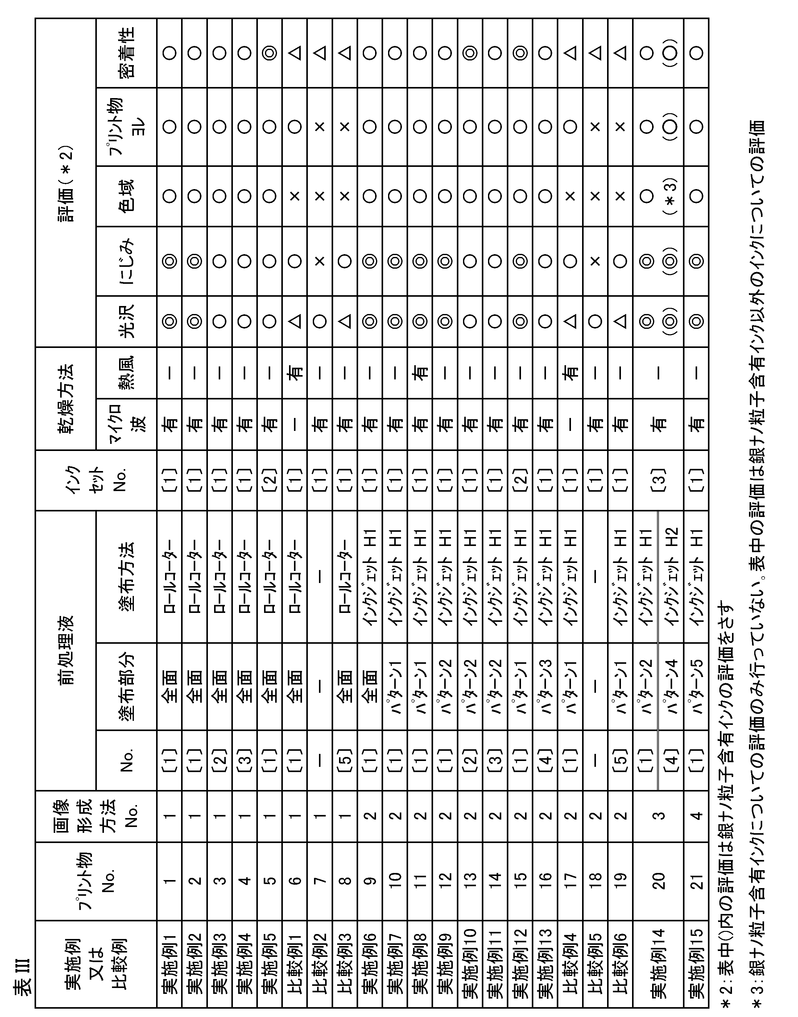
上記表IIIからわかるように、実施例の評価には、△及び×の評価がなく、実施例の方が比較例より総合的に優れていることがわかる。
10 処理液塗布部
11 インクジェットヘッド
12 処理液
15 ロールコーター
20 インク塗布部
21 インクジェットヘッド
22 インク
30 マイクロ波乾燥部
33 乾燥部
35 乾燥装置
41 巻取りローラー
F 基材、記録媒体
C 処理液が塗布された領域
R インクが塗布された領域
CR 処理液12及びインク22が塗布された混合領域
M マイクロ波乾燥装置
D 基材の搬送方向
Hw、HY、HM、HC、HK インク塗布用のインクジェットヘッド
Wpart ホワイトインク塗布部分
Ypart イエローインク塗布部分
Mpart マゼンタインク塗布部分
Cpart シアンインク塗布部分
Kpart ブラックインク塗布部分
H1、H2 処理液塗布用のインクジェットヘッド
H3 金属ナノ粒子含有インク用のインクジェットヘッド
B 発泡層部分
Claims (11)
- 処理液塗布工程と、インク塗布工程と、乾燥工程と、を有する画像形成方法であって、
前記処理液塗布工程にて、基材上に水に溶解してイオン性を有する材料及び溶媒を含有する処理液を塗布し、
前記インク塗布工程にて、顔料、無機粒子又は有機粒子及び溶媒を含有するインクを塗布し、
前記乾燥工程のうち少なくとも一つの乾燥工程にて、マイクロ波を照射することにより塗膜を乾燥させる
ことを特徴とする画像形成方法。 - 前記処理液をインクジェット方式で塗布する
ことを特徴とする請求項1に記載の画像形成方法。 - 前記インクが、電気伝導度の異なる二種以上のインクを用いる
ことを特徴とする請求項1又は請求項2に記載の画像形成方法。 - 前記処理液が、金属塩、カチオン性樹脂又は有機酸を含有する
ことを特徴とする請求項1から請求項3までのいずれか一項に記載の画像形成方法。 - 前記処理液の電気伝導度が、前記インクの電気伝導度以上である
ことを特徴とする請求項1から請求項4までのいずれか一項に記載の画像形成方法。 - 前記処理液が、沸点180℃以上の水溶性溶媒を含有する
ことを特徴とする請求項1から請求項5までのいずれか一項に記載の画像形成方法。 - 前記処理液又は前記インクが、イオン性を有する樹脂を含有する
ことを特徴とする請求項1から請求項6までのいずれか一項に記載の画像形成方法。 - 前記処理液と前記インクの混合塗膜の電気伝導度が50~600mS/mの範囲内である
ことを特徴とする請求項1から請求項7までのいずれか一項に記載の画像形成方法。 - 前記乾燥工程において、前記処理液と前記インクの混合塗膜に熱風を当てる
ことを特徴とする請求項1から請求項8までのいずれか一項に記載の画像形成方法。 - 前記基材が、熱により変形する部位を有する
ことを特徴とする請求項1から請求項9までのいずれか一項に記載の画像形成方法。 - 処理液塗布工程と、インク塗布工程と、乾燥工程と、を有する画像形成装置であって、
請求項1から請求項10までのいずれか一項に記載の画像形成方法を実施する手段を有する
ことを特徴とする画像形成装置。
Priority Applications (2)
| Application Number | Priority Date | Filing Date | Title |
|---|---|---|---|
| JP2024508121A JPWO2023176719A1 (ja) | 2022-03-18 | 2023-03-10 | |
| EP23770674.2A EP4494886A4 (en) | 2022-03-18 | 2023-03-10 | IMAGE FORMING METHOD AND IMAGE FORMING DEVICE |
Applications Claiming Priority (2)
| Application Number | Priority Date | Filing Date | Title |
|---|---|---|---|
| JP2022043313 | 2022-03-18 | ||
| JP2022-043313 | 2022-03-18 |
Publications (1)
| Publication Number | Publication Date |
|---|---|
| WO2023176719A1 true WO2023176719A1 (ja) | 2023-09-21 |
Family
ID=88023734
Family Applications (1)
| Application Number | Title | Priority Date | Filing Date |
|---|---|---|---|
| PCT/JP2023/009290 Ceased WO2023176719A1 (ja) | 2022-03-18 | 2023-03-10 | 画像形成方法及び画像形成装置 |
Country Status (3)
| Country | Link |
|---|---|
| EP (1) | EP4494886A4 (ja) |
| JP (1) | JPWO2023176719A1 (ja) |
| WO (1) | WO2023176719A1 (ja) |
Citations (23)
| Publication number | Priority date | Publication date | Assignee | Title |
|---|---|---|---|---|
| JPS5774192A (en) | 1980-10-28 | 1982-05-10 | Fuji Photo Film Co Ltd | Ink jet recording picture forming method |
| JPS5774193A (en) | 1980-10-28 | 1982-05-10 | Fuji Photo Film Co Ltd | Ink jet recording picture forming method |
| JPS5787988A (en) | 1980-11-21 | 1982-06-01 | Matsushita Electric Ind Co Ltd | Ink jet recording paper |
| JPS5787989A (en) | 1980-11-21 | 1982-06-01 | Matsushita Electric Ind Co Ltd | Ink jet recording paper |
| JPS5942993A (ja) | 1982-09-03 | 1984-03-09 | Canon Inc | インクジエツト記録方法 |
| JPS5952689A (ja) | 1982-09-17 | 1984-03-27 | Mitsubishi Paper Mills Ltd | インクジェット記録用シート |
| JPS6072785A (ja) | 1983-09-30 | 1985-04-24 | Nippon Shokubai Kagaku Kogyo Co Ltd | インクジェット記録用紙 |
| JPS61146591A (ja) | 1984-12-20 | 1986-07-04 | Mitsubishi Paper Mills Ltd | インクジェット記録用紙 |
| JPS61242871A (ja) | 1985-04-22 | 1986-10-29 | Canon Inc | 被記録材 |
| JPS62261476A (ja) | 1986-05-08 | 1987-11-13 | Canon Inc | 被記録材およびそれを用いた記録方法 |
| JPS62280069A (ja) | 1986-05-30 | 1987-12-04 | Canon Inc | 被記録材 |
| JPH0195091A (ja) | 1987-10-08 | 1989-04-13 | Asahi Glass Co Ltd | インクジェット用記録媒体の製造方法 |
| JPH0313376A (ja) | 1989-06-09 | 1991-01-22 | Canon Inc | 被記録材及びこれを用いたインクジェット記録方法 |
| JPH04219266A (ja) | 1990-11-30 | 1992-08-10 | Oji Paper Co Ltd | インクジェット記録用紙 |
| JPH05278259A (ja) | 1992-02-03 | 1993-10-26 | Xerox Corp | マイクロ波乾燥を伴う印刷法 |
| JP2008126413A (ja) * | 2006-11-16 | 2008-06-05 | Fuji Xerox Co Ltd | 画像記録装置および画像記録方法 |
| JP2008183718A (ja) * | 2007-01-26 | 2008-08-14 | Fuji Xerox Co Ltd | 超高速インク吐出装置 |
| JP2010084289A (ja) | 2008-10-01 | 2010-04-15 | Mimaki Engineering Co Ltd | インクジェット捺染方法 |
| JP2010255133A (ja) * | 2009-04-23 | 2010-11-11 | Konica Minolta Ij Technologies Inc | インクジェット捺染方法 |
| JP2015074161A (ja) | 2013-10-09 | 2015-04-20 | セイコーエプソン株式会社 | 印刷装置、印刷方法 |
| JP2017177578A (ja) | 2016-03-30 | 2017-10-05 | ローランドディー.ジー.株式会社 | プリンタおよび印刷用治具 |
| JP2019151071A (ja) | 2018-03-06 | 2019-09-12 | 株式会社リコー | 画像形成装置、画像形成方法、インク、及び記録物の製造方法 |
| JP2020019270A (ja) * | 2017-12-06 | 2020-02-06 | 株式会社リコー | 画像形成方法、画像形成装置、及び印刷物の製造方法 |
Family Cites Families (2)
| Publication number | Priority date | Publication date | Assignee | Title |
|---|---|---|---|---|
| EP2614964B1 (en) * | 2012-01-10 | 2017-01-04 | Ricoh Company, Ltd. | Image forming method |
| EP3495154B1 (en) * | 2017-12-06 | 2025-07-30 | Ricoh Company, Ltd. | Image forming method, image forming device, and method of manufacturing printed matter |
-
2023
- 2023-03-10 EP EP23770674.2A patent/EP4494886A4/en active Pending
- 2023-03-10 WO PCT/JP2023/009290 patent/WO2023176719A1/ja not_active Ceased
- 2023-03-10 JP JP2024508121A patent/JPWO2023176719A1/ja active Pending
Patent Citations (23)
| Publication number | Priority date | Publication date | Assignee | Title |
|---|---|---|---|---|
| JPS5774192A (en) | 1980-10-28 | 1982-05-10 | Fuji Photo Film Co Ltd | Ink jet recording picture forming method |
| JPS5774193A (en) | 1980-10-28 | 1982-05-10 | Fuji Photo Film Co Ltd | Ink jet recording picture forming method |
| JPS5787988A (en) | 1980-11-21 | 1982-06-01 | Matsushita Electric Ind Co Ltd | Ink jet recording paper |
| JPS5787989A (en) | 1980-11-21 | 1982-06-01 | Matsushita Electric Ind Co Ltd | Ink jet recording paper |
| JPS5942993A (ja) | 1982-09-03 | 1984-03-09 | Canon Inc | インクジエツト記録方法 |
| JPS5952689A (ja) | 1982-09-17 | 1984-03-27 | Mitsubishi Paper Mills Ltd | インクジェット記録用シート |
| JPS6072785A (ja) | 1983-09-30 | 1985-04-24 | Nippon Shokubai Kagaku Kogyo Co Ltd | インクジェット記録用紙 |
| JPS61146591A (ja) | 1984-12-20 | 1986-07-04 | Mitsubishi Paper Mills Ltd | インクジェット記録用紙 |
| JPS61242871A (ja) | 1985-04-22 | 1986-10-29 | Canon Inc | 被記録材 |
| JPS62261476A (ja) | 1986-05-08 | 1987-11-13 | Canon Inc | 被記録材およびそれを用いた記録方法 |
| JPS62280069A (ja) | 1986-05-30 | 1987-12-04 | Canon Inc | 被記録材 |
| JPH0195091A (ja) | 1987-10-08 | 1989-04-13 | Asahi Glass Co Ltd | インクジェット用記録媒体の製造方法 |
| JPH0313376A (ja) | 1989-06-09 | 1991-01-22 | Canon Inc | 被記録材及びこれを用いたインクジェット記録方法 |
| JPH04219266A (ja) | 1990-11-30 | 1992-08-10 | Oji Paper Co Ltd | インクジェット記録用紙 |
| JPH05278259A (ja) | 1992-02-03 | 1993-10-26 | Xerox Corp | マイクロ波乾燥を伴う印刷法 |
| JP2008126413A (ja) * | 2006-11-16 | 2008-06-05 | Fuji Xerox Co Ltd | 画像記録装置および画像記録方法 |
| JP2008183718A (ja) * | 2007-01-26 | 2008-08-14 | Fuji Xerox Co Ltd | 超高速インク吐出装置 |
| JP2010084289A (ja) | 2008-10-01 | 2010-04-15 | Mimaki Engineering Co Ltd | インクジェット捺染方法 |
| JP2010255133A (ja) * | 2009-04-23 | 2010-11-11 | Konica Minolta Ij Technologies Inc | インクジェット捺染方法 |
| JP2015074161A (ja) | 2013-10-09 | 2015-04-20 | セイコーエプソン株式会社 | 印刷装置、印刷方法 |
| JP2017177578A (ja) | 2016-03-30 | 2017-10-05 | ローランドディー.ジー.株式会社 | プリンタおよび印刷用治具 |
| JP2020019270A (ja) * | 2017-12-06 | 2020-02-06 | 株式会社リコー | 画像形成方法、画像形成装置、及び印刷物の製造方法 |
| JP2019151071A (ja) | 2018-03-06 | 2019-09-12 | 株式会社リコー | 画像形成装置、画像形成方法、インク、及び記録物の製造方法 |
Non-Patent Citations (1)
| Title |
|---|
| See also references of EP4494886A4 |
Also Published As
| Publication number | Publication date |
|---|---|
| EP4494886A4 (en) | 2025-05-07 |
| EP4494886A1 (en) | 2025-01-22 |
| JPWO2023176719A1 (ja) | 2023-09-21 |
Similar Documents
| Publication | Publication Date | Title |
|---|---|---|
| JP7582213B2 (ja) | インクジェット記録方法及び画像記録物 | |
| JP7110755B2 (ja) | インクジェット記録液セット、インクジェット記録用前処理液の製造方法、印刷物及びインクジェット記録方法 | |
| JP7331565B2 (ja) | インクジェット記録液セット、印刷物及びインクジェット記録方法 | |
| JP7091776B2 (ja) | インクジェット記録用前処理液、インクジェット記録液セット、インクジェット記録用前処理液の製造方法、印刷物及びインクジェット記録方法 | |
| WO2017009601A1 (en) | Method for printing on water-soluble material | |
| JP7251308B2 (ja) | インクジェット記録液セット、画像形成方法および印刷物 | |
| JP7516927B2 (ja) | インクジェット記録液セットおよび当該インクジェット記録液セットを用いる画像形成方法 | |
| JP2025072506A (ja) | インクセット | |
| WO2024188738A1 (en) | Liquid set for inkjet printing comprising an aqueous pre-treatment liquid, an aqueous inkjet ink and a varnish | |
| JP7528575B2 (ja) | 前処理液、当該前処理液を含むインクジェット記録液セットおよび画像形成方法 | |
| JP7214984B2 (ja) | インクジェット記録液セット及びインクジェット記録方法 | |
| JP7192376B2 (ja) | インクジェット記録液セット、インクジェット記録用前処理液の製造方法、印刷物及びインクジェット記録方法 | |
| JP7180262B2 (ja) | インクジェット記録用前処理液、インクジェット記録用前処理液の製造方法、インクジェット記録液セット、印刷物及びインクジェット記録方法 | |
| WO2023176719A1 (ja) | 画像形成方法及び画像形成装置 | |
| JP7735847B2 (ja) | 画像形成方法 | |
| WO2022158339A1 (ja) | インクジェット記録方法 | |
| JP2024157644A (ja) | 画像形成方法及び画像形成システム | |
| WO2024225212A1 (ja) | 画像形成方法及び画像形成システム | |
| JP7810251B2 (ja) | インクジェット記録用インク、インクジェット記録用インクの製造方法、インクジェット記録用インクセット、画像形成方法及び画像形成装置 | |
| EP4685198A1 (en) | Ink set, inkjet recording method, and inkjet recording system | |
| JP7708177B2 (ja) | インクセット及びインクジェット記録方法 | |
| WO2025154438A1 (ja) | インクセット、インクジェット記録方法及び記録装置 | |
| JP2021042263A (ja) | 水性インクジェットインク、印刷物及びインクジェット記録方法 | |
| WO2023105737A1 (ja) | インクジェット記録用インクセット、インクジェット記録方法及びインクジェット記録装置 | |
| JP2024080207A (ja) | 水性インクセット、水性インクセットの製造方法、インクジェット記録方法及びインクジェット記録システム |
Legal Events
| Date | Code | Title | Description |
|---|---|---|---|
| 121 | Ep: the epo has been informed by wipo that ep was designated in this application |
Ref document number: 23770674 Country of ref document: EP Kind code of ref document: A1 |
|
| ENP | Entry into the national phase |
Ref document number: 2024508121 Country of ref document: JP Kind code of ref document: A |
|
| WWE | Wipo information: entry into national phase |
Ref document number: 2023770674 Country of ref document: EP |
|
| NENP | Non-entry into the national phase |
Ref country code: DE |
|
| ENP | Entry into the national phase |
Ref document number: 2023770674 Country of ref document: EP Effective date: 20241018 |