WO2023176722A1 - 蓄電装置 - Google Patents
蓄電装置 Download PDFInfo
- Publication number
- WO2023176722A1 WO2023176722A1 PCT/JP2023/009316 JP2023009316W WO2023176722A1 WO 2023176722 A1 WO2023176722 A1 WO 2023176722A1 JP 2023009316 W JP2023009316 W JP 2023009316W WO 2023176722 A1 WO2023176722 A1 WO 2023176722A1
- Authority
- WO
- WIPO (PCT)
- Prior art keywords
- power storage
- protrusion
- holder
- storage element
- lid
- Prior art date
- Legal status (The legal status is an assumption and is not a legal conclusion. Google has not performed a legal analysis and makes no representation as to the accuracy of the status listed.)
- Ceased
Links
Images





Classifications
-
- H—ELECTRICITY
- H01—ELECTRIC ELEMENTS
- H01G—CAPACITORS; CAPACITORS, RECTIFIERS, DETECTORS, SWITCHING DEVICES, LIGHT-SENSITIVE OR TEMPERATURE-SENSITIVE DEVICES OF THE ELECTROLYTIC TYPE
- H01G11/00—Hybrid capacitors, i.e. capacitors having different positive and negative electrodes; Electric double-layer [EDL] capacitors; Processes for the manufacture thereof or of parts thereof
- H01G11/10—Multiple hybrid or EDL capacitors, e.g. arrays or modules
-
- H—ELECTRICITY
- H01—ELECTRIC ELEMENTS
- H01G—CAPACITORS; CAPACITORS, RECTIFIERS, DETECTORS, SWITCHING DEVICES, LIGHT-SENSITIVE OR TEMPERATURE-SENSITIVE DEVICES OF THE ELECTROLYTIC TYPE
- H01G11/00—Hybrid capacitors, i.e. capacitors having different positive and negative electrodes; Electric double-layer [EDL] capacitors; Processes for the manufacture thereof or of parts thereof
- H01G11/74—Terminals, e.g. extensions of current collectors
- H01G11/76—Terminals, e.g. extensions of current collectors specially adapted for integration in multiple or stacked hybrid or EDL capacitors
-
- H—ELECTRICITY
- H01—ELECTRIC ELEMENTS
- H01G—CAPACITORS; CAPACITORS, RECTIFIERS, DETECTORS, SWITCHING DEVICES, LIGHT-SENSITIVE OR TEMPERATURE-SENSITIVE DEVICES OF THE ELECTROLYTIC TYPE
- H01G11/00—Hybrid capacitors, i.e. capacitors having different positive and negative electrodes; Electric double-layer [EDL] capacitors; Processes for the manufacture thereof or of parts thereof
- H01G11/78—Cases; Housings; Encapsulations; Mountings
- H01G11/82—Fixing or assembling a capacitive element in a housing, e.g. mounting electrodes, current collectors or terminals in containers or encapsulations
-
- H—ELECTRICITY
- H01—ELECTRIC ELEMENTS
- H01M—PROCESSES OR MEANS, e.g. BATTERIES, FOR THE DIRECT CONVERSION OF CHEMICAL ENERGY INTO ELECTRICAL ENERGY
- H01M50/00—Constructional details or processes of manufacture of the non-active parts of electrochemical cells other than fuel cells, e.g. hybrid cells
- H01M50/20—Mountings; Secondary casings or frames; Racks, modules or packs; Suspension devices; Shock absorbers; Transport or carrying devices; Holders
- H01M50/204—Racks, modules or packs for multiple batteries or multiple cells
- H01M50/207—Racks, modules or packs for multiple batteries or multiple cells characterised by their shape
- H01M50/209—Racks, modules or packs for multiple batteries or multiple cells characterised by their shape adapted for prismatic or rectangular cells
-
- H—ELECTRICITY
- H01—ELECTRIC ELEMENTS
- H01M—PROCESSES OR MEANS, e.g. BATTERIES, FOR THE DIRECT CONVERSION OF CHEMICAL ENERGY INTO ELECTRICAL ENERGY
- H01M50/00—Constructional details or processes of manufacture of the non-active parts of electrochemical cells other than fuel cells, e.g. hybrid cells
- H01M50/20—Mountings; Secondary casings or frames; Racks, modules or packs; Suspension devices; Shock absorbers; Transport or carrying devices; Holders
- H01M50/233—Mountings; Secondary casings or frames; Racks, modules or packs; Suspension devices; Shock absorbers; Transport or carrying devices; Holders characterised by physical properties of casings or racks, e.g. dimensions
- H01M50/242—Mountings; Secondary casings or frames; Racks, modules or packs; Suspension devices; Shock absorbers; Transport or carrying devices; Holders characterised by physical properties of casings or racks, e.g. dimensions adapted for protecting batteries against vibrations, collision impact or swelling
-
- H—ELECTRICITY
- H01—ELECTRIC ELEMENTS
- H01M—PROCESSES OR MEANS, e.g. BATTERIES, FOR THE DIRECT CONVERSION OF CHEMICAL ENERGY INTO ELECTRICAL ENERGY
- H01M50/00—Constructional details or processes of manufacture of the non-active parts of electrochemical cells other than fuel cells, e.g. hybrid cells
- H01M50/20—Mountings; Secondary casings or frames; Racks, modules or packs; Suspension devices; Shock absorbers; Transport or carrying devices; Holders
- H01M50/262—Mountings; Secondary casings or frames; Racks, modules or packs; Suspension devices; Shock absorbers; Transport or carrying devices; Holders with fastening means, e.g. locks
- H01M50/264—Mountings; Secondary casings or frames; Racks, modules or packs; Suspension devices; Shock absorbers; Transport or carrying devices; Holders with fastening means, e.g. locks for cells or batteries, e.g. straps, tie rods or peripheral frames
-
- H—ELECTRICITY
- H01—ELECTRIC ELEMENTS
- H01M—PROCESSES OR MEANS, e.g. BATTERIES, FOR THE DIRECT CONVERSION OF CHEMICAL ENERGY INTO ELECTRICAL ENERGY
- H01M50/00—Constructional details or processes of manufacture of the non-active parts of electrochemical cells other than fuel cells, e.g. hybrid cells
- H01M50/20—Mountings; Secondary casings or frames; Racks, modules or packs; Suspension devices; Shock absorbers; Transport or carrying devices; Holders
- H01M50/271—Lids or covers for the racks or secondary casings
-
- H—ELECTRICITY
- H01—ELECTRIC ELEMENTS
- H01M—PROCESSES OR MEANS, e.g. BATTERIES, FOR THE DIRECT CONVERSION OF CHEMICAL ENERGY INTO ELECTRICAL ENERGY
- H01M50/00—Constructional details or processes of manufacture of the non-active parts of electrochemical cells other than fuel cells, e.g. hybrid cells
- H01M50/20—Mountings; Secondary casings or frames; Racks, modules or packs; Suspension devices; Shock absorbers; Transport or carrying devices; Holders
- H01M50/289—Mountings; Secondary casings or frames; Racks, modules or packs; Suspension devices; Shock absorbers; Transport or carrying devices; Holders characterised by spacing elements or positioning means within frames, racks or packs
-
- H—ELECTRICITY
- H01—ELECTRIC ELEMENTS
- H01M—PROCESSES OR MEANS, e.g. BATTERIES, FOR THE DIRECT CONVERSION OF CHEMICAL ENERGY INTO ELECTRICAL ENERGY
- H01M50/00—Constructional details or processes of manufacture of the non-active parts of electrochemical cells other than fuel cells, e.g. hybrid cells
- H01M50/50—Current conducting connections for cells or batteries
- H01M50/502—Interconnectors for connecting terminals of adjacent batteries; Interconnectors for connecting cells outside a battery casing
- H01M50/507—Interconnectors for connecting terminals of adjacent batteries; Interconnectors for connecting cells outside a battery casing comprising an arrangement of two or more busbars within a container structure, e.g. busbar modules
-
- H—ELECTRICITY
- H01—ELECTRIC ELEMENTS
- H01M—PROCESSES OR MEANS, e.g. BATTERIES, FOR THE DIRECT CONVERSION OF CHEMICAL ENERGY INTO ELECTRICAL ENERGY
- H01M50/00—Constructional details or processes of manufacture of the non-active parts of electrochemical cells other than fuel cells, e.g. hybrid cells
- H01M50/50—Current conducting connections for cells or batteries
- H01M50/572—Means for preventing undesired use or discharge
- H01M50/584—Means for preventing undesired use or discharge for preventing incorrect connections inside or outside the batteries
- H01M50/588—Means for preventing undesired use or discharge for preventing incorrect connections inside or outside the batteries outside the batteries, e.g. incorrect connections of terminals or busbars
-
- H—ELECTRICITY
- H01—ELECTRIC ELEMENTS
- H01M—PROCESSES OR MEANS, e.g. BATTERIES, FOR THE DIRECT CONVERSION OF CHEMICAL ENERGY INTO ELECTRICAL ENERGY
- H01M50/00—Constructional details or processes of manufacture of the non-active parts of electrochemical cells other than fuel cells, e.g. hybrid cells
- H01M50/50—Current conducting connections for cells or batteries
- H01M50/572—Means for preventing undesired use or discharge
- H01M50/584—Means for preventing undesired use or discharge for preventing incorrect connections inside or outside the batteries
- H01M50/59—Means for preventing undesired use or discharge for preventing incorrect connections inside or outside the batteries characterised by the protection means
- H01M50/591—Covers
-
- H—ELECTRICITY
- H01—ELECTRIC ELEMENTS
- H01G—CAPACITORS; CAPACITORS, RECTIFIERS, DETECTORS, SWITCHING DEVICES, LIGHT-SENSITIVE OR TEMPERATURE-SENSITIVE DEVICES OF THE ELECTROLYTIC TYPE
- H01G11/00—Hybrid capacitors, i.e. capacitors having different positive and negative electrodes; Electric double-layer [EDL] capacitors; Processes for the manufacture thereof or of parts thereof
- H01G11/10—Multiple hybrid or EDL capacitors, e.g. arrays or modules
- H01G11/12—Stacked hybrid or EDL capacitors
-
- H—ELECTRICITY
- H01—ELECTRIC ELEMENTS
- H01G—CAPACITORS; CAPACITORS, RECTIFIERS, DETECTORS, SWITCHING DEVICES, LIGHT-SENSITIVE OR TEMPERATURE-SENSITIVE DEVICES OF THE ELECTROLYTIC TYPE
- H01G9/00—Electrolytic capacitors, rectifiers, detectors, switching devices, light-sensitive or temperature-sensitive devices; Processes of their manufacture
- H01G9/004—Details
- H01G9/08—Housing; Encapsulation
-
- H—ELECTRICITY
- H01—ELECTRIC ELEMENTS
- H01M—PROCESSES OR MEANS, e.g. BATTERIES, FOR THE DIRECT CONVERSION OF CHEMICAL ENERGY INTO ELECTRICAL ENERGY
- H01M2220/00—Batteries for particular applications
- H01M2220/20—Batteries in motive systems, e.g. vehicle, ship, plane
-
- Y—GENERAL TAGGING OF NEW TECHNOLOGICAL DEVELOPMENTS; GENERAL TAGGING OF CROSS-SECTIONAL TECHNOLOGIES SPANNING OVER SEVERAL SECTIONS OF THE IPC; TECHNICAL SUBJECTS COVERED BY FORMER USPC CROSS-REFERENCE ART COLLECTIONS [XRACs] AND DIGESTS
- Y02—TECHNOLOGIES OR APPLICATIONS FOR MITIGATION OR ADAPTATION AGAINST CLIMATE CHANGE
- Y02E—REDUCTION OF GREENHOUSE GAS [GHG] EMISSIONS, RELATED TO ENERGY GENERATION, TRANSMISSION OR DISTRIBUTION
- Y02E60/00—Enabling technologies; Technologies with a potential or indirect contribution to GHG emissions mitigation
- Y02E60/10—Energy storage using batteries
Definitions
- the present invention relates to a power storage device.
- Patent Document 1 discloses a secondary battery pack that includes an exterior case having an openable and closable lid and a plurality of single cells housed in the exterior case.
- a fixture that protrudes into the interior of the exterior case is attached to the lid with bolts or the like. This fixture can fix the unit cell to the outer case by pressing the outer surface of the unit cell.
- a power storage device that includes a power storage element and an exterior body that houses the power storage element
- problems may occur at the joint between the power storage element and the conductive member, etc.
- An event may occur that impairs the reliability of the power storage device.
- the single cell in the outer case is held down by a fixture from above, thereby suppressing vertical movement of the single cell.
- it is necessary to attach a fixture, which is a separate member, inside the outer case, which increases the number of parts of the secondary battery pack or complicates the manufacturing process.
- the present invention was achieved by the inventors of the present invention paying new attention to the above-mentioned problem, and aims to provide a power storage device with a simple configuration and improved reliability.
- a power storage device includes a plurality of power storage elements arranged side by side, a plurality of holders, and an exterior body that accommodates the plurality of power storage elements and the plurality of holders, are arranged along a side surface of one of the plurality of power storage elements in the direction in which the plurality of power storage elements are lined up, and the exterior body includes an exterior body main body having an opening; and a lid that closes the opening, the lid being a protrusion that protrudes toward at least one of the plurality of holders, the at least one holder being directed toward the at least one holder. It has a protrusion that presses in the direction.
- a power storage device includes a power storage element, a holder that holds the power storage element, and an exterior body that houses the power storage element and the holder, and the exterior body has an opening. It has a main body and a lid that closes the opening, and the lid has a protrusion that protrudes toward the holder and that presses the holder in the direction of protrusion of the protrusion.
- the protruding portion presses a region of the holder that does not overlap with the power storage element when viewed from the direction in which the lid and the exterior body are lined up.
- a power storage device includes a plurality of power storage elements arranged side by side, a plurality of holders, and an exterior body that accommodates the plurality of power storage elements and the plurality of holders, are arranged along a side surface of one of the plurality of power storage elements in the direction in which the plurality of power storage elements are lined up, and the exterior body includes an exterior body main body having an opening; a lid body that closes the opening, the lid body having a protrusion that protrudes toward at least one of the plurality of holders, and a protrusion of the protrusion that protrudes toward the at least one holder. It has a protrusion that makes contact in the direction.
- a power storage device includes a power storage element, a holder that holds the power storage element, and an exterior body that houses the power storage element and the holder, and the exterior body has an opening. It has a main body and a lid that closes the opening, and the lid has a protrusion that protrudes toward the holder and that contacts the holder in the direction in which the protrusion protrudes. , the protrusion comes into contact with a region of the holder that does not overlap with the electricity storage element when viewed from the direction in which the lid and the exterior body are lined up.
- a power storage device with a simple configuration and improved reliability can be provided.
- FIG. 1 is a perspective view showing the appearance of a power storage device according to an embodiment.
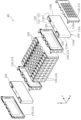
- FIG. 2 is an exploded perspective view of the power storage device according to the embodiment.
- FIG. 3 is an exploded perspective view of the power storage element unit according to the embodiment.
- FIG. 4 is a perspective sectional view of the power storage device according to the embodiment.
- FIG. 5 is a perspective view showing the appearance of the cell holder according to the embodiment.
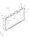
- FIG. 6 is a perspective view of the lid according to the embodiment.
- FIG. 7 is a perspective view showing the structural relationship between a protrusion, a plurality of cell holders, and a plurality of power storage elements according to the embodiment.
- FIG. 8 is a plan view of the cell holder according to the embodiment, showing a position where the cell holder contacts or is pressed by a protrusion.
- FIG. 9 is a cross-sectional view schematically showing the configuration of a protrusion and its surroundings according to Modification 1 of the embodiment.
- FIG. 10 is a cross-sectional view schematically showing the configuration of a protrusion and its surroundings according to a second modification of the embodiment.
- FIG. 11 is a cross-sectional view schematically showing the configuration of a protrusion and its surroundings according to Modification 3 of the embodiment.
- a power storage device includes a plurality of power storage elements arranged side by side, a plurality of holders, and an exterior body that houses the plurality of power storage elements and the plurality of holders, and the power storage device includes: Each of the plurality of holders is arranged along a side surface of one of the plurality of power storage elements in the direction in which the plurality of power storage elements are arranged, and the outer case has an opening.
- the lid includes a main body and a lid that closes the opening, and the lid is a protrusion that protrudes toward at least one of the plurality of holders, and the lid is a protrusion that protrudes toward at least one of the plurality of holders. It has a protrusion that presses in the direction in which the part protrudes.
- the holder that holds the power storage element is held down by the protrusion of the lid.
- movement of the holder can be restricted inside the exterior body, and as a result, movement of the electricity storage element held by the holder is restricted. Therefore, in a power storage device including a plurality of power storage elements, movement (positional shift) of the plurality of power storage elements due to vibration or impact during manufacturing, use, transportation, etc. of the power storage device is suppressed. This suppresses the occurrence of malfunctions in the power storage device due to vibration or impact.
- the protrusion restricts the movement of the power storage element via the holder, the power storage element is less likely to be damaged by the protrusion. In this manner, the power storage device according to the present aspect has a simple configuration and improved reliability.
- the power storage device further includes an insulating member disposed between the power storage element and the lid, and the protruding portion is connected to the power storage device through the insulating member.
- the at least one holder may be pressed in the protruding direction by pressing the at least one holder.
- the power storage device described in (2) above even if the holder is made of a relatively hard material to improve the reliability of holding the power storage element, there is a gap between the protrusion and the holder.
- the intervening insulating member allows tolerances of the protrusion and the holder to be accommodated. Therefore, damage to the power storage element due to the pressing force of the protrusion is more reliably suppressed.
- the power storage element has a terminal
- the insulating member is a busbar holder that holds a busbar joined to the terminal, or a busbar and the lid body.
- a busbar cover may be disposed between the busbars and cover the busbars.
- the busbar holder or busbar cover used for positioning the busbar or electrically insulating the busbar from other members is Can be used as a component.
- grooves or convex portions with which the protrusion comes into contact are provided at positions facing each other in the protrusion direction. good.
- the tip of the protrusion is guided inward of the groove. can be held down.
- the protrusion can press the holder more reliably, directly or indirectly. If a protrusion is provided at a position facing the protrusion, at least a portion of the protrusion is actively pushed by the protrusion, or is crushed as a result, so that the protrusion directly pushes against the holder. can be held down more reliably either directly or indirectly.
- the protrusion portion is arranged so that the at least one holder is not attached to the at least one holder when viewed from the direction in which the lid body and the exterior body main body are lined up. In this case, an area that does not overlap with the electricity storage element may be held down.
- the pressing force by the protrusion is difficult to be applied to the power storage element. Therefore, there is a low possibility that damage to the power storage element will occur, and furthermore, even if the movement of the holder and the power storage element is more reliably restricted by increasing the pressing force of the protrusion against the holder, the pressing force may be increased. Deformation of the storage element container due to pressure is unlikely to occur.
- the protruding portion may collectively press the plurality of holders in the protruding direction.
- one protrusion can hold the plurality of holders to approximately uniform positions in the protrusion direction of the protrusion, so that gaps between the positions of the plurality of power storage elements are reduced. Hard to occur. Therefore, stress concentration due to displacement of the two or more power storage elements in the protruding direction of the protruding portions is unlikely to occur at the joint portion of the bus bar that is joined to two or more adjacent power storage elements.
- a power storage device includes a power storage element, a holder that holds the power storage element, and an exterior body that houses the power storage element and the holder, and the exterior body has an opening. and a lid body that closes the opening, the lid body having a protrusion that protrudes toward the holder and that presses the holder in a protruding direction of the protrusion.
- the protruding portion presses an area of the holder that does not overlap with the electricity storage element when viewed from the direction in which the lid and the exterior body are lined up.
- the holder that holds the power storage element is held down by the protrusion of the lid.
- movement of the holder within the exterior body can be restricted, and as a result, movement of the electricity storage element held by the holder is restricted.
- Movement of the power storage element inside the exterior body is restricted by the lid body.
- the protrusion presses down on the holder at a position that does not overlap with the power storage element it is difficult for the protrusion to apply a pressing force to the power storage element.
- the power storage device is a power storage device with a simple configuration and improved reliability.
- a power storage device includes a plurality of power storage elements arranged side by side, a plurality of holders, and an exterior body that accommodates the plurality of power storage elements and the plurality of holders, and the power storage device includes: Each of the plurality of holders is arranged along a side surface of one of the plurality of power storage elements in the direction in which the plurality of power storage elements are arranged, and the outer case has an opening.
- the lid includes a main body and a lid that closes the opening, and the lid is a protrusion that protrudes toward at least one of the plurality of holders, and the lid has a protrusion that protrudes toward at least one of the plurality of holders. It has a protruding part that contacts in the protruding direction of the part.
- the power storage device by fixing the lid to the exterior body, the holder that holds the power storage element comes into contact with the protrusion of the lid. Thereby, movement of the holder within the exterior body can be restricted, and as a result, movement of the electricity storage element held by the holder is restricted. Therefore, in a power storage device including a plurality of power storage elements, movement (positional shift) of the plurality of power storage elements due to vibration or impact during manufacturing, use, transportation, etc. of the power storage device is suppressed. This suppresses the occurrence of malfunctions in the power storage device due to vibration or impact. Furthermore, since the protrusion restricts the movement of the power storage element via the holder, the power storage element is less likely to be damaged by the protrusion. In this manner, the power storage device according to the present aspect has a simple configuration and improved reliability.
- a power storage device includes a power storage element, a holder that holds the power storage element, and an exterior body that houses the power storage element and the holder, and the exterior body has an opening. and a lid body that closes the opening, the lid body being a protrusion that protrudes toward the holder, and that contacts the holder in the protrusion direction of the protrusion.
- the protruding portion contacts an area of the holder that does not overlap with the electricity storage element when viewed from the direction in which the lid and the exterior body are lined up.
- the power storage device by fixing the lid to the exterior body, the holder that holds the power storage element comes into contact with the protrusion of the lid. Thereby, movement of the holder within the exterior body can be restricted, and as a result, movement of the electricity storage element held by the holder is restricted. Movement of the power storage element inside the exterior body (particularly movement in the direction in which the lid body and the exterior body body are lined up) is restricted by the lid body. Furthermore, since the protrusion comes into contact with the holder at a position that does not overlap with the power storage element, the power storage element is less likely to be affected by the protrusion. Therefore, the container of the power storage element is unlikely to be deformed due to contact between the protrusions. In this way, the power storage device according to this aspect is a power storage device with a simple configuration and improved reliability.
- the direction in which the short sides of the power storage element face each other or the longitudinal direction of the lid plate of the container of the power storage element is defined as the Y-axis direction.
- the direction in which the plurality of power storage elements are lined up or the direction in which the long sides of the power storage elements face each other is defined as the X-axis direction.
- the direction in which the main body of the exterior body (the body of the exterior body) of the power storage device and the lid body are lined up, or the vertical direction is defined as the Z-axis direction.
- These X-axis direction, Y-axis direction, and Z-axis direction are directions that intersect with each other (orthogonal in this embodiment).
- the Z-axis direction may not be the vertical direction, but for convenience of explanation, the Z-axis direction will be described as the vertical direction below.
- the X-axis plus direction indicates the arrow direction of the X-axis
- the X-axis minus direction indicates the opposite direction to the X-axis plus direction.
- X-axis direction it means both directions or either direction parallel to the X-axis.
- FIG. 1 is a perspective view showing the appearance of a power storage device 1 according to an embodiment.
- FIG. 2 is an exploded perspective view of power storage device 1 according to the embodiment.
- FIG. 3 is an exploded perspective view of the power storage element unit 20 according to the embodiment.
- Inside the exterior body 10 in addition to the members shown in FIG. 2 and subsequent figures, other members such as temperature and voltage measurement sensors and electric wires connected to the sensors are also housed. Illustrations and explanations of members will be omitted.
- the power storage device 1 is a device that can charge electricity from the outside and discharge electricity to the outside.
- the power storage device 1 is a battery module (battery assembly) used for power storage, power supply, or the like.
- the power storage device 1 is used for driving or starting an engine of a moving object such as an automobile, a motorcycle, a watercraft, a ship, a snowmobile, an agricultural machine, a construction machine, or a railway vehicle for an electric railway. Used as batteries, etc.
- Examples of the above-mentioned vehicles include electric vehicles (EVs), hybrid electric vehicles (HEVs), plug-in hybrid electric vehicles (PHEVs), and fossil fuel (gasoline, diesel oil, liquefied natural gas, etc.) vehicles.
- Examples of the above-mentioned railway vehicles for electric railways include electric trains, monorails, linear motor cars, and hybrid electric trains equipped with both a diesel engine and an electric motor.
- the power storage device 1 can also be used as a stationary battery or the like used for home or business purposes.
- the power storage device 1 includes an exterior body 10 and a power storage element unit 20 housed in the exterior body 10.
- Two types of insulating members 30 are arranged above the power storage element unit 20. Specifically, above the power storage element unit 20, there are a busbar holder 30A that holds the busbar 60 joined to the power storage element 100, and a busbar cover 30B that covers the busbar 60 and is fixed to the busbar holder 30A. It is located.
- the term "insulating member 30" refers to at least one of the bus bar holder 30A and the bus bar cover 30B.
- the exterior body 10 is a box-shaped container (module case) that constitutes the housing of the power storage device 1.
- the exterior body 10 may be any container that forms a space inside, and the outer shape of the exterior body 10 is determined as appropriate.
- the exterior body 10 is disposed outside the power storage element unit 20 and the bus bar holder 30A, fixes these in a predetermined position, and protects them from impact and the like.
- the exterior body 10 is made of metal such as iron, aluminum, and aluminum alloy. As the material for forming the exterior body 10, resin or the like can be used in addition to metal.
- the resins include polycarbonate (PC), polypropylene (PP), polyethylene (PE), polystyrene (PS), polyphenylene sulfide resin (PPS), polyphenylene ether (PPE (including modified PPE)), and polyethylene terephthalate (PET). , polybutylene terephthalate (PBT), polyether ether ketone (PEEK), tetrafluoroethylene perfluoroalkyl vinyl ether (PFA), polytetrafluoroethylene (PTFE), polyether sulfone (PES), polyamide (PA), ABS An example is resin.
- PC polycarbonate
- PP polypropylene
- PE polyethylene
- PS polystyrene
- PPS polyphenylene sulfide resin
- PPE polyphenylene ether
- PET polyethylene terephthalate
- PBT polybutylene terephthalate
- PEEK polyether ether ketone
- PFA tetrafluoro
- the exterior body 10 has an opening 12a provided at an end in the positive Z-axis direction into which the power storage element unit 20 can be inserted, and a bottom wall 19 provided at a position facing the opening 12a.
- the exterior body 10 includes an exterior body body 12 and a lid body 11, and the opening portion 12a and the bottom wall portion 19 are provided in the exterior body body 12.
- the exterior body 12 is a bottomed rectangular cylindrical housing in which an opening 12 a is formed, and accommodates the power storage element unit 20 .
- the exterior body 12 has side walls 15 and 17 that face each other in the Y-axis direction and partition the inside and outside of the exterior body 10 .
- the power storage element unit 20 is arranged between the outer wall portion 17 and the side wall portion 15 in the Y-axis direction.
- the exterior body 10 may include elements not shown in FIGS. 1 and 2, such as an exhaust pipe for exhausting gas inside the exterior body 10 to the outside.
- the lid 11 is a rectangular member that closes the opening 12a of the exterior body 12.
- the lid 11 is joined to the exterior body 12 by a plurality of bolts 41, thereby fixing the lid 11 to the exterior body 12.
- a through hole 43 through which a bolt 41 passes is provided in the peripheral edge of the lid 11, and a fixing hole 42 is provided in the opening peripheral edge 12b, which is the peripheral edge of the opening 12a of the exterior body 12. It is provided.
- the bolt 41 passes through the through hole 43 of the lid 11 and is screwed into the fixing hole 42 of the exterior body 12. Thereby, the lid body 11 is joined to the opening peripheral portion 12b of the exterior body main body 12.
- the lid 11 has a protrusion 18 that protrudes from the inner surface of the lid 11 (surface in the negative Z-axis direction) toward the power storage element unit 20. have.
- the protruding portion 18 is a part of the lid 11 and is a portion that holds down the plurality of cell holders 130 that the power storage element unit 20 has. The structure of the protrusion 18 and its surroundings will be described later using FIGS. 4 to 8.
- the power storage element unit 20 includes a plurality of power storage elements 100 and a cell holder 130 that holds each of the plurality of power storage elements 100.
- the power storage element 100 is a secondary battery (single battery) that can charge and discharge electricity, and more specifically, is a non-aqueous electrolyte secondary battery such as a lithium ion secondary battery.
- the power storage element 100 includes a flat rectangular parallelepiped (prismatic) container 110 and a pair of terminals 120 (positive and negative) fixed to the container 110. Inside the container 110, an electrode body, a current collecting member, an electrolytic solution, etc. (not shown) are housed.
- An example of the electrode body of the power storage element 100 is a wound type electrode body formed by winding a separator arranged in layers such that a separator is sandwiched between a positive electrode plate and a negative electrode plate.
- the power storage element 100 may include a stacked electrode body formed by stacking a plurality of flat plates, or a bellows-type electrode body formed by folding the plates into a bellows shape. .
- the power storage element 100 is not limited to a nonaqueous electrolyte secondary battery, and may be a secondary battery other than a nonaqueous electrolyte secondary battery or a capacitor.
- the power storage element 100 may be not a secondary battery but a primary battery that allows the user to use the stored electricity without charging it.
- Power storage element 100 may be a battery using a solid electrolyte.
- the power storage element 100 may be a pouch type power storage element.
- the shape of the power storage element 100 is not limited to the above-mentioned rectangular shape, and may be a polygonal column shape, a cylindrical shape, an elliptical column shape, an elongated column shape, or the like.
- the container 110 has a container body 111 and a lid plate 112 that closes the opening of the container body 111, as shown in FIG.
- the container 110 has a structure in which the electrode body and the like are housed inside the container body 111, and then the container body 111 and the lid plate 112 are joined by welding or the like, thereby sealing the inside.
- the material of the container 110 (container main body 111 and lid plate 112) is not particularly limited, and weldable (joinable) metals such as stainless steel, aluminum, aluminum alloy, iron, and plated steel plates may be used, or resin may be used. May be used.
- the container body 111 has a pair of long side surfaces 110a, a pair of short side surfaces 110b, and a bottom surface 110c located at a position facing the lid plate 112.
- positive and negative terminals 120 and a gas exhaust valve 105 are arranged on the cover plate 112.
- the gas exhaust valve 105 opens in response to the internal pressure, thereby discharging the gas inside the container 110 to the outside.
- the plurality of power storage elements 100 are arranged in such a manner that the long side surfaces 110a are oriented in the line direction (X-axis direction) and the bottom surfaces 110c are oriented in the Z-axis minus direction. In this embodiment, the direction in which the plurality of power storage elements 100 are arranged coincides with the X-axis direction.
- the power storage element unit 20 has twelve power storage elements 100 configured as described above. Each of the twelve power storage elements 100 is arranged between two cell holders 130 in this embodiment. That is, the power storage element unit 20 according to the present embodiment has thirteen cell holders 130. Each of the thirteen cell holders 130 is an example of a holder. Among these cell holders 130, a pair of cell holders 130 located at both ends in the X-axis direction are referred to as cell holders 131 to distinguish them from the others. Among these cell holders 130, the cell holder 130 located between two adjacent power storage elements 100 is referred to as a cell holder 132 to be distinguished from the others.
- each of the plurality of (13 in this embodiment) cell holders 130 holds one of the plurality (12 in this embodiment) of power storage elements 100.
- the cell holder 132 is a member called an inter-cell holder, and in addition to one energy storage element 100 located on one side in the X-axis direction, it also includes one energy storage element 100 located on the other side in the X-axis direction. keeping.
- the cell holder 131 is a member called an end holder, and holds one power storage element 100 located in the X-axis plus direction or the X-axis minus direction.
- the cell holder 130 has a function of stabilizing the position of the power storage element 100 by holding the power storage element 100.
- Cell holder 130 has a function of insulating container 110 of power storage element 100 from conductive members adjacent to power storage element 100 (including containers 110 of other power storage elements 100).
- the cell holder 130 is made of any one of electrically insulating resin materials that can be used as the material for the exterior body 10 described above.
- the cell holder 130 is preferably formed of a material having a volume resistivity of 1 ⁇ 10 10 ⁇ m or more at room temperature (20° C.). The detailed configuration of the cell holder 130 will be described later using FIG. 5 and the like.
- the bus bar holder 30A is a flat rectangular insulating member 30 that is arranged to face the lid plate 112 of the power storage element 100 and holds a plurality of bus bars 60.
- the bus bar holder 30A is made of any one of electrically insulating resin materials that can be used as the material for the exterior body 10 described above.
- the bus bar 60 disposed in the bus bar opening 31a of the bus bar holder 30A is positioned relative to the terminal 120 to be joined, and in this state is joined to the terminal 120 by laser welding.
- three consecutive power storage elements 100 are connected in parallel by the bus bar 60. Thereby, four sets of power storage elements 100 connected in parallel are formed.
- Four sets of power storage elements 100 are connected in series by three bus bars 60.
- the terminals 120 of the sets of power storage elements 100 at both ends of the four sets of power storage elements 100 connected in series are the positive electrode (all positive terminals) and the negative electrode (all negative terminals) of the power storage element unit 20.
- the positive terminals 120 of one set (three) of the power storage elements 100 at the end in the negative direction of the X-axis among the 12 power storage elements 100 are connected to the positive terminals (total positive terminals) of the power storage element unit 20.
- the negative terminals 120 of one set (three) of power storage elements 100 at the end in the X-axis positive direction are the negative electrodes (total negative terminals) of the power storage element unit 20.
- the side wall portion 15 of the exterior body 10 is provided with an opening through which the end portions of the bus bars 60 joined to each of the positive and negative electrodes of the power storage element unit 20 pass through. Ends of these two bus bars 60 are exposed to the outside of the exterior body 10 through openings provided in the side wall 15 (see FIG. 1), and are connected to the positive and negative external terminals of the power storage device 1. functions as
- Electric equipment such as a control device and a relay for controlling the state of charge of the plurality of power storage elements 100 included in the power storage element unit 20 may be arranged inside the exterior body 10.
- the power storage device 1 includes a positive external terminal and a negative external terminal fixed to the lid 11, and a positive external terminal and a negative external terminal electrically connected to the electrical device and the power storage element unit 20 via the bus bar 60. It may also include an external terminal.
- the manner in which the twelve power storage elements 100 are electrically connected by the bus bars 60 is not limited to the above-described manner, and all twelve power storage elements 100 may be connected in series by the plurality of bus bars 60. Further, the number of power storage elements 100 included in power storage element unit 20 is not limited to twelve. The number of power storage elements 100 may be determined as appropriate depending on the specifications required of power storage device 1.
- the protruding portion 18, which is a part of the exterior body 10 presses the power storage element 100 toward the bottom wall portion 19. Specifically, each of the plurality of power storage elements 100 is held down by the protrusion 18 via one or two cell holders 130.
- the structure of the protrusion 18 included in the exterior body 10 and its surroundings will be described with reference to FIGS. 4 to 8.
- FIG. 4 is a perspective sectional view of power storage device 1 according to the embodiment.
- power storage device 1 is illustrated in a state cut along a YZ plane passing through line IV-IV in FIG.
- FIG. 5 is a perspective view showing the appearance of the cell holder 130 according to the embodiment.
- FIG. 6 is a perspective view of the lid 11 according to the embodiment. In FIG. 6, the lid 11 is shown in a perspective view as viewed diagonally from below in order to clearly show the protrusion 18 that the lid 11 has.
- FIG. 7 is a perspective view showing the structural relationship between the protrusion 18, a plurality of cell holders 130, and a plurality of power storage elements 100 according to the embodiment.
- FIG. 1 is a perspective sectional view of power storage device 1 according to the embodiment.
- power storage device 1 is illustrated in a state cut along a YZ plane passing through line IV-IV in FIG.
- FIG. 5 is a perspective view showing the appearance of the cell holder 130 according to the embodiment.
- FIG. 6 is
- FIG. 8 is a plan view showing the position of the cell holder 130 according to the embodiment, which is pressed by the protrusion 18.
- the illustration of the bus bar holder 30A and the like is omitted, and the approximate arrangement range of the tip portion of the protrusion 18 is indicated by a two-dot chain line.
- the lid 11 of the exterior body 10 has a protrusion 18 that presses the cell holder 130.
- the protrusions 18 are arranged at positions facing each of both ends of the cell holder 130 in the Y-axis direction.
- protrusions 18A and 18B when distinguishing between the two protrusions 18 that press both ends of the cell holder 130 in the Y-axis direction, they will be referred to as protrusions 18A and 18B.
- the protrusion 18 that presses the end of the cell holder 130 in the positive Y-axis direction is referred to as a protrusion 18A
- the protrusion 18 that presses the end of the cell holder 130 in the negative Y-axis direction is referred to as a protrusion 18B.
- the cell holder 130 that is pressed from above (in the Z-axis positive direction) by the protrusion 18 has five walls, each of which is disposed facing one power storage element 100.
- the cell holder 130 includes a holder main body part 134, a pair of side cover parts 135, a bottom cover part 136, and a top cover part 137.
- Holder main body 134 is arranged along long side 110a of power storage element 100.
- the pair of side cover portions 135 are connected to both ends of the holder main body portion 134 in the Y-axis direction, respectively.
- Each of the pair of side cover portions 135 covers a part of the short side surface 110b of the power storage element 100.
- the bottom cover section 136 is connected to the end of the holder main body section 134 in the Z-axis negative direction, and covers a part of the bottom surface 110c of the power storage element 100.
- Side cover portions 135 are connected to each of both ends of the bottom cover portion 136 in the Y-axis direction.
- the top cover section 137 is connected to the end of the holder main body section 134 in the Z-axis plus direction, and covers a part of the top surface of the cover plate 112 of the power storage element 100.
- the top cover portion 137 has top end portions 137a and 137b at both ends in the Y-axis direction. In this embodiment, a portion of each of the upper end portions 137a and 137b is held down by the protruding portion 18.
- cell holder 130 has a shape that surrounds power storage element 100 from a plurality of directions and is open in at least one direction other than the Z-axis direction.
- the cell holder 130 achieves both stable holding of the power storage element 100 and ease of attachment to the power storage element 100.
- the cell holder 130 has a portion that contacts an adjacent cell holder 130 in the Z-axis direction and the Y-axis direction.
- the cell holder 132 which is an inter-cell holder, has a pair of side cover parts 135 each having a protrusion 135a projecting in the negative direction of the X-axis, and a projection 135a opening in the positive direction of the X-axis. It has a protrusion insertion portion 135b.
- the protrusion 135a of the cell holder 132 is inserted into the protrusion insertion portion 135b of the cell holder 132 located in the negative X-axis direction.
- the protrusion 135a of the cell holder 132 located in the positive direction of the X-axis is inserted into the protrusion insertion portion 135b of the cell holder 132.
- the protrusion 135a of the cell holder 132 is inserted into the protrusion insertion portion of the cell holder 131.
- the protrusion of the cell holder 131 is inserted into the protrusion insertion portion 135b of the cell holder 132.
- Each of the plurality of cell holders 130 has a portion, such as a portion of each of the bottom cover portion 136 and the top cover portion 137, that contacts the adjacent cell holder 130 in the Z-axis direction or the Y-axis direction.
- the power storage element unit 20 (see FIG. 3) having a plurality of cell holders 130 configured in this manner is supported from the negative Z-axis direction by the bottom wall portion 19 inside the exterior body 10.
- the power storage element unit 20 is surrounded by four walls (including side walls 15 and 17) of the exterior body 12, which are arranged near both sides in the X-axis direction and the Y-axis direction (see FIGS. 2 and 7). ).
- the lid 11 is arranged in the Z-axis plus direction (above) of the power storage element unit 20, it is necessary to arrange the bus bar 60, bus bar holder 30A, etc., so the power storage element unit 20 and the lid 11 is relatively long.
- Restricting the movement of the power storage element 100 included in the power storage element unit 20 in the Z-axis direction is more difficult than restricting movement in the direction perpendicular to the Z-axis direction. be.
- the cell holder 130 holding the power storage elements 100 has an opening on one side in the direction in which the power storage elements 100 are arranged (X-axis direction), and opens on the other side in the direction in which the power storage elements 100 are arranged. It is a shape that surrounds from the direction orthogonal to. Focusing on one power storage element 100 held by one cell holder 130, movement of the power storage element 100 to one side in the X-axis direction is restricted by the cell holder 130, and movement in the Y-axis direction and the Z-axis direction is restricted by the cell holder 130.
- the cell holder 130 When the cell holder 130 is pressed by the protrusion 18 in its protrusion direction (Z-axis negative direction), the cell holder 130 is restricted from moving at least in the Z-axis direction. As a result, movement in the Z-axis direction of power storage element 100 disposed between bottom cover portion 136 and top cover portion 137 of cell holder 130 is also restricted. In order to obtain this effect, the cell holder 130 only needs to have at least a bottom cover part 136 and a top cover part 137 in addition to the holder main body part 134.
- the exterior body 10 is made of metal
- the cell holder 130 is made of an insulating material such as resin.
- the cell holder 130 when the cell holder 130 is pressed by the protruding portion 18, the frictional force between the bottom cover portion 136 of the cell holder 130 and the exterior body main body 12 increases, so that the movement of the cell holder 130 in the direction perpendicular to the Z-axis direction increases.
- the cell holder 130 has a pair of side covers. It is preferable to have a portion 135.
- both ends of the power storage element unit 20 in the Y-axis direction are held down by the protrusions 18 .
- these protrusions 18 hold down a plurality of cell holders 130 lined up in the X-axis direction via bus bar holders 30A, which are insulating members 30.
- the protrusion 18B that presses the end in the negative Y-axis direction is composed of a plurality of parts separated in the X-axis direction, as shown in FIGS. 6 and 7. This is due to the shape of the bus bar holder 30A with which the protrusion 18B directly contacts.
- the protrusion 18B is composed of a plurality of parts separated in the X-axis direction. It is not essential that the protrusion 18B be composed of a plurality of parts separated from each other.
- the protruding part 18B may be a series of parts having approximately the same length as the power storage element unit 20 in the X-axis direction, like the protruding part 18A shown in FIGS. 6 and 7.
- the power storage device 1 includes a plurality of power storage elements 100 arranged in a row, a plurality of cell holders 130, and an exterior body that houses the plurality of power storage elements 100 and the plurality of cell holders 130. 10.
- Each of the plurality of cell holders 130 is arranged along a side surface of one of the plurality of power storage elements 100 in the direction in which the plurality of power storage elements 100 are lined up (X-axis direction).
- the exterior body 10 includes an exterior body body 12 having an opening 12a into which the power storage element 100 and the cell holder 130 can be inserted, and a lid 11 that closes the opening 12a.
- the lid 11 has a protrusion 18 that protrudes toward at least one cell holder 130 among the plurality of cell holders 130 .
- the protrusion 18 presses at least one cell holder 130 in the direction in which the protrusion 18 protrudes.
- the cell holder 130 holding the power storage element 100 is held down by the protrusion 18 of the lid 11.
- movement of cell holder 130 can be restricted inside exterior body 10, and as a result, movement of power storage element 100 held by cell holder 130 is restricted.
- the power storage device 1 including the plurality of power storage elements 100 movement (positional shift) of the plurality of power storage elements 100 due to vibration or impact during manufacturing, use, transportation, etc. of the power storage device 1 is suppressed. This suppresses the occurrence of malfunctions in power storage device 1 due to vibration or impact.
- the power storage device 1 Since the protrusion 18 restricts movement of the power storage element 100 via the cell holder 130, damage to the power storage element 100 due to the protrusion 18 is less likely to occur. In this manner, the power storage device 1 according to the present embodiment has a simple configuration and improved reliability.
- the power storage device 1 includes an insulating member 30 disposed between the power storage element 100 and the lid 11.
- the protruding portion 18 presses at least one cell holder 130 in the protruding direction via the insulating member 30.
- the insulation interposed between the protrusion 18 and the cell holder 130 can accommodate tolerances of the protrusion 18 and the cell holder 130. Therefore, damage to the cell holder 130 due to the pressing force of the protrusion 18 is more reliably suppressed. Further, in this embodiment, since the entire lid body 11 including the protrusion 18 is made of metal, the cell holder 130 can be pressed with a relatively large pressing force, while the protrusion 18 having conductivity is It will be in a state where it is arranged at a position close to the power storage element 100.
- the insulating member 30 is interposed between the protrusion 18 and the power storage element 100, so that the reliability of the insulation between the protrusion 18 and the power storage element 100 is ensured. be done.
- insulating member 30 is specifically bus bar holder 30A that holds bus bar 60 joined to terminal 120 of power storage element 100.
- the bus bar holder 30A used for positioning the bus bar 60 can be used as a member for absorbing tolerances of the protrusion 18 and the like.
- the protrusion 18 is a non-regular area of at least one cell holder 130 that does not overlap with the power storage element 100 when viewed from the direction in which the lid 11 and the exterior body 12 are lined up (top view). It is arranged at a position to press the overlapping region 138.
- the cell holder 132 holds two power storage elements 100 arranged along the holder main body 134.
- the cell holder 132 has upper surface end portions 137a and 137b at both ends of the upper surface cover portion 137 in the Y-axis direction. These upper surface end portions 137a and 137b include a region (non-overlapping region 138) that does not overlap with the two power storage elements 100 when viewed from above.
- the protrusion 18 limits the movement of the cell holder 132 and the power storage element 100 by pressing the non-overlapping region 138 of the cell holder 132. More specifically, the non-overlapping region 138 included in the upper end 137a of the cell holder 132 is pressed down by the protrusion 18A.
- a non-overlapping region 138 included in the upper end 137b of the cell holder 132 is pressed down by the protrusion 18B.
- the protrusions 18 (18A and 18B) are the protrusions 18 (18A and 18B).
- the pressing force by the protrusion 18 is difficult to be applied to the power storage element 100. Even if the movement of the cell holder 130 and the power storage element 100 is more reliably restricted by increasing the pressing force of the protrusion 18 against the cell holder 130, deformation of the container 110 of the power storage element 100 due to the pressing force does not occur. hard.
- the upper surface end portions 137a and 137b forming the non-overlapping region 138 are both portions where the holder main body portion 134 and the pair of side cover portions 135 intersect in a direction orthogonal to each other (Fig. reference). That is, the upper surface end portions 137a and 137b are arranged at the portion where the holder main body portion 134 and the pair of side cover portions 135 intersect in a T-shape when viewed from above.
- a non-overlapping region 138 which is a region pressed by the protrusion 18, is provided at the upper end portions 137a and 137b.
- the protruding portion 18 is in a state where it presses a portion of the cell holder 130 that is strong against pressing force in the Z-axis direction (a portion that is highly durable). Therefore, the protrusion 18 can more reliably restrict the movement of the cell holder 130 by applying a relatively large pressing force.
- power storage device 1 having the non-overlapping region 138 described above can also be expressed as follows. That is, power storage device 1 according to one embodiment of the present invention includes power storage element 100, cell holder 130 that holds power storage element 100, and exterior body 10 that houses power storage element 100 and cell holder 130.
- the exterior body main body 12 has an opening 12a into which the power storage element 100 and the cell holder 130 can be inserted, and a lid 11 that closes the opening 12a.
- the lid 11 has a protrusion 18 that projects toward the cell holder 130.
- It has a protrusion 18 that presses the cell holder 130 in the direction in which the protrusion 18 protrudes, and the protrusion 18 prevents the cell holder 130 from accumulating electricity when viewed from the direction in which the lid 11 and the exterior main body 12 are lined up. It is arranged at a position that presses a region that does not overlap with the element 100.
- the power storage device 1 is a power storage device with a simple configuration and improved reliability.
- the protrusion 18 is arranged along the direction in which the plurality of power storage elements 100 in the power storage element unit 20 are lined up (X-axis direction), and is configured to press the plurality of cell holders 130. That is, the protruding portion 18 collectively presses the plurality of cell holders 130 in the protruding direction (Z-axis negative direction).
- one protrusion 18 can hold down the plurality of cell holders 130 to a substantially uniform height position, a gap is created in the height direction (Z-axis positive direction) of the plurality of power storage elements 100. hard. Stress concentration due to displacement in the height direction of the two or more power storage elements 100 is unlikely to occur at the joint portion of the bus bar 60 that is joined to two or more power storage elements 100 adjacent to each other. The occurrence of defects at the joint portion between bus bar 60 and terminal 120 of power storage element 100 is suppressed. This contributes to improving the reliability of power storage device 1.
- the power storage device 1 has been described above, focusing on the configuration of the protrusion 18 and its surroundings.
- the structure of the protrusion 18 and its surroundings may be different from the structure shown in FIGS. 2 to 8. Therefore, a modified example of the structure of the protrusion 18 and its surroundings will be described below, focusing on the differences from the above embodiment.
- FIG. 9 is a cross-sectional view schematically showing the structure of the protrusion 18 and its surroundings according to Modification 1 of the embodiment.
- the protrusion 18 shown in FIG. 9 is integrally provided with the lid 11 and presses the cell holder 130 in the protrusion direction (Z-axis minus direction). More specifically, the protruding portion 18 presses at least one cell holder 130 in the protruding direction via the insulating member 30.
- this modification is common to the above embodiment.
- the insulating member 30 interposed between the protrusion 18 and the cell holder 130 is a busbar cover 30B that is disposed between the busbar 60 and the lid 11 and covers the busbar 60.
- this embodiment differs from the above embodiment.
- the busbar cover 30B used for electrical insulation between the busbar 60 and other members can be used as a member for absorbing tolerances of the protrusion 18 and the like.
- FIG. 10 is a cross-sectional view schematically showing the structure of the protrusion 18 and its surroundings according to a second modification of the embodiment.
- the protrusion 18 shown in FIG. 10 is provided integrally with the lid 11 and presses the cell holder 130 in the protrusion direction (Z-axis minus direction). More specifically, the protruding portion 18 presses at least one cell holder 130 in the protruding direction via the insulating member 30.
- this modification is common to the above embodiment.
- This modification differs from the above embodiment in that a groove 35 is provided at a position pressed by the protrusion 18. That is, in this modification, grooves 35 with which the protrusion 18 abuts are provided at positions facing the protrusion 18 in the protrusion direction (Z-axis minus direction).
- the direct contact partner of the protrusion 18 is the insulating member 30, so the insulating member 30 is provided with the groove 35.
- the protrusion 18 can be held at the desired position. As a result, the protrusion 18 can more reliably press the cell holder 130 directly or indirectly (indirectly in this modification).
- FIG. 11 is a cross-sectional view schematically showing the structure of the protrusion 18 and its surroundings according to the third modification of the embodiment.
- the protrusion 18 shown in FIG. 11 is provided integrally with the lid 11 and presses the cell holder 130 in the protrusion direction (Z-axis minus direction). More specifically, the protruding portion 18 presses at least one cell holder 130 in the protruding direction via the insulating member 30.
- this modification is common to the above embodiment.
- This modification differs from the above embodiment in that a protrusion 36 is provided at a position pressed by the protrusion 18. That is, in this modification, the protrusion 36 that the protrusion 18 abuts is provided at a position facing the protrusion 18 in the protrusion direction (Z-axis minus direction).
- the direct contact partner of the protrusion 18 is the insulating member 30, so the insulating member 30 is provided with the protrusion 36.
- the protrusion 36 is provided at a position facing the protrusion 18. Therefore, at least a part of the protrusion 36 is actively pushed by the protrusion 18 or crushed as a result, so that the protrusion 18 directly or indirectly pushes the cell holder 130 (in this modification). (indirectly), it can be held down more reliably.
- the protrusion 18 that protrudes from the lid 11 in the negative Z-axis direction may simply contact the cell holder 130 directly. Even in this case, since the position of the cell holder 130 in the Z-axis direction is restricted by the protrusion 18, the effect of restricting the movement of the power storage element unit 20 at least in the Z-axis direction can be obtained.
- the protrusion 18 of the lid 11 It is not essential for the protrusion 18 of the lid 11 to hold down the plurality of cell holders 130.
- a protruding portion 18 is defined as a protruding portion that protrudes from the lid 11 toward the power storage element unit 20 (in the negative Z-axis direction) and continues in the X-axis direction
- the cell holder held by one protruding portion 18 The number 130 may be 1. Even in this case, one cell holder 130 held by one protrusion 18 has a portion ( protrusions 135a, etc.).
- the one cell holder 130 can act on the other cell holder 130 so as not to move in the Z-axis direction and the Y-axis direction. At least one cell holder 130 of the plurality of cell holders 130 included in the power storage element unit 20 is pressed by the protrusion 18, thereby achieving the effect of restricting movement of the power storage element unit 20.
- the cell holder 130 does not need to have a portion, such as the protrusion 135a, that contacts another cell holder 130 adjacent in the X-axis direction in the Z-axis direction and the Y-axis direction. Even in this case, the one or more protrusions 18 can press down the plurality of cell holders 130 that are continuous in the X-axis direction in the Z-axis negative direction, thereby pushing the cell holders 130 at least in the Z-axis direction. Movement is restricted.
- the cell holder 130 does not need to be entirely made of a resin material such as PC or PP, but can be formed by coating the surface of a base material made of a metal such as an aluminum alloy with a resin material such as PC or PP. , a cell holder 130 may be formed.
- the mechanical strength of the cell holder 130 is improved compared to a case where the entire cell holder 130 is made of a resin material. Therefore, the protrusion 18 can press the cell holder 130 with an even greater pressing force, and as a result, the movement of the cell holder 130 is more reliably restricted.
- the insulating member 30 disposed between the protrusion 18 and the cell holder 130 may be other than the busbar holder 30A and the busbar cover 30B.
- a resin cap which is a dedicated part for covering the tip of the protrusion 18 , may be employed as the insulating member 30 disposed between the protrusion 18 and the cell holder 130 .
- the insulating member 30 does not need to be arranged between the protrusion 18 and the cell holder 130. That is, the protrusion 18 may directly press the cell holder 130. Even in this case, since the cell holder 130 is made of an insulating material such as PC or PP, the metal protrusion 18 and the power storage element 100 are insulated by the cell holder 130. When the protrusion 18 directly presses the cell holder 130, the cell holder 130 may be provided with the groove 35 shown in FIG. 10 or the protrusion 36 shown in FIG.
- the surface that contacts the cell holder 130 may be a flat surface or a curved surface.
- the protrusion part 18 has a protrusion body part that protrudes from the lid body 11 in the negative Z-axis direction, and a contact part that protrudes from the protrusion body part and contacts the cell holder 130 located at an opposing position. Good too. In other words, the protrusion 18 may have any size and shape as long as it can come into contact with one or more cell holders 130 arranged in the direction of protrusion from the lid 11 .
- the protruding portion 18 may press an area of the cell holder 130 that is different from an area that does not overlap with the power storage element 100 (non-overlapping area 138) in a top view.
- a portion of the power storage element 100 may exist in the negative Z-axis direction of each of the protrusion 18 shown in FIG. 8 and the protrusion 18 shown in FIGS. 9 to 11. Even in this case, protrusion 18 presses power storage element 100 with at least a part of cell holder 130 disposed between power storage element 100 and power storage element 100 . Thereby, damage to the power storage element 100 caused by the metal protrusion 18 can be suppressed while restricting the movement of the power storage element 100.
- the exterior body 10 that houses the power storage element unit 20 does not have to be the casing that forms the outermost shell of the power storage device 1.
- Exterior body 10 is a case disposed inside the casing that forms the outermost shell of power storage device 1 and includes a case body that houses power storage element 100 and a lid body that closes the opening of the case body. may be adopted as A case having one or more openings for heat radiation etc. in a wall portion that partitions the interior and exterior of the exterior body 10 may be employed as the exterior body 10.
- cell holders 130 do not need to be arranged between all two adjacent power storage elements 100.
- cell holder 130 may not be arranged between the two power storage elements 100. Even in this case, since each of the two power storage elements 100 is held in one cell holder 130, it is possible to restrict the movement of the two power storage elements 100 inside the exterior body 10. .
- the cell holder 130 whose movement is restricted by being pressed by the protrusion 18 can restrict the movement of one power storage element 100 held by the cell holder 130.
- a simple flat insulating member may be arranged as a member to insulate between containers 110 of these two power storage elements 100.
- the insulation between the containers 110 of two adjacent power storage elements 100 may be provided by an insulating sheet wrapped around each of these two containers 110.
- the distance between the two power storage elements 100 can be The cell holder 130 does not have to be placed in either.
- the power storage element unit 20 may include not only a plurality of power storage elements 100 and a plurality of cell holders 130, but also a plurality of bus bars 60, a bus bar holder 30A, and a bus bar cover 30B (see FIG. 2).
- a configuration in which the plurality of bus bars 60, bus bar holders 30A, and bus bar covers 30B are added to the power storage element unit 20 according to the embodiment may be referred to as a "power storage element unit.”
- the present invention can be applied to a power storage device including a power storage element such as a lithium ion secondary battery.
- Power storage device 10 Exterior body 11 Lid body 12 Exterior body body 12a Opening portion 18, 18A, 18B Projection portion 19 Bottom wall portion 20 Power storage element unit 30 Insulating member 30A Bus bar holder 30B Bus bar cover 35 Groove portion 36 Convex portion 100 Energy storage element 110a Length Side surface 110b Short side surface 110c Bottom surface 130, 131, 132 Cell holder 134 Holder body portion 135 Side cover portion 135a Projection 135b Projection insertion portion 136 Bottom cover portion 137 Top surface cover portion 137a Top surface end portion 137b Top surface end portion 138 Non-overlapping area
Landscapes
- Chemical & Material Sciences (AREA)
- Chemical Kinetics & Catalysis (AREA)
- Electrochemistry (AREA)
- General Chemical & Material Sciences (AREA)
- Engineering & Computer Science (AREA)
- Power Engineering (AREA)
- Microelectronics & Electronic Packaging (AREA)
- Battery Mounting, Suspending (AREA)
Abstract
Description
[1.蓄電装置の全般的な説明]
まず、実施の形態に係る蓄電装置1の概略構成について説明する。図1は、実施の形態に係る蓄電装置1の外観を示す斜視図である。図2は、実施の形態に係る蓄電装置1の分解斜視図である。図3は、実施の形態に係る蓄電素子ユニット20の分解斜視図である。外装体10の内部には、図2以降の図に示される部材に加え、温度及び電圧計測用のセンサ、並び、センサに接続された電線等の他の部材も収容されているが、これらの部材の図示及び説明は省略する。
図4は、実施の形態に係る蓄電装置1の斜視断面図である。図4では、蓄電装置1が、図2のIV-IV線を通るYZ平面で切断された状態で図示されている。図5は、実施の形態に係るセルホルダ130の外観を示す斜視図である。図6は、実施の形態に係る蓋体11の斜視図である。図6では、蓋体11が有する突出部18を明確に示すために、斜め下方から見た場合の蓋体11が斜視図で表されている。図7は、実施の形態に係る突出部18と複数のセルホルダ130及び複数の蓄電素子100との構造上の関係を示す斜視図である。図7では、蓋体11のおおよその外形が2点鎖線で図示されており、バスバー60及びバスバーカバー30Bの図示は省略されている。図8は、実施の形態に係るセルホルダ130の、突出部18に押さえられる位置を示す平面図である。図8では、バスバーホルダ30A等の図示は省略されており、かつ、突出部18の先端部分のおおよその配置範囲が2点鎖線で表されている。
図9は、実施の形態の変形例1に係る突出部18及びその周辺の構成を模式的に示す断面図である。図9に示す突出部18は、蓋体11に一体に設けられており、かつ、セルホルダ130を、突出方向(Z軸マイナス方向)に押さえている。より具体的には、突出部18は、絶縁部材30を介して少なくとも1つのセルホルダ130を突出方向に押さえている。
図10は、実施の形態の変形例2に係る突出部18及びその周辺の構成を模式的に示す断面図である。図10に示す突出部18は、蓋体11に一体に設けられており、かつ、セルホルダ130を、突出方向(Z軸マイナス方向)に押さえている。より具体的には、突出部18は、絶縁部材30を介して少なくとも1つのセルホルダ130を突出方向に押さえている。
図11は、実施の形態の変形例3に係る突出部18及びその周辺の構成を模式的に示す断面図である。図11に示す突出部18は、蓋体11に一体に設けられており、かつ、セルホルダ130を、突出方向(Z軸マイナス方向)に押さえている。より具体的には、突出部18は、絶縁部材30を介して少なくとも1つのセルホルダ130を突出方向に押さえている。
以上、本発明の実施の形態に係る蓄電装置1について説明したが、本発明は、この実施の形態に限定されるものではない。つまり、今回開示された実施の形態は、全ての点で例示であって制限的なものではなく、本発明の範囲には、特許請求の範囲と均等の意味及び範囲内での全ての変更が含まれる。
10 外装体
11 蓋体
12 外装体本体
12a 開口部
18、18A、18B 突出部
19 底壁部
20 蓄電素子ユニット
30 絶縁部材
30A バスバーホルダ
30B バスバーカバー
35 溝部
36 凸部
100 蓄電素子
110a 長側面
110b 短側面
110c 底面
130、131、132 セルホルダ
134 ホルダ本体部
135 側面カバー部
135a 突起
135b 突起挿入部
136 底面カバー部
137 上面カバー部
137a 上面端部
137b 上面端部
138 非重複領域
Claims (9)
- 並んで配置された複数の蓄電素子と、
複数のホルダと、
前記複数の蓄電素子及び前記複数のホルダを収容する外装体とを備え、
前記複数のホルダのそれぞれは、前記複数の蓄電素子のうちの1つの蓄電素子の、前記複数の蓄電素子の並び方向における側面に沿って配置されており、
前記外装体は、開口部を有する外装体本体と、前記開口部を塞ぐ蓋体とを有し、
前記蓋体は、前記複数のホルダのうちの少なくとも1つのホルダに向けて突出する突出部であって、前記少なくとも1つのホルダを前記突出部の突出方向に押さえる突出部を有する、
蓄電装置。 - さらに、前記蓄電素子と前記蓋体との間に配置された絶縁部材を備え、
前記突出部は、前記絶縁部材を介して前記少なくとも1つのホルダを前記突出方向に押さえる、
請求項1記載の蓄電装置。 - 前記蓄電素子は端子を有し、
前記絶縁部材は、前記端子に接合されたバスバーを保持するバスバーホルダ、または、前記バスバーと前記蓋体との間に配置され、前記バスバーを覆うバスバーカバーである、
請求項2記載の蓄電装置。 - 前記突出方向において対向する位置には、前記突出部が接触する溝部または凸部が設けられている、
請求項1~3のいずれか一項に記載の蓄電装置。 - 前記突出部は、前記蓋体と前記外装体本体との並び方向から見た場合において、前記少なくとも1つのホルダであって、前記蓄電素子と重複しない領域を押さえる、
請求項1~3のいずれか一項に記載の蓄電装置。 - 前記突出部は、前記複数のホルダを一括して前記突出方向に押さえる、
請求項1~3のいずれか一項に記載の蓄電装置。 - 蓄電素子と、前記蓄電素子を保持するホルダと、前記蓄電素子及び前記ホルダを収容する外装体とを備え、
前記外装体は、開口部を有する外装体本体と、前記開口部を塞ぐ蓋体とを有し、
前記蓋体は、前記ホルダに向けて突出する突出部であって、前記ホルダを前記突出部の突出方向に押さえる突出部を有し、
前記突出部は、前記蓋体と前記外装体本体との並び方向から見た場合において、前記ホルダの、前記蓄電素子と重複しない領域を押さえる、
蓄電装置。 - 並んで配置された複数の蓄電素子と、
複数のホルダと、
前記複数の蓄電素子及び前記複数のホルダを収容する外装体とを備え、
前記複数のホルダのそれぞれは、前記複数の蓄電素子のうちの1つの蓄電素子の、前記複数の蓄電素子の並び方向における側面に沿って配置されており、
前記外装体は、開口部を有する外装体本体と、前記開口部を塞ぐ蓋体とを有し、
前記蓋体は、前記複数のホルダのうちの少なくとも1つのホルダに向けて突出する突出部であって、前記少なくとも1つのホルダに前記突出部の突出方向で接触する突出部を有する、
蓄電装置。 - 蓄電素子と、前記蓄電素子を保持するホルダと、前記蓄電素子及び前記ホルダを収容する外装体とを備え、
前記外装体は、開口部を有する外装体本体と、前記開口部を塞ぐ蓋体とを有し、
前記蓋体は、前記ホルダに向けて突出する突出部であって、前記ホルダに前記突出部の突出方向で接触する突出部を有し、
前記突出部は、前記蓋体と前記外装体本体との並び方向から見た場合において、前記ホルダの、前記蓄電素子と重複しない領域と接触する、
蓄電装置。
Priority Applications (4)
| Application Number | Priority Date | Filing Date | Title |
|---|---|---|---|
| EP23770677.5A EP4478511A4 (en) | 2022-03-16 | 2023-03-10 | ENERGY STORAGE DEVICE |
| CN202380026662.3A CN118843977A (zh) | 2022-03-16 | 2023-03-10 | 蓄电装置 |
| JP2024508122A JPWO2023176722A1 (ja) | 2022-03-16 | 2023-03-10 | |
| US18/845,979 US20250192305A1 (en) | 2022-03-16 | 2023-03-10 | Energy storage apparatus |
Applications Claiming Priority (2)
| Application Number | Priority Date | Filing Date | Title |
|---|---|---|---|
| JP2022-041391 | 2022-03-16 | ||
| JP2022041391 | 2022-03-16 |
Publications (1)
| Publication Number | Publication Date |
|---|---|
| WO2023176722A1 true WO2023176722A1 (ja) | 2023-09-21 |
Family
ID=88023736
Family Applications (1)
| Application Number | Title | Priority Date | Filing Date |
|---|---|---|---|
| PCT/JP2023/009316 Ceased WO2023176722A1 (ja) | 2022-03-16 | 2023-03-10 | 蓄電装置 |
Country Status (5)
| Country | Link |
|---|---|
| US (1) | US20250192305A1 (ja) |
| EP (1) | EP4478511A4 (ja) |
| JP (1) | JPWO2023176722A1 (ja) |
| CN (1) | CN118843977A (ja) |
| WO (1) | WO2023176722A1 (ja) |
Families Citing this family (3)
| Publication number | Priority date | Publication date | Assignee | Title |
|---|---|---|---|---|
| USD1110945S1 (en) * | 2022-10-07 | 2026-02-03 | Gs Yuasa International Ltd. | Battery |
| USD1112046S1 (en) * | 2022-10-07 | 2026-02-10 | Gs Yuasa International Ltd. | Battery |
| US20240347844A1 (en) * | 2023-04-14 | 2024-10-17 | GM Global Technology Operations LLC | Structural senseline assembly with split interconnect board for battery cell array |
Citations (4)
| Publication number | Priority date | Publication date | Assignee | Title |
|---|---|---|---|---|
| JP2010108625A (ja) * | 2008-10-28 | 2010-05-13 | Sanyo Electric Co Ltd | パック電池 |
| JP2015022909A (ja) | 2013-07-19 | 2015-02-02 | 住友電気工業株式会社 | 二次電池パック及びこれを備えた移動体、並びに二次電池の固定方法 |
| JP2016035906A (ja) * | 2014-07-31 | 2016-03-17 | 株式会社Gsユアサ | 電源モジュール |
| JP2016136472A (ja) * | 2015-01-23 | 2016-07-28 | 日立化成株式会社 | 蓄電ユニット |
Family Cites Families (3)
| Publication number | Priority date | Publication date | Assignee | Title |
|---|---|---|---|---|
| WO2013031614A1 (ja) * | 2011-08-26 | 2013-03-07 | 三洋電機株式会社 | 電源装置及びこれを備える車両並びに蓄電装置 |
| JP6606907B2 (ja) * | 2015-07-30 | 2019-11-20 | 株式会社Gsユアサ | 蓄電装置 |
| JP6772986B2 (ja) * | 2017-08-08 | 2020-10-21 | トヨタ自動車株式会社 | 電池パック |
-
2023
- 2023-03-10 WO PCT/JP2023/009316 patent/WO2023176722A1/ja not_active Ceased
- 2023-03-10 CN CN202380026662.3A patent/CN118843977A/zh active Pending
- 2023-03-10 JP JP2024508122A patent/JPWO2023176722A1/ja active Pending
- 2023-03-10 US US18/845,979 patent/US20250192305A1/en active Pending
- 2023-03-10 EP EP23770677.5A patent/EP4478511A4/en active Pending
Patent Citations (4)
| Publication number | Priority date | Publication date | Assignee | Title |
|---|---|---|---|---|
| JP2010108625A (ja) * | 2008-10-28 | 2010-05-13 | Sanyo Electric Co Ltd | パック電池 |
| JP2015022909A (ja) | 2013-07-19 | 2015-02-02 | 住友電気工業株式会社 | 二次電池パック及びこれを備えた移動体、並びに二次電池の固定方法 |
| JP2016035906A (ja) * | 2014-07-31 | 2016-03-17 | 株式会社Gsユアサ | 電源モジュール |
| JP2016136472A (ja) * | 2015-01-23 | 2016-07-28 | 日立化成株式会社 | 蓄電ユニット |
Non-Patent Citations (1)
| Title |
|---|
| See also references of EP4478511A4 |
Also Published As
| Publication number | Publication date |
|---|---|
| CN118843977A (zh) | 2024-10-25 |
| EP4478511A4 (en) | 2026-02-25 |
| JPWO2023176722A1 (ja) | 2023-09-21 |
| US20250192305A1 (en) | 2025-06-12 |
| EP4478511A1 (en) | 2024-12-18 |
Similar Documents
| Publication | Publication Date | Title |
|---|---|---|
| WO2023176722A1 (ja) | 蓄電装置 | |
| WO2023223961A1 (ja) | 蓄電装置 | |
| WO2023176753A1 (ja) | 蓄電装置 | |
| JP2021111562A (ja) | 蓄電装置 | |
| JP7725827B2 (ja) | 蓄電装置 | |
| US20250192334A1 (en) | Energy storage apparatus | |
| JP7415397B2 (ja) | 蓄電素子 | |
| WO2023176220A1 (ja) | 蓄電装置 | |
| JP2024021509A (ja) | 蓄電装置 | |
| JP2024068439A (ja) | 蓄電装置 | |
| JP2023136602A (ja) | 蓄電装置 | |
| JP2023149291A (ja) | 蓄電装置 | |
| WO2023048040A1 (ja) | 蓄電装置 | |
| JP2023136702A (ja) | 蓄電装置 | |
| JP7852311B2 (ja) | 蓄電装置 | |
| JP2023090507A (ja) | 蓄電装置 | |
| JP2023136719A (ja) | 蓄電装置 | |
| US20250167371A1 (en) | Energy storage apparatus | |
| JP2023135936A (ja) | 蓄電装置 | |
| JP2022029069A (ja) | 蓄電装置 | |
| JP2023136005A (ja) | 蓄電装置 | |
| JP2021132014A (ja) | 蓄電装置 | |
| JP2023136268A (ja) | 蓄電装置 | |
| JP2021061197A (ja) | 蓄電装置 | |
| US20260011856A1 (en) | Energy storage apparatus |
Legal Events
| Date | Code | Title | Description |
|---|---|---|---|
| 121 | Ep: the epo has been informed by wipo that ep was designated in this application |
Ref document number: 23770677 Country of ref document: EP Kind code of ref document: A1 |
|
| ENP | Entry into the national phase |
Ref document number: 2024508122 Country of ref document: JP Kind code of ref document: A |
|
| WWE | Wipo information: entry into national phase |
Ref document number: 2023770677 Country of ref document: EP |
|
| WWE | Wipo information: entry into national phase |
Ref document number: 202380026662.3 Country of ref document: CN |
|
| WWE | Wipo information: entry into national phase |
Ref document number: 18845979 Country of ref document: US |
|
| ENP | Entry into the national phase |
Ref document number: 2023770677 Country of ref document: EP Effective date: 20240909 |
|
| NENP | Non-entry into the national phase |
Ref country code: DE |
|
| WWP | Wipo information: published in national office |
Ref document number: 18845979 Country of ref document: US |