WO2023181178A1 - 情報処理装置、情報処理方法、及びプログラム - Google Patents
情報処理装置、情報処理方法、及びプログラム Download PDFInfo
- Publication number
- WO2023181178A1 WO2023181178A1 PCT/JP2022/013534 JP2022013534W WO2023181178A1 WO 2023181178 A1 WO2023181178 A1 WO 2023181178A1 JP 2022013534 W JP2022013534 W JP 2022013534W WO 2023181178 A1 WO2023181178 A1 WO 2023181178A1
- Authority
- WO
- WIPO (PCT)
- Prior art keywords
- customization process
- axis
- parameter
- control unit
- temperature
- Prior art date
- Legal status (The legal status is an assumption and is not a legal conclusion. Google has not performed a legal analysis and makes no representation as to the accuracy of the status listed.)
- Ceased
Links
Images






Classifications
-
- A—HUMAN NECESSITIES
- A24—TOBACCO; CIGARS; CIGARETTES; SIMULATED SMOKING DEVICES; SMOKERS' REQUISITES
- A24F—SMOKERS' REQUISITES; MATCH BOXES; SIMULATED SMOKING DEVICES
- A24F40/00—Electrically operated smoking devices; Component parts thereof; Manufacture thereof; Maintenance or testing thereof; Charging means specially adapted therefor
- A24F40/50—Control or monitoring
-
- G—PHYSICS
- G05—CONTROLLING; REGULATING
- G05B—CONTROL OR REGULATING SYSTEMS IN GENERAL; FUNCTIONAL ELEMENTS OF SUCH SYSTEMS; MONITORING OR TESTING ARRANGEMENTS FOR SUCH SYSTEMS OR ELEMENTS
- G05B19/00—Program-control systems
- G05B19/02—Program-control systems electric
- G05B19/18—Numerical control [NC], i.e. automatically operating machines, in particular machine tools, e.g. in a manufacturing environment, so as to execute positioning, movement or co-ordinated operations by means of program data in numerical form
- G05B19/4155—Numerical control [NC], i.e. automatically operating machines, in particular machine tools, e.g. in a manufacturing environment, so as to execute positioning, movement or co-ordinated operations by means of program data in numerical form characterised by program execution, i.e. part program or machine function execution, e.g. selection of a program
-
- A—HUMAN NECESSITIES
- A24—TOBACCO; CIGARS; CIGARETTES; SIMULATED SMOKING DEVICES; SMOKERS' REQUISITES
- A24F—SMOKERS' REQUISITES; MATCH BOXES; SIMULATED SMOKING DEVICES
- A24F40/00—Electrically operated smoking devices; Component parts thereof; Manufacture thereof; Maintenance or testing thereof; Charging means specially adapted therefor
- A24F40/50—Control or monitoring
- A24F40/57—Temperature control
-
- A—HUMAN NECESSITIES
- A24—TOBACCO; CIGARS; CIGARETTES; SIMULATED SMOKING DEVICES; SMOKERS' REQUISITES
- A24F—SMOKERS' REQUISITES; MATCH BOXES; SIMULATED SMOKING DEVICES
- A24F40/00—Electrically operated smoking devices; Component parts thereof; Manufacture thereof; Maintenance or testing thereof; Charging means specially adapted therefor
- A24F40/60—Devices with integrated user interfaces
-
- A—HUMAN NECESSITIES
- A24—TOBACCO; CIGARS; CIGARETTES; SIMULATED SMOKING DEVICES; SMOKERS' REQUISITES
- A24F—SMOKERS' REQUISITES; MATCH BOXES; SIMULATED SMOKING DEVICES
- A24F40/00—Electrically operated smoking devices; Component parts thereof; Manufacture thereof; Maintenance or testing thereof; Charging means specially adapted therefor
- A24F40/65—Devices with integrated communication means, e.g. wireless communication means
-
- G—PHYSICS
- G06—COMPUTING OR CALCULATING; COUNTING
- G06F—ELECTRIC DIGITAL DATA PROCESSING
- G06F3/00—Input arrangements for transferring data to be processed into a form capable of being handled by the computer; Output arrangements for transferring data from processing unit to output unit, e.g. interface arrangements
- G06F3/01—Input arrangements or combined input and output arrangements for interaction between user and computer
- G06F3/048—Interaction techniques based on graphical user interfaces [GUI]
-
- G—PHYSICS
- G06—COMPUTING OR CALCULATING; COUNTING
- G06F—ELECTRIC DIGITAL DATA PROCESSING
- G06F3/00—Input arrangements for transferring data to be processed into a form capable of being handled by the computer; Output arrangements for transferring data from processing unit to output unit, e.g. interface arrangements
- G06F3/01—Input arrangements or combined input and output arrangements for interaction between user and computer
- G06F3/048—Interaction techniques based on graphical user interfaces [GUI]
- G06F3/0484—Interaction techniques based on graphical user interfaces [GUI] for the control of specific functions or operations, e.g. selecting or manipulating an object, an image or a displayed text element, setting a parameter value or selecting a range
- G06F3/04847—Interaction techniques to control parameter settings, e.g. interaction with sliders or dials
-
- G—PHYSICS
- G05—CONTROLLING; REGULATING
- G05B—CONTROL OR REGULATING SYSTEMS IN GENERAL; FUNCTIONAL ELEMENTS OF SUCH SYSTEMS; MONITORING OR TESTING ARRANGEMENTS FOR SUCH SYSTEMS OR ELEMENTS
- G05B2219/00—Program-control systems
- G05B2219/30—Nc systems
- G05B2219/50—Machine tool, machine tool null till machine tool work handling
- G05B2219/50333—Temperature
Definitions
- the present invention relates to an information processing device, an information processing method, and a program.
- a suction device generates an aerosol to which a flavor component has been added using a base material that includes an aerosol source for generating an aerosol, a flavor source for imparting a flavor component to the generated aerosol, and the like.
- the user can taste the flavor by inhaling the aerosol to which the flavor component is added, which is generated by the suction device.
- the action of the user inhaling an aerosol will also be referred to below as a puff or a puff action.
- Patent Document 1 it may be difficult for the user to customize the device as desired.
- an object of the present invention is to provide a customization mechanism that allows the user to easily achieve the desired smoking taste.
- an aerosol is generated by heating an aerosol source included in a base material based on control information that defines parameters regarding the temperature at which the aerosol source is heated. generating a display image displaying an operation target for setting the parameter included in the control information used by the suction device; and a user operation on the operation target displayed in the generated display image. a control unit that controls a customization process including changing the parameters included in the control information according to the control information; An information processing apparatus is provided, which sets a method for changing the parameters in the next customization process based on the content of the changes in the parameters.
- the display image includes an axis on which the operation target is movably arranged, and the control unit changes the parameters based on the position of the operation target on the axis in the customization process, and changes the parameters based on the position of the operation target on the axis in the customization process, Based on the changes to the parameters in the process, a correspondence relationship between the position on the axis in the next customization process and the value set as the parameter when the operation target is located at the position may be set. good.
- control unit adds or subtracts a second value corresponding to a difference between the reference position and the operation target position to a first value corresponding to the reference position on the axis.
- a second value corresponding to a difference between the reference position and the operation target position may be set as the parameter
- the first value in the next customization process may be set based on the parameter set in the previous customization process.
- the control unit may set the parameter set in the previous customization process to the first value in the next customization process.
- control unit adds or subtracts a second value corresponding to a distance between the reference position and the operation target position to a first value corresponding to the reference position on the axis.
- a second value corresponding to a distance between the reference position and the operation target position may be set as the parameter
- the second value per unit distance in the next customization process may be set based on the amount of change in the parameter in the previous customization process.
- the control unit sets the second value per unit distance in the next customization process to be larger as the amount of change in the parameter in the previous customization process is larger, and the control unit sets the second value per unit distance in the next customization process to a larger value, The smaller the amount, the smaller the second value per unit distance may be set in the next customization process.
- the control unit adjusts the unit in the next customization process so that an integral multiple of the second value per unit distance in the next customization process matches the change amount of the parameter in the previous customization process.
- the second value per distance may be set.
- the initial position of the operation target in the display image may be the reference position on the axis.
- the reference position may be the center of the axis.
- the display image includes a plurality of the axes, each of the plurality of axes corresponds to each of the plurality of puff timings, and the control unit, based on the position of the operation target on each of the plurality of axes, The parameters may be set for each of the plurality of puff timings.
- the control unit is configured to cause, in the display image, a display mode of a portion of the axis that corresponds to a value that can be set as the parameter to be different from a display mode of a portion of the axis that corresponds to a value that cannot be set. Good too.
- an aerosol source included in a base material is heated based on control information that defines a parameter regarding the temperature at which the aerosol source is heated.
- generating a display image that displays an operation target for setting the parameter included in the control information used by a suction device that generates an aerosol; and controlling a customization process including changing the parameters included in the control information in response to a user operation, and controlling the customization process includes: when repeatedly executing the customization process;
- An information processing method is provided that includes setting a method for changing the parameters in the next customization process based on changes to the parameters in the previous customization process.
- the computer heats the aerosol source included in the base material based on control information that defines parameters regarding the temperature at which the aerosol source is heated.
- a program is provided that sets a method for changing the parameters in the next customization process based on the changes to the parameters in the previous customization process.
- a customization mechanism is provided that allows the user to easily achieve the desired smoking taste.
- FIG. 1 is a diagram for explaining an example configuration of a system according to an embodiment.
- FIG. 1 is a schematic diagram schematically showing a configuration example of a suction device according to the present embodiment.
- FIG. 2 is a block diagram showing a configuration example of a terminal device according to the present embodiment.
- 3 is a graph schematically showing an example of a heating profile. It is a figure showing an example of a customization screen concerning this embodiment.
- FIG. 7 is a diagram showing the correspondence between the position on the axis and the temperature in the next customization process when the target temperature has been raised in the previous customization process.
- FIG. 7 is a diagram showing the correspondence between the position on the axis and the temperature in the next customization process when the target temperature has been lowered in the previous customization process.
- FIG. 1 is a diagram for explaining an example configuration of a system according to an embodiment.
- FIG. 1 is a schematic diagram schematically showing a configuration example of a suction device according to the present embodiment.
- FIG. 2 is a
- FIG. 7 is a diagram for explaining a first specific example of updating the correspondence between the scale of the axis 32 and the temperature corresponding to one puff timing.
- FIG. 7 is a diagram for explaining a second specific example of updating the correspondence between the scale of the axis 32 and the temperature corresponding to one puff timing.
- FIG. 7 is a diagram for explaining a third specific example of updating the correspondence between the scale of the axis 32 and the temperature corresponding to one puff timing.
- FIG. 7 is a diagram for explaining a fourth specific example of updating the correspondence between the scale of the axis 32 and the temperature corresponding to one puff timing. It is a flowchart which shows an example of the flow of processing performed in the terminal device concerning this embodiment.
- FIG. 6 is a diagram for explaining the target temperature at the second puff timing.
- FIG. 1 is a diagram for explaining a configuration example of a system 1 according to an embodiment. As shown in FIG. 1, the system 1 includes a suction device 100 and a terminal device 200.
- the suction device 100 is a device that generates a substance to be suctioned by a user.
- the substance generated by the suction device 100 will be described as an aerosol.
- the substance produced by the suction device may be a gas.
- the suction device 100 uses a stick-type base material 150 to generate an aerosol.
- Stick type substrate 150 is an example of a substrate containing an aerosol source.
- the suction device 100 is an example of an aerosol generation device that generates aerosol by heating an aerosol source contained in a base material.
- the terminal device 200 is an information processing device that performs various information processing regarding the suction device 100.
- the terminal device 200 is used by the user of the suction device 100.
- the terminal device 200 may be any device such as a smartphone, a tablet terminal, a wearable device, or a PC (Personal Computer).
- the terminal device 200 may be a charger that charges the suction device 100.
- the terminal device 200 is used to change the settings of the suction device 100.
- the terminal device 200 receives a user operation for changing the settings of the suction device 100, and changes the settings of the suction device 100.
- FIG. 2 is a schematic diagram schematically showing a configuration example of the suction device according to the present embodiment.
- the suction device 100 includes a power supply section 111, a sensor section 112, a notification section 113, a storage section 114, a communication section 115, a control section 116, a heating section 121, a holding section 140, and a heat insulation section 144. .
- the power supply unit 111 stores power. Then, the power supply unit 111 supplies power to each component of the suction device 100 based on control by the control unit 116.
- the power supply unit 111 may be configured with a rechargeable battery such as a lithium ion secondary battery, for example.
- the sensor unit 112 acquires various information regarding the suction device 100.
- the sensor unit 112 includes a pressure sensor such as a condenser microphone, a flow rate sensor, a temperature sensor, etc., and acquires a value associated with suction by the user.
- the sensor unit 112 is configured with an input device such as a button or a switch that receives information input from the user.
- the notification unit 113 notifies the user of information.
- the notification unit 113 includes, for example, a light emitting device that emits light, a display device that displays an image, a sound output device that outputs sound, a vibration device that vibrates, or the like.
- the storage unit 114 stores various information for the operation of the suction device 100.
- the storage unit 114 is configured by, for example, a nonvolatile storage medium such as a flash memory.
- the communication unit 115 is a communication interface that can perform communication compliant with any wired or wireless communication standard.
- a communication standard for example, a standard using Wi-Fi (registered trademark), Bluetooth (registered trademark), NFC (Near Field Communication), or LPWA (Low Power Wide Area) may be adopted.
- the control unit 116 functions as an arithmetic processing device and a control device, and controls overall operations within the suction device 100 according to various programs.
- the control unit 116 is realized by, for example, an electronic circuit such as a CPU (Central Processing Unit) or a microprocessor.
- the holding part 140 has an internal space 141 and holds the stick-type base material 150 while accommodating a part of the stick-type base material 150 in the internal space 141.
- the holding part 140 has an opening 142 that communicates the internal space 141 with the outside, and holds the stick-shaped base material 150 inserted into the internal space 141 through the opening 142.
- the holding part 140 is a cylindrical body having an opening 142 and a bottom part 143 as the bottom surface, and defines a columnar internal space 141.
- An air flow path that supplies air to the internal space 141 is connected to the holding portion 140 .
- An air inflow hole which is an inlet of air to the air flow path, is arranged on a side surface of the suction device 100, for example.
- An air outlet hole which is an outlet for air from the air flow path to the internal space 141, is arranged at the bottom 143, for example.
- the stick-type base material 150 includes a base portion 151 and a mouthpiece portion 152.
- Base portion 151 includes an aerosol source.
- Aerosol sources are, for example, polyhydric alcohols such as glycerin and propylene glycol, and liquids such as water.
- the aerosol source may include flavor components of tobacco or non-tobacco origin. If the suction device 100 is a medical inhaler, such as a nebulizer, the aerosol source may include a drug. Note that in this configuration example, the aerosol source is not limited to a liquid, and may be a solid.
- the heating unit 121 atomizes the aerosol source to generate aerosol by heating the aerosol source.
- the heating section 121 is configured in a film shape and is arranged to cover the outer periphery of the holding section 140.
- the heating part 121 generates heat
- the base material part 151 of the stick-type base material 150 is heated from the outer periphery, and an aerosol is generated.
- the heating unit 121 generates heat when supplied with power from the power supply unit 111 .
- power may be supplied when the sensor unit 112 detects that the user has started suctioning and/or that predetermined information has been input. Then, when the sensor unit 112 detects that the user has finished suctioning and/or that predetermined information has been input, the power supply may be stopped.
- the heat insulating section 144 prevents heat transfer from the heating section 121 to other components.
- the heat insulating section 144 is made of a vacuum heat insulating material, an airgel heat insulating material, or the like.
- suction device 100 has been described above.
- the configuration of the suction device 100 is not limited to the above, and may take various configurations as exemplified below.
- the heating unit 121 may be configured in a blade shape and arranged to protrude from the bottom 143 of the holding unit 140 into the internal space 141. In that case, the blade-shaped heating unit 121 is inserted into the base portion 151 of the stick-type base material 150 and heats the base portion 151 of the stick-type base material 150 from inside.
- the heating part 121 may be arranged to cover the bottom part 143 of the holding part 140.
- the heating section 121 is a combination of two or more of a first heating section that covers the outer periphery of the holding section 140 , a second heating section shaped like a blade, and a third heating section that covers the bottom 143 of the holding section 140 . It may be configured as
- the holding part 140 may include an opening/closing mechanism such as a hinge that opens and closes a part of the outer shell that forms the internal space 141.
- the holding part 140 may hold the stick-shaped base material 150 inserted into the internal space 141 by opening and closing the outer shell.
- the heating unit 121 may be provided at the relevant clamping location in the holding unit 140 and may heat the stick-shaped base material 150 while pressing it.
- the means for atomizing the aerosol source is not limited to heating by the heating unit 121.
- the means of atomizing the aerosol source may be induction heating.
- the suction device 100 includes at least an electromagnetic induction source such as a coil that generates a magnetic field instead of the heating unit 121.
- the susceptor that generates heat by induction heating may be provided in the suction device 100 or may be included in the stick-shaped base material 150.
- the suction device 100 works together with the stick-shaped base material 150 to generate an aerosol that is suctioned by the user. Therefore, the combination of the suction device 100 and the stick-type base material 150 may be regarded as an aerosol generation system.
- FIG. 3 is a block diagram showing a configuration example of the terminal device 200 according to the present embodiment.
- the terminal device 200 includes an input section 210, an output section 220, a detection section 230, a communication section 240, a storage section 250, and a control section 260.
- the input unit 210 has a function of accepting input of various information.
- Input unit 210 may include an input device that accepts information input from a user. Examples of the input device include buttons, keyboards, touch panels, and microphones.
- the input unit 210 may include various sensors such as an image sensor.
- the output unit 220 has a function of outputting information.
- the output unit 220 may include an output device that outputs information to the user.
- Examples of the output device include a display device that displays information, a light emitting device that emits light, a vibration device that vibrates, and a sound output device that outputs sound.
- An example of a display device is a display.
- An example of a light emitting device is an LED (Light Emitting Diode).
- An example of a vibrating device is an eccentric motor.
- An example of a sound output device is a speaker.
- the output unit 220 notifies the user of the information by outputting the information input from the control unit 260.
- the detection unit 230 has a function of detecting information regarding the terminal device 200.
- the detection unit 230 may detect position information of the terminal device 200.
- the detection unit 230 receives a GNSS signal from a GNSS (Global Navigation Satellite System) satellite (e.g., a GPS signal from a GPS (Global Positioning System) satellite) and detects position information consisting of latitude and longitude of the device. do.
- the detection unit 230 may detect the movement of the terminal device 200.
- the detection unit 230 includes a gyro sensor and an acceleration sensor, and detects angular velocity and acceleration.
- the communication unit 240 is a communication interface for transmitting and receiving information between the terminal device 200 and other devices.
- the communication unit 240 performs communication based on any wired or wireless communication standard. Examples of such communication standards include standards using USB (Universal Serial Bus), Wi-Fi (registered trademark), Bluetooth (registered trademark), NFC (Near Field Communication), or LPWA (Low Power Wide Area). can be done.
- USB Universal Serial Bus
- Wi-Fi registered trademark
- Bluetooth registered trademark
- NFC Near Field Communication
- LPWA Low Power Wide Area
- the storage unit 250 stores various information.
- the storage unit 250 is configured by, for example, a nonvolatile storage medium such as a flash memory.
- the control unit 260 functions as an arithmetic processing device or a control device, and controls overall operations within the terminal device 200 according to various programs.
- the control unit 260 is realized by, for example, an electronic circuit such as a CPU (Central Processing Unit) or a microprocessor.
- the control unit 260 may include a ROM (Read Only Memory) that stores programs to be used, calculation parameters, etc., and a RAM (Random Access Memory) that temporarily stores parameters that change as appropriate.
- the terminal device 200 executes various processes based on control by the control unit 260.
- the control unit 260 processes information input by the input unit 210, outputs the information by the output unit 220, detects the information by the detection unit 230, transmits and receives information by the communication unit 240, and stores and reads information by the storage unit 250. This is an example of processing controlled by. Other processes executed by the terminal device 200, such as inputting information to each component and processing based on information output from each component, are also controlled by the control unit 260.
- control unit 260 may be realized using an application.
- the application may be preinstalled or may be downloaded. Further, the functions of the control unit 260 may be realized by PWA (Progressive Web Apps).
- the control unit 116 controls the operation of the heating unit 121 based on the heating profile. Control of the operation of the heating section 121 is achieved by controlling power supply from the power supply section 111 to the heating section 121. The heating unit 121 heats the stick-shaped base material 150 using the electric power supplied from the power supply unit 111.
- the heating profile is control information for controlling the temperature at which the aerosol source is heated.
- the heating profile defines parameters regarding the temperature at which the aerosol source is heated.
- An example of the temperature at which the aerosol source is heated is the temperature of the heating section 121.
- An example of a parameter related to the temperature at which the aerosol source is heated is a target value for the temperature of the heating section 121 (hereinafter also referred to as target temperature).
- the temperature of the heating unit 121 may be controlled to change depending on the elapsed time from the start of heating. In that case, the heating profile includes information that defines the time series transition of the target temperature.
- the heating profile may include parameters (hereinafter also referred to as power supply parameters) that define a method of supplying power to the heating unit 121.
- the power supply parameters include, for example, the voltage applied to the heating unit 121, ON/OFF of power supply to the heating unit 121, the feedback control method to be adopted, and the like. Turning on/off the power supply to the heating unit 121 may be regarded as turning the heating unit 121 on/off.
- the control unit 116 controls the operation of the heating unit 121 so that the temperature of the heating unit 121 (hereinafter also referred to as actual temperature) changes in the same manner as the target temperature defined in the heating profile.
- the heating profile is typically designed to optimize the flavor experienced by the user when the user inhales the aerosol generated from the stick-shaped substrate 150. Therefore, by controlling the operation of the heating unit 121 based on the heating profile, the flavor that the user enjoys can be optimized.
- Temperature control of the heating section 121 can be realized, for example, by known feedback control.
- the feedback control may be, for example, PID control (Proportional-Integral-Differential Controller).
- the control unit 116 can cause the power from the power supply unit 111 to be supplied to the heating unit 121 in the form of pulses using pulse width modulation (PWM) or pulse frequency modulation (PFM). In that case, the control unit 116 can control the temperature of the heating unit 121 by adjusting the duty ratio or frequency of the power pulse in feedback control. Alternatively, the control unit 116 may perform simple on/off control in feedback control.
- control unit 116 causes the heating unit 121 to perform heating until the actual temperature reaches the target temperature, and when the actual temperature reaches the target temperature, interrupts the heating by the heating unit 121 so that the actual temperature is lower than the target temperature. When the temperature becomes low, heating by the heating unit 121 may be restarted.
- the temperature of the heating section 121 can be quantified, for example, by measuring or estimating the electrical resistance value of the heating section 121 (more precisely, the heating resistor that constitutes the heating section 121). This is because the electrical resistance value of the heating resistor changes depending on the temperature.
- the electrical resistance value of the heating resistor can be estimated, for example, by measuring the amount of voltage drop across the heating resistor.
- the amount of voltage drop across the heating resistor can be measured by a voltage sensor that measures the potential difference applied to the heating resistor.
- the temperature of the heating section 121 can be measured by a temperature sensor, such as a thermistor, installed near the heating section 121.
- a heating session is a period in which power supply to the heating unit 121 is controlled based on the heating profile.
- the beginning of a heating session is the timing at which heating based on the heating profile is started.
- the end of the heating session is when a sufficient amount of aerosol is no longer produced.
- the heating session includes a preheating period in the first half and a puffable period in the second half.
- the puffable period is a period during which a sufficient amount of aerosol is expected to be generated.
- the preheating period is the period from when heating starts until the puffable period starts.
- the heating performed during the preheating period is also referred to as preheating.
- the notification unit 113 may notify the user of information indicating the timing at which preheating ends. For example, the notification unit 113 may notify information that foretells the end of preheating before the end of preheating, or may notify information indicating that preheating has ended at the timing when preheating has ended. The user may be notified by, for example, lighting an LED or vibrating. The user can refer to this notification and start puffing immediately after the end of preheating.
- the notification unit 113 may notify the user of information indicating the timing at which the puffable period ends. For example, the notification unit 113 may notify information foretelling the end of the puffable period before the puffable period ends, or notify information indicating that the puffable period has ended at the timing when the puffable period has ended. or The user may be notified by, for example, lighting an LED or vibrating. The user is able to puff until the puffing period ends with reference to this notification.
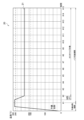
- FIG. 4 is a graph schematically showing an example of a heating profile.
- the horizontal axis of the graph 20 is time.
- the vertical axis of graph 20 is temperature.
- a line 21 shows the time series transition of the target temperature.
- the target temperature rapidly rises to around 300° C. after heating starts, then decreases to around 230° C. and is maintained until the end.
- power supply to the heating unit 121 is interrupted and heating is turned off.
- the timings at which puffs are performed from the first to the 15th time (hereinafter also referred to as puff timings) are displayed as #1 to #15.
- the puff timing may be set in advance.
- the time until the first puff timing is a preheating period, and 15 puff timings are set in the subsequent puffable period.
- the range from the second puff timing to the 15th puff timing is subject to customization, and changes in the target temperature at the first puff timing are restricted. This is because during the preheating period, it is desirable to rapidly raise the temperature of the heating section 121 and maintain it at a high temperature, and excessive temperature changes are not desirable.
- the temperature that can be set as the target temperature is limited to a range from a lower limit temperature of 190°C to an upper limit temperature of 290°C, and changes to temperatures exceeding the range are restricted. It's okay.
- the range of temperatures that can be set can be set as appropriate depending on the specifications of the heating section 121 and the like.
- the terminal device 200 controls the customization process.
- the customization process is a process of changing the heating profile used by the suction device 100.
- the terminal device 200 repeatedly executes the customization process until a heating profile that achieves the smoking taste desired by the user is generated. By repeating the customization process, the heating profile can be gradually brought closer to the ideal heating profile that achieves the user's desired smoking taste.
- the customization process includes generating a customization screen.
- the customization screen is a display image that displays an operation target for setting a target temperature included in the heating profile used by the suction device 100.
- the customization process includes changing the target temperature included in the heating profile in accordance with the user's operation on the operation target displayed on the generated customization screen.
- the flavor can be enhanced, and by lowering the target temperature, the flavor can be weakened.
- the user can gradually change the heating profile so as to approach the desired smoking taste while repeating operations on the operation target displayed on the customization screen.
- An example of the customization screen will be described with reference to FIG. 5.
- FIG. 5 is a diagram showing an example of a customization screen according to this embodiment.
- the customization screen 30 includes an axis 32 (32-1 to 312-15) on which points 31 (31-1 to 31-15) are movably arranged.
- Point 31 is an example of an object to be operated by the user.
- the position on the axis 32 corresponds to the value (ie, temperature) set as the target temperature. That is, the temperature corresponding to the position of point 31 is set as the target temperature.
- the user can change the target temperature included in the heating profile.
- the customization screen 30 includes a plurality of axes 32.
- Each of the multiple axes 32 corresponds to each of the multiple puff timings.
- the control unit 260 sets the target temperature at each of the plurality of puff timings based on the position of the point 31 on each of the plurality of axes 32.
- axis 32-3 corresponds to the third puff timing. Therefore, the control unit 260 sets the target temperature at the third puff timing based on the position of the point 31-3 on the axis 32-3.
- Terminal device 200 may display customization screen 30 and accept user operations during the heating session, or may display customization screen 30 and accept user operations after the heating session ends. According to this configuration, the user can customize the heating profile so that the smoking taste at each puff timing is as desired.
- the terminal device 200 changes the target temperature based on the position of the point 31 on the axis 32. More specifically, in the customization process, the terminal device 200 adds or subtracts a second value corresponding to the distance between the reference position and the position of the point 31 to or from a reference value corresponding to the reference position on the axis 32. , set as the target temperature.
- the terminal device 200 sets a value obtained by adding the second value to the first value as the target temperature.
- the terminal device 200 sets a value obtained by subtracting the second value from the first value as the target temperature.
- the first value corresponds to the target temperature before the change.
- the second value corresponds to the amount of change from the target temperature before change. That is, the terminal device 200 changes the target temperature more greatly as the position of the point 31 is farther from the reference position, and changes the target temperature smaller as the position of the point 31 is closer to the reference position. According to this configuration, the user can intuitively and easily change the target temperature.
- the point 31 can be moved on the axis 32 in units of a predetermined distance.
- the shaft 32 has seven scales, and the point 31 is located at the center scale and can be moved up and down to three scales. The user can set the target temperature by positioning the point 31 on any of the seven scales.
- the terminal device 200 sets a method for changing the target temperature in the next customization process based on the content of the target temperature change in the previous customization process.
- the method of changing the target temperature in the next customization process can be optimized according to the details of the change in the target temperature in the previous customization process. This makes it possible to improve usability regarding customization of the heating profile.
- the terminal device 200 determines the position on the axis 32 in the next customization process and the temperature that will be set as the target temperature when the point 31 is located at that position, based on the change in the target temperature in the previous customization process.
- Set the correspondence relationship with That is, the terminal device 200 updates the correspondence between the position on the axis 32 and the temperature corresponding to the position based on how much the target temperature was raised or lowered in the previous customization process.
- the above-mentioned correspondence relationship in the next customization process is updated in accordance with the user's intention, such as wanting to change the target temperature largely or in detail, as inferred from the content of changes in the target temperature in the previous customization process. can do. Therefore, it is possible to reach a heating profile that achieves the desired smoking taste of the user with fewer repetitions of the customization process.
- the terminal device 200 sets the first value in the next customization process based on the target temperature set in the previous customization process. More specifically, the terminal device 200 sets the target temperature set in the previous customization process as the first value in the next customization process. For example, the terminal device 200 sets the first value set for a certain puff timing as the target temperature set for the puff timing in the previous customization process. According to this configuration, in the process of repeating the customization process, it is possible to repeatedly change the target temperature based on the previously set target temperature. Note that the terminal device 200 sets an initial value as the first value in the first customization process.
- the initial position of the point 31 on the customization screen 30 is the reference position on the axis 32.
- the reference position is a position corresponding to the first value, that is, the target temperature before change. Therefore, if the position of point 31 after receiving the user operation remains at the reference position, terminal device 200 does not change the target temperature.
- the terminal device 200 changes the target temperature in accordance with the movement. According to this configuration, the user can intuitively change the heating profile by moving the point 31 from the reference position.
- the reference position may be the center of the axis 32. In the example shown in FIG. 5, the reference position is the center of the shaft 32 in the vertical direction. Then, the terminal device 200 makes the target temperature higher than before the change when the position of the point 31 is moved above the center of the axis 32, and when the position of the point 31 is moved below the center of the axis 32. If the change occurs, set the target temperature lower than before the change. According to this configuration, the user can raise or lower the target temperature by moving the point 31 up or down from the reference position.
- the terminal device 200 sets a second value per unit distance in the next customization process based on the amount of change in the target temperature in the previous customization process. Specifically, the terminal device 200 sets the amount of temperature change per scale of the axis 32 in the next customization process based on the amount of change in the target temperature in the previous customization process. The amount of temperature change per scale of the axis 32 is also referred to as resolution below.
- the terminal device 200 sets a larger resolution in the next customization process as the amount of change in the target temperature in the previous customization process is larger.
- the terminal device 200 sets the resolution in the next customization process to be smaller as the amount of change in the target temperature in the previous customization process is smaller.
- a typical flow when customizing a heating profile is to roughly change the target temperature to bring the taste closer to the ideal, and then fine-tune the taste by changing the target temperature in small steps.
- by adjusting the resolution according to the amount of change in the target temperature in the previous customization process it is possible to automatically customize the heating profile along the above typical flow.
- the terminal device 200 may set the resolution in the next customization process so that an integral multiple of the resolution in the next customization process matches the amount of change in the target temperature in the previous customization process.
- the terminal device 200 may set the resolution in the next customization process to a value obtained by dividing the amount of change in the target temperature in the previous customization process by an integer. It is desirable that the integer here remains unchanged during repeated customization processing. According to this configuration, the user can change the target temperature in the next customization process based on the amount of change in the target temperature in the previous customization process.
- the terminal device 200 may set the resolution based on the following formula.
- ⁇ T resolution.
- n is the number of repetitions of the next customization process.
- T n-1 is the target temperature set in the previous customization process.
- T n-2 is the target temperature set in the previous customization process.
- FIG. 6 is a diagram showing the correspondence between the position on the axis 32 and the temperature in the next customization process when the target temperature has been raised in the previous customization process.
- the terminal device 200 sets the target temperature T n-1 set in the previous customization process as the temperature corresponding to the scale at the center of the axis 32.
- the terminal device 200 sets T n-1 + ⁇ T as the temperature corresponding to the scale one scale above the center of the axis 32, and sets T n-1 +2 ⁇ T as the temperature corresponding to the scale two scales above, T n-1 +3 ⁇ T is set as the temperature corresponding to the third scale above.
- the terminal device 200 sets T n-1 - ⁇ T as the temperature corresponding to the scale one scale below the center of the axis 32, and sets T n-1 -2 ⁇ T as the temperature corresponding to the scale two scales below. Then, T n-1 -3 ⁇ T is set as the temperature corresponding to the third lower scale. Note that the resolution ⁇ T is calculated by the above formula (1), and since T n-1 > T n-2 , T n-1 -2 ⁇ T is equal to T n-2 .
- FIG. 7 is a diagram showing the correspondence between the position on the axis 32 and the temperature in the next customization process when the target temperature has been lowered in the previous customization process.
- the terminal device 200 sets the target temperature T n-1 set in the previous customization process as the temperature corresponding to the scale at the center of the axis 32.
- the terminal device 200 sets T n-1 + ⁇ T as the temperature corresponding to the scale one scale above the center of the axis 32, and sets T n-1 +2 ⁇ T as the temperature corresponding to the scale two scales above, T n-1 +3 ⁇ T is set as the temperature corresponding to the third scale above.
- the terminal device 200 sets T n-1 - ⁇ T as the temperature corresponding to the scale one scale below the center of the axis 32, and sets T n-1 -2 ⁇ T as the temperature corresponding to the scale two scales below. Then, T n-1 -3 ⁇ T is set as the temperature corresponding to the third lower scale. Note that the resolution ⁇ T is calculated by the above formula (1), and since T n-1 ⁇ T n-2 , T n-1 +2 ⁇ T is equal to T n-2 .
- twice the resolution ⁇ T in the next customization process matches the amount of change in the target temperature in the previous customization process. Therefore, by moving the point 31 by two scales from the center of the axis 32, the target temperature can be changed by the same amount as the previous time. Therefore, by moving the point 31 up or down by two scales from the center of the axis 32, it is possible to change the target temperature in the same way as before or cancel the previous change in the target temperature. .
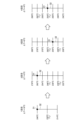
- FIG. 8 is a diagram for explaining a first specific example of updating the correspondence between the scale of the axis 32 and the temperature corresponding to one puff timing.
- This figure shows an example where the target temperature is raised in the second customization process and the third customization process.
- three scales are set on the axis 32
- seven scales are set on the axis 32. In this way, by reducing the number of scale marks it is possible to make the operation easier to understand, and by increasing the number of scale marks it is possible to make detailed customization possible.
- the terminal device 200 sets the temperature corresponding to the scale at the center of the axis 32 to 230°C, which is the initial value T0 , and sets the resolution ⁇ T to 16°C. That is, as shown in FIG. 8, the terminal device 200 sets the scale of the axis 32 to 246° C., 230° C., and 214° C. in order from the top.
- the terminal device 200 changes the target temperature from 230°C to 246°C.
- the terminal device 200 sets the temperature corresponding to the center scale of the axis 32 to 246°C, which is the target temperature T1 set in the first customization process, and ), the resolution ⁇ T is set to 8°C. That is, as shown in FIG. 8, the terminal device 200 sets the scale of the axis 32 to 270°C, 262°C, 254°C, 246°C, 238°C, 230°C, and 222°C in order from the top.
- the terminal device 200 changes the target temperature from 246°C to 270°C.
- the terminal device 200 sets the temperature corresponding to the scale at the center of the axis 32 to 270°C, which is the target temperature T2 set in the second customization process, and ), the resolution ⁇ T is set to 12°C. That is, as shown in FIG. 8, the terminal device 200 sets the scale of the axis 32 to 306°C, 294°C, 282°C, 270°C, 258°C, 246°C, and 234°C in order from the top.
- the terminal device 200 changes the target temperature from 270°C to 282°C.
- the terminal device 200 sets the temperature corresponding to the center scale of the axis 32 to 282°C, which is the target temperature T3 set in the third customization process, and ), the resolution ⁇ T is set to 6°C. That is, as shown in FIG. 8, the terminal device 200 sets the scale of the axis 32 to 302°C, 296°C, 288°C, 282°C, 276°C, 270°C, and 264°C in order from the top.
- the portion of the axis 32 that exceeds the upper limit temperature of 290° C. that can be set as the target temperature is displayed with a broken line. Then, movement of the point 31 to the broken line portion is restricted. According to this configuration, it is possible to clearly indicate to the user that setting a temperature higher than the upper limit temperature of 290° C. as the target temperature is restricted.
- FIG. 9 is a diagram for explaining a second specific example of updating the correspondence between the scale of the axis 32 corresponding to one puff timing and the temperature. This figure shows an example in which the target temperature is raised in the second customization process and lowered in the third customization process. The number of scale marks on the axis 32 from the first customization process to the fourth customization process is the same as in FIG. 8 .
- the terminal device 200 sets the temperature corresponding to the scale at the center of the axis 32 to 230°C, which is the initial value T0 , and sets the resolution ⁇ T to 16°C. That is, as shown in FIG. 9, the terminal device 200 sets the scale of the axis 32 to 246° C., 230° C., and 214° C. in order from the top.
- the terminal device 200 changes the target temperature from 230°C to 246°C.
- the terminal device 200 sets the temperature corresponding to the scale at the center of the axis 32 to 246°C, which is the target temperature T1 set in the first customization process, and uses the above formula ( Based on 1), the resolution ⁇ T is set to 8°C. That is, as shown in FIG. 9, the terminal device 200 sets the scale of the axis 32 to 270°C, 262°C, 254°C, 246°C, 238°C, 230°C, and 222°C in order from the top.
- the terminal device 200 changes the target temperature from 246°C to 262°C.
- the terminal device 200 sets the temperature corresponding to the scale at the center of the axis 32 to 262°C, which is the target temperature T2 set in the second customization process, and ), the resolution ⁇ T is set to 8°C. That is, as shown in FIG. 9, the terminal device 200 sets the scale of the axis 32 to 286°C, 278°C, 270°C, 262°C, 254°C, 246°C, and 238°C in order from the top. In the third customization process, the user moves the point 31 from the center of the axis 32 to one scale below. Therefore, the terminal device 200 changes the target temperature from 262°C to 254°C.
- the terminal device 200 sets the temperature corresponding to the center scale of the axis 32 to 254°C, which is the target temperature T3 set in the third customization process, and ), the resolution ⁇ T is set to 4°C. That is, as shown in FIG. 9, the terminal device 200 sets the scale of the axis 32 to 266°C, 262°C, 258°C, 254°C, 250°C, 246°C, and 242°C in order from the top.
- FIG. 10 is a diagram for explaining a third specific example of updating the correspondence between the scale of the axis 32 and the temperature corresponding to one puff timing. This figure shows an example where the target temperature is lowered in the second customization process and the third customization process. The number of scale marks on the axis 32 from the first customization process to the fourth customization process is the same as in FIG. 8 .
- the terminal device 200 sets the temperature corresponding to the scale at the center of the axis 32 to 230°C, which is the initial value T0 , and sets the resolution ⁇ T to 16°C. That is, as shown in FIG. 10, the terminal device 200 sets the scale of the axis 32 to 246° C., 230° C., and 214° C. in order from the top.
- the terminal device 200 changes the target temperature from 230°C to 246°C.
- the terminal device 200 sets the temperature corresponding to the center scale of the axis 32 to 246°C, which is the target temperature T1 set in the first customization process, and ), the resolution ⁇ T is set to 8°C. That is, as shown in FIG. 10, the terminal device 200 sets the scale of the axis 32 to 270°C, 262°C, 254°C, 246°C, 238°C, 230°C, and 222°C in order from the top.
- the user moves the point 31 to a scale three positions below the center of the axis 32. Therefore, the terminal device 200 changes the target temperature from 246°C to 222°C.
- the terminal device 200 sets the temperature corresponding to the scale at the center of the axis 32 to 222°C, which is the target temperature T2 set in the second customization process, and ), the resolution ⁇ T is set to 12°C. That is, as shown in FIG. 10, the terminal device 200 sets the scale of the axis 32 to 258° C., 246° C., 234° C., 222° C., 210° C., 198° C., and 186° C. in order from the top. In the third customization process, the user moves the point 31 from the center of the axis 32 to two scale marks below. Therefore, the terminal device 200 changes the target temperature from 222°C to 198°C.
- the terminal device 200 sets the temperature corresponding to the center scale of the axis 32 to 198°C, which is the target temperature T3 set in the third customization process, and ), the resolution ⁇ T is set to 12°C. That is, as shown in FIG. 10, the terminal device 200 sets the scale of the axis 32 to 234°C, 222°C, 210°C, 198°C, 186°C, 174°C, and 162°C in order from the top.
- the portion of the axis 32 that is below the lower limit temperature of 190° C. that can be set as the target temperature is displayed with a broken line. Then, movement of the point 31 to the broken line portion is restricted. According to this configuration, it becomes possible to clearly indicate to the user that setting a temperature below the lower limit temperature of 190° C. as the target temperature is restricted.
- FIG. 11 is a diagram for explaining a fourth specific example of updating the correspondence between the scale of the axis 32 and the temperature corresponding to one puff timing. This figure shows an example in which the target temperature is lowered in the second customization process and raised in the third customization process. The number of scale marks on the axis 32 from the first customization process to the fourth customization process is the same as in FIG. 8 .
- the terminal device 200 sets the temperature corresponding to the scale at the center of the axis 32 to 230°C, which is the initial value T0 , and sets the resolution ⁇ T to 16°C. That is, as shown in FIG. 11, the terminal device 200 sets the scale of the axis 32 to 246° C., 230° C., and 214° C. in order from the top.
- the terminal device 200 changes the target temperature from 230°C to 246°C.
- the terminal device 200 sets the temperature corresponding to the center scale of the axis 32 to 246°C, which is the target temperature T1 set in the first customization process, and ), the resolution ⁇ T is set to 8°C. That is, as shown in FIG. 11, the terminal device 200 sets the scale of the axis 32 to 270°C, 262°C, 254°C, 246°C, 238°C, 230°C, and 222°C from the top.
- the terminal device 200 changes the target temperature from 246°C to 238°C.
- the terminal device 200 sets the temperature corresponding to the center scale of the axis 32 to 238°C, which is the target temperature T2 set in the second customization process, and ), the resolution ⁇ T is set to 4°C. That is, as shown in FIG. 11, the terminal device 200 sets the scale of the axis 32 to 250°C, 246°C, 242°C, 238°C, 234°C, 230°C, and 226°C in order from the top.
- the terminal device 200 changes the target temperature from 238°C to 242°C.
- the terminal device 200 sets the temperature corresponding to the center scale of the axis 32 to 242°C, which is the target temperature T3 set in the third customization process, and ), the resolution ⁇ T is set to 2°C. That is, as shown in FIG. 11, the terminal device 200 sets the scale of the axis 32 to 248° C., 246° C., 244° C., 242° C., 240° C., 238° C., and 236° C. in order from the top.
- the temperature and resolution ⁇ T corresponding to each scale of the axis 32 may be displayed or hidden on the customization screen 30.
- the temperature and resolution ⁇ T corresponding to each scale of the axis 32 at each puff timing are not displayed.
- one point 31 is displayed on one axis 32 on the customization screen 30, the present invention is not limited to such an example.
- one axis 32 in addition to the point 31 that accepts user operations, there is also a point corresponding to the target temperature T n-1 set in the previous customization process, and furthermore, a point corresponding to the target temperature T n-1 set in the previous customization process.
- a point corresponding to n-2 may be displayed. In that case, the user can change the target temperature while keeping track of the change history.
- FIG. 12 is a flowchart illustrating an example of the flow of processing executed in the terminal device 200 according to the present embodiment.
- the control unit 260 detects the start of heating based on the heating profile (step S102). For example, when suction device 100 starts heating based on the heating profile, it may transmit information indicating that heating has started to terminal device 200. Based on the reception of such information, the control unit 260 can detect the start of heating based on the heating profile.
- the control unit 260 sets the temperature and resolution corresponding to the scale at the center of the axis 32, depending on the change in the target temperature in the previous customization process (step S104). At this time, the control unit 260 sets the target temperature set in the previous customization process to the temperature corresponding to the scale at the center of the axis 32. Then, the control unit 260 sets the resolution based on the amount of change in the target temperature in the previous customization process. For each puff timing, the temperature and/or resolution corresponding to the center scale of axis 32 may be different.
- control unit 260 displays the customization screen 30 and accepts a user operation to move the point 31 on the axis 32 corresponding to each puff timing (step S106).
- the control unit 260 causes the output unit 220 to display the customization screen 30 during the heating session, prompting the user to puff each time the puff timing arrives, and then displaying a screen prompting the user to move the point 31 according to the smoking taste. may be controlled.
- the control unit 260 changes the target temperature at each puff timing based on the position of the point 31 on the axis 32 corresponding to each puff timing (step S108).
- the control unit 260 adds a temperature obtained by multiplying the number of scales moved by the resolution to the target temperature set in the previous customization process. This temperature is set as the target temperature.
- the control unit 260 controls the temperature by multiplying the number of scales moved by the resolution from the target temperature set in the previous customization process. The temperature obtained by subtracting is set as the target temperature.
- the control unit 260 continues to set the target temperature set in the previous customization process as the target temperature.
- control unit 260 controls the communication unit 240 to transmit the changed heating profile to the suction device 100 (step S110). Thereby, the suction device 100 can perform heating based on the changed heating profile from next time onwards.
- the processing related to steps S102 to S110 described above corresponds to the customization processing.
- the control unit 260 determines whether the termination condition is satisfied (step S112).
- An example of the termination condition is that the user has instructed to terminate the customization process.
- Another example of a termination condition is that point 31 was not moved from the center scale of axis 32 for all puff timings. According to this process, the customization process is repeated until the change in target temperature is converged, and it becomes possible for the user to generate a heating profile that achieves the desired smoking taste.
- the terminal device 200 may change the time until the first puff timing. Specifically, when the position of the point 31-1 on the axis 32-1 corresponding to the first puff timing is raised, the terminal device 200 extends the time until the first puff timing. Good too. In this case, similar to the case of increasing the target temperature, it is possible to enhance the taste. On the other hand, if the position of the point 31-1 on the axis 32-1 corresponding to the first puff timing is lowered, the terminal device 200 may shorten the time until the first puff timing is reached. In this case, similar to the case of lowering the target temperature, it is possible to weaken the smoking taste.
- the target temperature at the second puff timing is preferably used as the temperature at which heating is turned from heating OFF to heating ON (hereinafter also referred to as heating restart temperature).
- heating restart temperature the temperature at which heating is turned from heating OFF to heating ON
- FIG. 13 is a diagram for explaining the target temperature at the second puff timing. This figure shows a case where the target temperature at the second puff timing is changed from 230°C to 246°C.
- Graph 40A shows the heating profile before change.
- the line 41A shows the time series transition of the target temperature.
- Graph 40B shows a heating profile when the target temperature is changed to 246°C and the heating restart temperature remains unchanged at 230°C.
- a line 41B shows the time series transition of the target temperature.
- Graph 40C shows a heating profile when the target temperature and heating restart temperature are changed to 246°C.
- a line 41C indicates a time series transition of the target temperature.
- the heating restart temperature remains at 230°C
- the temperature of the heating section 121 once drops to 230°C and then rises to 246°C, which has the effect of improving the smoking taste at the second puff timing. is thin.
- the heating restart temperature is changed to 246°C
- the temperature of the heating section 121 is maintained at 246°C as the lower limit, so the smoking taste at the second puff timing can be greatly improved. It becomes possible.
- the target temperature set in the previous customization process is set as the temperature corresponding to the scale at the center of the axis 32, but the present invention is not limited to such an example.
- the terminal device 200 may set a value different from the target temperature set in the previous customization process as the first value in the next customization process. For example, the terminal device 200 may set the first value for a certain puff timing as the average value of the target temperatures set for the puff timing and the puff timings before and after the puff timing in the previous customization process.
- temperatures that can be set as the target temperature are set as discrete values.
- the temperature that can be set as the target temperature may be a continuous value. That is, the point 31 may be movable between the scales on the axis 32 as well.
- the terminal device 200 may display a portion of the axis 32 that corresponds to a temperature that can be set as a target temperature in a different display manner than a portion of the axis 32 that corresponds to a temperature that cannot be set. All you have to do is do it.
- the difference in these display modes is not limited to the difference between solid lines and broken lines.
- the terminal device 200 may have different colors, thicknesses, shadings, etc.
- the heating section 121 is configured as a heating resistor and generates heat by electric resistance, but the present invention is not limited to such an example.
- the heating unit 121 may include an electromagnetic induction source such as a coil that generates a magnetic field, and a susceptor that generates heat by induction heating, and the stick-shaped base material 150 may be heated by the susceptor.
- the control unit 116 applies an alternating current to the electromagnetic induction source to generate an alternating magnetic field, and causes the alternating magnetic field to enter the susceptor, thereby causing the susceptor to generate heat.
- the temperature at which the aerosol source is heated which is controlled based on the heating profile, will be the temperature of the susceptor.
- the temperature of the susceptor can be estimated based on the electrical resistance value of the electromagnetic induction source.
- the parameter related to the temperature at which the aerosol source is heated which is defined in the heating profile, is the target temperature of the heating section 121, but the present invention is not limited to such an example.
- Parameters related to the temperature at which the aerosol source is heated include the electrical resistance value of the heating section 121 in addition to the temperature itself of the heating section 121 described in the above embodiment.
- the suction device 100 includes an electromagnetic induction source instead of the heating unit 121
- the parameters related to the temperature for heating the aerosol source specified in the heating profile include the temperature of the susceptor, the electrical resistance value of the electromagnetic induction source, etc. Target values can be mentioned.
- the suction device 100 may be configured as a so-called liquid atomization type aerosol generation device that generates aerosol by heating and atomizing a liquid aerosol source.
- the present invention is also applicable to liquid atomization type aerosol generation devices.
- Each device described in this specification may be realized as a single device, or a part or all of it may be realized as a separate device.
- the control unit 260 of the terminal device 200 may be included in a device such as a server connected to the terminal device 200 via a network or the like. That is, customization of the heating profile may be performed by a server on the cloud based on a user operation input into the terminal device 200.
- each device described in this specification may be realized using software, hardware, or a combination of software and hardware.
- a program constituting the software is stored in advance, for example, in a recording medium (specifically, a computer-readable non-temporary storage medium) provided inside or outside each device.
- each program is read into the RAM when executed by a computer that controls each device described in this specification, and is executed by a processing circuit such as a CPU.
- the recording medium is, for example, a magnetic disk, an optical disk, a magneto-optical disk, a flash memory, or the like.
- the above computer program may be distributed, for example, via a network, without using a recording medium.
- the above-mentioned computer may be an application-specific integrated circuit such as an ASIC, a general-purpose processor that executes functions by loading a software program, or a computer on a server used for cloud computing. Furthermore, a series of processes performed by each device described in this specification may be distributed and processed by multiple computers.
- the parameters included in the control information are used by a suction device that generates an aerosol by heating an aerosol source included in a base material based on control information that defines parameters regarding the temperature at which the aerosol source is heated.
- Information processing device is used by a suction device that generates an aerosol by heating an aerosol source included in a base material based on control information that defines parameters regarding the temperature at which the aerosol source is heated.
- the display image includes an axis on which the operation target is movably arranged
- the control unit includes: changing the parameters based on the position of the operation target on the axis in the customization process; Based on the changes to the parameters in the previous customization process, determine the correspondence between the position on the axis in the next customization process and the value set as the parameter when the operation target is located at the position. set, The information processing device according to (1) above.
- the control unit includes: In the customization process, a value obtained by adding or subtracting a second value corresponding to a difference between the reference position and the operation target position to a first value corresponding to the reference position on the axis is used as the parameter.
- the control unit sets the parameter set in the previous customization process to the first value in the next customization process;
- the control unit includes: In the customization process, a value obtained by adding or subtracting a second value corresponding to a distance between the reference position and the operation target position to a first value corresponding to the reference position on the axis is used as the parameter.
- Set setting the second value per unit distance in the next customization process based on a change amount of the parameter in the previous customization process; The information processing device according to any one of (2) to (4) above.
- the control unit sets the second value per unit distance in the next customization process to be larger as the amount of change in the parameter in the previous customization process is larger, and the control unit sets the second value per unit distance in the next customization process to a larger value, The smaller the amount, the smaller the second value per unit distance in the next customization process.
- the information processing device according to (5) above.
- the control unit adjusts the unit in the next customization process so that an integral multiple of the second value per unit distance in the next customization process matches the change amount of the parameter in the previous customization process. setting the second value per distance;
- the initial position of the operation target in the display image is the reference position on the axis; The information processing device according to any one of (3) to (7) above.
- the reference position is the center of the axis;
- the information processing device according to (8) above.
- the displayed image includes a plurality of axes, each of the plurality of axes corresponding to each of a plurality of puff timings,
- the control unit sets the parameters at each of the plurality of puff timings based on the position of the operation target on each of the plurality of axes.
- the information processing device according to any one of (2) to (9) above.
- the control unit causes a display mode of a portion of the axis corresponding to a value that can be set as the parameter to be different from a display mode of a portion of the axis that corresponds to a value that cannot be set.
- the information processing device according to any one of (2) to (10) above.
- the parameters included in the control information are used by a suction device that generates an aerosol by heating an aerosol source included in a base material based on control information that defines parameters regarding the temperature at which the aerosol source is heated.
- Controlling the customization process includes setting a method for changing the parameter in the next customization process based on the content of the change in the parameter in the previous customization process when repeatedly executing the customization process. include, Information processing method.
- the parameters included in the control information are used by a suction device that generates an aerosol by heating an aerosol source included in a base material based on control information that defines parameters regarding the temperature at which the aerosol source is heated.
Landscapes
- Engineering & Computer Science (AREA)
- Human Computer Interaction (AREA)
- General Engineering & Computer Science (AREA)
- Theoretical Computer Science (AREA)
- Physics & Mathematics (AREA)
- General Physics & Mathematics (AREA)
- Manufacturing & Machinery (AREA)
- Automation & Control Theory (AREA)
- Computer Networks & Wireless Communication (AREA)
- User Interface Of Digital Computer (AREA)
Abstract
Description
(1)システムの構成例
図1は、一実施形態に係るシステム1の構成例を説明するための図である。図1に示すように、システム1は、吸引装置100、及び端末装置200を含む。
図2は、本実施形態に係る吸引装置の構成例を模式的に示す模式図である。図2に示すように、吸引装置100は、電源部111、センサ部112、通知部113、記憶部114、通信部115、制御部116、加熱部121、保持部140、及び断熱部144を含む。
図3は、本実施形態に係る端末装置200の構成例を示すブロック図である。図3に示すように、端末装置200は、入力部210、出力部220、検出部230、通信部240、記憶部250、及び制御部260を含む。
(1)加熱プロファイル
制御部116は、加熱プロファイルに基づいて、加熱部121の動作を制御する。加熱部121の動作の制御は、電源部111から加熱部121への給電を制御することにより、実現される。加熱部121は、電源部111から供給された電力を使用してスティック型基材150を加熱する。
端末装置200(例えば、制御部260)は、カスタマイズ処理を制御する。カスタマイズ処理とは、吸引装置100により使用される加熱プロファイルを変更する処理である。端末装置200は、ユーザの思い通りの喫味を実現する加熱プロファイルが生成されるまで、カスタマイズ処理を繰り返し実行する。カスタマイズ処理を繰り返すことで、加熱プロファイルを、ユーザの思い通りの喫味を実現する理想の加熱プロファイルに徐々に近づけることができる。

以上、前回のカスタマイズ処理における目標温度の変更内容に基づく、次回のカスタマイズ処理における目標温度の変更方法について説明した。以下、図8~図11を参照しながら、具体例を説明する。
図8は、ある1つのパフタイミングに対応する軸32の目盛りと温度との対応関係を更新する第1の具体例を説明するための図である。本図では、2回目のカスタマイズ処理及び3回目のカスタマイズ処理において目標温度が上げられた場合の例が図示されている。1回目のカスタマイズ処理においては軸32に3つの目盛りが設定され、2回目以降のカスタマイズ処理においては軸32に7つの目盛りが設定されている。このように、目盛りの数を少なくすることで操作を分かりやすくしたり、目盛りの数を多くすることで細かなカスタマイズを可能にしたりすることができる。
図9は、ある1つのパフタイミングに対応する軸32の目盛りと温度との対応関係を更新する第2の具体例を説明するための図である。本図では、2回目のカスタマイズ処理において目標温度が上げられ3回目のカスタマイズ処理において目標温度が下げられた場合の例が図示されている。1回目のカスタマイズ処理から4回目のカスタマイズ処理における軸32上の目盛りの数については、図8と同様である。
図10は、ある1つのパフタイミングに対応する軸32の目盛りと温度との対応関係を更新する第3の具体例を説明するための図である。本図では、2回目のカスタマイズ処理及び3回目のカスタマイズ処理において目標温度が下げられた場合の例が図示されている。1回目のカスタマイズ処理から4回目のカスタマイズ処理における軸32上の目盛りの数については、図8と同様である。
図11は、ある1つのパフタイミングに対応する軸32の目盛りと温度との対応関係を更新する第4の具体例を説明するための図である。本図では、2回目のカスタマイズ処理において目標温度が下げられ3回目のカスタマイズ処理において目標温度が上げられた場合の例が図示されている。1回目のカスタマイズ処理から4回目のカスタマイズ処理における軸32上の目盛りの数については、図8と同様である。
軸32の各目盛りに対応する温度及び分解能ΔTは、カスタマイズ画面30において表示されてもよいし、非表示であってもよい。例えば、図5に示したカスタマイズ画面30では、各パフタイミングにおける軸32の各目盛りに対応する温度及び分解能ΔTは非表示である。
以下、図12を参照しながら、本実施形態に係る端末装置200において実行される処理の流れについて説明する。図12は、本実施形態に係る端末装置200において実行される処理の流れの一例を示すフローチャートである。
以上、添付図面を参照しながら本発明の好適な実施形態について詳細に説明したが、本発明はかかる例に限定されない。本発明の属する技術の分野における通常の知識を有する者であれば、請求の範囲に記載された技術的思想の範疇内において、各種の変更例または修正例に想到し得ることは明らかであり、これらについても、当然に本発明の技術的範囲に属するものと了解される。
(1)
基材に含まれるエアロゾル源を、前記エアロゾル源を加熱する温度に関するパラメータを規定する制御情報に基づいて加熱することでエアロゾルを生成する吸引装置により使用される、前記制御情報に含まれる前記パラメータを設定するための操作対象を表示する表示画像を生成することと、
生成した前記表示画像に表示された前記操作対象に対するユーザ操作に応じて、前記制御情報に含まれる前記パラメータを変更することと、
を含むカスタマイズ処理を制御する制御部、
を備え、
前記制御部は、前記カスタマイズ処理を繰り返し実行する際に、前回の前記カスタマイズ処理における前記パラメータの変更内容に基づいて、次回の前記カスタマイズ処理における前記パラメータの変更方法を設定する、
情報処理装置。
(2)
前記表示画像は、前記操作対象が移動可能に配置された軸を含み、
前記制御部は、
前記カスタマイズ処理において前記軸上の前記操作対象の位置に基づいて前記パラメータを変更し、
前回の前記カスタマイズ処理における前記パラメータの変更内容に基づいて、次回の前記カスタマイズ処理における前記軸上の位置と当該位置に前記操作対象が位置する場合に前記パラメータとして設定される値との対応関係を設定する、
前記(1)に記載の情報処理装置。
(3)
前記制御部は、
前記カスタマイズ処理において、前記軸上の基準位置に対応する第1の値に、前記基準位置と前記操作対象の位置との差分に対応する第2の値を加算又は減算した値を、前記パラメータとして設定し、
前回の前記カスタマイズ処理において設定された前記パラメータに基づいて、次回の前記カスタマイズ処理における前記第1の値を設定する、
前記(2)に記載の情報処理装置。
(4)
前記制御部は、前回の前記カスタマイズ処理において設定された前記パラメータを、次回の前記カスタマイズ処理における前記第1の値に設定する、
前記(3)に記載の情報処理装置。
(5)
前記制御部は、
前記カスタマイズ処理において、前記軸上の基準位置に対応する第1の値に、前記基準位置と前記操作対象の位置との距離に対応する第2の値を加算又は減算した値を、前記パラメータとして設定し、
前回の前記カスタマイズ処理における前記パラメータの変更量に基づいて、次回の前記カスタマイズ処理における単位距離当たりの前記第2の値を設定する、
前記(2)~(4)のいずれか一項に記載の情報処理装置。
(6)
前記制御部は、前回の前記カスタマイズ処理における前記パラメータの変更量が大きいほど次回の前記カスタマイズ処理における前記単位距離当たりの前記第2の値を大きく設定し、前回の前記カスタマイズ処理における前記パラメータの変更量が小さいほど次回の前記カスタマイズ処理における前記単位距離当たりの前記第2の値を小さく設定する、
前記(5)に記載の情報処理装置。
(7)
前記制御部は、次回の前記カスタマイズ処理における前記単位距離当たりの前記第2の値の整数倍が、前回の前記カスタマイズ処理における前記パラメータの変更量に一致するよう、次回の前記カスタマイズ処理における前記単位距離当たりの前記第2の値を設定する、
前記(5)又は(6)に記載の情報処理装置。
(8)
前記表示画像における前記操作対象の初期位置は、前記軸上の前記基準位置である、
前記(3)~(7)のいずれか一項に記載の情報処理装置。
(9)
前記基準位置は、前記軸の中心である、
前記(8)に記載の情報処理装置。
(10)
前記表示画像は、複数の前記軸を含み、複数の前記軸の各々は複数のパフタイミングの各々に対応し、
前記制御部は、複数の前記軸の各々における前記操作対象の位置に基づいて、複数の前記パフタイミングの各々における前記パラメータを設定する、
前記(2)~(9)のいずれか一項に記載の情報処理装置。
(11)
前記制御部は、前記表示画像において、前記軸のうち前記パラメータとして設定可能な値に対応する部分の表示態様と前記軸のうち設定不可能な値に対応する部分の表示態様とを異ならせる、
前記(2)~(10)のいずれか一項に記載の情報処理装置。
(12)
基材に含まれるエアロゾル源を、前記エアロゾル源を加熱する温度に関するパラメータを規定する制御情報に基づいて加熱することでエアロゾルを生成する吸引装置により使用される、前記制御情報に含まれる前記パラメータを設定するための操作対象を表示する表示画像を生成することと、
生成した前記表示画像に表示された前記操作対象に対するユーザ操作に応じて、前記制御情報に含まれる前記パラメータを変更することと、
を含むカスタマイズ処理を制御することを含み、
前記カスタマイズ処理を制御することは、前記カスタマイズ処理を繰り返し実行する際に、前回の前記カスタマイズ処理における前記パラメータの変更内容に基づいて、次回の前記カスタマイズ処理における前記パラメータの変更方法を設定することを含む、
情報処理方法。
(13)
コンピュータを、
基材に含まれるエアロゾル源を、前記エアロゾル源を加熱する温度に関するパラメータを規定する制御情報に基づいて加熱することでエアロゾルを生成する吸引装置により使用される、前記制御情報に含まれる前記パラメータを設定するための操作対象を表示する表示画像を生成することと、
生成した前記表示画像に表示された前記操作対象に対するユーザ操作に応じて、前記制御情報に含まれる前記パラメータを変更することと、
を含むカスタマイズ処理を制御する制御部、
として機能させ、
前記制御部は、前記カスタマイズ処理を繰り返し実行する際に、前回の前記カスタマイズ処理における前記パラメータの変更内容に基づいて、次回の前記カスタマイズ処理における前記パラメータの変更方法を設定する、
プログラム。
100 吸引装置
111 電源部
112 センサ部
113 通知部
114 記憶部
115 通信部
116 制御部
121 加熱部
140 保持部
141 内部空間
142 開口
143 底部
144 断熱部
150 スティック型基材
151 基材部
152 吸口部
200 端末装置
210 入力部
220 出力部
230 検出部
240 通信部
250 記憶部
260 制御部
30 カスタマイズ画面
31 点
32 軸
Claims (13)
- 基材に含まれるエアロゾル源を、前記エアロゾル源を加熱する温度に関するパラメータを規定する制御情報に基づいて加熱することでエアロゾルを生成する吸引装置により使用される、前記制御情報に含まれる前記パラメータを設定するための操作対象を表示する表示画像を生成することと、
生成した前記表示画像に表示された前記操作対象に対するユーザ操作に応じて、前記制御情報に含まれる前記パラメータを変更することと、
を含むカスタマイズ処理を制御する制御部、
を備え、
前記制御部は、前記カスタマイズ処理を繰り返し実行する際に、前回の前記カスタマイズ処理における前記パラメータの変更内容に基づいて、次回の前記カスタマイズ処理における前記パラメータの変更方法を設定する、
情報処理装置。 - 前記表示画像は、前記操作対象が移動可能に配置された軸を含み、
前記制御部は、
前記カスタマイズ処理において前記軸上の前記操作対象の位置に基づいて前記パラメータを変更し、
前回の前記カスタマイズ処理における前記パラメータの変更内容に基づいて、次回の前記カスタマイズ処理における前記軸上の位置と当該位置に前記操作対象が位置する場合に前記パラメータとして設定される値との対応関係を設定する、
請求項1に記載の情報処理装置。 - 前記制御部は、
前記カスタマイズ処理において、前記軸上の基準位置に対応する第1の値に、前記基準位置と前記操作対象の位置との差分に対応する第2の値を加算又は減算した値を、前記パラメータとして設定し、
前回の前記カスタマイズ処理において設定された前記パラメータに基づいて、次回の前記カスタマイズ処理における前記第1の値を設定する、
請求項2に記載の情報処理装置。 - 前記制御部は、前回の前記カスタマイズ処理において設定された前記パラメータを、次回の前記カスタマイズ処理における前記第1の値に設定する、
請求項3に記載の情報処理装置。 - 前記制御部は、
前記カスタマイズ処理において、前記軸上の基準位置に対応する第1の値に、前記基準位置と前記操作対象の位置との距離に対応する第2の値を加算又は減算した値を、前記パラメータとして設定し、
前回の前記カスタマイズ処理における前記パラメータの変更量に基づいて、次回の前記カスタマイズ処理における単位距離当たりの前記第2の値を設定する、
請求項2~4のいずれか一項に記載の情報処理装置。 - 前記制御部は、前回の前記カスタマイズ処理における前記パラメータの変更量が大きいほど次回の前記カスタマイズ処理における前記単位距離当たりの前記第2の値を大きく設定し、前回の前記カスタマイズ処理における前記パラメータの変更量が小さいほど次回の前記カスタマイズ処理における前記単位距離当たりの前記第2の値を小さく設定する、
請求項5に記載の情報処理装置。 - 前記制御部は、次回の前記カスタマイズ処理における前記単位距離当たりの前記第2の値の整数倍が、前回の前記カスタマイズ処理における前記パラメータの変更量に一致するよう、次回の前記カスタマイズ処理における前記単位距離当たりの前記第2の値を設定する、
請求項5又は6に記載の情報処理装置。 - 前記表示画像における前記操作対象の初期位置は、前記軸上の前記基準位置である、
請求項3~7のいずれか一項に記載の情報処理装置。 - 前記基準位置は、前記軸の中心である、
請求項8に記載の情報処理装置。 - 前記表示画像は、複数の前記軸を含み、複数の前記軸の各々は複数のパフタイミングの各々に対応し、
前記制御部は、複数の前記軸の各々における前記操作対象の位置に基づいて、複数の前記パフタイミングの各々における前記パラメータを設定する、
請求項2~9のいずれか一項に記載の情報処理装置。 - 前記制御部は、前記表示画像において、前記軸のうち前記パラメータとして設定可能な値に対応する部分の表示態様と前記軸のうち設定不可能な値に対応する部分の表示態様とを異ならせる、
請求項2~10のいずれか一項に記載の情報処理装置。 - 基材に含まれるエアロゾル源を、前記エアロゾル源を加熱する温度に関するパラメータを規定する制御情報に基づいて加熱することでエアロゾルを生成する吸引装置により使用される、前記制御情報に含まれる前記パラメータを設定するための操作対象を表示する表示画像を生成することと、
生成した前記表示画像に表示された前記操作対象に対するユーザ操作に応じて、前記制御情報に含まれる前記パラメータを変更することと、
を含むカスタマイズ処理を制御することを含み、
前記カスタマイズ処理を制御することは、前記カスタマイズ処理を繰り返し実行する際に、前回の前記カスタマイズ処理における前記パラメータの変更内容に基づいて、次回の前記カスタマイズ処理における前記パラメータの変更方法を設定することを含む、
情報処理方法。 - コンピュータを、
基材に含まれるエアロゾル源を、前記エアロゾル源を加熱する温度に関するパラメータを規定する制御情報に基づいて加熱することでエアロゾルを生成する吸引装置により使用される、前記制御情報に含まれる前記パラメータを設定するための操作対象を表示する表示画像を生成することと、
生成した前記表示画像に表示された前記操作対象に対するユーザ操作に応じて、前記制御情報に含まれる前記パラメータを変更することと、
を含むカスタマイズ処理を制御する制御部、
として機能させ、
前記制御部は、前記カスタマイズ処理を繰り返し実行する際に、前回の前記カスタマイズ処理における前記パラメータの変更内容に基づいて、次回の前記カスタマイズ処理における前記パラメータの変更方法を設定する、
プログラム。
Priority Applications (6)
| Application Number | Priority Date | Filing Date | Title |
|---|---|---|---|
| CN202280092506.2A CN118748916A (zh) | 2022-03-23 | 2022-03-23 | 信息处理装置、信息处理方法及程序 |
| KR1020247028275A KR20240140942A (ko) | 2022-03-23 | 2022-03-23 | 정보 처리 장치, 정보 처리 방법, 및 프로그램 |
| JP2024508900A JP7699294B2 (ja) | 2022-03-23 | 2022-03-23 | 情報処理装置、情報処理方法、及びプログラム |
| PCT/JP2022/013534 WO2023181178A1 (ja) | 2022-03-23 | 2022-03-23 | 情報処理装置、情報処理方法、及びプログラム |
| EP22933322.4A EP4458193A4 (en) | 2022-03-23 | 2022-03-23 | INFORMATION PROCESSING DEVICE, INFORMATION PROCESS AND PROGRAM |
| US18/780,655 US20240377814A1 (en) | 2022-03-23 | 2024-07-23 | Information processing device, information processing method, and non-transitory computer readable medium |
Applications Claiming Priority (1)
| Application Number | Priority Date | Filing Date | Title |
|---|---|---|---|
| PCT/JP2022/013534 WO2023181178A1 (ja) | 2022-03-23 | 2022-03-23 | 情報処理装置、情報処理方法、及びプログラム |
Related Child Applications (1)
| Application Number | Title | Priority Date | Filing Date |
|---|---|---|---|
| US18/780,655 Continuation US20240377814A1 (en) | 2022-03-23 | 2024-07-23 | Information processing device, information processing method, and non-transitory computer readable medium |
Publications (1)
| Publication Number | Publication Date |
|---|---|
| WO2023181178A1 true WO2023181178A1 (ja) | 2023-09-28 |
Family
ID=88100440
Family Applications (1)
| Application Number | Title | Priority Date | Filing Date |
|---|---|---|---|
| PCT/JP2022/013534 Ceased WO2023181178A1 (ja) | 2022-03-23 | 2022-03-23 | 情報処理装置、情報処理方法、及びプログラム |
Country Status (6)
| Country | Link |
|---|---|
| US (1) | US20240377814A1 (ja) |
| EP (1) | EP4458193A4 (ja) |
| JP (1) | JP7699294B2 (ja) |
| KR (1) | KR20240140942A (ja) |
| CN (1) | CN118748916A (ja) |
| WO (1) | WO2023181178A1 (ja) |
Citations (3)
| Publication number | Priority date | Publication date | Assignee | Title |
|---|---|---|---|---|
| JPH0917562A (ja) * | 1995-06-29 | 1997-01-17 | Matsushita Electric Ind Co Ltd | 誘導加熱調理器 |
| WO2019104227A1 (en) | 2017-11-22 | 2019-05-31 | Juul Labs, Inc. | User interface and user experience for a vaporizer device |
| JP2020009559A (ja) * | 2018-07-04 | 2020-01-16 | 三菱電機株式会社 | 加熱調理装置 |
Family Cites Families (4)
| Publication number | Priority date | Publication date | Assignee | Title |
|---|---|---|---|---|
| US9675114B2 (en) * | 2012-11-08 | 2017-06-13 | Ludovicus Josephine Felicien Timmermans | Real time variable voltage programmable electronic cigarette and method |
| US20190289915A1 (en) * | 2018-03-23 | 2019-09-26 | National Concessions Group Inc. | Crowdsourced data for vaporizers |
| KR20230104538A (ko) * | 2020-11-10 | 2023-07-10 | 니뽄 다바코 산교 가부시키가이샤 | 정보처리 장치, 정보처리 방법, 및 프로그램 |
| WO2023112149A1 (ja) * | 2021-12-14 | 2023-06-22 | 日本たばこ産業株式会社 | 情報処理装置、情報処理方法、及びプログラム |
-
2022
- 2022-03-23 EP EP22933322.4A patent/EP4458193A4/en active Pending
- 2022-03-23 CN CN202280092506.2A patent/CN118748916A/zh active Pending
- 2022-03-23 WO PCT/JP2022/013534 patent/WO2023181178A1/ja not_active Ceased
- 2022-03-23 JP JP2024508900A patent/JP7699294B2/ja active Active
- 2022-03-23 KR KR1020247028275A patent/KR20240140942A/ko active Pending
-
2024
- 2024-07-23 US US18/780,655 patent/US20240377814A1/en active Pending
Patent Citations (3)
| Publication number | Priority date | Publication date | Assignee | Title |
|---|---|---|---|---|
| JPH0917562A (ja) * | 1995-06-29 | 1997-01-17 | Matsushita Electric Ind Co Ltd | 誘導加熱調理器 |
| WO2019104227A1 (en) | 2017-11-22 | 2019-05-31 | Juul Labs, Inc. | User interface and user experience for a vaporizer device |
| JP2020009559A (ja) * | 2018-07-04 | 2020-01-16 | 三菱電機株式会社 | 加熱調理装置 |
Non-Patent Citations (1)
| Title |
|---|
| See also references of EP4458193A4 |
Also Published As
| Publication number | Publication date |
|---|---|
| JP7699294B2 (ja) | 2025-06-26 |
| EP4458193A1 (en) | 2024-11-06 |
| US20240377814A1 (en) | 2024-11-14 |
| KR20240140942A (ko) | 2024-09-24 |
| CN118748916A (zh) | 2024-10-08 |
| EP4458193A4 (en) | 2025-11-19 |
| JPWO2023181178A1 (ja) | 2023-09-28 |
Similar Documents
| Publication | Publication Date | Title |
|---|---|---|
| US20250000170A1 (en) | Information processing device, information processing method, and non-transitory computer readable medium | |
| US20240423288A1 (en) | Information processing device, information processing method, and non-transitory computer readable medium | |
| US20250085840A1 (en) | Information processing device, and information processing method | |
| WO2023181178A1 (ja) | 情報処理装置、情報処理方法、及びプログラム | |
| EP4627952A1 (en) | Terminal device, information processing method, and program | |
| EP4420545A1 (en) | System and method | |
| EP4623733A1 (en) | Terminal device and control method | |
| EP4623734A1 (en) | Terminal device, information processing method, and program | |
| EP4627949A1 (en) | Terminal device and control method | |
| JP7729916B2 (ja) | 情報処理装置、情報処理方法、及びプログラム | |
| EP4623737A1 (en) | Information processing device, information processing method, and program | |
| EP4623732A1 (en) | Terminal device and information processing device | |
| TWI921655B (zh) | 終端裝置及控制方法 | |
| EP4635339A1 (en) | Information processing device, information processing method, and program | |
| WO2024127504A1 (ja) | 情報処理装置、情報処理方法、及びプログラム | |
| WO2025141883A1 (ja) | 吸引装置、制御方法、及び制御システム | |
| WO2025141884A1 (ja) | 吸引装置、制御方法、及びプログラム | |
| WO2025141885A1 (ja) | 吸引装置、制御方法、及び制御システム | |
| EP4212046A1 (en) | Inhalation device, terminal device, and program | |
| WO2025141886A1 (ja) | 吸引装置、制御方法、及び制御システム |
Legal Events
| Date | Code | Title | Description |
|---|---|---|---|
| 121 | Ep: the epo has been informed by wipo that ep was designated in this application |
Ref document number: 22933322 Country of ref document: EP Kind code of ref document: A1 |
|
| WWE | Wipo information: entry into national phase |
Ref document number: 2024508900 Country of ref document: JP |
|
| ENP | Entry into the national phase |
Ref document number: 2022933322 Country of ref document: EP Effective date: 20240729 |
|
| ENP | Entry into the national phase |
Ref document number: 20247028275 Country of ref document: KR Kind code of ref document: A |
|
| WWE | Wipo information: entry into national phase |
Ref document number: 202280092506.2 Country of ref document: CN |
|
| NENP | Non-entry into the national phase |
Ref country code: DE |