WO2023181465A1 - サウンドバー装置およびサウンドバー装置の設定方法 - Google Patents
サウンドバー装置およびサウンドバー装置の設定方法 Download PDFInfo
- Publication number
- WO2023181465A1 WO2023181465A1 PCT/JP2022/037764 JP2022037764W WO2023181465A1 WO 2023181465 A1 WO2023181465 A1 WO 2023181465A1 JP 2022037764 W JP2022037764 W JP 2022037764W WO 2023181465 A1 WO2023181465 A1 WO 2023181465A1
- Authority
- WO
- WIPO (PCT)
- Prior art keywords
- channel
- casing
- housing
- speaker
- audio signal
- Prior art date
- Legal status (The legal status is an assumption and is not a legal conclusion. Google has not performed a legal analysis and makes no representation as to the accuracy of the status listed.)
- Ceased
Links
Images


Classifications
-
- H—ELECTRICITY
- H04—ELECTRIC COMMUNICATION TECHNIQUE
- H04R—LOUDSPEAKERS, MICROPHONES, GRAMOPHONE PICK-UPS OR LIKE ACOUSTIC ELECTROMECHANICAL TRANSDUCERS; ELECTRIC HEARING AIDS; PUBLIC ADDRESS SYSTEMS
- H04R5/00—Stereophonic arrangements
- H04R5/04—Circuit arrangements, e.g. for selective connection of amplifier inputs/outputs to loudspeakers, for loudspeaker detection, or for adaptation of settings to personal preferences or hearing impairments
-
- H—ELECTRICITY
- H04—ELECTRIC COMMUNICATION TECHNIQUE
- H04R—LOUDSPEAKERS, MICROPHONES, GRAMOPHONE PICK-UPS OR LIKE ACOUSTIC ELECTROMECHANICAL TRANSDUCERS; ELECTRIC HEARING AIDS; PUBLIC ADDRESS SYSTEMS
- H04R3/00—Circuits for transducers
- H04R3/12—Circuits for transducers for distributing signals to two or more loudspeakers
-
- G—PHYSICS
- G06—COMPUTING OR CALCULATING; COUNTING
- G06F—ELECTRIC DIGITAL DATA PROCESSING
- G06F3/00—Input arrangements for transferring data to be processed into a form capable of being handled by the computer; Output arrangements for transferring data from processing unit to output unit, e.g. interface arrangements
- G06F3/16—Sound input; Sound output
- G06F3/162—Interface to dedicated audio devices, e.g. audio drivers, interface to CODECs
-
- H—ELECTRICITY
- H04—ELECTRIC COMMUNICATION TECHNIQUE
- H04R—LOUDSPEAKERS, MICROPHONES, GRAMOPHONE PICK-UPS OR LIKE ACOUSTIC ELECTROMECHANICAL TRANSDUCERS; ELECTRIC HEARING AIDS; PUBLIC ADDRESS SYSTEMS
- H04R1/00—Details of transducers, loudspeakers or microphones
- H04R1/02—Casings; Cabinets ; Supports therefor; Mountings therein
- H04R1/025—Arrangements for fixing loudspeaker transducers, e.g. in a box, furniture
-
- H—ELECTRICITY
- H04—ELECTRIC COMMUNICATION TECHNIQUE
- H04R—LOUDSPEAKERS, MICROPHONES, GRAMOPHONE PICK-UPS OR LIKE ACOUSTIC ELECTROMECHANICAL TRANSDUCERS; ELECTRIC HEARING AIDS; PUBLIC ADDRESS SYSTEMS
- H04R5/00—Stereophonic arrangements
- H04R5/02—Spatial or constructional arrangements of loudspeakers
-
- H—ELECTRICITY
- H04—ELECTRIC COMMUNICATION TECHNIQUE
- H04S—STEREOPHONIC SYSTEMS
- H04S3/00—Systems employing more than two channels, e.g. quadraphonic
- H04S3/008—Systems employing more than two channels, e.g. quadraphonic in which the audio signals are in digital form, i.e. employing more than two discrete digital channels
-
- H—ELECTRICITY
- H04—ELECTRIC COMMUNICATION TECHNIQUE
- H04R—LOUDSPEAKERS, MICROPHONES, GRAMOPHONE PICK-UPS OR LIKE ACOUSTIC ELECTROMECHANICAL TRANSDUCERS; ELECTRIC HEARING AIDS; PUBLIC ADDRESS SYSTEMS
- H04R2205/00—Details of stereophonic arrangements covered by H04R5/00 but not provided for in any of its subgroups
- H04R2205/022—Plurality of transducers corresponding to a plurality of sound channels in each earpiece of headphones or in a single enclosure
-
- H—ELECTRICITY
- H04—ELECTRIC COMMUNICATION TECHNIQUE
- H04R—LOUDSPEAKERS, MICROPHONES, GRAMOPHONE PICK-UPS OR LIKE ACOUSTIC ELECTROMECHANICAL TRANSDUCERS; ELECTRIC HEARING AIDS; PUBLIC ADDRESS SYSTEMS
- H04R2420/00—Details of connection covered by H04R, not provided for in its groups
- H04R2420/07—Applications of wireless loudspeakers or wireless microphones
-
- H—ELECTRICITY
- H04—ELECTRIC COMMUNICATION TECHNIQUE
- H04S—STEREOPHONIC SYSTEMS
- H04S2400/00—Details of stereophonic systems covered by H04S but not provided for in its groups
- H04S2400/01—Multi-channel, i.e. more than two input channels, sound reproduction with two speakers wherein the multi-channel information is substantially preserved
Definitions
- the present invention relates to a sound bar device.
- a sound bar device is a speaker system in which multiple channels of speakers are housed in the same housing, and compared to installing each channel's speakers individually, it is more efficient in installation space and easier to install. be. Therefore, by using a sound bar device, a surround audio playback environment can be easily realized even in a general home where space is limited (for example, Patent Document 1).
- a sound bar device has speakers for each channel housed in a housing in a predetermined layout so that an optimal surround environment can be achieved when the sound bar device is installed at the bottom of a television device.
- the screens of television devices using LCD (Liquid Crystal Display), organic EL (Electro Luminescence), etc. have become larger. If the area is too narrow, the surround sound will not spread sufficiently in relation to the size of the image displayed on the screen, making it impossible to achieve an optimal surround environment.
- a sound bar device was also replaced each time a television device with a large screen was purchased to match the screen width of the television device, expenses would increase significantly.
- the present invention has been made in view of the above circumstances, and its purpose is to provide a sound bar device that can realize an optimal surround environment according to the screen width of a television device.
- a sound bar device of the present invention includes a first housing having a speaker to which a center channel is assigned on the front, a speaker to which a left channel is assigned to the front, and a first housing having a speaker to which a left channel is assigned to the front.
- a second housing is detachable on the left side of the housing, and a third housing has a speaker to which a light channel is assigned on the front side and is detachable on the right side of the first housing,
- One of these first to third casings is a main casing, and the remaining two are sub casings.
- the main housing receives multi-channel audio signals transmitted from external devices (audio/visual equipment such as television equipment), and from this multi-channel audio signal, outputs audio signals of channels assigned to its own speakers. It extracts, reproduces, and outputs from this speaker, and also extracts and transmits to each sub-casing the audio signal of the channel assigned to the speaker provided in this sub-casing.
- the sub-casing receives the audio signal from the main housing, reproduces it, and outputs it from the speaker housed in the sub-casing.
- the present invention A sound bar device having multiple speakers, a first housing having the speaker to which a center channel is assigned on the front side; a second housing that has the speaker to which a left channel is assigned on the front surface and is detachable to the left side of the first housing; a third casing that has the speaker to which a light channel is assigned on the front side and is detachable on the right side of the first casing;
- One of the first housing, the second housing, and the third housing is a main housing, and the remaining two are sub housings,
- the main casing is an external device connection means for connecting to an external device that transmits a multi-channel audio signal;
- Main reproduction means extracts and reproduces an audio signal of a channel assigned to the speaker of the main player from the multi-channel audio signal received from the external device, and outputs the same from the speaker;
- Each of the sub-casings includes an audio signal transmitting means for extracting and transmitting an audio signal of a channel assigned to the speaker of the sub-casing from the multi-
- the second housing housing the speaker to which the left channel is assigned and the third housing housing the speaker to which the right channel is assigned are replaced with the third housing housing the speaker to which the center channel is assigned. Since the sound bar device is detachable from the first casing, if the width of the sound bar device is narrower than the screen width of the external television device, the second and third casings can be separated from the first casing. By arranging these first to third casings according to the screen width of the television device, it is possible to realize an optimal surround environment according to the screen width of the television device.
- FIG. 1 is a schematic configuration diagram of a home theater system including a sound bar device 1 according to an embodiment of the present invention.
- 2(A) to FIG. 2(D) are a schematic front view, a schematic top view, a schematic left side view, and a schematic right side view of the sound bar device 1.
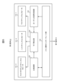
- FIG. 3 is a schematic functional configuration diagram of the first casing 10, which is the main casing.
- FIG. 4 is a schematic functional configuration diagram of the second casing 11, which is a sub-casing.
- FIG. 5 is a schematic functional configuration diagram of the third casing 12, which is a sub-casing.
- FIG. 6 is a flow diagram for explaining the operation mode setting process of the sound bar device 1.
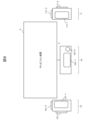
- FIG. 7 is a diagram for explaining an installation example of the sound bar device 1 in the default playback mode.
- FIG. 8 is a diagram for explaining an installation example of the sound bar device 1 in the channel change playback mode.
- FIG. 1 is a schematic configuration diagram of a home theater system including a sound bar device 1 according to the present embodiment.
- the home theater system includes a sound bar device 1, a controller 2 for remotely controlling the sound bar device 1, and a television device 3 using an LCD, organic EL, etc. Prepared and configured.
- the sound bar device 1 and the television device 3 are interconnected through a communication interface such as HDMI (registered trademark: High Definition Multimedia Interface). Further, the sound bar device 1 and the controller 2 are interconnected via an access point 4 connected to a network 5 such as a WAN (Wide Area Network) or a LAN (Local Area Network).
- a communication interface such as HDMI (registered trademark: High Definition Multimedia Interface).
- the sound bar device 1 and the controller 2 are interconnected via an access point 4 connected to a network 5 such as a WAN (Wide Area Network) or a LAN (Local Area Network).
- a network 5 such as a WAN (Wide Area Network) or a LAN (Local Area Network).
- 2(A) to 2(D) are a schematic front view, a schematic top view, a schematic left side view, and a schematic right side view of the sound bar device 1.
- the sound bar device 1 includes a first housing 10 as a main housing, and a second housing 11 and a third housing 12 as sub housings.
- the first casing 10 and the second casing 11 are provided with an attachment/detachment mechanism 13-1 for detachably attaching the second casing 11 to the left side of the first casing 10.
- This attachment/detachment mechanism 13-1 has two features, such as providing a convex portion on either the left side surface of the first housing 10 or the right side surface of the second housing 11, and providing a concave portion on the other side that fits with the convex portion.
- the two casings 10 and 11 may be connected by a mechanical structure of two parts, or a magnet may be installed on either the left side of the first casing 10 or the right side of the second casing 11.
- the two casings 10 and 11 may be connected using a physical force acting between the two members, such as by installing a metal plate on the other side that is attracted to the magnet.
- first casing 10 and the third casing 12 are provided with an attachment/detachment mechanism 13-2 for detachably attaching the third casing 12 to the right side of the first casing 10. Similar to the attachment/detachment mechanism 13-1, this attachment/detachment mechanism 13-2 has a convex portion installed on either the right side of the first housing 10 or the left side of the third housing 12, and the convex portion on the other side.
- the two casings 10 and 12 may be connected by a mechanical structure of the two parts, such as by installing a fitting recess, or the right side of the first casing 10 and the third casing 12 may be connected.
- the two casings 10 and 12 are connected using physical force acting between the two members, such as by installing a magnet on one side of the left side and installing a metal plate that is attracted to the magnet on the other side. It can be anything.
- the first housing 10 has a center channel speaker 101-1 and a subwoofer channel speaker 101-2 on the front
- the second housing 11 has a left channel speaker 111-1 on the front, top, and left side, respectively.
- a height channel speaker 111-2 and a left surround channel speaker 111-3 are arranged
- the third housing 12 has a right channel speaker 121-1, a height channel speaker 121-2, and a right channel speaker 121-2 on the front, top, and right sides, respectively.
- a light surround channel speaker 121-3 is arranged.
- the left surround channel speaker 111-3 is installed on the left side of the second housing 11 so as to emit sound to the left front
- the right surround channel speaker 121-3 is installed to emit sound to the right front.
- the height channel speakers 111-2 and 121-2 are installed on the right side of the third housing 12, and the height channel speakers 111-2 and 121-2 are installed on the second housing 11 and the third housing 12, respectively, so as to emit sound upward and forward. is installed on the top of the.
- FIG. 3 is a schematic functional configuration diagram of the first casing 10, which is the main casing.
- the first housing 10 which is the main housing, has a television device interface section 102, a sub-housing interface section 103, as well as the above-mentioned center channel speaker 101-1 and subwoofer channel speaker 101-2. , a wireless LAN interface section 104, a main playback section 105, an audio signal transmission section 106, and a main control section 107.
- the television device interface section 102 is a communication interface for connecting to the television device 3 via HDMI (registered trademark).
- the sub-casing interface unit 103 is a communication interface for connecting to the second casing 11 and the third casing 12, which are sub-casings, by short-range wireless communication such as Bluetooth (registered trademark).
- the wireless LAN interface unit 104 is a communication interface for connecting to the access point 4 via wireless LAN.
- the main playback unit 105 extracts and plays back the audio signal of the channel assigned to the speaker it accommodates from the multi-channel audio signal received from the television device 3 via the television device interface unit 102, and reproduces it. Output from the speaker housed in.
- center channel and subwoofer channel audio signals are extracted from a multichannel audio signal, reproduced, and output from center channel speaker 101-1 and subwoofer channel speaker 101-2, respectively.
- the audio signal transmission unit 106 transmits, for each sub-casing, the audio of the channel assigned to the speaker accommodated in the sub-casing from the multi-channel audio signal received from the television device 3 via the television device interface unit 102.
- the signal is extracted and transmitted from the sub-casing interface section 103 to this sub-casing.
- the audio signal transmitter 106 reproduces the left channel and left surround from the multi-channel audio signal.
- the multi-channel audio signals including these audio signals are extracted to the second housing 11, and the right channel, right surround channel, and height channel are extracted from the multi-channel audio signals. Audio signals are extracted, and a multichannel audio signal including these audio signals is transmitted to the third housing 12.
- the audio signal transmitter 106 transmits the light channel, right surround channel, and light surround channel from the multichannel audio signal.
- the height channel audio signal is extracted and the multichannel audio signal including these audio signals is sent to the second housing 11, and the left channel, left surround channel, and height channel audio signals are extracted from the multichannel audio signal.
- a multichannel audio signal including these audio signals is transmitted to the third housing 12.
- the main control unit 107 collectively controls each unit 101-1, 101-2, 102 to 106 of the first casing 10, which is the main casing.
- the main control unit 107 when the main control unit 107 receives a channel change instruction from the controller 2 via the wireless LAN interface unit 104, the main control unit 107 changes the channel of the second case 11 and the third case 12, which are sub cases, from the default playback mode. Shift to playback mode.
- the channels assigned to the left channel speaker 111-1, height channel speaker 111-2, and left surround channel speaker 111-3 housed in the second housing 11 are designated as a right channel and a right surround channel, respectively. , and the height channel, and transmits a channel change notification to the second housing 11 via the sub-casing interface unit 103.
- the channels assigned to the right channel speaker 121-1, height channel speaker 121-2, and right surround channel speaker 121-3 housed in the third housing 12 are set as a left channel, a left surround channel, and a height channel, respectively.
- a channel change notification is sent to the third housing 12 via the sub-casing interface unit 103.
- the main control unit 107 when the main control unit 107 receives a channel recovery instruction from the controller 2 via the wireless LAN interface unit 104, the main control unit 107 changes the second housing 11 and the third housing 12, which are sub-casings, from the channel change playback mode to the default. Shift to playback mode.
- the channels assigned to the left channel speaker 111-1, height channel speaker 111-2, and left surround channel speaker 111-3 housed in the second housing 11 are respectively assigned as a left channel, a height channel, and a height channel. and restores to the left surround channel, and transmits a channel restoration notification to the second housing 11 via the sub-casing interface unit 103.
- the channels assigned to the right channel speaker 121-1, height channel speaker 121-2, and right surround channel speaker 121-3 housed in the third housing 12 are set as a right channel, a height channel, and a ride surround channel, respectively.
- a channel restoration notification is sent to the third case 12 via the sub-case interface section 103.
- the second housing 11 and the third housing 12, which are sub-casings, are set to the default playback mode, and the main control unit 107
- a left channel, a height channel, and a left surround channel are respectively assigned to the left channel speaker 111-1, height channel speaker 111-2, and left surround channel speaker 111-3 housed in the second housing 11, and the third housing
- a right channel, a height channel, and a ride surround channel are respectively assigned to a right channel speaker 121-1, a height channel speaker 121-2, and a right surround channel speaker 121-3 housed in the speaker 12.
- the functional configuration of the first housing 10, which is the main housing shown in FIG. 3, includes integrated logic such as ASIC (Application Specific Integrated Circuit) and FPGA (Field Programmable Gate Array). It may be realized in hardware by IC. Alternatively, it may be realized in software by a computer such as a DSP (Digital Signal Processor).
- ASIC Application Specific Integrated Circuit
- FPGA Field Programmable Gate Array
- FIG. 4 is a schematic functional configuration diagram of the second casing 11, which is a sub-casing.
- the second housing 11 which is a sub housing, includes the above-mentioned left channel speaker 111-1, height channel speaker 111-2, and left surround channel speaker 111-3, as well as a main housing interface section 112. , an audio signal receiving section 113 , a sub-playback section 114 , and a main control section 115 .
- the main housing interface unit 112 is a communication interface for connecting to the first housing 10, which is the main housing, by short-range wireless communication such as Bluetooth (registered trademark).
- the audio signal receiving unit 113 is assigned to the speakers 111-1 to 111-3 housed in the second housing 11 from the first housing 10, which is the main housing, via the main housing interface unit 112. receiving a multi-channel audio signal including audio signals of channels;
- the sub-reproduction unit 114 reproduces the multi-channel audio signal received by the audio signal receiving unit 113 from the first housing 10, which is the main housing, for each channel, and transmits the reproduced audio signal of each channel to the corresponding speaker 111-. Output from 1 to 111-3.
- the multi-channel audio signal received from the first housing 10 is played back for each left channel, height channel, and left surround channel, and the played left channel audio signal, height channel audio signal, and left surround channel audio signals are output from left channel speaker 111-1, height channel speaker 111-2, and left surround channel speaker 111-3, respectively.
- the multi-channel audio signal received from the first housing 10 is played back for each light channel, right surround channel, and height channel, and the played light channel audio signal, right surround channel audio signal, and Height channel audio signals are output from left channel speaker 111-1, height channel speaker 111-2, and left surround channel speaker 111-3, respectively.
- the main control unit 115 centrally controls each unit 111-1, 111-2, 111-3, and 112 to 114 of the second casing 11, which is a sub-casing.
- the main control unit 115 when the main control unit 115 receives a channel change notification from the first housing 10 which is the main housing via the main housing interface unit 112, the main control unit 115 changes the playback mode of the sub playback unit 114 from the default playback mode to the channel change playback. When the mode is changed and a channel recovery notification is received, the playback mode of the sub playback section 114 is returned from the channel change playback mode to the default playback mode.
- the functional configuration of the second casing 11, which is a sub-casing shown in FIG. 4, is similar to the functional configuration of the first casing 10, which is the main casing shown in FIG. It may be realized by a computer, or it may be realized by software using a computer such as a DSP.
- FIG. 5 is a schematic functional configuration diagram of the third casing 12, which is a sub-casing.
- the third housing 12 which is a sub housing, includes the above-mentioned light channel speaker 121-1, height channel speaker 122-2, and light surround channel speaker 121-3, as well as the main housing interface section 122. , an audio signal receiving section 123 , a sub-playback section 124 , and a main control section 125 .
- the main housing interface unit 122 is a communication interface for connecting to the first housing 10, which is the main housing, by short-range wireless communication such as Bluetooth (registered trademark).
- the audio signal receiving unit 123 is assigned to the speakers 121-1 to 121-3 housed in the third housing 12 from the first housing 10, which is the main housing, via the main housing interface unit 122. receiving a multi-channel audio signal including audio signals of channels;
- the sub reproduction unit 124 reproduces the multi-channel audio signal received by the audio signal reception unit 123 from the first housing 10, which is the main housing, for each channel, and transmits the reproduced audio signal of each channel to the corresponding speaker 121-. Output from 1 to 121-3.
- the multi-channel audio signal received from the first housing 10 is played back for each light channel, height channel, and right surround channel, and the played light channel audio signal, height channel audio signal, and light surround channel audio signals are output from right channel speaker 121-1, height channel speaker 121-2, and right surround channel speaker 121-3, respectively.
- the multi-channel audio signal received from the first housing 10 is played back for each left channel, left surround channel, and height channel, and the played left channel audio signal, left surround channel audio signal, and Height channel audio signals are output from right channel speaker 121-1, height channel speaker 121-2, and right surround channel speaker 121-3, respectively.
- the main control unit 125 centrally controls each unit 121-1, 121-2, 121-3, and 122 to 124 of the third casing 12, which is a sub-casing.
- the main control unit 125 when the main control unit 125 receives a channel change notification from the first case 10 which is the main case via the main case interface unit 122, the main control unit 125 changes the playback mode of the sub playback unit 124 from the default playback mode to the channel change playback. When the mode is changed and a channel recovery notification is received, the playback mode of the sub playback unit 124 is returned from the channel change playback mode to the default playback mode.
- an integrated logic IC such as an ASIC or FPGA
- a computer such as a DSP.
- FIG. 6 is a flow diagram for explaining the operation mode setting process of the sound bar device 1.
- the main control unit 107 when the main control unit 107 receives a channel change instruction from the controller 2 via the wireless LAN interface unit 104 (YES in S100), the main control unit 107 receives the channel change instruction from the controller 2 via the wireless LAN interface unit 104 (YES in S100).
- the channels assigned to the left channel speaker 111-1, height channel speaker 111-2, and left surround channel speaker 111-3 are changed to a right channel, a right surround channel, and a height channel, respectively (S101).
- the channels assigned to the right channel speaker 121-1, height channel speaker 121-2, and right surround channel speaker 121-3 housed in the third housing 12 are set as a left channel, a left surround channel, and a height channel, respectively. channel (S102).
- the main control unit 107 transmits a channel change notification to the second housing 11 and the third housing 12, which are the sub-casings, via the sub-casing interface unit 103 (S103).
- the main control unit 115 when the main control unit 115 receives a channel change notification from the first case 10 which is the main case via the main case interface unit 112, the main control unit 115 performs sub playback.
- the playback mode of section 114 is shifted from the default playback mode to the channel change playback mode.
- the main control unit 125 when the main control unit 125 receives a channel change notification from the first case 10 which is the main case via the main case interface unit 122, the sub case
- the playback mode of the unit 124 is shifted from the default playback mode to the channel change playback mode (S104).
- the main control unit 107 when the main control unit 107 receives a channel recovery instruction from the controller 2 via the wireless LAN interface unit 104 (YES in S105), the main control unit 107 stores the channel recovery instruction in the second case 11.
- the channels assigned to the left channel speaker 111-1, height channel speaker 111-2, and left surround channel speaker 111-3 are restored to the left channel, height channel, and left surround channel, respectively (S106).
- the channels assigned to the right channel speaker 121-1, height channel speaker 121-2, and right surround channel speaker 121-3 housed in the third housing 12 are designated as a right channel, a height channel, and a right surround channel, respectively.
- channel (S107) transmits a channel recovery notification to the second housing 11 and the third housing 12, which are the sub-casings, via the sub-casing interface unit 103 (S108).
- the main control unit 115 when the main control unit 115 receives a channel recovery notification from the first case 10 which is the main case via the main case interface unit 112, the main control unit 115 performs sub playback.
- the playback mode of section 114 is shifted from the channel change playback mode to the default playback mode.
- the main control unit 125 when the main control unit 125 receives a channel recovery notification from the first case 10 which is the main case via the main case interface unit 122, the main control unit 125 performs sub playback.
- the playback mode of the section 124 is shifted from the channel change playback mode to the default playback mode (S109).
- FIG. 7 is a diagram for explaining an installation example of the sound bar device 1 in the default playback mode.
- the width of the sound bar device 1 becomes smaller than the screen width of the television device 3 due to, for example, replacing the television device 3 with a larger one
- the second casing 11 and the third casing 12 are separated from the first casing 10
- the second casing 11 is moved to the left end of the television device 3
- the third casing 11 is moved to the left end of the television device 3. 12 to the right end of the television device 3.
- the left channel speaker 111-1 is arranged to emit sound from the lower left end of the television device 3 toward the front
- the height channel speaker 111-2 is arranged to emit sound from the lower left end of the television device 3 to the upper front.
- the left surround channel speaker 111-3 is arranged so as to emit sound from the lower left end of the television device 3 toward the front left. Further, the light channel speaker 121-1 is arranged to emit sound from the lower right end of the television device 3 toward the front, and the height channel speaker 121-2 is arranged to emit sound from the lower right end of the television device 3 toward the upper front. The right surround channel speaker 121-3 is arranged so as to emit sound from the lower right end of the television device 3 toward the front right.
- the left channel audio signal is transmitted to the television device 3 by the left channel speaker 111-1.
- the left surround channel audio signal is emitted from the lower left end of the television device 3 toward the front by the left surround channel speaker 111-3
- the right channel audio signal is emitted from the lower left end of the television device 3 toward the front.
- the light channel speaker 121-1 emits sound from the lower right end of the television device 3 toward the front, and the light surround channel audio signal is emitted from the lower right end of the television device 3 toward the front right by the right surround channel speaker 121-3.
- the height channel audio signal is emitted upward and forward from the lower left and right ends of the television device 3 by the height channel speakers 111-2 and 121-2.
- the center channel speaker 101-1 and the subwoofer channel speaker 101-2 are arranged at the front of the first housing 10 located at the lower center of the television device 3, the audio signals of the center channel and subwoofer channel are is emitted from the lower center of the television device 3 toward the front by the center channel speaker 101-1 and the subwoofer channel speaker 101-2. Thereby, an optimal surround environment according to the screen width of the television device 3 can be realized.
- FIG. 8 is a diagram for explaining an installation example of the sound bar device 1 in the channel change playback mode.
- the second housing 11 and the third housing 12 are separated from the first housing 10, the second housing 11 is moved to the right end of the television device 3, and the height channel speaker 111-2 is located on the right side.
- the left channel speaker 111-1 is arranged to emit sound from the right end of the television device 3 toward the front
- the height channel speaker 111-2 is arranged to emit sound from the right end of the television device 3 toward the right front.
- the left surround channel speaker 111-3 is arranged so as to emit sound from the right end of the television device 3 toward the upper front.
- the light channel speaker 121-1 is arranged to emit sound from the left end of the television device 3 toward the front
- the height channel speaker 121-2 is arranged to emit sound from the left end of the television device 3 toward the front left.
- the light surround channel speaker 121-3 is arranged so as to emit sound upwardly and forwardly from the left end of the television device 3.
- the left channel audio signal is transmitted to the television device by the right channel speaker 121-1.
- the left surround channel audio signal is emitted from the left end of the television device 3 toward the front left by the height channel speaker 121-2, and the right channel audio signal is emitted from the left channel speaker 121-2 toward the left front.
- the speaker 111-1 emits sound from the right end of the television device 3 toward the front, and the light surround channel audio signal is emitted from the right end of the television device 3 toward the right front by the height channel speaker 111-2.
- the height channel audio signal is emitted from the left and right ends of the television device 3 upward and forward by the right surround channel speaker 121-3 and the left surround channel speaker 111-3.
- the center channel speaker 101-1 and the subwoofer channel speaker 101-2 are arranged at the front of the first housing 10 located at the lower center of the television device 3, the center channel audio signal and the subwoofer channel audio The signal is emitted from the lower center of the television device 3 toward the front by the center channel speaker 101-1 and the subwoofer channel speaker 101-2. Thereby, an optimal surround environment according to the screen width of the television device 3 can be realized.
- the second housing 11 housing the left channel speaker 111-1 and the third housing 12 housing the right channel speaker 121-1 house the center channel speaker 101-1, respectively. Since it is removable from the first casing 10, when the width of the sound bar device 1 is narrower than the screen width of the television device 3, the second casing 11 and the third casing 12 can be removed from the first casing 10. By separating and arranging these first to third casings 10 to 12 according to the screen width of the television device 3, it is possible to realize an optimal surround environment according to the screen width of the television device 3. can.
- the second housing 11 houses the height channel speaker 111-2 on the top surface and the left surround speaker 111-3 on the left side
- the third housing 12 houses the height channel speaker 111-2 on the top surface. It houses a channel speaker 121-2 and a left surround speaker 121-3 on the right side.
- the first housing 10 which is the main housing, plays the Extracts the left channel, right channel, height channel, left surround channel, and right surround channel audio signals from the channel audio signal, and extracts the multichannel audio signal containing the left channel, height channel, and left surround channel audio signals.
- a multichannel audio signal including audio signals of a right channel, a height channel, and a right surround channel is transmitted to the third housing 12.
- the second housing 11 extracts and reproduces the left channel, height channel, and left surround channel audio signals from the multichannel audio signal received from the first housing 10, and outputs the audio signals to the left channel speaker 111-1.
- the third housing 12 outputs the right channel, height channel, and right surround from the multichannel audio signal received from the first housing 10.
- the channel audio signals are extracted and reproduced, and output from the right channel speaker 121-1, height channel speaker 121-2, and right surround channel speaker 121-3, respectively.
- the first housing 10 which is the main housing
- a multichannel audio signal including left channel, height channel, and left surround channel audio signals is transmitted to the third housing 12.
- the second housing 11 extracts and reproduces the right channel, right surround channel, and height channel audio signals from the multi-channel audio signal received from the first housing 10, and outputs them to the left channel speaker 111-1.
- the third housing 12 outputs the left channel, left surround channel, and height channel from the multichannel audio signal received from the first housing 10.
- the audio signals of the channels are extracted and reproduced, and outputted from the right channel speaker 121-1, height channel speaker 121-2, and right surround channel speaker 121-3, respectively.
- the second housing 11 and the third housing 12 are arranged separately from the first housing 10, in both the installation examples shown in FIGS. 7 and 8, It becomes possible to emit audio signals of each channel from the correct position, and the degree of freedom in installing the first to third casings 10 to 12 increases, improving convenience.
- the first casing 10 is the main casing, and the second casing 11 and the third casing 12 are sub-casings.
- the first casing 10 may be used as a sub-casing, and either the second casing 11 or the third casing 12 may be used as the main casing.
- the first housing 10, which is a sub housing includes a subwoofer channel speaker 101-2 shown in FIG. , and main control section 107, main case interface sections 112, 122, audio signal reception sections 113, 123, sub playback sections 114, 124, and main control sections 115, 125 shown in FIG. 4 or 5 are provided. .
- the second housing 11 or the third housing 12 which is the main housing, includes main housing interface sections 112 and 122, audio signal receiving sections 113 and 123, and sub-playback section 114 shown in FIG. 4 or FIG. 124 and the main control sections 115 and 125, a sub-casing interface section 103, a wireless LAN interface section 104, a main playback section 105, an audio signal transmission section 106, and a main control section 107 shown in FIG. 3 are provided.
- the subwoofer channel speaker 101-2 may be omitted from the first housing 10. Further, at least one of the height channel speaker 111-2 and the left surround channel speaker 111-3 may be omitted from the second housing 11. Similarly, at least one of the height channel speaker 121-2 and the light surround channel speaker 121-3 may be omitted from the third housing 12.
- Bluetooth registered trademark
- the present invention is not limited thereto.
- short-range wireless communication such as Bluetooth (registered trademark) is used for communication between the first housing 10 and the second housing 11.
- wired communication such as HDMI (registered trademark) may be used.
- the first casing 10 and the second casing 11 are provided with connection terminals that are connected by wire when they are connected by the attachment/detachment mechanism 13-1, and these connection terminals provide a wired connection between the two.
- wired communication is used for communication between the two, and when there is no wired connection, short-range wireless communication is used.
- short-range wireless communication such as Bluetooth (registered trademark) is used for communication between the first housing 10 and the third housing 12.
- wired communication such as HDMI (registered trademark) may be used.
- the first casing 10 and the third casing 12 are provided with connection terminals that are connected by wire when they are connected by the attachment/detachment mechanism 13-2, and these connection terminals establish a wired connection between the two.
- wired communication is used for communication between the two, and when there is no wired connection, short-range wireless communication is used.
- communication between the sound bar device 1 and the controller 2 is performed via the access point 4, but the present invention is not limited to this.
- Communication between the sound bar device 1 and the controller 2 may be performed by short-range wireless communication such as Bluetooth (registered trademark).
- the case where the sound bar device 1 is combined with the television device 3 has been described as an example.
- the present invention is not limited thereto.
- the present invention can be widely applied when the sound bar device 1 is used in combination with audio/visual equipment.
Landscapes
- Engineering & Computer Science (AREA)
- Physics & Mathematics (AREA)
- Acoustics & Sound (AREA)
- Signal Processing (AREA)
- Theoretical Computer Science (AREA)
- Multimedia (AREA)
- Health & Medical Sciences (AREA)
- General Health & Medical Sciences (AREA)
- Audiology, Speech & Language Pathology (AREA)
- General Engineering & Computer Science (AREA)
- General Physics & Mathematics (AREA)
- Human Computer Interaction (AREA)
- Otolaryngology (AREA)
- Stereophonic System (AREA)
- Obtaining Desirable Characteristics In Audible-Bandwidth Transducers (AREA)
Abstract
Description
複数のスピーカを有するサウンドバー装置であって、
前面に、センターチャンネルが割り当てられた前記スピーカを有する第1筐体と、
前面に、レフトチャンネルが割り当てられた前記スピーカを有し、前記第1筐体の左側に着脱可能な第2筐体と、
前面に、ライトチャンネルが割り当てられた前記スピーカを有し、前記第1筐体の右側に着脱可能な第3筐体と、を備え、
前記第1筐体、前記第2筐体、および前記第3筐体のうちの1つはメイン筐体であり、残りの2つはサブ筐体であり、
前記メイン筐体は、
マルチチャンネルオーディオ信号を送信する外部機器に接続するための外部機器接続手段と、
前記外部機器より受信したマルチチャンネルオーディオ信号から、自身が有する前記スピーカに割り当てられたチャンネルのオーディオ信号を抽出し再生して、当該スピーカから出力するメイン再生手段と、
前記サブ筐体毎に、前記外部機器より受信したマルチチャンネルオーディオ信号から、当該サブ筐体が有する前記スピーカに割り当てられたチャンネルのオーディオ信号を抽出し送信するオーディオ信号送信手段と、を有し、
前記サブ筐体は、
前記メイン筐体からオーディオ信号を受信するオーディオ信号受信手段と、
前記メイン筐体より受信したオーディオ信号を再生して、自身が有する前記スピーカから出力するサブ再生手段と、を有する。
4:アクセスポイント 5:ネットワーク
10:第1筐体 11:第2筐体 12:第3筐体
13-1、13-2:着脱機構
101-1:センターチャンネルスピーカ
101-2:サブウーファチャンネルスピーカ
111-1:レフトチャンネルスピーカ
111-2、121-2:ハイトチャンネルスピーカ
111-3:レフトサラウンドチャンネルスピーカ
121-1:ライトチャンネルスピーカ
121-3:ライトサラウンドチャンネルスピーカ
102:テレビジョン装置インターフェース部
103:サブ筐体インターフェース部
104:無線LANインターフェース部 105:メイン再生部
106:オーディオ信号送信部 107、115、125:主制御部
112、122:メイン筐体インターフェース部
113、123:オーディオ信号受信部
114、124:サブ再生部
Claims (5)
- 複数のスピーカを有するサウンドバー装置であって、
前面に、センターチャンネルが割り当てられた前記スピーカを有する第1筐体と、
前面に、レフトチャンネルが割り当てられた前記スピーカを有し、前記第1筐体の左側に着脱可能な第2筐体と、
前面に、ライトチャンネルが割り当てられた前記スピーカを有し、前記第1筐体の右側に着脱可能な第3筐体と、を備え、
前記第1筐体、前記第2筐体、および前記第3筐体のうちの1つはメイン筐体であり、残りの2つはサブ筐体であり、
前記メイン筐体は、
マルチチャンネルオーディオ信号を送信する外部機器に接続するための外部機器接続手段と、
前記外部機器より受信したマルチチャンネルオーディオ信号から、自身が有する前記スピーカに割り当てられたチャンネルのオーディオ信号を抽出し再生して、当該スピーカから出力するメイン再生手段と、
前記サブ筐体毎に、前記外部機器より受信したマルチチャンネルオーディオ信号から、当該サブ筐体が有する前記スピーカに割り当てられたチャンネルのオーディオ信号を抽出し送信するオーディオ信号送信手段と、を有し、
前記サブ筐体は、
前記メイン筐体からオーディオ信号を受信するオーディオ信号受信手段と、
前記メイン筐体より受信したオーディオ信号を再生して、自身が有する前記スピーカから出力するサブ再生手段と、を有する
ことを特徴とするサウンドバー装置。 - 請求項1に記載のサウンドバー装置であって、
前記第2筐体および前記第3筐体は、
上面に、ハイトチャンネルが割り当てられた前記スピーカをさらに有しており、
前記メイン筐体は、
チャンネル変更指示を受け付ける変更指示受付手段と、
前記変更指示受付手段により前記チャンネル変更指示を受け付けた場合、前記第2筐体が前面および上面に有する前記スピーカに割り当てられているチャンネルをそれぞれライトチャンネルおよびライトサラウンチャンネルに変更するとともに、前記第3筐体が前面および上面に有する前記スピーカに割り当てられているチャンネルをそれぞれレフトチャンネルおよびレフトサラウンドチャンネルに変更するチャンネル設定手段と、をさらに有する
ことを特徴とするサウンドバー装置。 - 請求項2に記載のサウンドバー装置であって、
前記第2筐体は、
左側面に、レフトサラウンドチャンネルが割り当てられた前記スピーカをさらに有しており、
前記第3筐体は、
右側面に、ライトサラウンドチャンネルが割り当てられた前記スピーカをさらに有しており、
前記チャンネル設定手段は、
前記変更指示受付手段により前記チャンネル変更指示を受け付けた場合、さらに、前記第2筐体が左側面に有する前記スピーカおよび前記第3筐体が右側面に有する前記スピーカに割り当てられているチャンネルをそれぞれハイトチャンネルに変更する
ことを特徴とするサウンドバー装置。 - 複数チャンネルのスピーカを有するサウンドバー装置の設定方法であって、
前記サウンドバー装置は、
前面に、センターチャンネルが割り当てられた前記スピーカを有する第1筐体と、
前面および上面に、それぞれ前記スピーカを有し、前記第1筐体の左側に着脱可能な第2筐体と、
前面および上面に、それぞれ前記スピーカを有し、前記第1筐体の右側に着脱可能な第3筐体と、を備えており、
前記第1筐体の左側に、前記第2筐体が上面を上方に向けて配置され、前記第1筐体の右側に、前記第3筐体が上面を上方に向けて配置された場合、前記第2筐体が前面および上面に有する前記スピーカにそれぞれレフトチャンネルおよびハイトチャンネルを割り当てるとともに、前記第3筐体が前面および上面に有する前記スピーカにそれぞれライトチャンネルおよびハイトチャンネルを割り当て、
前記第1筐体の左側に、前記第3筐体が上面を左に向けて配置され、前記第1筐体の右側に、前記第2筐体が上面を右に向けて配置された場合、前記第2筐体が前面および上面に有する前記スピーカにそれぞれライトチャンネルおよびライトサラウンドチャンネルを割り当てるとともに、前記第3筐体が前面および上面に有する前記スピーカにそれぞれレフトチャンネルおよびレフトサラウンドチャンネルを割り当てる
ことを特徴とするサウンドバー装置の設定方法。 - 請求項4に記載のサウンドバー装置の設定方法であって、
前記第2筐体は、
左側面に前記スピーカをさらに有しており、
前記第3筐体は、
右側面に前記スピーカをさらに有しており、
前記第1筐体の左側に、前記第2筐体が上面を上方に向けて配置され、前記第1筐体の右側に、前記第3筐体が上面を上方に向けて配置された場合、前記第2筐体が左側面に有する前記スピーカにレフトサラウンドチャンネルをさらに割り当てるとともに、前記第3筐体の右側面に収容されている前記スピーカにライトサラウンドチャンネルをさらに割り当て、
前記第1筐体の左側に、前記第3筐体が上面を左に向けて配置され、前記第1筐体の右側に、前記第2筐体が上面を右に向けて配置された場合、前記第2筐体が左側面に有する前記スピーカおよび前記第3筐体が右側面に有する前記スピーカにそれぞれハイトチャンネルを割り当てる
ことを特徴とするサウンドバー装置の設定方法。
Priority Applications (2)
| Application Number | Priority Date | Filing Date | Title |
|---|---|---|---|
| EP22933595.5A EP4503648A4 (en) | 2022-03-24 | 2022-10-11 | SOUNDBAR DEVICE AND SOUNDBAR DEVICE CONFIGURATION METHOD |
| US18/849,902 US20250211902A1 (en) | 2022-03-24 | 2022-10-11 | Soundbar device and method for setting up soundbar device |
Applications Claiming Priority (2)
| Application Number | Priority Date | Filing Date | Title |
|---|---|---|---|
| JP2022049172A JP2023142319A (ja) | 2022-03-24 | 2022-03-24 | サウンドバー装置およびサウンドバー装置の設定方法 |
| JP2022-049172 | 2022-03-24 |
Publications (1)
| Publication Number | Publication Date |
|---|---|
| WO2023181465A1 true WO2023181465A1 (ja) | 2023-09-28 |
Family
ID=88100345
Family Applications (1)
| Application Number | Title | Priority Date | Filing Date |
|---|---|---|---|
| PCT/JP2022/037764 Ceased WO2023181465A1 (ja) | 2022-03-24 | 2022-10-11 | サウンドバー装置およびサウンドバー装置の設定方法 |
Country Status (4)
| Country | Link |
|---|---|
| US (1) | US20250211902A1 (ja) |
| EP (1) | EP4503648A4 (ja) |
| JP (1) | JP2023142319A (ja) |
| WO (1) | WO2023181465A1 (ja) |
Families Citing this family (1)
| Publication number | Priority date | Publication date | Assignee | Title |
|---|---|---|---|---|
| JP2023145274A (ja) * | 2022-03-28 | 2023-10-11 | 株式会社ディーアンドエムホールディングス | サウンドバー装置およびサウンドバー装置の設定方法 |
Citations (2)
| Publication number | Priority date | Publication date | Assignee | Title |
|---|---|---|---|---|
| KR20170014954A (ko) * | 2015-07-31 | 2017-02-08 | 엘지전자 주식회사 | 스피커 시스템 |
| US20170223457A1 (en) * | 2016-02-03 | 2017-08-03 | Lg Electronics Inc. | Main speaker, sub speaker and system including the same |
Family Cites Families (4)
| Publication number | Priority date | Publication date | Assignee | Title |
|---|---|---|---|---|
| TW200942063A (en) * | 2008-03-20 | 2009-10-01 | Weistech Technology Co Ltd | Vertically or horizontally placeable combinative array speaker |
| JP6380060B2 (ja) * | 2014-12-01 | 2018-08-29 | ヤマハ株式会社 | スピーカ装置 |
| TWM539750U (zh) * | 2016-12-15 | 2017-04-11 | Sound Cheers Ltd | 環繞式音箱系統 |
| US10893364B2 (en) * | 2018-01-09 | 2021-01-12 | DGL Group Ltd. | Expandable speaker systems |
-
2022
- 2022-03-24 JP JP2022049172A patent/JP2023142319A/ja active Pending
- 2022-10-11 EP EP22933595.5A patent/EP4503648A4/en active Pending
- 2022-10-11 WO PCT/JP2022/037764 patent/WO2023181465A1/ja not_active Ceased
- 2022-10-11 US US18/849,902 patent/US20250211902A1/en active Pending
Patent Citations (2)
| Publication number | Priority date | Publication date | Assignee | Title |
|---|---|---|---|---|
| KR20170014954A (ko) * | 2015-07-31 | 2017-02-08 | 엘지전자 주식회사 | 스피커 시스템 |
| US20170223457A1 (en) * | 2016-02-03 | 2017-08-03 | Lg Electronics Inc. | Main speaker, sub speaker and system including the same |
Non-Patent Citations (1)
| Title |
|---|
| See also references of EP4503648A4 * |
Also Published As
| Publication number | Publication date |
|---|---|
| JP2023142319A (ja) | 2023-10-05 |
| EP4503648A4 (en) | 2026-04-15 |
| EP4503648A1 (en) | 2025-02-05 |
| US20250211902A1 (en) | 2025-06-26 |
Similar Documents
| Publication | Publication Date | Title |
|---|---|---|
| US7986793B2 (en) | Automatically reconfigurable stereo speaker system | |
| CN108605194B (zh) | 沉浸式音频多声道放大器的分布式放大和控制系统 | |
| CN102970633A (zh) | 设备控制装置、设备控制方法和程序 | |
| JP2011515733A (ja) | 積層可能な通信システム | |
| WO2010102249A9 (en) | Modular multimedia management and distribution system | |
| WO2023181465A1 (ja) | サウンドバー装置およびサウンドバー装置の設定方法 | |
| JP7482446B2 (ja) | インターホン子機及び通信システム | |
| JP2013051533A (ja) | 機器制御装置、機器制御方法およびプログラム | |
| KR20150111624A (ko) | 디스플레이장치 및 그 제어방법과, 디스플레이 시스템 | |
| US20080239164A1 (en) | EZ home cinema | |
| US20060217065A1 (en) | Radio frequency remote control apparatus and methodology | |
| CN102946556A (zh) | 一种显示设备以及包括该显示设备的家庭网络系统 | |
| US20160048226A1 (en) | Patient-actuated control device for controlling an audio-visual display and ancillary functions in a hospital room | |
| CN103188534A (zh) | 显示装置、可连接的外部外围设备和显示图像的方法 | |
| KR101292559B1 (ko) | 영상처리장치, 업그레이드장치, 이를 포함하는 디스플레이 시스템 및 그 제어방법 | |
| KR102728733B1 (ko) | 확장이 용이하며 다양한 종류의 장치를 제어하는 통합 제어 장치 | |
| US20170075115A9 (en) | Micro display appatatus | |
| WO2023188474A1 (ja) | サウンドバー装置およびサウンドバー装置の設定方法 | |
| JPH1188800A (ja) | デジタル画像再生システム及び頭部装着型画像表示装置 | |
| JP6399421B2 (ja) | インターホン装置およびインターホンシステム | |
| US20250113134A1 (en) | Bidirectional multi-channel audio link for transducers | |
| JPWO2009144788A1 (ja) | 音声出力機能を備えた映像表示装置、該映像表示装置で行う音量制御方法 | |
| KR200362434Y1 (ko) | 매립형 고화질 영상 유니트 | |
| JPH0737439Y2 (ja) | 複合オ−ディオ装置 | |
| KR20100128201A (ko) | 일체형 강당 통합 제어 시스템 |
Legal Events
| Date | Code | Title | Description |
|---|---|---|---|
| 121 | Ep: the epo has been informed by wipo that ep was designated in this application |
Ref document number: 22933595 Country of ref document: EP Kind code of ref document: A1 |
|
| WWE | Wipo information: entry into national phase |
Ref document number: 18849902 Country of ref document: US |
|
| WWE | Wipo information: entry into national phase |
Ref document number: 2022933595 Country of ref document: EP |
|
| NENP | Non-entry into the national phase |
Ref country code: DE |
|
| ENP | Entry into the national phase |
Ref document number: 2022933595 Country of ref document: EP Effective date: 20241024 |
|
| WWP | Wipo information: published in national office |
Ref document number: 18849902 Country of ref document: US |