WO2023181742A1 - 磁性基板の製造方法 - Google Patents
磁性基板の製造方法 Download PDFInfo
- Publication number
- WO2023181742A1 WO2023181742A1 PCT/JP2023/005791 JP2023005791W WO2023181742A1 WO 2023181742 A1 WO2023181742 A1 WO 2023181742A1 JP 2023005791 W JP2023005791 W JP 2023005791W WO 2023181742 A1 WO2023181742 A1 WO 2023181742A1
- Authority
- WO
- WIPO (PCT)
- Prior art keywords
- resin composition
- resin
- manufacturing
- resin sheet
- magnetic
- Prior art date
- Legal status (The legal status is an assumption and is not a legal conclusion. Google has not performed a legal analysis and makes no representation as to the accuracy of the status listed.)
- Ceased
Links
Images



Classifications
-
- H—ELECTRICITY
- H05—ELECTRIC TECHNIQUES NOT OTHERWISE PROVIDED FOR
- H05K—PRINTED CIRCUITS; CASINGS OR CONSTRUCTIONAL DETAILS OF ELECTRIC APPARATUS; MANUFACTURE OF ASSEMBLAGES OF ELECTRICAL COMPONENTS
- H05K3/00—Apparatus or processes for manufacturing printed circuits
- H05K3/0058—Laminating printed circuit boards onto other substrates, e.g. metallic substrates
-
- H—ELECTRICITY
- H01—ELECTRIC ELEMENTS
- H01F—MAGNETS; INDUCTANCES; TRANSFORMERS; SELECTION OF MATERIALS FOR THEIR MAGNETIC PROPERTIES
- H01F17/00—Fixed inductances of the signal type
- H01F17/04—Fixed inductances of the signal type with magnetic core
-
- H—ELECTRICITY
- H01—ELECTRIC ELEMENTS
- H01F—MAGNETS; INDUCTANCES; TRANSFORMERS; SELECTION OF MATERIALS FOR THEIR MAGNETIC PROPERTIES
- H01F41/00—Apparatus or processes specially adapted for manufacturing or assembling magnets, inductances or transformers; Apparatus or processes specially adapted for manufacturing materials characterised by their magnetic properties
- H01F41/02—Apparatus or processes specially adapted for manufacturing or assembling magnets, inductances or transformers; Apparatus or processes specially adapted for manufacturing materials characterised by their magnetic properties for manufacturing cores, coils, or magnets
- H01F41/0206—Manufacturing of magnetic cores by mechanical means
- H01F41/0233—Manufacturing of magnetic circuits made from sheets
-
- H—ELECTRICITY
- H01—ELECTRIC ELEMENTS
- H01F—MAGNETS; INDUCTANCES; TRANSFORMERS; SELECTION OF MATERIALS FOR THEIR MAGNETIC PROPERTIES
- H01F41/00—Apparatus or processes specially adapted for manufacturing or assembling magnets, inductances or transformers; Apparatus or processes specially adapted for manufacturing materials characterised by their magnetic properties
- H01F41/02—Apparatus or processes specially adapted for manufacturing or assembling magnets, inductances or transformers; Apparatus or processes specially adapted for manufacturing materials characterised by their magnetic properties for manufacturing cores, coils, or magnets
- H01F41/04—Apparatus or processes specially adapted for manufacturing or assembling magnets, inductances or transformers; Apparatus or processes specially adapted for manufacturing materials characterised by their magnetic properties for manufacturing cores, coils, or magnets for manufacturing coils
- H01F41/041—Printed circuit coils
- H01F41/046—Printed circuit coils structurally combined with ferromagnetic material
-
- H—ELECTRICITY
- H05—ELECTRIC TECHNIQUES NOT OTHERWISE PROVIDED FOR
- H05K—PRINTED CIRCUITS; CASINGS OR CONSTRUCTIONAL DETAILS OF ELECTRIC APPARATUS; MANUFACTURE OF ASSEMBLAGES OF ELECTRICAL COMPONENTS
- H05K1/00—Printed circuits
- H05K1/02—Details
- H05K1/03—Use of materials for the substrate
- H05K1/0313—Organic insulating material
- H05K1/0353—Organic insulating material consisting of two or more materials, e.g. two or more polymers, polymer + filler, + reinforcement
- H05K1/0373—Organic insulating material consisting of two or more materials, e.g. two or more polymers, polymer + filler, + reinforcement containing additives, e.g. fillers
-
- H—ELECTRICITY
- H05—ELECTRIC TECHNIQUES NOT OTHERWISE PROVIDED FOR
- H05K—PRINTED CIRCUITS; CASINGS OR CONSTRUCTIONAL DETAILS OF ELECTRIC APPARATUS; MANUFACTURE OF ASSEMBLAGES OF ELECTRICAL COMPONENTS
- H05K1/00—Printed circuits
- H05K1/02—Details
- H05K1/11—Printed elements for providing electric connections to or between printed circuits
- H05K1/115—Via connections; Lands around holes or via connections
- H05K1/116—Lands, clearance holes or other lay-out details concerning the surrounding of a via
-
- H—ELECTRICITY
- H05—ELECTRIC TECHNIQUES NOT OTHERWISE PROVIDED FOR
- H05K—PRINTED CIRCUITS; CASINGS OR CONSTRUCTIONAL DETAILS OF ELECTRIC APPARATUS; MANUFACTURE OF ASSEMBLAGES OF ELECTRICAL COMPONENTS
- H05K1/00—Printed circuits
- H05K1/16—Printed circuits incorporating printed electric components, e.g. printed resistors, capacitors or inductors
- H05K1/165—Printed circuits incorporating printed electric components, e.g. printed resistors, capacitors or inductors incorporating printed inductors
-
- H—ELECTRICITY
- H05—ELECTRIC TECHNIQUES NOT OTHERWISE PROVIDED FOR
- H05K—PRINTED CIRCUITS; CASINGS OR CONSTRUCTIONAL DETAILS OF ELECTRIC APPARATUS; MANUFACTURE OF ASSEMBLAGES OF ELECTRICAL COMPONENTS
- H05K2201/00—Indexing scheme relating to printed circuits covered by H05K1/00
- H05K2201/08—Magnetic details
- H05K2201/083—Magnetic materials
- H05K2201/086—Magnetic materials for inductive purposes, e.g. printed inductor with ferrite core
-
- H—ELECTRICITY
- H05—ELECTRIC TECHNIQUES NOT OTHERWISE PROVIDED FOR
- H05K—PRINTED CIRCUITS; CASINGS OR CONSTRUCTIONAL DETAILS OF ELECTRIC APPARATUS; MANUFACTURE OF ASSEMBLAGES OF ELECTRICAL COMPONENTS
- H05K2201/00—Indexing scheme relating to printed circuits covered by H05K1/00
- H05K2201/09—Shape and layout
- H05K2201/09209—Shape and layout details of conductors
- H05K2201/095—Conductive through-holes or vias
- H05K2201/09563—Metal filled via
-
- H—ELECTRICITY
- H05—ELECTRIC TECHNIQUES NOT OTHERWISE PROVIDED FOR
- H05K—PRINTED CIRCUITS; CASINGS OR CONSTRUCTIONAL DETAILS OF ELECTRIC APPARATUS; MANUFACTURE OF ASSEMBLAGES OF ELECTRICAL COMPONENTS
- H05K2201/00—Indexing scheme relating to printed circuits covered by H05K1/00
- H05K2201/09—Shape and layout
- H05K2201/09209—Shape and layout details of conductors
- H05K2201/095—Conductive through-holes or vias
- H05K2201/09581—Applying an insulating coating on the walls of holes
Definitions
- the present invention relates to a method for manufacturing a magnetic substrate.
- One of the circuit boards used in electronic devices is one obtained by filling the through holes of a core board with a resin composition and curing the resin composition (Patent Documents 1, 2, and 3). Further, as a resin composition for filling through holes in a circuit board for inductor components, a resin composition containing magnetic powder has been used (Patent Document 4).
- a circuit board using a resin composition containing magnetic powder as described above includes a core substrate in which through holes are formed, and a cured product of the resin composition filled in the through holes. Since the cured product contains magnetic powder, it can be used as a magnetic material.
- a substrate in which through holes are filled with a material containing magnetic powder may be referred to as a "magnetic substrate".
- the magnetic materials are required to have high magnetic permeability.
- a printing method such as a screen printing method has been adopted as a method for filling through holes with a resin composition containing magnetic powder.
- the present inventors investigated a method that can satisfactorily fill a through hole with the resin composition even if the content of the magnetic powder in the resin composition is increased.
- the present inventor investigated a method of filling through holes with a resin composition using a resin sheet including a support and a resin composition layer formed on the support. .
- a resin composition using a resin sheet unfilled portions or voids are formed, making it difficult to achieve good filling.
- the present inventor attempted to laminate a resin sheet and a core substrate using a vacuum laminator and fill the through holes with a resin composition.
- a vacuum laminator the resin sheet and the core substrate are laminated by applying pressure to the resin sheet using an elastic member in a vacuum environment.
- an elastic member for example, a rubber press method in which pressure is applied with an elastic mold made of rubber, a diaphragm method in which pressure is applied with a membrane made of an elastic material, etc. are commonly used.
- the resin sheet can sufficiently follow the surface shape of the core substrate, so it was expected that the vacuum laminator would be able to laminate layers without gaps.
- the entire through hole cannot be filled with the resin composition, and an unfilled portion without the resin composition may be formed.
- a two-chamber vacuum laminator In a two-chamber vacuum laminator, a resin sheet and a core substrate are laminated in a vacuum environment in the first chamber as described above, and then the resin sheet is pressurized in an atmospheric pressure environment in a second chamber.
- a two-chamber vacuum laminator is intended for fully automatic continuous production, and in the second chamber, a flat flat plate often presses the resin sheet in order to smooth the resin composition layer. It was expected that by further pressurizing the resin composition in the second chamber, the resin composition would further enter the through-holes, thereby suppressing the formation of unfilled portions.
- voids bubbles
- the present inventor attempted to laminate a resin sheet and a core substrate using a vacuum hot press and fill the through holes with a resin composition.
- a resin sheet and a core substrate are heated under high pressure conditions in a vacuum environment for a long time (Japanese Patent No. 6812091).
- vacuum hot press generally does not require a high degree of vacuum, and was expected to reduce the cost of depressurization and achieve lamination.
- vacuum hot pressing was used, voids were found when the cured resin composition formed in the through-hole was observed.
- the through holes can be filled with the resin composition using a vacuum laminator.
- the resin composition usually adheres not only to the inside of the through-hole but also to the main surface of the core substrate.
- the amount of resin composition that adheres to the main surface of the core substrate increases.
- the cured product is removed by polishing after the resin composition is cured.
- a cured product of a resin composition containing magnetic powder has low abrasiveness and imposes a large load on the polishing process. Therefore, if there is a large amount of cured material, much time and energy are required for polishing. Therefore, it is desirable to have a method that allows the through-holes to be filled with the resin composition even when the resin composition layer is thin.
- the present invention has been devised in view of the above-mentioned problems, and is a method for manufacturing a magnetic substrate that can fill the through holes of a core substrate with a resin composition using a resin sheet while suppressing the formation of voids and unfilled areas.
- the purpose is to provide
- the inventors of the present invention have made extensive studies to solve the above problems. As a result, the inventors have found that by a method that includes pressurizing a resin sheet with a rigid plate under specific heating conditions at a specific degree of vacuum, the resin composition can be formed into through-holes while suppressing the formation of voids and unfilled areas. They discovered that it is possible to fill things with things, and completed the present invention. That is, the present invention includes the following.
- the manufacturing method includes: Step (I) of placing a resin sheet on the core substrate in which the through hole is formed; a step (II) of pressing the resin sheet with a rigid plate and filling the through holes with the resin composition;
- Step (I) includes arranging resin sheets on both sides of the core substrate, The method for manufacturing a magnetic substrate according to [1], wherein step (II) includes pressurizing resin sheets placed on both sides of the core substrate with rigid plates.
- step (II) includes pressurizing resin sheets placed on both sides of the core substrate with rigid plates.
- step (II) includes pressurizing resin sheets placed on both sides of the core substrate with rigid plates.
- step (II) includes pressurizing resin sheets placed on both sides of the core substrate with rigid plates.
- the pressurization in step (II) is performed under a pressure condition of 5 kgf/cm 2 or more.
- step (IV) of polishing the cured resin composition after step (III).
- Step (III) includes forming a cured product layer containing a cured product of the resin composition in the through hole;
- [8] The method for producing a magnetic substrate according to any one of [1] to [7], wherein the amount of magnetic powder is 65% by volume or more based on 100% by volume of nonvolatile components of the resin composition. .
- [9] The method for producing a magnetic substrate according to any one of [1] to [8], wherein the resin composition layer of the resin sheet has a thickness of 150 ⁇ m or less.
- the present invention it is possible to provide a method for manufacturing a magnetic substrate in which through-holes in a core substrate can be filled with a resin composition using a resin sheet while suppressing the formation of voids and unfilled portions.
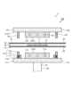
- FIG. 1 is a cross-sectional view schematically showing a laminator used in a manufacturing method according to a first embodiment of the present invention.
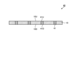
- FIG. 2 is a cross-sectional view schematically showing a magnetic substrate obtained by the manufacturing method according to the first specific example of the present invention.
- FIG. 3 is a cross-sectional view schematically showing a magnetic substrate obtained by the manufacturing method according to the first specific example of the present invention.
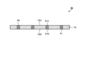
- FIG. 4 is a cross-sectional view schematically showing a magnetic substrate obtained by the manufacturing method according to the first specific example of the present invention.
- FIG. 5 is a cross-sectional view schematically showing a magnetic substrate obtained by the manufacturing method according to the first specific example of the present invention.
- FIG. 1 is a cross-sectional view schematically showing a laminator used in a manufacturing method according to a first embodiment of the present invention.
- FIG. 2 is a cross-sectional view schematically showing a magnetic substrate obtained by the manufacturing method according to the first specific example of the present invention.
- FIG. 6 is a cross-sectional view schematically showing a magnetic substrate obtained by the manufacturing method according to the first specific example of the present invention.
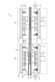
- FIG. 7 is a cross-sectional view schematically showing a laminator used in the manufacturing method according to the second specific example of the present invention.
- a method for manufacturing a magnetic substrate according to an embodiment of the present invention is a method for manufacturing a magnetic substrate using a resin sheet including a support and a resin composition layer formed on the support.
- the resin composition layer contains a resin composition containing magnetic powder, and preferably contains only the resin composition.
- This manufacturing method is Step (I) of placing a resin sheet on the core substrate in which the through hole is formed; a step (II) of pressurizing the resin sheet with a rigid plate and filling the through holes with the resin composition; including.
- step (I) a resin sheet is placed on the core substrate so that the core substrate and the resin composition layer are in contact with each other. Then, in step (II), the resin sheet is pressed by a rigid plate, so that the resin composition contained in the resin composition layer is filled into the first through holes.
- Step (II) of the method for manufacturing a magnetic substrate according to an embodiment of the present invention is to pressurize the resin sheet with the rigid plate so that the rigid plate contacts the resin sheet in an environment having a degree of vacuum within a specific range. including.
- the resin composition can smoothly enter the first through hole. Therefore, the first through hole can be filled with the resin composition without any gaps, so it is possible to suppress the formation of an unfilled portion without the resin composition in the first through hole.
- the generation of voids (bubbles) in the resin composition can be suppressed. Therefore, since the formation of both voids and unfilled portions can be suppressed, excellent filling properties can be achieved. Therefore, it is possible to obtain a magnetic substrate that includes a core substrate and a resin composition that satisfactorily fills the core substrate.
- a method for manufacturing a magnetic substrate according to an embodiment of the present invention usually includes: After step (II), step (III) of curing the resin composition further including.
- step (III) of curing the resin composition further including.
- the resin composition filled in the first through hole is cured, a magnetic substrate including a core substrate and a cured product of the resin composition filling the first through hole of the core substrate can be obtained.
- the present inventor speculates as follows about the mechanism by which the above-mentioned effects can be obtained by the manufacturing method according to the present embodiment.
- the technical scope of the present invention is not limited to the following mechanism.
- the pressure applied to the resin composition may be insufficient, and a sufficient amount of the resin composition may not be able to enter the first through hole.
- the elastic member subjected to the pressure may deform so as to close the opening of the first through hole. If the opening is blocked by the elastic member, no more resin composition can enter the first through hole, and an unfilled portion may be formed in the first through hole.
- the purpose of the second chamber of a two-chamber vacuum laminator is to pressurize the resin sheet with a flat plate to achieve smoothing, and the operator is motivated to prepare a vacuum environment even at the expense of using it. Since there was no such thing, it was not possible to suppress the occurrence of voids.
- the resin sheet is pressurized with a rigid plate in a vacuum environment with a high degree of vacuum. Since the rigid plate does not consume pressure due to elastic deformation, it can apply a sufficiently large pressure to the resin composition, and as a result, a sufficient amount of the resin composition can enter the first through hole. Further, the rigid plate does not block the opening of the first through hole due to deformation. Furthermore, in a vacuum environment with a high degree of vacuum, residual gas is so small that it can be ignored, so it is possible to suppress the gas from remaining in the resin composition and its cured product. Therefore, the formation of voids and unfilled portions can be suppressed, making it possible to achieve excellent filling properties.
- a method for manufacturing a magnetic substrate according to an embodiment of the present invention includes a step (I) of arranging a resin sheet on a core substrate.
- the resin sheet is arranged so that the core substrate and the resin composition layer are in contact with each other.
- the core substrate is a substrate on which a first through hole is formed, and usually includes a support substrate.
- the supporting substrate include insulating substrates such as a glass epoxy substrate, a metal substrate, a polyester substrate, a polyimide substrate, a BT resin substrate, and a thermosetting polyphenylene ether substrate.
- a conductor layer may be provided on the support substrate.
- the conductor layer may be provided on one side or both sides of the support substrate.
- Examples of the conductor layer include a layer made of metal such as copper.
- the conductor layer may be, for example, a copper foil such as a copper foil with a carrier. Further, the conductor layer may be made of the same material as the conductor layer described in step (V) described below. Furthermore, the conductor layer may be formed on the inner peripheral surface of the first through hole.
- the first through hole penetrates the core substrate in the thickness direction. Therefore, the first through hole opens on both main surfaces (ie, the front surface and the back surface) of the core substrate.
- the shape of the opening of the first through hole is not particularly limited, and may be any shape such as rectangular, circular, substantially rectangular, or substantially circular. Further, the dimensions of the opening depend on the design of the magnetic substrate, but for example, when the shape of the opening is rectangular, it is preferably 5 mm x 5 mm or less, more preferably 3 mm x 3 mm or less, or 2 mm x 2 mm or less. Moreover, when the shape of the opening is circular, the diameter is preferably 5 mm or less, more preferably 3 mm or less, or 2 mm or less.
- the lower limit of the dimensions of the opening depends on the design of the magnetic substrate, but in the case of a rectangular opening, it may usually be 0.2 mm x 0.2 mm or more, and in the case of a circular opening, it usually has a diameter of 0. .2 mm or more.
- the opening is usually formed in a region of the circuit board where no circuit wiring is formed.
- the core substrate is formed by forming the first through hole on the core substrate before the first through hole is formed by a processing method such as drilling, laser irradiation, plasma irradiation, etc., and further by plating or other method as necessary. It can be manufactured by forming a conductor layer using a forming method. Further, the core substrate may be purchased and prepared from the market.
- the resin sheet includes a support and a resin composition layer.
- a support a film-like or sheet-like member can usually be used. Further, the resin composition layer is formed on the support.
- the resin composition layer contains a resin composition containing magnetic powder. This resin composition is filled into the first through hole of the core substrate in step (II). Details of the resin sheet will be described later.
- step (I) the resin sheet is usually arranged so that the resin composition layer covers the opening of the first through hole opened in the main surface of the core substrate.
- the resin sheet may be installed on one side of the core substrate or on both sides. From the viewpoint of suppressing warping of the manufactured magnetic substrate, it is preferable to install resin sheets on both sides of the core substrate. Therefore, step (I) preferably includes arranging resin sheets on both sides of the core substrate. Arranging the resin sheet on one side of the core substrate and disposing the resin sheet on the other side of the core substrate may be performed simultaneously or sequentially.
- the thickness of the resin composition layer of the resin sheet placed on one side of the core substrate may be different from the thickness of the resin composition layer of the resin sheet placed on the other side of the core substrate, but It is preferable that they are the same from the viewpoint of easily polishing the cured product.
- the resin sheet When installing the resin sheet on the core substrate, the resin sheet may be placed so as to be partially in contact with the core substrate, or the resin composition layer may be in close contact with the core substrate.
- a method for manufacturing a magnetic substrate according to an embodiment of the present invention includes, after step (I), a step (II) of pressurizing the resin sheet with a rigid plate and filling the first through hole with the resin composition. .
- step (II) of pressurizing the resin sheet with a rigid plate and filling the first through hole with the resin composition.
- the resin sheet is pressurized by the rigid plate, the resin composition contained in the resin composition layer flows and enters the first through hole of the core substrate, filling the first through hole.
- a rigid plate refers to a plate made of a rigid material.
- a material having enough rigidity to fill the first through hole of the core substrate with the resin composition can be used.
- a material that does not deform when pressurized is preferable, and therefore a material that does not deform under the pressurizing conditions and heating conditions in step (II) is preferable, and a metal material is particularly preferable.
- the metal material include iron, aluminum, and alloys thereof.
- the alloy include stainless steel. Among these, stainless steel is preferred because it has excellent rust resistance.
- the rigid plate has a pressure surface that can contact the resin sheet and pressurize the resin sheet.
- This pressurizing surface is usually a smooth plane.
- the pressurizing surface has high rigidity and therefore does not normally undergo deformation even under pressure during pressurization.
- the HV hardness of the pressure surface of the rigid plate is preferably 150 or more, more preferably 200 or more, even more preferably 300 or more, and preferably 1000 or less, more preferably 700 or less.
- HV hardness is also referred to as Vickers hardness, and can be measured according to JIS Z 2244.
- the thickness of the rigid plate is preferably 0.1 mm or more, more preferably 1 mm or more, and preferably 10 mm or less, more preferably 5 mm or less.
- the pressurization of the resin sheet in step (II) is performed so that the rigid plate is in contact with the resin sheet.
- the rigid plate is in contact with the resin sheet means that there is no arbitrary layer such as a rubber film between the rigid plate and the resin sheet.
- the pressurizing surface of the rigid plate comes into contact with the resin sheet, and the pressurizing surface pushes the resin sheet, thereby achieving pressurization.
- the absence of any layer between the rigid plate and the resin sheet allows for greater pressure to be applied to the entire resin sheet. Therefore, not only the resin composition above the opening of the first through hole, but also the resin composition around the opening can be forced into the first through hole under a large pressure, so that the first through hole can be filled smoothly. be able to.
- the pressurization of the resin sheet in step (II) is performed in a specific range of vacuum degree.
- the resin sheet is pressurized in a closed space having a degree of vacuum within a specific range. Therefore, the resin sheet may be pressurized in an environment within the closed space having a degree of vacuum within a specific range.
- the range of the degree of vacuum is usually 1.3 kPa or less, preferably 1.0 kPa or less, more preferably 0.5 kPa or less, particularly preferably 0.2 kPa or less.
- the lower limit is ideally 0 kPa or more, but usually 0.01 kPa or more.
- the pressurization of the resin sheet in step (II) is performed under specific heating conditions.
- the temperature of the resin sheet in contact with the rigid plate is controlled to a specific temperature.
- the temperature range of the heating conditions is usually 80°C or higher, preferably 85°C or higher, more preferably 90°C or higher, and preferably 160°C or lower, more preferably 155°C or lower, particularly preferably 150°C or lower.
- the fluidity of the resin composition contained in the resin composition layer can be increased and the resin composition can be smoothly entered into the first through hole.
- the pressure conditions that the rigid plate applies to the resin sheet in step (II) are not limited as long as the first through holes can be filled with the resin composition.
- the pressure condition is preferably 5 kgf/cm 2 or more, more preferably 7 kgf/cm 2 or more, and particularly preferably 10 kgf/cm 2 or more.
- resin compositions containing magnetic powder tend to have low fluidity, so it is preferable to apply pressure under high pressure conditions as described above.
- the upper limit of the pressure conditions may be, for example, 100 kgf/cm 2 or less, 70 kgf/cm 2 or less, 50 kgf/cm 2 or less, etc.
- the specific pressurization time may vary depending on the composition of the resin composition and the size of the first through hole, but is preferably 10 seconds or more, more preferably 20 seconds or more, particularly preferably 30 seconds or more, Preferably it is 30 minutes or less, more preferably 20 minutes or less, particularly preferably 10 minutes or less.
- step (I) includes placing resin sheets on both sides of the core substrate
- step (II) includes pressurizing at least one of the resin sheets. From the viewpoint of more reliably suppressing the formation of unfilled portions, step (II) preferably includes pressing both resin sheets placed on both sides of the core substrate with rigid plates.
- step (II) the first through hole of the core substrate can be filled with the resin composition. At this time, it is possible to suppress the formation of unfilled portions, which are voids in which there is no resin composition, within the first through hole. Further, it is possible to suppress the formation of voids in the resin composition in the first through hole. Thus, according to step (II), it is possible to fill the first through hole with the resin composition with excellent filling properties.
- a portion of the resin composition contained in the resin composition layer fills the first through hole. Therefore, another part of the resin composition contained in the resin composition layer does not enter the first through hole, so that it can adhere to the main surface of the core substrate and form a layer.
- step (II) the resin sheet support is peeled off. Peeling of the support may be performed before or after step (III), which will be described later.
- the method for manufacturing a magnetic substrate according to an embodiment of the present invention may include a step (III) of curing the resin composition after step (II). By curing the resin composition, a cured product of the resin composition can be formed. Therefore, a magnetic substrate including a cured product of the resin composition can be obtained.
- the resin composition is usually cured by heat curing.
- the thermal curing conditions for the resin composition can be appropriately set within a range that allows curing of the resin composition layer to proceed.
- the curing temperature is preferably 60°C or higher, more preferably 70°C or higher, even more preferably 80°C or higher, and preferably 245°C or lower, more preferably 220°C or lower, and even more preferably 200°C or lower.
- the curing time is preferably 5 minutes or more, more preferably 10 minutes or more, even more preferably 15 minutes or more, and preferably 120 minutes or less, more preferably 110 minutes or less, and still more preferably 100 minutes or less.
- the degree of curing of the cured product obtained in step (III) is preferably 80% or more, more preferably 85% or more, and still more preferably 90% or more.
- the degree of curing can be measured using, for example, a differential scanning calorimeter.
- step (III) usually includes forming a cured material layer within the first through hole.
- the cured material layer formed in the first through hole may be referred to as a "filled cured material layer.”
- the cured product of the resin composition usually forms a cured product layer also on the main surface of the core substrate. Therefore, step (III) usually includes forming a cured material layer on the main surface of the core substrate.
- the cured material layer formed on the main surface of the core substrate is sometimes referred to as an "adhesive cured material layer.”
- the cured material layers such as the filled cured material layer and the adhered cured material layer are layers containing a cured product of the resin composition, and preferably contain only the cured product of the resin composition.
- the thickness of the adhered cured material layer before step (IV) described below may be preferably 100 ⁇ m or less, more preferably 80 ⁇ m or less, particularly preferably 60 ⁇ m or less.
- the method for manufacturing a magnetic substrate according to an embodiment of the present invention may include, after step (III), a step (IV) of polishing a cured product as a cured resin composition.
- a step (IV) of polishing a cured product as a cured resin composition.
- the adhered cured material layer outside the first through hole is a surplus portion that is unnecessary for the product, so it is desirable to remove it. Therefore, in step (IV), it is preferable to polish and remove the adhered cured material layer.
- a part of the cured material layer filled in the first through hole may be polished at the same time as the adhered cured material layer on the main surface of the core substrate, and a part of the core substrate may be polished. It's okay.
- polishing method examples include buff polishing, belt polishing, ceramic polishing, and the like.
- Commercially available buffing devices include, for example, "NT-700IM” manufactured by Ishii Hyoki Co., Ltd.
- a flat polished surface can be formed on the surface of the filled cured material layer.
- the arithmetic mean roughness (Ra) of this polished surface is preferably 100 nm or more, more preferably 150 nm or more, still more preferably 200 nm or more, and preferably from the viewpoint of forming a conductive layer with high adhesion on the polished surface. It is 1000 nm or less, more preferably 900 nm or less, and even more preferably 800 nm or less.
- Surface roughness (Ra) can be measured using, for example, a non-contact surface roughness meter.
- the polished surface of the filled cured material layer formed by polishing is flush with the main surface of the core substrate.
- a certain surface and another surface are “flushed”, it means that these surfaces form a single plane. Therefore, the main surface of the core substrate and the polished surface of the filled cured material layer can form a smooth plane.
- a conductor layer may be formed on this smooth plane in step (VI).
- the method for manufacturing a magnetic substrate according to an embodiment of the present invention may include, after step (III), a step (V) of forming a through hole in the cured material layer filled in the first through hole.
- step (V) is usually performed after step (IV).
- the above-mentioned through hole formed in the filled cured material layer may be hereinafter referred to as "second through hole".
- the second through hole can be formed by a known method using, for example, a drill, laser, plasma, etching medium, etc., taking into consideration the characteristics of the cured product and the dimensions of the first through hole.
- the shape of the opening of the second through hole may be the same as the shape of the opening of the first through hole.
- the opening size of the second through hole is not particularly limited as long as it is smaller than the opening size of the first through hole.
- a method for manufacturing a magnetic substrate according to an embodiment of the present invention may include a step (VI) of forming a conductor layer after step (III).
- step (VI) is usually performed after step (IV).
- step (VI) may be performed after step (V) to form a conductor layer on the wall surface of the second through hole.
- a conductor layer is usually formed on a cured material layer.
- the conductor layer is preferably formed on the filled cured material layer.
- the conductor layer may be formed on the core substrate.
- the conductive layer is formed on the polished surface of the filled cured material layer and the main surface of the core substrate.
- the conductor layer may be formed on one side or both sides of the magnetic substrate. Further, the conductor layer may be formed on the wall surface of the second through hole formed in step (V).
- the conductor layer may be formed of a conductor.
- conductors include single metals such as gold, platinum, palladium, silver, copper, aluminum, cobalt, chromium, zinc, nickel, titanium, tungsten, iron, tin, and indium; gold, platinum, palladium, silver, copper, Examples include alloys of two or more metals selected from the group of aluminum, cobalt, chromium, zinc, nickel, titanium, tungsten, iron, tin, and indium.
- chromium, nickel, titanium, aluminum, zinc, gold, palladium, silver or copper, nickel-chromium alloy, copper-nickel alloy, copper-titanium alloy can be used from the viewpoint of versatility, cost, ease of patterning, etc.
- chromium, nickel, titanium, aluminum, zinc, gold, palladium, silver or copper, or a nickel-chromium alloy is used, and copper is even more preferably used.
- the thickness of the conductor layer is preferably 1 ⁇ m or more, more preferably 3 ⁇ m or more, even more preferably 5 ⁇ m or more, and preferably 70 ⁇ m or less, more preferably 50 ⁇ m or less, still more preferably 40 ⁇ m or less, particularly preferably 30 ⁇ m or less. .
- the conductor layer can be formed, for example, by a formation method such as a plating method, a sputtering method, or a vapor deposition method. Among these, plating is preferred. Alternatively, a part of the formed conductor layer may be removed by a removal process such as etching to obtain a patterned conductor layer having a desired planar shape. Unless otherwise specified, the planar shape refers to the shape viewed from the thickness direction. In a preferred embodiment, a patterned conductor layer having a desired wiring pattern can be formed by plating by an appropriate method such as a semi-additive method or a fully additive method.
- a portion of the conductor layer included in the core substrate may be removed.
- a coil-shaped wiring may be formed by a conductor layer formed on the cured material layer and the core substrate, and a conductor layer included inside the core substrate, and an inductor element may be obtained within the magnetic substrate.
- a plating seed layer is formed on the cured material layer by electroless plating.
- an electrolytic plating layer is formed by electrolytic plating.
- the mask pattern is removed and the unnecessary plating seed layer is further removed by a process such as etching to form a patterned conductor layer having a desired wiring pattern.
- an annealing treatment may be performed if necessary in order to improve the adhesion strength of the patterned conductor layer.
- the annealing treatment can be performed, for example, by heating at 150° C. to 200° C. for 20 minutes to 90 minutes.
- a magnetic substrate including a cured product layer formed of a cured product of a resin composition containing magnetic powder can be obtained.
- the magnetic substrate obtained by the above manufacturing method it is possible to suppress the formation of unfilled portions as voids without cured material and voids as air bubbles in the cured material in the first through hole of the core substrate. can.
- the first through hole can be filled with not only the resin composition above the opening of the first through hole, but also the resin composition surrounding the opening. Therefore, even if a resin sheet having a thin resin composition layer is used, the first through hole can be filled with the resin composition.
- the thickness of the adhered cured material layer formed on the main surface of the core substrate can be made thin. Therefore, the time required to remove the adhered cured material layer by polishing can be shortened. Therefore, it is possible to shorten the manufacturing time of the magnetic substrate.
- an inductor component including the magnetic substrate can be manufactured. For example, by forming a coiled wiring using a conductor layer around at least a portion of the filled cured material layer, an inductor component having an inductor pattern including the wiring can be obtained.
- an inductor component for example, the one described in Japanese Patent Application Laid-Open No. 2016-197624 can be applied.
- the magnetic substrate can be used as a wiring board for mounting electronic components such as semiconductor chips, and can also be used as a (multilayer) printed wiring board using such a wiring board as an inner layer substrate.
- a wiring board can be used as a chip inductor component made into individual pieces, and the chip inductor component can also be used as a surface-mounted printed wiring board.
- various types of semiconductor devices can be manufactured using such a wiring board. Semiconductor devices including such wiring boards can be suitably used in electrical products (e.g., computers, mobile phones, digital cameras, televisions, etc.) and vehicles (e.g., motorcycles, automobiles, trains, ships, aircraft, etc.). .
- the method for manufacturing a magnetic substrate according to an embodiment of the present invention may further include an arbitrary step in combination with the above-described steps.
- the method for manufacturing a magnetic substrate may include a step (VII) of pressing the resin sheet with an elastic member between steps (I) and (II).
- some two-chamber laminators include a first chamber provided with an elastic member capable of pressurizing the resin sheet, and a second chamber provided with a rigid plate capable of pressurizing the resin sheet.
- Examples of such a two-chamber laminator include the rubber press type "CVP-700” manufactured by Nikko Materials, and the diaphragm type laminator "MVLP-500/600IIB” manufactured by Meiki Seisakusho.
- the pressurization in step (II) described above may be performed in the second chamber.
- a step (VII) of pressurizing the resin sheet with an elastic member in the first chamber may be performed before step (II).
- step (VII) the resin sheet is pressed by an elastic member to fill the first through holes of the core substrate with the resin composition contained in the resin composition layer.
- step (II) since pressurization in step (II) is further performed after step (VII), depending on step (VII), the entire first through hole does not necessarily need to be filled with the resin composition.
- a rubber plate or sheet is usually used as the elastic member.
- an elastic member may be provided on the rigid plate, and the resin sheet may be pressed by the elastic member.
- the resin sheet is pressurized in step (VII) so that the elastic member is in contact with the resin sheet.
- the elastic member is in contact with the resin sheet means that there is no arbitrary layer between the elastic member and the resin sheet.
- step (VII) it is preferable that the pressurization of the resin sheet in step (VII) be carried out at a degree of vacuum within the specific range described in step (II).
- the pressurization of the resin sheet in step (VII) be carried out at a degree of vacuum within the specific range described in step (II).
- step (VII) The pressurization of the resin sheet in step (VII) is preferably performed under the specific heating conditions described in step (II). When pressurizing under such heating conditions, the resin composition can enter the first through hole particularly smoothly.
- step (VII) Pressurization of the resin sheet in step (VII) may be performed under the pressure conditions described in step (II). Moreover, the pressurization of the resin sheet in step (VII) may be performed for the time described in step (II). Furthermore, when step (I) includes placing resin sheets on both sides of the core substrate, step (VII) includes pressurizing both resin sheets placed on both sides of the core substrate with an elastic member. You can stay there.
- the method for manufacturing a magnetic substrate according to an embodiment of the present invention includes an optional step of heating the resin composition layer at a temperature lower than the curing temperature between step (II) and step (III). VIII).
- the heating in this step (VIII) may be hereinafter referred to as "preheating".
- preheating For example, prior to curing the resin composition layer in step (III), at a temperature of usually 50°C or higher and lower than 120°C (preferably 60°C or higher and 110°C or lower, more preferably 70°C or higher and 100°C or lower),
- the resin composition layer may be preheated for usually 5 minutes or more (preferably 5 minutes to 150 minutes, more preferably 15 minutes to 120 minutes).
- the cured material layer is added to the cured material layer in order to further increase the degree of curing of the cured material layer.
- the method may also include a step (IX) of performing heat treatment.
- the temperature in the heat treatment can be similar to the curing temperature of the resin composition described above.
- the specific heat treatment temperature is preferably 120°C or higher, more preferably 130°C or higher, even more preferably 150°C or higher, and preferably 245°C or lower, more preferably 220°C or lower, and still more preferably 200°C or lower.
- the heat treatment time is preferably 5 minutes or more, more preferably 10 minutes or more, even more preferably 15 minutes or more, and preferably 150 minutes or less, more preferably 120 minutes or less, and even more preferably 100 minutes or less.
- the method for manufacturing a magnetic substrate according to an embodiment of the present invention may include, as an optional step, a step (X) of performing roughening treatment on the surface of the cured material layer after step (III). Step (X) is usually performed after step (IV). Further, step (X) is usually performed before step (VI). In step (X), not only the surface of the cured material layer but also the main surface of the core substrate may be subjected to the roughening treatment. Since the surface roughness of the treated surface can be increased by the roughening treatment, the adhesion strength of the conductor layer formed on the treated surface can be increased.
- the procedures and conditions for the roughening treatment are not particularly limited, and for example, procedures and conditions used in a method for manufacturing a multilayer printed wiring board may be adopted.
- the phobic treatment may be performed by a method including a swelling treatment using a swelling liquid, a roughening treatment using an oxidizing agent, and a neutralization treatment using a neutralizing liquid in this order.
- Examples of the swelling liquid used in the aromatic treatment include alkaline solutions, surfactant solutions, etc., and preferably alkaline solutions.
- alkaline solution which is the swelling liquid sodium hydroxide solution and potassium hydroxide solution are more preferable.
- commercially available swelling liquids include "Swelling Dip Securigance P" and "Swelling Dip Securigance SBU” manufactured by Atotech Japan.
- Swelling treatment with a swelling liquid can be carried out, for example, by immersing the cured material layer in a swelling liquid at 30° C. to 90° C. for 1 minute to 20 minutes. From the viewpoint of suppressing the swelling of the resin contained in the cured material layer to an appropriate level, it is preferable to immerse the cured material layer in a swelling liquid at 40° C. to 80° C. for 5 minutes to 15 minutes.
- Examples of the oxidizing agent used in the phobic treatment include an alkaline permanganate solution in which potassium permanganate or sodium permanganate is dissolved in an aqueous solution of sodium hydroxide.
- the roughening treatment with an oxidizing agent such as an alkaline permanganic acid solution is preferably carried out by immersing the cured material layer in a solution of the oxidizing agent heated to 60° C. to 80° C. for 10 minutes to 30 minutes. Further, the concentration of permanganate in the alkaline permanganate solution is preferably 5% by mass to 10% by mass.
- Examples of commercially available oxidizing agents include alkaline permanganate solutions such as "Concentrate Compact P" and "Dosing Solution Securigance P" manufactured by Atotech Japan.
- an acidic aqueous solution is preferable.
- commercially available neutralizing liquids include "Reduction Solution Securigance P" manufactured by Atotech Japan.
- the neutralization treatment with a neutralizing liquid can be carried out by immersing the treated surface that has been roughened with an oxidizing agent solution in the neutralizing liquid at 30° C. to 80° C. for 5 minutes to 30 minutes. From the viewpoint of workability, etc., it is preferable to immerse the cured material layer, which has been roughened with an oxidizing agent solution, in a neutralizing solution at 40° C. to 70° C. for 5 minutes to 20 minutes.
- the arithmetic mean roughness (Ra) of the surface of the cured material layer after the roughening treatment is preferably 300 nm or more, more preferably 350 nm or more, and even more preferably 400 nm or more, from the viewpoint of improving the adhesion with the conductor layer. It is.
- the upper limit is preferably 1500 nm or less, more preferably 1200 nm or less, even more preferably 1000 nm or less.
- Surface roughness (Ra) can be measured using, for example, a non-contact surface roughness meter.
- FIG. 1 is a cross-sectional view schematically showing a laminator 1 used in a manufacturing method according to a first embodiment of the present invention.
- the first specific example includes a resin sheet 20 including a core substrate 10 in which a first through hole 11 is formed, a support 21 and a resin composition layer 22, and a support 31 and a resin composition layer 22.
- Core substrate 10 may include a conductor layer (not shown) on its surface and inside.
- a laminator 1 as a manufacturing device used in the manufacturing method according to the first embodiment of the present invention includes a stage 100 for filling a first through hole 11 of a core substrate 10 with a resin composition. Equipped with The stage 100 includes a lower press member 110 as a first press member, an upper press member 120 as a second press member provided opposite to the lower press member 110, and a hydraulic cylinder 130 as a drive device. Equipped with The hydraulic cylinder 130 includes a piston rod 131 that is extendable and retractable, and is provided so that the piston rod 131 can be extended and retracted by hydraulic pressure.
- the lower press member 110 includes a lower support member 111, a lower plate 112 as a rigid plate, and a lower frame member 113.
- the lower support member 111 is provided so as to be movable forward and backward relative to the upper press member 120.
- the lower support member 111 has a support surface 111U facing the upper press member 120.
- the lower support member 111 is connected to a hydraulic cylinder 130 so that the lower plate 112 can pressurize the core substrate 10, the resin sheet 20, and the resin sheet 30 provided between the lower press member 110 and the upper press member 120. has been done.
- the piston rod 131 of the hydraulic cylinder 130 extends, the lower support member 111 rises to approach the upper press member 120, and when the piston rod 131 contracts, the lower support member 111 moves away from the upper press member 120. This will be explained by showing an example of a downward movement.
- the lower plate 112 is a flat plate provided on the support surface 111U of the lower support member 111.
- Lower plate 112 is formed from a rigid material. Further, the lower plate 112 has a pressurizing surface 112U as a plane facing the upper press material 120.
- a heater 114 is provided within the lower plate 112 to heat the lower plate 112.
- the lower plate 112 may be provided so as to be in contact with the support surface 111U of the lower support member 111, or may be provided via an arbitrary member.
- the lower plate 112 is provided on the support surface 111U via a heat insulating material and a buffer material (not shown).
- the lower frame member 113 is airtightly provided on the support surface 111U of the lower support member 111 so as to surround the lower plate 112.
- This lower frame member 113 is provided so that a vacuum frame can be formed together with the upper frame member 123 when joined to the upper frame member 123 included in the upper press member 120.
- the lower frame member 113 includes a fixed frame part 115 that is airtightly fixed to the support surface 111U, a movable frame part 116 that is slidably provided with respect to the fixed frame part 115, and a movable frame part 116 that is attached to the upper part of the movable frame part 113.
- An example including an elastic support part 117 such as a spring that supports the press material 120 so as to push it up will be described. Since the space between the fixed frame part 115 and the movable frame part 116 is sealed with a sealing material (not shown), the movable frame part 116 is slidably provided while maintaining an airtight state.
- the upper press member 120 includes an upper support member 121, an upper plate 122 as a rigid plate, and an upper frame member 123.
- the upper support member 121 is provided so as to be movable forward and backward relative to the lower press member 110.
- the upper support member 121 has a support surface 121D facing the lower press member 110.
- the lower press material 110 is provided movably by the drive of the hydraulic cylinder 130 as described above, and the upper press material 120 is provided in a fixed position.
- the upper press material 120 moves relative to the lower press material 110, and the core substrate 10 and the resin provided between the lower press material 110 and the upper press material 120 are moved.
- the upper plate 122 can press the sheet 20 and the resin sheet 30.
- the upper plate 122 is a flat plate provided on the support surface 121D of the upper support member 121.
- Upper plate 122 is formed from a rigid material. Further, the upper plate 122 has a pressurizing surface 122D as a plane facing the lower press material 110.
- a heater 124 is provided within the upper plate 122 so that the upper plate 122 can be heated.
- the upper plate 122 may be provided so as to be in contact with the support surface 121D of the upper support member 121, or may be provided via an arbitrary member.
- the upper plate 122 is provided on the support surface 121D via a heat insulating material and a cushioning material (not shown).
- the upper frame member 123 is airtightly provided on the support surface 121D of the upper support member 121 so as to surround the upper plate 122.
- This upper frame member 123 is provided so that a vacuum frame can be formed together with the lower frame member 113 when joined to the lower frame member 113 included in the lower press member 110.
- the upper frame member 123 is provided with a nozzle 125, and a pressure regulating device (not shown) such as a vacuum pump is connected to this nozzle 125.
- a magnetic substrate can be manufactured by the following method.
- the resin sheet 20 is arranged on one side of the core substrate 10 and the resin sheet 30 is arranged on the other side of the core substrate 10.
- the core substrate 10, the resin sheet 20, and the resin sheet 30 are supplied between the lower press material 110 and the upper press material 120 of the stage 100.
- the long resin sheets 20 and 30 are conveyed through a conveyance path between the lower press material 110 and the upper press material 120.
- the core substrate 10 may be placed on the lower resin sheet 20 and the resin sheet 20 may be conveyed to supply the core substrate 10 between the lower press material 110 and the upper press material 120.
- the hydraulic cylinder 130 is driven to extend the piston rod 131.
- the lower press member 110 rises and approaches the upper press member 120.
- the upper frame member 123 contacts the operating frame portion 116 of the lower frame member 113 and pushes the operating frame portion 116. Therefore, since the gap between the lower frame member 113 and the upper frame member 123 is closed, a closed space surrounded by the lower support member 111, the upper support member 121, the lower frame member 113, and the upper frame member 123 is formed.
- a pressure regulator (not shown) then reduces the pressure in the closed space through the nozzle 125. Due to the reduced pressure, the environment within the closed space becomes a vacuum state having a degree of vacuum within a specific range.
- step (I) since the resin composition layer 22 of the resin sheet 20 is in contact with one side of the core substrate 10 and the resin composition layer 32 of the resin sheet 30 is in contact with the other side of the core substrate 10, the resin sheet 20 and the resin composition layer 32 of the resin sheet 30 are in contact with the other side of the core substrate 10. 30 is placed (step (I)).
- the first through hole 11 is filled with a resin composition (step (II)).
- the resin sheet 20 is pressurized by the lower plate 112 to fill the first through holes 11 with the resin composition contained in the resin composition layer 22, and the resin sheet 30 is pressurized by the upper plate 122.
- An example will be described in which filling the first through hole 11 with the resin composition contained in the resin composition layer 32 is performed.
- the hydraulic cylinder 130 further raises the lower press material 110.
- the lower press member 110 rises, the lower plate 112 in contact with the resin sheet 20 presses the resin sheet 20, and the resin composition of the resin composition layer 22 is filled into the first through hole 11.
- the upper plate 122 in contact with the resin sheet 30 presses the resin sheet 30, and the first through holes 11 are filled with the resin composition of the resin composition layer 32.
- the temperatures of the lower plate 112 and the upper plate 122 are adjusted by the heaters 114 and 124, and the temperature conditions for the pressurization are controlled within the above-described specific range. Due to such pressurization, the first through hole 11 is filled with the resin composition.
- the conditions described in the above-described embodiments are employed, the formation of voids and unfilled portions can be suppressed, so it is possible to achieve excellent filling properties.
- the vacuum state of the closed space is released through the nozzle 125, the piston rod 131 is contracted, and the lower press member 110 is lowered. Thereafter, the core substrate 10 filled with the resin composition is subjected to the next step.
- the resin composition is cured (step (III)).
- a cured product is obtained by thermally curing the resin composition.
- the method for manufacturing a magnetic substrate may include a step of separating the supports 21 and 31 after filling the first through hole 11 with the resin composition.
- the supports 21 and 31 may be peeled off before the resin composition is cured, or may be peeled off after the resin composition is cured.
- FIG. 2 is a cross-sectional view schematically showing a magnetic substrate 40 obtained by the manufacturing method according to the first specific example of the present invention.
- a magnetic substrate 40 including a core substrate 10 and a cured product of the resin composition filled in the first through holes 11 of the core substrate 10 is obtained.
- This magnetic substrate 40 includes a filled cured material layer 41 as a cured material layer formed within the first through hole 11 .
- the magnetic substrate 40 is Deposited cured material layers 42 and 43 may be provided on the 10U.
- the method for manufacturing a magnetic substrate may include, after curing the resin composition, polishing the cured product as the cured resin composition (step (IV)).
- the deposited cured material layers 42 and 43 are removed by polishing.
- FIG. 3 is a cross-sectional view schematically showing a magnetic substrate 40 obtained by the manufacturing method according to the first specific example of the present invention.
- a magnetic substrate 40 including a core substrate 10 and a filled cured material layer 41 is obtained.
- the surface 41D of the filled cured material layer 41 after polishing is usually flush with the main surface 10D of the core substrate 10.
- the surface 41U of the filled cured material layer 41 after polishing is usually flush with the main surface 10U of the core substrate 10.
- FIG. 4 is a cross-sectional view schematically showing a magnetic substrate 40 obtained by the manufacturing method according to the first specific example of the present invention.
- second through holes 44 may be formed in the cured material layer 41 filled in the first through holes 11 (step (V)). ).
- the method for manufacturing a magnetic substrate may include forming conductor layers 51 to 53 as shown in FIG. 5 after curing the resin composition (step (VI)).
- a conductor layer 51 is formed on a surface 41D of the filled and hardened layer 41 and the main surface 10D of the core substrate 10
- a conductor layer 52 is formed on a surface 41U of the filled and hardened layer 41 and the main surface 10U of the core substrate 10
- An example in which a conductor layer 53 is formed within the second through hole 44 is shown.
- the conductor layers 51 to 53 may be formed on the surfaces 41D and 41U of the filled and hardened layer 41, may be formed on the main surfaces 10D and 10U of the core substrate 10, and may be formed within the second through hole 44. may be formed on some or all of them. Further, in the method of manufacturing the magnetic substrate, the conductor layers 51 to 53 may be patterned by a processing method such as etching, as shown in FIG. By forming and processing the conductor layers 51 to 53 as described above, it is possible to obtain the magnetic substrate 40 having the conductor layers 51 to 53 having a desired pattern shape.
- the conductor layers 51 to 53 form a coil-shaped inductor pattern, it is possible to obtain an inductor component as the magnetic substrate 40 in which the filled hardened layer 41 can function as a core. Further, the conductor layers 51 to 53 may be combined with a conductor layer (not shown) included in the core substrate 10 to form an inductor pattern.
- the method for manufacturing a magnetic substrate described above includes a step (VII) of pressing the resin sheet with an elastic member before the step (II) of pressing the resin sheet with a rigid plate and filling the first through hole with the resin composition. May contain.
- a second specific example of the manufacturing method including this step (VII) will be described below.
- FIG. 7 is a cross-sectional view schematically showing the laminator 2 used in the manufacturing method according to the second specific example of the present invention.
- the laminator 2 as a manufacturing device used in the manufacturing method according to the second example of the present invention is different from the manufacturing method according to the first example except that it includes a stage 200 in combination with a stage 100. It is provided similarly to the laminator 1 used in the method.
- the stage 100 may be referred to as a "thermal press stage” 100 and the stage 200 may be referred to as a "crimping stage” 200 for distinction.
- the hot press stage 100 is as described in the first specific example.
- an elastic member 215 such as a rubber sheet is provided on the pressing surface 212U of the lower plate 212 so that the resin sheet 20 can be pressed by the elastic member 215.
- an elastic member 225 is provided on the pressing surface 222D of the upper plate 222 so that the resin sheet 30 can be pressed by the elastic member 225.
- the pressure bonding stage 200 is provided in the same manner as the hot press stage 100 except that the elastic members 215 and 225 are provided in this manner.
- the crimping stage 200 includes a lower press member 210 as a third press member, an upper press member 220 as a fourth press member provided opposite to the lower press member 210, and a hydraulic cylinder as a drive device. 230.
- the hydraulic cylinder 230 is provided similarly to the hydraulic cylinder 130 of the heat press stage 100 and includes a piston rod 231 similar to the piston rod 131.
- the lower press member 210 includes a lower support member 211, a lower plate 212, a lower frame member 213, and an elastic member 215 provided on the pressing surface 212U of the lower plate 212.
- the lower support member 211, the lower plate 212, and the lower frame member 213 are provided similarly to the lower support member 111, the lower plate 112, and the lower frame member 113. Therefore, the lower support member 211 is provided so as to be movable forward and backward relative to the upper press member 220, and has a support surface 211U facing the upper press member 220.
- the lower plate 212 has a pressurizing surface 212U facing the upper press material 220, and is further provided with a heater 214 so that the pressurizing temperature can be adjusted.
- the lower frame member 213 includes a fixed frame portion 115, a movable frame portion 116, and an elastic support portion 117 so that a vacuum frame can be formed together with the upper frame member 223 when joined to the upper frame member 223 included in the upper press member 220. It includes a fixed frame part 215, a movable frame part 216, and an elastic support part 217, which are provided in the same manner.
- An elastic member 215 such as a rubber sheet is provided on the pressure surface 212U of the lower plate 212.
- the upper press member 220 includes an upper support member 221, an upper plate 222, an upper frame member 223, and an elastic member 225 provided on the pressing surface 222D of the upper plate 222.
- the upper support member 221, the upper plate 222, and the upper frame member 223 are provided similarly to the upper support member 121, the upper plate 122, and the upper part 123. Therefore, the upper support member 221 is provided so as to be movable forward and backward relative to the lower press member 210, and has a support surface 221D facing the lower press member 210.
- the upper plate 222 has a pressurizing surface 222D facing the lower press material 210, and is further provided with a heater 224 so that the pressurizing temperature can be adjusted.
- the upper frame member 223 is provided with a nozzle 225, and a pressure regulating device (not shown) such as a vacuum pump is connected to the nozzle 225.
- a pressure regulating device such as a vacuum pump is connected to the nozzle 225.
- An elastic member 225 such as a rubber sheet is provided on the pressure surface 222D of the upper plate 222.
- a magnetic substrate can be manufactured by the following method.
- the resin sheet 20 is arranged on one side of the core substrate 10 and the resin sheet 30 is arranged on the other side of the core substrate 10.
- the core substrate 10, the resin sheet 20, and the resin sheet 30 are supplied between the lower press material 210 and the upper press material 220 of the compression stage 200.
- the hydraulic cylinder 230 is driven to extend the piston rod 231, and the lower press member 210 is raised and brought closer to the upper press member 220.
- the gap between the lower frame member 213 and the upper frame member 223 closes, similar to the gap between the lower frame member 113 and the upper frame member 123 in the first specific example.
- a closed space surrounded by the support member 211, the upper support member 221, the lower frame member 213, and the upper frame member 223 is formed.
- a pressure regulator (not shown) then reduces the pressure in the closed space through the nozzle 225. Due to the reduced pressure, the environment within the closed space becomes a vacuum state.
- step (I) since the resin composition layer 22 of the resin sheet 20 is in contact with one side of the core substrate 10 and the resin composition layer 32 of the resin sheet 30 is in contact with the other side of the core substrate 10, the resin sheet 20 and the resin composition layer 32 of the resin sheet 30 are in contact with the other side of the core substrate 10. 30 is placed (step (I)).
- the method for manufacturing a magnetic substrate according to the second specific example includes arranging the resin sheets 20 and 30 on both sides of the core substrate 10, and then pressing the resin sheets 20 and 30 with elastic members 215 and 225 (step (VII)). ). That is, the resin sheet 20 is pressurized by the elastic member 215 on the lower plate 212, and the resin sheet 30 is pressurized by the elastic member 225 on the upper plate 222.
- the hydraulic cylinder 230 further raises the lower press member 210.
- the elastic member 215 in contact with the resin sheet 20 presses the resin sheet 20, and the resin composition of the resin composition layer 22 is filled into the first through hole 11.
- the elastic member 225 in contact with the resin sheet 30 presses the resin sheet 30, and the first through hole 11 is filled with the resin composition of the resin composition layer 32.
- the temperature conditions for pressurization are controlled by heaters 214 and 224. Due to such pressurization, the first through hole 11 is filled with the resin composition. However, at this point, the first through hole 11 may not be entirely filled with the resin composition, and an unfilled portion (not shown) may be formed within the first through hole 11.
- the vacuum state of the closed space is released through the nozzle 225, the piston rod 231 is contracted, and the lower press material 210 is lowered.
- the core substrate 10 is then transported to the hot press stage 100.
- the resin sheets 20 and 30 are pressurized by the lower plate 112 and the upper plate 122 as rigid plates to further apply the resin composition to the first through hole 11.
- Filling Step (II)
- the first through hole 11 can be filled with the resin composition while suppressing the formation of voids and unfilled portions.
- step (III) curing of the resin composition (step (III)), polishing of the cured product of the resin composition (step (IV)), and formation of second through holes in the filled cured material layer (
- a desired magnetic substrate can be obtained by performing arbitrary steps such as step (V)) and formation of a conductor layer (step (VI)) as necessary.
- the nozzles 125 and 225 are provided on the upper frame members 123 and 223, but the positions of the nozzles may be changed.
- the nozzle may be provided on the lower frame members 113 and 213, on the lower support members 111 and 211, on the upper support members 121 and 221, or on multiple of these. .
- the heaters 114, 124, 214, and 224 are provided in the lower plates 112 and 212 and the upper plates 122 and 222 as rigid plates, but the positions of the heaters are changed. You may.
- an energizing device may be provided to supply electricity to the rigid plate so that the rigid plate itself can function as a heater by generating heat due to electrical resistance.
- the hydraulic cylinders 130 and 230 are provided as drive devices, but the drive devices are not limited to the hydraulic cylinders 130 and 230.
- the drive device include an air cylinder, a diaphragm, and the like.
- a stage may be used that includes a diaphragm as a membrane covering an airtight space and a rigid plate provided on the diaphragm via a suitable member such as a heat insulating material. By injecting gas or liquid into the airtight space, it is possible to pressurize it with a rigid plate supported by a diaphragm.
- a two-chamber laminator having two chambers was used as an example, but the method for manufacturing a magnetic substrate uses a laminator having three or more chambers and three or more stages provided in the chamber. It may also be carried out.
- the resin sheet includes a support and a resin composition layer formed on the support.
- the support examples include a film made of plastic material, metal foil, and release paper. Among these, films made of plastic materials and metal foils are preferred.
- plastic material examples include polyethylene terephthalate (hereinafter sometimes abbreviated as "PET”) and polyethylene naphthalate (hereinafter sometimes abbreviated as “PEN”). ); polycarbonate (hereinafter sometimes abbreviated as “PC”); acrylic polymers such as polymethyl methacrylate (hereinafter sometimes abbreviated as “PMMA”); cyclic polyolefins; triacetylcellulose (hereinafter sometimes abbreviated as “PMMA”); ); polyether sulfide (hereinafter sometimes abbreviated as "PES”); polyether ketone; polyimide; and the like.
- PET polyethylene terephthalate
- PEN polyethylene naphthalate
- PC polycarbonate
- acrylic polymers such as polymethyl methacrylate
- PMMA cyclic polyolefins
- PMMA triacetylcellulose
- PES polyether sulfide
- polyether ketone polyimide
- the metal foil When using metal foil as a support, examples of the metal foil include copper foil, aluminum foil, and the like. Among them, copper foil is preferred. As the copper foil, a foil made of a single metal such as copper may be used, or a foil made of an alloy of copper and other metals (for example, tin, chromium, silver, magnesium, nickel, zirconium, silicon, titanium, etc.) may be used. May be used.
- copper foil a foil made of a single metal such as copper may be used, or a foil made of an alloy of copper and other metals (for example, tin, chromium, silver, magnesium, nickel, zirconium, silicon, titanium, etc.) may be used. May be used.
- the support may be subjected to a treatment such as matte treatment, corona treatment, antistatic treatment, etc. on the surface to be bonded to the resin composition layer.
- a treatment such as matte treatment, corona treatment, antistatic treatment, etc.
- a support with a release layer that has a release layer on the surface to be bonded to the resin composition layer may be used.
- the release agent used in the release layer of the support with a release layer include one or more release agents selected from the group consisting of alkyd resins, polyolefin resins, urethane resins, and silicone resins. .
- examples of commercially available mold release agents include “SK-1", “AL-5", and “AL-7” manufactured by Lintec Corporation, which are alkyd resin mold release agents.
- Examples of the support with a release layer include "Lumirror T60" manufactured by Toray Industries, Inc.; “Purex” manufactured by Teijin; and “Unipeel” manufactured by Unitika.
- the thickness of the support is not particularly limited, but is preferably 1 ⁇ m or more, more preferably 5 ⁇ m or more, even more preferably 10 ⁇ m or more, preferably 75 ⁇ m or less, more preferably 60 ⁇ m or less, still more preferably 50 ⁇ m or less, and particularly preferably It is 40 ⁇ m or less.
- the resin composition layer is formed on the support. Usually, the support and the resin composition layer are directly bonded to each other without using any other member in between.
- the resin composition layer contains a resin composition, preferably only the resin composition.
- the resin composition includes (A) magnetic powder.
- the (A) magnetic powder as component (A) may be particles of a material having a relative magnetic permeability greater than 1.
- the material of the magnetic powder is usually an inorganic material, and may be a soft magnetic material or a hard magnetic material. Moreover, the materials for the magnetic powder (A) may be used alone or in combination of two or more. Therefore, the magnetic powder (A) may be a soft magnetic powder, a hard magnetic powder, or a combination of a soft magnetic powder and a hard magnetic powder. Further, (A) magnetic powder may be used alone or in combination of two or more types. Among these, the magnetic powder (A) preferably contains soft magnetic powder, and more preferably contains only soft magnetic powder.
- Examples of the magnetic powder include magnetic metal oxide powder and magnetic metal powder.
- the magnetic metal oxide powder examples include Fe-Mn ferrite powder, Fe-Mn-Mg ferrite powder, Fe-Mn-Mg-Sr ferrite powder, and Fe-Mg-Zn ferrite powder.
- ferrite powder is preferred.
- Ferrite powder usually consists of a complex oxide containing iron oxide as a main component, and is chemically stable. Therefore, ferrite powder has advantages such as high corrosion resistance, low risk of ignition, and resistance to demagnetization.
- ferrite powder containing at least one element selected from the group consisting of Mn and Zn is preferred, ferrite powder containing Mn is more preferred, and Fe--Mn-based ferrite powder is particularly preferred.
- Fe--Mn-based ferrite powder refers to ferrite powder containing Fe and Mn.
- the magnetic metal powder examples include pure iron powder; Fe-Si alloy powder, Fe-Si-Al alloy powder, Fe-Cr alloy powder, Fe-Cr-Si alloy powder, Fe-Ni-Cr alloy powder, Fe-Cr-Al alloy powder, Fe-Ni alloy powder, Fe-Ni-Si alloy powder, Fe-Ni-B alloy powder, Fe- Crystalline or Examples include amorphous alloy powder; and the like.
- alloy powder is preferred, and iron alloy powder is more preferred.
- an iron alloy powder containing Fe and at least one element selected from the group consisting of Si, Cr, and Ni is preferable, and an Fe--Ni alloy powder is particularly preferable.
- Fe--Ni alloy powder refers to alloy powder containing Fe and Ni.
- the range of the average particle diameter of the magnetic powder is preferably 1 ⁇ m or more, more preferably 1.4 ⁇ m or more, particularly preferably 1.6 ⁇ m or more, and preferably 10 ⁇ m or less, more preferably 7.5 ⁇ m or less, Particularly preferably, the length is 5.0 m or less.
- the average particle diameter represents the volume-based median diameter.
- This average particle diameter can be measured by a laser diffraction/scattering method based on Mie scattering theory. Specifically, a particle size distribution can be created on a volume basis using a laser diffraction scattering type particle size distribution measuring device, and the median size can be measured as the average particle size.
- the measurement sample it is preferable to use a powder obtained by dispersing powder in water using ultrasonic waves.
- the laser diffraction scattering particle size distribution measuring device "LA-500" manufactured by Horiba, "SALD-2200” manufactured by Shimadzu Corporation, etc. can be used.
- (A) As the magnetic powder two or more types of magnetic powder having different average particle diameters may be used in combination. Among these, it is preferable to use a combination of (A-1) magnetic powder having an average particle diameter of less than 1 ⁇ m and (A-2) magnetic powder having an average particle diameter of 1 ⁇ m or more. "(A-1) Magnetic powder having an average particle diameter of less than 1 ⁇ m” may be referred to as "(A-1) Small diameter magnetic powder” hereinafter, and "(A-2) Magnetic powder having an average particle diameter of 1 ⁇ m or more".
- (A-2) large-diameter magnetic powder may be referred to as "(A-2) large-diameter magnetic powder.”
- (A-1) small-diameter magnetic powder and (A-2) large-diameter magnetic powder are used in combination, (A-1) small-diameter magnetic powder is formed between the particles of (A-2) large-diameter magnetic powder. Since the powder particles can be inserted, the filling rate of (A) magnetic powder can be increased.
- the average particle diameter of the small-diameter magnetic powder is generally less than 1 ⁇ m, preferably 0.8 ⁇ m or less, and more preferably 0.6 ⁇ m or less.
- the lower limit is not particularly limited, and may be, for example, 0.1 ⁇ m or more, 0.2 ⁇ m or more, 0.3 ⁇ m or more, etc.
- the amount (volume %) of the small diameter magnetic powder (A-1) contained in the resin composition is preferably 1 volume % or more, more preferably 5 volume % or more, based on 100 volume % of the nonvolatile components of the resin composition. , particularly preferably 10% by volume or more, preferably 50% by volume or less, more preferably 45% by volume or less, particularly preferably 40% by volume or less.
- the volume content (volume %) of each component contained in the resin composition is calculated from the mass of the component contained in the resin composition. Specifically, the volume of each component is determined by dividing the mass by the specific gravity, and the volume content (volume %) can be determined by calculation from the volume of each component thus determined.
- the average particle diameter of the large-diameter magnetic powder is generally 1 ⁇ m or more, preferably 2 ⁇ m or more, and more preferably 3 ⁇ m or more.
- the upper limit is not particularly limited, and may be, for example, 20 ⁇ m or less, more preferably 15 ⁇ m or less, particularly preferably 10 m or less.
- the amount (volume %) of the large diameter magnetic powder is preferably larger than the amount (volume %) of the (A-1) small diameter magnetic powder.
- the specific amount (volume %) of the large diameter magnetic powder (A-2) contained in the resin composition is preferably 10 volume % or more, more preferably The content is 20% by volume or more, particularly preferably 30% by volume or more, preferably 80% by volume or less, more preferably 70% by volume or less, particularly preferably 60% by volume or less.
- the specific surface area of the magnetic powder is preferably 0.05 m 2 /g or more, more preferably 0.1 m 2 /g or more, and even more preferably 0.3 m 2 /g from the viewpoint of improving relative magnetic permeability. or more, preferably 10 m 2 /g or less, more preferably 8 m 2 /g or less, even more preferably 5 m 2 /g or less.
- the specific surface area of the magnetic powder can be measured by the BET method. Specifically, the specific surface area can be measured using the BET multipoint method by adsorbing nitrogen gas onto the surface of the sample using a specific surface area measuring device ("Macsorb HM Model 1210" manufactured by Mountec).
- the magnetic powder particles are preferably spherical or ellipsoidal particles.
- the ratio of the length of the long axis of the magnetic powder particle divided by the length of the short axis is preferably 2 or less, more preferably 1.5 or less, and even more preferably 1.2 or less. and is usually 1.0 or more.
- the shape of the particles of magnetic powder is flat rather than spherical, the relative magnetic permeability can be easily improved.
- the shape of the magnetic powder particles is close to spherical, magnetic loss can be easily reduced.
- the true specific gravity of the magnetic powder may be, for example, 4 g/cm 3 to 10 g/cm 3 .
- the amount (volume %) of the magnetic powder (A) contained in the resin composition is preferably 65 volume % or more, more preferably 67 volume % or more, particularly preferably is 70% by volume or more, preferably 95% by volume or less, more preferably 90% by volume or less, particularly preferably 85% by volume or less.
- (A) a resin composition containing a large amount of magnetic powder is employed, it is difficult to fill the first through hole with the resin composition using the conventional method, but with the method according to the embodiment described above, it is difficult to fill the first through hole with the resin composition.
- the first through hole can be filled with the resin composition with good filling properties.
- the amount (mass%) of the magnetic powder (A) contained in the resin composition is preferably 75% by mass or more, more preferably 80% by mass or more, particularly preferably is 85% by mass or more, preferably 99% by mass or less, more preferably 98% by mass or less, particularly preferably 96% by mass or less.
- (A) a resin composition containing a large amount of magnetic powder is employed, it is difficult to fill the first through hole with the resin composition using the conventional method, but with the method according to the embodiment described above, it is difficult to fill the first through hole with the resin composition.
- the first through hole can be filled with the resin composition with good filling properties.
- the resin composition usually includes (B) a thermosetting resin in combination with (A) magnetic powder.
- the (B) thermosetting resin as the component (B) can bind the (A) magnetic powder.
- the thermosetting resin (B) can react with heat to form a bond, thereby curing the resin composition. Therefore, a resin composition containing a combination of (A) magnetic powder and (B) thermosetting resin can be cured to form a cured product.
- thermosetting resin examples include epoxy resin, phenol resin, active ester resin, amine resin, acid anhydride resin, benzoxazine resin, cyanate ester resin, carbodiimide resin, etc. It will be done.
- the thermosetting resin may be used alone or in combination of two or more.
- the thermosetting resin preferably contains (B-1) an epoxy resin.
- (B-1) Epoxy resin represents a resin having one or more epoxy groups in the molecule.
- Epoxy resins include, for example, bixylenol type epoxy resin; bisphenol A type epoxy resin; bisphenol F type epoxy resin; bisphenol S type epoxy resin; bisphenol AF type epoxy resin; dicyclopentadiene type epoxy resin; Phenol type epoxy resin; Phenol novolak type epoxy resin; Glycidylamine type epoxy resin; Glycidyl ester type epoxy resin; Cresol novolak type epoxy resin; Biphenyl type epoxy resin; Linear aliphatic epoxy resin; Epoxy resin having a butadiene structure; Alicyclic resin Formula epoxy resin; alicyclic epoxy resin having an ester skeleton; heterocyclic epoxy resin; spiro ring-containing epoxy resin; cyclohexane type epoxy resin; cyclohexanedimethanol type epoxy resin; trimethylol type epoxy resin;
- the epoxy resin preferably contains an epoxy resin having two or more epoxy groups in one molecule.
- the proportion of the epoxy resin having two or more epoxy groups in one molecule is preferably 50% by mass or more, more preferably 60% by mass or more, particularly Preferably it is 70% by mass or more.
- the epoxy resin preferably has an aromatic structure.
- the aromatic structure is a chemical structure that is generally defined as aromatic, and also includes polycyclic aromatics and aromatic heterocycles.
- Epoxy resins include epoxy resins that are liquid at a temperature of 20°C (hereinafter sometimes referred to as “liquid epoxy resins”) and epoxy resins that are solid at a temperature of 20°C (hereinafter referred to as “solid epoxy resins”). ).
- the epoxy resin may be only a liquid epoxy resin, only a solid epoxy resin, or a combination of a liquid epoxy resin and a solid epoxy resin.
- the epoxy resin (B-1) preferably contains a liquid epoxy resin, and particularly preferably contains only a liquid epoxy resin.
- liquid epoxy resin a liquid epoxy resin having two or more epoxy groups in one molecule is preferable.
- Liquid epoxy resins include bisphenol A type epoxy resin, bisphenol F type epoxy resin, bisphenol AF type epoxy resin, naphthalene type epoxy resin, glycidyl ester type epoxy resin, glycidylamine type epoxy resin, phenol novolak type epoxy resin, and ester skeleton.
- bisphenol A type epoxy resins, bisphenol F type epoxy resins, naphthalene type epoxy resins, glycidylamine type epoxy resins, and alicyclic epoxy resins having an ester skeleton are particularly preferred.
- liquid epoxy resins include “YX7400” manufactured by Mitsubishi Chemical; “HP4032”, “HP4032D”, and “HP4032SS” (naphthalene type epoxy resin) manufactured by DIC; “828US” and “828EL” manufactured by Mitsubishi Chemical.
- Solid epoxy resin a solid epoxy resin having three or more epoxy groups in one molecule is preferable, and an aromatic solid epoxy resin having three or more epoxy groups in one molecule is more preferable.
- Solid epoxy resins include bixylenol type epoxy resin, naphthalene type epoxy resin, naphthalene type tetrafunctional epoxy resin, cresol novolak type epoxy resin, dicyclopentadiene type epoxy resin, trisphenol type epoxy resin, naphthol type epoxy resin, and biphenyl.
- Type epoxy resins naphthylene ether type epoxy resins, anthracene type epoxy resins, bisphenol A type epoxy resins, bisphenol AF type epoxy resins, and tetraphenylethane type epoxy resins are preferred, and dicyclopentadiene type epoxy resins are particularly preferred.
- solid epoxy resins include “HP4032H” (naphthalene type epoxy resin) manufactured by DIC; “HP-4700” and “HP-4710” (naphthalene type tetrafunctional epoxy resin) manufactured by DIC; “N-690” (cresol novolak type epoxy resin) manufactured by DIC; “N-695” (cresol novolac type epoxy resin) manufactured by DIC; “HP-7200”, “HP-7200HH”, “HP” manufactured by DIC -7200H” (dicyclopentadiene type epoxy resin); DIC's "EXA-7311", “EXA-7311-G3", “EXA-7311-G4", "EXA-7311-G4S”, "HP6000” ( naphthylene ether type epoxy resin); "EPPN-502H” (trisphenol type epoxy resin) manufactured by Nippon Kayaku; "NC7000L” (naphthol novolac type epoxy resin) manufactured by Nippon Kayaku; "NC3000H",
- the mass ratio of the liquid epoxy resin to the solid epoxy resin is preferably 0.5 or more, More preferably, it is 1 or more, still more preferably 5 or more, particularly preferably 10 or more.
- the epoxy equivalent of the epoxy resin is preferably 50 g/eq. ⁇ 5000g/eq. , more preferably 50g/eq. ⁇ 3000g/eq. , more preferably 80g/eq. ⁇ 2000g/eq. , even more preferably 110 g/eq. ⁇ 1000g/eq. It is.
- Epoxy equivalent is the mass of resin containing one equivalent of epoxy groups. This epoxy equivalent can be measured according to JIS K7236.
- the weight average molecular weight (Mw) of the epoxy resin is preferably 100 to 5,000, more preferably 250 to 3,000, and still more preferably 400 to 1,500.
- the weight average molecular weight of the resin can be measured as a value in terms of polystyrene by gel permeation chromatography (GPC).
- the amount (% by mass) of the epoxy resin (B-1) contained in the resin composition is preferably 0.1% by mass or more, more preferably 0.5% by mass, based on 100% by mass of the nonvolatile components of the resin composition. % or more, particularly preferably 1% by mass or more, preferably 15% by mass or less, more preferably 10% by mass or less, particularly preferably 5% by mass or less.
- the amount (mass%) of the epoxy resin (B-1) contained in the resin composition is preferably 10% by mass or more, more preferably 20% by mass or more, particularly The content is preferably 30% by mass or more, preferably 80% by mass or less, more preferably 70% by mass or less, particularly preferably 60% by mass or less.
- the resin component of the resin composition refers to the nonvolatile components of the resin composition excluding inorganic particles such as magnetic powder.
- the (B) thermosetting resin when the (B) thermosetting resin contains the (B-1) epoxy resin, the (B) thermosetting resin preferably contains a resin that can react with and bond to the (B-1) epoxy resin.
- B-1) A resin capable of reacting and bonding with an epoxy resin is sometimes referred to as "(B-2) curing agent” hereinafter.
- the curing agent include phenolic resins, active ester resins, amine resins, carbodiimide resins, acid anhydride resins, benzoxazine resins, cyanate ester resins, and thiol resins. Can be mentioned.
- One type of curing agent may be used alone, or two or more types may be used in combination. Among these, phenolic resins are preferred.
- phenolic resin a resin having one or more, preferably two or more, hydroxyl groups bonded to an aromatic ring such as a benzene ring or a naphthalene ring in one molecule can be used.
- aromatic ring such as a benzene ring or a naphthalene ring in one molecule
- phenolic resins having a novolak structure are preferred.
- adhesion nitrogen-containing phenolic resins are preferred, and triazine skeleton-containing phenolic resins are more preferred.
- triazine skeleton-containing phenol novolac resins are preferred from the viewpoint of highly satisfying heat resistance, water resistance, and adhesion.
- phenolic resins include “MEH-7700”, “MEH-7810", “MEH-7851”, and “MEH-8000H” manufactured by Meiwa Kasei Co., Ltd.; “NHN” manufactured by Nippon Kayaku Co., Ltd.; “CBN”, “GPH”; “SN-170”, “SN-180”, “SN-190”, “SN-475”, “SN-485”, “SN-495" manufactured by Nippon Steel Chemical & Materials “, “SN-495V”, “SN-375”, “SN-395"; DIC's "TD-2090", “TD-2090-60M”, “LA-7052", “LA-7054”, “LA-1356", “LA-3018", “LA-3018-50P”, “EXB-9500”, "HPC-9500”, "KA-1160”, “KA-1163”, “KA-1165”; Examples include “GDP-6115L”, “GDP-6115H”, and “ELPC75” manufactured by Gunei Chemical Co., Ltd.
- active ester resin a compound having one or more, preferably two or more active ester groups in one molecule can be used.
- active ester resins include those having two or more ester groups with high reaction activity in one molecule, such as phenol esters, thiophenol esters, N-hydroxyamine esters, and esters of heterocyclic hydroxy compounds. Compounds are preferred.
- the active ester resin is preferably one obtained by a condensation reaction between a carboxylic acid compound and/or a thiocarboxylic acid compound and a hydroxy compound and/or a thiol compound.
- active ester resins obtained from a carboxylic acid compound and a hydroxy compound are preferred, and active ester resins obtained from a carboxylic acid compound and a phenol compound and/or a naphthol compound are more preferred.
- the carboxylic acid compound include benzoic acid, acetic acid, succinic acid, maleic acid, itaconic acid, phthalic acid, isophthalic acid, terephthalic acid, and pyromellitic acid.
- phenolic compounds or naphthol compounds include hydroquinone, resorcinol, bisphenol A, bisphenol F, bisphenol S, phenolphthalin, methylated bisphenol A, methylated bisphenol F, methylated bisphenol S, phenol, o-cresol, m- Cresol, p-cresol, catechol, ⁇ -naphthol, ⁇ -naphthol, 1,5-dihydroxynaphthalene, 1,6-dihydroxynaphthalene, 2,6-dihydroxynaphthalene, dihydroxybenzophenone, trihydroxybenzophenone, tetrahydroxybenzophenone, phloroglucin, Examples include benzenetriol, dicyclopentadiene type diphenol compounds, and phenol novolacs.
- dicyclopentadiene type diphenol compound refers to a diphenol compound obtained by condensing two molecules of phenol with one molecule of dicyclopentadiene.
- active ester resins include active ester resins containing a dicyclopentadiene type diphenol structure, active ester resins containing a naphthalene structure, active ester resins containing an acetylated product of phenol novolak, and benzoyl phenol novolac.
- active ester resins containing compounds include active ester resins containing compounds. Among these, active ester resins containing a naphthalene structure and active ester resins containing a dicyclopentadiene type diphenol structure are more preferable.
- Dicyclopentadiene type diphenol structure refers to a divalent structural unit consisting of phenylene-dicyclopentylene-phenylene.
- active ester resins include "EXB9451,” “EXB9460,” “EXB9460S,” “HPC-8000-65T,” and “HPC-8000H-” as active ester resins containing a dicyclopentadiene diphenol structure.
- DC808 manufactured by Mitsubishi Chemical as an active ester resin that is an acetylated product of phenol novolac
- YLH1026 manufactured by Mitsubishi Chemical
- Examples include “YLH1030” (manufactured by Mitsubishi Chemical Corporation) and “YLH1048” (manufactured by Mitsubishi Chemical Corporation).
- amine resin a resin having one or more, preferably two or more amino groups in one molecule can be used.
- the amine resin include aliphatic amines, polyether amines, alicyclic amines, and aromatic amines. Among these, aromatic amines are preferred.
- the amine resin is preferably a primary amine or a secondary amine, and more preferably a primary amine.
- amine resins include 4,4'-methylenebis(2,6-dimethylaniline), diphenyldiaminosulfone, 4,4'-diaminodiphenylmethane, 4,4'-diaminodiphenylsulfone, and 3,3'- Diaminodiphenylsulfone, m-phenylenediamine, m-xylylenediamine, diethyltoluenediamine, 4,4'-diaminodiphenyl ether, 3,3'-dimethyl-4,4'-diaminobiphenyl, 2,2'-dimethyl-4 , 4'-diaminobiphenyl, 3,3'-dihydroxybenzidine, 2,2-bis(3-amino-4-hydroxyphenyl)propane, 3,3-dimethyl-5,5-diethyl-4,4-diphenylmethanediamine , 2,2-bis(4-aminophenyl)propane, 2,2-
- amine resins such as "KAYABOND C-200S”, “KAYABOND C-100”, “KAYA HARD AA”, “KAYA HARD AB”, and “KAYA HARD” manufactured by Nippon Kayaku Co., Ltd.
- Examples include “A-S” and “Epicure W” manufactured by Mitsubishi Chemical Corporation.
- carbodiimide resin a resin having one or more, preferably two or more carbodiimide structures in one molecule can be used.
- carbodiimide resins include aliphatic biscarbodiimides such as tetramethylene-bis(t-butylcarbodiimide) and cyclohexanebis(methylene-t-butylcarbodiimide); aromatic biscarbodiimides such as phenylene-bis(xylylcarbodiimide); Biscarbodiimides such as carbodiimide; aliphatic polycarbodiimides such as polyhexamethylenecarbodiimide, polytrimethylhexamethylenecarbodiimide, polycyclohexylenecarbodiimide, poly(methylenebiscyclohexylenecarbodiimide), poly(isophoronecarbodiimide); poly(phenylenecarbodiimide), poly (naphthylenecarbodiimide), poly(tolylenecarbodi
- carbodiimide resins include, for example, “Carbodilite V-02B”, “Carbodilite V-03”, “Carbodilite V-04K”, “Carbodilite V-07”, and “Carbodilite V-09” manufactured by Nisshinbo Chemical Co., Ltd. ;
- Examples include “Stavaxol P”, “Stavaxol P400”, and “Hikasil 510” manufactured by Rhein Chemie.
- acid anhydride resin a resin having one or more acid anhydride groups in one molecule can be used, and a resin having two or more acid anhydride groups in one molecule is preferable.
- acid anhydride resins include phthalic anhydride, tetrahydrophthalic anhydride, hexahydrophthalic anhydride, methyltetrahydrophthalic anhydride, methylhexahydrophthalic anhydride, methylnadic anhydride, and hydrogenated methylnadic anhydride.
- trialkyltetrahydrophthalic anhydride dodecenyl succinic anhydride, 5-(2,5-dioxotetrahydro-3-furanyl)-3-methyl-3-cyclohexene-1,2-dicarboxylic anhydride, trimellitic anhydride Acid, pyromellitic anhydride, bensophenonetetracarboxylic dianhydride, biphenyltetracarboxylic dianhydride, naphthalenetetracarboxylic dianhydride, oxydiphthalic dianhydride, 3,3'-4,4'-diphenyl Sulfone tetracarboxylic dianhydride, 1,3,3a,4,5,9b-hexahydro-5-(tetrahydro-2,5-dioxo-3-furanyl)-naphtho[1,2-C]furan-1,
- Examples include polymeric acid anhydrides such as 3-dione, ethylene glycol bis(
- acid anhydride resins include, for example, "HNA-100”, “MH-700”, “MTA-15”, “DDSA”, and “OSA” manufactured by Shin Nippon Chemical Co., Ltd.; and “OSA” manufactured by Mitsubishi Chemical Corporation. "YH-306”, “YH-307”; “HN-2200”, “HN-5500” manufactured by Hitachi Chemical; “EF-30”, “EF-40”, “EF-60”, manufactured by Clay Valley EF-80'', etc.
- benzoxazine resins include "JBZ-OD100”, “JBZ-OP100D”, and “ODA-BOZ” manufactured by JFE Chemical; “P-d” and “F-a” manufactured by Shikoku Kasei Kogyo Co., Ltd. ; Examples include “HFB2006M” manufactured by Showa Kobunshi Co., Ltd.
- cyanate ester resins include bisphenol A dicyanate, polyphenol cyanate, oligo(3-methylene-1,5-phenylene cyanate), 4,4'-methylenebis(2,6-dimethylphenyl cyanate), and 4,4' -ethylidene diphenyl dicyanate, hexafluorobisphenol A dicyanate, 2,2-bis(4-cyanato)phenylpropane, 1,1-bis(4-cyanatophenylmethane), bis(4-cyanato-3,5-dimethylphenyl) ) Difunctional cyanate resins such as methane, 1,3-bis(4-cyanatophenyl-1-(methylethylidene))benzene, bis(4-cyanatophenyl)thioether, and bis(4-cyanatophenyl)ether; phenol Polyfunctional cyanate resins derived from novolacs, cresol novolacs, etc.; prepolymers in which
- cyanate ester resins include “PT30” and “PT60” (phenol novolak type polyfunctional cyanate ester resin), “ULL-950S” (polyfunctional cyanate ester resin), and “BA230” manufactured by Lonza Japan.
- Examples include “BA230S75” (a prepolymer in which part or all of bisphenol A dicyanate is triazinized to form a trimer).
- thiol resin examples include trimethylolpropane tris(3-mercaptopropionate), pentaerythritol tetrakis(3-mercaptobutyrate), tris(3-mercaptopropyl)isocyanurate, and the like.
- the active group equivalent of the curing agent is preferably 50 g/eq. ⁇ 3000g/eq. , more preferably 100g/eq. ⁇ 1000g/eq. , more preferably 100g/eq. ⁇ 500g/eq. , particularly preferably 100 g/eq. ⁇ 300g/eq. It is.
- the active group equivalent represents the mass of the (B-2) curing agent per equivalent of the active group.
- the number of active groups in the curing agent (B-2) is preferably 0.01 or more, more preferably 0.1 or more, particularly preferably 0.5 or more. and is preferably 10 or less, more preferably 5 or less, particularly preferably 3 or less.
- the active group of the curing agent is an active hydroxyl group, etc., and differs depending on the type of curing agent.
- the number of epoxy groups in (B-1) epoxy resin is the sum of the values obtained by dividing the mass of nonvolatile components of each epoxy resin by the epoxy equivalent for all epoxy resins.
- the number of active groups of a curing agent is the sum of the values obtained by dividing the mass of nonvolatile components of each curing agent by the active group equivalent for all curing agents.
- the amount (mass %) of the curing agent (B-2) contained in the resin composition is preferably 0.1 mass % or more, more preferably 0.5 mass %, based on 100 mass % of the nonvolatile components of the resin composition. % or more, particularly preferably 1% by mass or more, preferably 15% by mass or less, more preferably 10% by mass or less, particularly preferably 5% by mass or less.
- the amount (mass%) of the curing agent (B-2) contained in the resin composition is preferably 10% by mass or more, more preferably 15% by mass or more, particularly The content is preferably 20% by mass or more, preferably 70% by mass or less, more preferably 60% by mass or less, particularly preferably 50% by mass or less.
- the range of the weight average molecular weight (Mw) of the thermosetting resin (B) can usually be the same as the range of the weight average molecular weight of the epoxy resin (B-1) described above.
- the amount (mass%) of the thermosetting resin (B) contained in the resin composition is preferably 0.1% by mass or more, more preferably 1% by mass or more, based on 100% by mass of the nonvolatile components of the resin composition. , particularly preferably 2% by mass or more, preferably 15% by mass or less, more preferably 13% by mass or less, particularly preferably 10% by mass or less.
- the amount (mass%) of the thermosetting resin (B) contained in the resin composition is preferably 40% by mass or more, more preferably 50% by mass or more, particularly
- the content is preferably 60% by mass or more, preferably 95% by mass or less, more preferably 90% by mass or less, particularly preferably 85% by mass or less.
- the resin composition may further contain (C) a curing accelerator in combination with the above-mentioned components (A) to (B).
- the curing accelerator (C) as the component (C) does not include those corresponding to the components (A) to (B) described above.
- the curing accelerator (C) has a function as a catalyst that promotes curing of the thermosetting resin (B), so it can promote curing of the resin composition.
- curing accelerator (C) examples include phosphorus-based curing accelerators, amine-based curing accelerators, imidazole-based curing accelerators, guanidine-based curing accelerators, metal-based curing accelerators, and the like. Among these, imidazole curing accelerators are preferred.
- the curing accelerator may be used alone or in combination of two or more types.
- imidazole-based curing accelerators examples include 2-methylimidazole, 2-undecylimidazole, 2-heptadecylimidazole, 1,2-dimethylimidazole, 2-ethyl-4-methylimidazole, 1,2-dimethylimidazole, 2-ethyl-4-methylimidazole, 2-phenylimidazole, 2-phenyl-4-methylimidazole, 1-benzyl-2-methylimidazole, 1-benzyl-2-phenylimidazole, 1-cyanoethyl-2-methylimidazole, 1-cyanoethyl-2-undecylimidazole, 1-cyanoethyl-2-ethyl-4-methylimidazole, 1-cyanoethyl-2-phenylimidazole, 1-cyanoethyl-2-undecylimidazolium trimellitate, 1-cyanoethyl- 2-Phenylimidazolium trimellitate, 2,
- imidazole curing accelerator commercially available products may be used, such as "P200-H50” manufactured by Mitsubishi Chemical Corporation, “Curezol 2MZ”, “2E4MZ”, “Cl1Z”, “Cl1Z” manufactured by Shikoku Kasei Co., Ltd. -CN'', ⁇ Cl1Z-CNS'', ⁇ Cl1Z-A'', ⁇ 2MZ-OK'', ⁇ 2MA-OK'', ⁇ 2MA-OK-PW'', ⁇ 2PHZ'', and the like.
- amine curing accelerator examples include trialkylamines such as triethylamine and tributylamine, 4-dimethylaminopyridine, benzyldimethylamine, 2,4,6-tris(dimethylaminomethyl)phenol, and 1,8-diazabicyclo. (5,4,0)-undecene, 1,8-diazabicyclo[5,4,0]undecene-7,4-dimethylaminopyridine, 2,4,6-tris(dimethylaminomethyl)phenol, etc. 4-dimethylaminopyridine is preferred.
- Examples of the phosphorus curing accelerator include triphenylphosphine, phosphonium borate compounds, tetraphenylphosphonium tetraphenylborate, n-butylphosphonium tetraphenylborate, tetrabutylphosphonium decanoate, (4-methylphenyl)triphenylphosphonium thiocyanate. , tetraphenylphosphonium thiocyanate, butyltriphenylphosphonium thiocyanate and the like, with triphenylphosphine and tetrabutylphosphonium decanoate being preferred.
- Examples of the guanidine-based curing accelerator include dicyandiamide, 1-methylguanidine, 1-ethylguanidine, 1-cyclohexylguanidine, 1-phenylguanidine, 1-(o-tolyl)guanidine, dimethylguanidine, diphenylguanidine, trimethylguanidine, Tetramethylguanidine, pentamethylguanidine, 1,5,7-triazabicyclo[4.4.0]dec-5-ene, 7-methyl-1,5,7-triazabicyclo[4.4.0] Dec-5-ene, 1-methylbiguanide, 1-ethylbiguanide, 1-n-butylbiguanide, 1-n-octadecylbiguanide, 1,1-dimethylbiguanide, 1,1-diethylbiguanide, 1-cyclohexylbiguanide, 1 -allylbiguanide, 1-phenylbiguanide, 1-(o-tolyl)biguanide
- the metal hardening accelerator examples include organometallic complexes or organometallic salts of metals such as cobalt, copper, zinc, iron, nickel, manganese, and tin.
- organometallic complexes include organic cobalt complexes such as cobalt (II) acetylacetonate and cobalt (III) acetylacetonate, organic copper complexes such as copper (II) acetylacetonate, and zinc (II) acetylacetonate.
- Examples include organic zinc complexes such as , organic iron complexes such as iron (III) acetylacetonate, organic nickel complexes such as nickel (II) acetylacetonate, and organic manganese complexes such as manganese (II) acetylacetonate.
- organic metal salt include zinc octylate, tin octylate, zinc naphthenate, cobalt naphthenate, tin stearate, and zinc stearate.
- the amount (mass%) of the curing accelerator (C) contained in the resin composition is preferably 0.001% by mass or more, more preferably 0.005% by mass, based on 100% by mass of the nonvolatile components of the resin composition.
- the content is particularly preferably 0.01% by mass or more, preferably 1% by mass or less, more preferably 0.5% by mass or less, particularly preferably 0.1% by mass or less.
- the amount (mass%) of the curing accelerator (C) contained in the resin composition is preferably 0.01% by mass or more, more preferably 0.05% by mass, based on 100% by mass of the resin component of the resin composition.
- the content is particularly preferably 0.1% by mass or more, preferably 2.0% by mass or less, more preferably 1.0% by mass or less, particularly preferably 0.5% by mass or less.
- the resin composition may further contain (D) a thermoplastic resin in combination with the above-mentioned components (A) to (C).
- the (D) thermoplastic resin as the (D) component does not include those corresponding to the above-mentioned components (A) to (C).
- (D) According to the thermoplastic resin, the mechanical properties of the cured product of the resin composition can be effectively improved.
- Thermoplastic resins include, for example, phenoxy resins, polyimide resins, polyvinyl acetal resins, polyolefin resins, polybutadiene resins, polyamideimide resins, polyetherimide resins, polysulfone resins, polyethersulfone resins, polyphenylene ether resins, and polycarbonate resins. , polyetheretherketone resin, polyester resin, and the like.
- the thermoplastic resin may be used alone or in combination of two or more.
- phenoxy resins include bisphenol A skeleton, bisphenol F skeleton, bisphenol S skeleton, bisphenolacetophenone skeleton, novolac skeleton, biphenyl skeleton, fluorene skeleton, dicyclopentadiene skeleton, norbornene skeleton, naphthalene skeleton, anthracene skeleton, adamantane skeleton, and terpene.
- Examples include phenoxy resins having one or more types of skeletons selected from the group consisting of a skeleton and a trimethylcyclohexane skeleton.
- the terminal of the phenoxy resin may be any functional group such as a phenolic hydroxyl group or an epoxy group.
- phenoxy resins include “1256” and “4250” manufactured by Mitsubishi Chemical Corporation (both phenoxy resins containing bisphenol A skeleton); “YX8100” manufactured by Mitsubishi Chemical Corporation (phenoxy resin containing bisphenol S skeleton); “YX6954” (phenoxy resin containing bisphenolacetophenone skeleton) manufactured by Nippon Steel & Sumikin Chemical Co., Ltd.; “FX280” and “FX293” manufactured by Nippon Steel & Sumikin Chemical; "YL7500BH30", “YX6954BH30", “YX7553”, “YX7553BH30” manufactured by Mitsubishi Chemical Corporation, Examples include “YL7769BH30,” “YL6794,” “YL7213,” “YL7290,” “YL7482,” and “YL7891BH30.”
- polyimide resins include “SLK-6100” manufactured by Shin-Etsu Chemical Co., Ltd., “Ricacoat SN20” and “Ricacoat PN20” manufactured by Shinnihon Rika Co., Ltd., and the like.
- polyimide resins include linear polyimides obtained by reacting bifunctional hydroxyl group-terminated polybutadiene, diisocyanate compounds, and tetrabasic acid anhydrides (polyimide described in JP-A No. 2006-37083), polysiloxane skeletons, etc.
- modified polyimides such as polyimides containing polyimides (polyimides described in JP-A-2002-12667 and JP-A-2000-319386, etc.).
- polyvinyl acetal resin examples include polyvinyl formal resin and polyvinyl butyral resin, with polyvinyl butyral resin being preferred.
- polyvinyl acetal resin examples include Denka Butyral 4000-2, Denka Butyral 5000-A, Denka Butyral 6000-C, and Denka Butyral 6000-EP manufactured by Denki Kagaku Kogyo; Sekisui Chemical Co., Ltd.
- polyolefin resins include ethylene copolymers such as low density polyethylene, ultra-low density polyethylene, high density polyethylene, ethylene-vinyl acetate copolymer, ethylene-ethyl acrylate copolymer, and ethylene-methyl acrylate copolymer. Resin; Examples include polyolefin polymers such as polypropylene and ethylene-propylene block copolymers.
- polybutadiene resins include hydrogenated polybutadiene skeleton-containing resins, hydroxy group-containing polybutadiene resins, phenolic hydroxyl group-containing polybutadiene resins, carboxy group-containing polybutadiene resins, acid anhydride group-containing polybutadiene resins, epoxy group-containing polybutadiene resins, and isocyanate group-containing polybutadiene resins.
- examples include polybutadiene resin, urethane group-containing polybutadiene resin, polyphenylene ether-polybutadiene resin, and the like.
- polyamide-imide resins include "Viromax HR11NN” and “Viromax HR16NN” manufactured by Toyobo.
- polyamide-imide resins include modified polyamide-imides such as “KS9100” and “KS9300” (polysiloxane skeleton-containing polyamide-imide) manufactured by Hitachi Chemical.
- polyether sulfone resin includes "PES5003P” manufactured by Sumitomo Chemical Co., Ltd.
- polysulfone resins include polysulfones "P1700” and “P3500” manufactured by Solvay Advanced Polymers.
- polyphenylene ether resin includes "NORYL SA90" manufactured by SABIC.
- polyetherimide resin includes "Ultem” manufactured by GE.
- polycarbonate resin examples include hydroxy group-containing carbonate resins, phenolic hydroxyl group-containing carbonate resins, carboxyl group-containing carbonate resins, acid anhydride group-containing carbonate resins, isocyanate group-containing carbonate resins, urethane group-containing carbonate resins, and the like.
- polycarbonate resins include "FPC0220” manufactured by Mitsubishi Gas Chemical Co., Ltd., "T6002" and “T6001” (polycarbonate diol) manufactured by Asahi Kasei Chemicals, and “C-1090” and “C-2090” manufactured by Kuraray Corporation. , "C-3090” (polycarbonate diol), and the like.
- polyetheretherketone resins examples include “Sumiploy K” manufactured by Sumitomo Chemical Co., Ltd., and the like.
- polyester resin examples include polyethylene terephthalate resin, polyethylene naphthalate resin, polybutylene terephthalate resin, polybutylene naphthalate resin, polytrimethylene terephthalate resin, polytrimethylene naphthalate resin, polycyclohexane dimethyl terephthalate resin, and the like.
- the weight average molecular weight (Mw) of the thermoplastic resin (D) is preferably greater than 5,000, more preferably 8,000 or more, still more preferably 10,000 or more, particularly preferably 20,000 or more.
- the upper limit is not particularly limited, and may be, for example, 1 million or less, 500,000 or less, 100,000 or less, etc.
- the amount (mass%) of the thermoplastic resin (D) contained in the resin composition is preferably 0.01% by mass or more, more preferably 0.05% by mass, based on 100% by mass of the nonvolatile components of the resin composition.
- the content is particularly preferably 0.1% by mass or more, preferably 5% by mass or less, more preferably 3% by mass or less, particularly preferably 2% by mass or less.
- the amount (mass%) of the thermoplastic resin (D) contained in the resin composition is preferably 1% by mass or more, more preferably 5% by mass or more, particularly preferably is 10% by mass or more, preferably 40% by mass or less, more preferably 30% by mass or less, particularly preferably 20% by mass or less.
- the resin composition may further contain (E) a dispersant in combination with the above-mentioned components (A) to (D).
- the dispersant (E) as the component (E) does not include any of the components (A) to (D) described above. According to the dispersant (E), the dispersibility of the magnetic powder (A) can be effectively improved.
- dispersant a compound that can reduce the viscosity of the resin composition can be used.
- examples of the dispersant (E) include phosphate dispersants, polyoxyalkylene dispersants, acetylene dispersants, silicone dispersants, anionic dispersants, and cationic dispersants.
- Dispersants may be used alone or in combination of two or more. Among these, phosphate ester dispersants are preferred.
- polyether type phosphate ester dispersants are preferred.
- a polyether type phosphate ester dispersant is a phosphate ester dispersant containing a poly(alkyleneoxy) structure in its molecule.
- examples of the polyether type phosphate dispersant include polyoxyalkylene alkyl ether phosphate, polyoxyalkylene alkyl phenyl ether phosphate, and the like. Among these, polyoxyalkylene alkyl ether phosphate is preferred.
- the polyoxyalkylene alkyl ether phosphate may have a structure in which 1 to 3 alkyl-oxy-poly(alkyleneoxy) groups are bonded to the phosphorus atom of the phosphate.
- the number of alkyleneoxy units (number of repeating units) of the poly(alkyleneoxy) moiety in the alkyl-oxy-poly(alkyleneoxy) group is preferably 2 to 30, more preferably 3 to 20.
- the alkylene group in the poly(alkyleneoxy) moiety is preferably an alkylene group having 2 to 4 carbon atoms. Examples of such alkylene groups include ethylene group, propylene group, isopropylene group, butylene group, and isobutyl group.
- the alkyl group in the alkyl-oxy-poly(alkyleneoxy) group is preferably an alkyl group having 6 to 30 carbon atoms, more preferably an alkyl group having 8 to 20 carbon atoms.
- alkyl groups include decyl, undecyl, dodecyl, tridecyl, tetradecyl, pentadecyl, hexadecyl, heptadecyl, octadecyl, and the like.
- the polyoxyalkylene alkyl ether phosphate ester has a plurality of alkyl-oxy-poly(alkyleneoxy) groups
- the plurality of alkyl groups may be the same or different.
- the plural alkylene groups may be the same or different.
- the acid value of the polyether type phosphate ester dispersant is preferably 10 mgKOH/g or more, more preferably 15 mgKOH/g or more, and preferably 200 mgKOH/g or less, more preferably 150 mgKOH/g or less. Acid value can be measured by neutralization titration.
- phosphate ester dispersants examples include polyether-type phosphate ester dispersants manufactured by Kusumoto Kasei Co., Ltd. (for example, HIPLAAD series “ED152,” “ED153,” “ED154,” “ED118,” and “ED174.” “, “ED251”, etc.); "RS-410", “RS-610”, “RS-710” of the phosphanol series manufactured by Toho Chemical Industries, Ltd.
- polyoxyalkylene dispersants examples include polyoxyethylene alkyl ether, polyoxyethylene alkyl ester, polyoxyethylene sorbitan fatty acid ester, polyoxyethylene alkyl phenyl ether, polyoxyethylene alkyl amine, polyoxyethylene alkyl amide, etc. Can be mentioned.
- polyoxyalkylene dispersants include "AKM-0531,” “AFB-1521,” “SC-0505K,” “SC-1015F,” and “SC-” from the NOF Corporation's "Marialim” series. 0708A,” and “HKM-50A.”
- acetylene-based dispersants include acetylene glycol.
- examples of commercially available acetylene dispersants include Air Products and Chemicals Inc. Examples include "82,” “104,” “440,” “465,” and “485" from the "Surfynol” series manufactured by Manufacturer Co., Ltd., and "Olefin Y.”
- silicone dispersant examples include polyether-modified polydimethylsiloxane, polyether-modified siloxane, polyester-modified polydimethylsiloxane, and the like.
- silicone dispersants examples include “BYK347” and “BYK348” manufactured by BYK Chemie.
- anionic dispersant examples include sodium polyacrylate, sodium dodecylbenzel sulfonate, sodium laurate, ammonium polyoxyethylene alkyl ether sulfate, and carboxymethyl cellulose sodium salt.
- examples of commercially available anionic dispersants include “PN-411” and “PA-111” manufactured by Ajinomoto Fine Techno Co., Ltd.; “A-550” and “PS-1900” manufactured by Lion Corporation.
- Examples of the cationic dispersant include amino group-containing polyacrylate resins, amino group-containing polystyrene resins, and the like.
- Examples of commercially available cationic dispersants include “161", “162", “164", “182", “2000”, and “2001” manufactured by BIC Chemie; "PB-821” manufactured by Ajinomoto Fine Techno; “PB-822”, “PB-824"; "V-216", “V-220” manufactured by ISP Japan; "Solspers 13940", “Solspers 24000”, “Solspers 32000” manufactured by Lubrizol, etc. .
- the dispersant may be used alone or in combination of two or more.
- the amount (% by mass) of the dispersant (E) contained in the resin composition is preferably 0.01% by mass or more, more preferably 0.1% by mass or more, based on 100% by mass of the nonvolatile components of the resin composition. , particularly preferably 0.2% by mass or more, preferably 5% by mass or less, more preferably 3% by mass or less, particularly preferably 2% by mass or less.
- the amount (mass%) of the dispersant (E) contained in the resin composition is preferably 1% by mass or more, more preferably 5% by mass or more, particularly preferably The content is 10% by mass or more, preferably 40% by mass or less, more preferably 30% by mass or less, particularly preferably 20% by mass or less.
- the resin composition may further contain (F) any additive in combination with the above-mentioned components (A) to (E) as an optional component.
- the (F) optional additives as the (F) component do not include those corresponding to the above-mentioned components (A) to (E).
- Optional additives include, for example, maleimide-based radically polymerizable compounds, vinylphenyl-based radically polymerizable compounds, (meth)acrylic-based radically polymerizable compounds, allyl-based radically polymerizable compounds, and polybutadiene-based radically polymerizable compounds.
- radical polymerizable compounds such as; radical polymerization initiators such as peroxide radical polymerization initiators and azo radical polymerization initiators; inorganic fillers such as silica particles; organic fillers such as rubber particles; organocopper compounds, organic Organometallic compounds such as zinc compounds; Polymerization inhibitors such as hydroquinone, catechol, pyrogallol, and phenothiazine; Leveling agents such as silicone leveling agents and acrylic polymer leveling agents; Thickeners such as bentone and montmorillonite; Silicone antifoaming agents , antifoaming agents such as acrylic antifoaming agents, fluorine antifoaming agents, and vinyl resin antifoaming agents; ultraviolet absorbers such as benzotriazole ultraviolet absorbers; adhesion improvers such as urea silane; triazole adhesion adhesion-imparting agents such as adhesion-imparting agents, tetrazole-based adhesion-imparting agents, and tria
- melamine sulfate melamine sulfate
- halogen flame retardants e.g. antimony trioxide
- inorganic flame retardants e.g. antimony trioxide
- borate stabilizers titanate stabilizers
- aluminates examples include system stabilizers, zirconate stabilizers, isocyanate stabilizers, carboxylic acid stabilizers, and carboxylic acid anhydride stabilizers.
- Arbitrary additives may be used alone or in combination of two or more.
- the resin composition may further contain (G) a solvent as a volatile component in combination with non-volatile components such as components (A) to (F) described above.
- a solvent an organic solvent is usually used.
- organic solvents include ketone solvents such as acetone, methyl ethyl ketone, methyl isobutyl ketone, and cyclohexanone; methyl acetate, ethyl acetate, butyl acetate, isobutyl acetate, isoamyl acetate, methyl propionate, ethyl propionate, and ⁇ -butyrolactone.
- Ester solvents such as tetrahydropyran, tetrahydrofuran, 1,4-dioxane, diethyl ether, diisopropyl ether, dibutyl ether, diphenyl ether; alcohol solvents such as methanol, ethanol, propanol, butanol, ethylene glycol; acetic acid 2- Ether ester solvents such as ethoxyethyl, propylene glycol monomethyl ether acetate, diethylene glycol monoethyl ether acetate, ethyl diglycol acetate, ⁇ -butyrolactone, methyl methoxypropionate; methyl lactate, ethyl lactate, methyl 2-hydroxyisobutyrate, etc.
- ether solvents such as tetrahydropyran, tetrahydrofuran, 1,4-dioxane, diethyl ether, diisopropyl ether, dibutyl ether
- Ester alcohol solvents include ether alcohol solvents such as 2-methoxypropanol, 2-methoxyethanol, 2-ethoxyethanol, propylene glycol monomethyl ether, diethylene glycol monobutyl ether (butyl carbitol); N,N-dimethylformamide, N,N - Amide solvents such as dimethylacetamide and N-methyl-2-pyrrolidone; Sulfoxide solvents such as dimethyl sulfoxide; Nitrile solvents such as acetonitrile and propionitrile; Aliphatic carbonization such as hexane, cyclopentane, cyclohexane, and methylcyclohexane Hydrogen solvents include aromatic hydrocarbon solvents such as benzene, toluene, xylene, ethylbenzene, and trimethylbenzene. (G) Solvents may be used alone or in combination of two or more.
- the amount of the solvent is preferably set so that the melt viscosity of the resin composition or the resin composition layer containing the resin composition can be adjusted to an appropriate range. From the viewpoint of effectively suppressing the formation of voids, it is preferable that the amount of solvent in the resin composition contained in the resin composition layer is small.
- the range of the amount (mass%) of the solvent (G) based on 100% by mass of the resin composition is preferably 5% or less, more preferably 3% or less, particularly preferably 1% or less, and ideally 0% or less. be. That is, the resin composition does not need to contain the (G) solvent.
- the amount of solvent contained in the resin composition can be measured by the method described in ⁇ Test Example 1: Measurement of residual solvent amount in resin composition> in Examples described below.
- the resin composition contained in the resin composition layer usually has a high minimum melt viscosity.
- the range of the minimum melt viscosity of the resin composition may be, for example, 5000 poise or more, 7500 poise or more, 10000 poise or more.
- the upper limit of the minimum melt viscosity of the resin composition is preferably 50,000 poise or less, more preferably 45,000 poise or less, particularly preferably 40,000 poise or less, from the viewpoint of smooth filling.
- the minimum melt viscosity of the resin composition can be measured in a temperature range of 60°C to 160°C. Specifically, the minimum melt viscosity of the resin composition can be measured by the method described in ⁇ Test Example 2: Measurement of minimum melt viscosity of resin composition> in Examples described below.
- a cured product can be obtained by curing the resin composition.
- the resin composition containing the thermosetting resin (B) can be thermally cured to form a cured product.
- volatile components such as (G) solvent can be volatilized by the heat during curing, but non-volatile components such as components (A) to (F) can be volatilized by the heat during curing. does not evaporate. Therefore, the cured product of the resin composition may contain the nonvolatile components of the resin composition or a reaction product thereof.
- the cured product of the resin composition described above can have excellent magnetic properties. Therefore, a cured product layer containing the cured product can also have excellent magnetic properties. In a preferred embodiment, the cured product of the resin composition and the cured product layer containing the cured product can have high relative magnetic permeability and low magnetic loss.
- the relative magnetic permeability ( ⁇ ') of the cured product of the resin composition is preferably 5 or more, more preferably 7 or more, still more preferably 9 or more, and particularly preferably 11 or more.
- the upper limit is not particularly limited and may be, for example, 30 or less.
- the relative magnetic permeability of the cured product can be measured using a three-turn coil method at a measurement frequency of 20 MHz and a room temperature of 23°C.
- the relative magnetic permeability of the cured product of the resin composition can be measured by the method described in ⁇ Test Example 3: Measurement of relative magnetic permeability and loss coefficient of the cured product of the resin composition> in Examples described below. .
- the range of magnetic loss ( ⁇ '') of the cured product of the resin composition is preferably 0.10 or less, more preferably 0.08 or less, even more preferably 0.06 or less, particularly preferably 0.05 or less. It is.
- the lower limit is ideally 0.00 or more, but usually 0.01 or more.
- the magnetic loss of the cured product can be measured using a three-turn coil method at a measurement frequency of 20 MHz and a room temperature of 23°C. Specifically, the magnetic loss of the cured product of the resin composition can be measured by the method described in ⁇ Test Example 3: Measurement of relative magnetic permeability and loss coefficient of the cured product of the resin composition> in Examples described below.
- the thickness of the resin composition layer depends on the thickness of the core substrate and the dimensions of the first through hole, it is preferably thin. Even when using a resin composition layer that is so thin that the first through hole could not be filled in the conventional method, the method according to the embodiment described above allows the first through hole to be filled in the resin composition layer. It can be filled with a resin composition.
- the thickness of the resin composition layer included in the resin sheet can be smaller than the depth of the first through hole, and may be less than half the depth of the first through hole.
- the thickness of the resin composition layer is preferably 5 ⁇ m or more, more preferably 10 ⁇ m or more, particularly preferably 50 ⁇ m or more, and preferably 600 ⁇ m or less, more preferably 300 ⁇ m or less, and still more preferably 200 ⁇ m or less. , particularly preferably 150 ⁇ m or less.
- the resin sheet may further include arbitrary members as necessary.
- the optional member include a protective film provided on the surface of the resin composition layer that is not bonded to the support (that is, the surface opposite to the support).
- the thickness of the protective film is not particularly limited, but is, for example, 1 ⁇ m to 40 ⁇ m.
- the protective film is usually peeled off before step (I).
- the resin sheet a single sheet or a long sheet may be used.
- the term "long sheet” refers to a sheet having a length ten times or more greater than its width, unless otherwise specified.
- the length is preferably 20 times or more the width, and specifically may be long enough to be wound up into a roll for storage or transportation.
- the upper limit of the length is not particularly limited and may be, for example, 100,000 times the width or less.
- the resin sheet can be manufactured, for example, by a method that includes forming a resin composition layer on a support.
- the resin composition layer can be formed, for example, by a method including preparing a resin composition and applying the resin composition onto a support.
- the resin composition can be manufactured, for example, by mixing the above-mentioned components.
- the above-mentioned components may be mixed in part or in whole at the same time, or in order.
- the temperature may be set as appropriate, and thus may be heated and/or cooled temporarily or throughout.
- stirring or shaking may be performed.
- the resin composition to be applied is preferably prepared as a liquid resin varnish.
- a resin varnish may be obtained by mixing the nonvolatile components of the resin composition and a solvent, if necessary.
- a resin varnish may be formed.
- the solvent the above-mentioned (G) solvent can be used.
- Coating can be performed using a coating device such as a die coater. Moreover, drying can be carried out, for example, by a drying method such as heating or blowing hot air. Drying conditions are not particularly limited, but drying is performed until the amount of solvent in the resin composition layer falls within the above-mentioned range. Drying can be carried out, for example, at 50° C. to 150° C. for 3 minutes to 10 minutes, although this may vary depending on the boiling point of the solvent in the resin varnish.
- Epoxy resin (“ZX-1059”, a mixture of bisphenol A type epoxy resin and bisphenol F type epoxy resin, manufactured by Nippon Steel Chemical & Materials, epoxy equivalent: 169 g/eq., specific gravity: 1.18 g/cm 3 )
- LA-7054 manufactured by DIC, MEK solution with 60% solid content and hydroxyl equivalent of about 125 g/eq., specific gravity of solid content 1.31 g/cm 3 )
- phenoxy resin (YX7553BH30 manufactured by Mitsubishi Chemical Corporation, 1:1 solution of MEK and cyclohexanone with a solid content of 30%, specific gravity of solid content 1.18 g/cm 3 ), 1.6 parts by mass, dispersant ("ED-152”) ", polyether phosphate ester, manufactured by Kusumoto Kasei Co., Ltd., specific gravity 1.00 g/cm 3
- PET film (“Lumirror R80” manufactured by Toray Industries, Inc., thickness 38 ⁇ m, softening point 130°C, hereinafter referred to as "release PET") treated with an alkyd resin mold release agent (“AL-5" manufactured by Lintec Corporation) ) was prepared.
- the above-mentioned magnetic varnish was applied onto this mold release PET using a die coater so that the thickness of the resin composition layer after drying was 100 ⁇ m, and the mixture was heated at 65°C to 120°C (average 100°C) for 6 minutes. It was dried to obtain a resin sheet.
- ⁇ Test Example 2 Measurement of minimum melt viscosity of resin composition>
- the release PET was peeled off from the resin sheet to obtain a resin composition layer.
- a pellet for measurement (diameter 18 mm, 3.4 g to 3.6 g) was produced by compressing the resin composition layer with a mold.
- the temperature was raised at a heating rate of 5 °C/min in the temperature range from the starting temperature of 60 °C to 160 °C, the dynamic viscoelastic modulus was measured, and the minimum melt viscosity (poise) was calculated. did.
- the dynamic viscoelastic modulus was measured using a dynamic viscoelasticity measuring device (Rheosol-G3000 manufactured by UBM) and a parallel plate with a diameter of 18 mm, at a measurement temperature interval of 2.5°C, and with vibration.
- the measurement conditions were several 1 Hz and 1 degree of strain.
- the minimum melt viscosity of the resin composition was 12,000 poise.
- ⁇ Test Example 3 Measurement of relative magnetic permeability and loss coefficient of cured product of resin composition>
- the resin sheet was cut into 200 mm square pieces.
- the cut resin sheet (200 mm square) was coated with a polyimide film (Upilex 25S, Ube Industries, Ltd., 25 ⁇ m thick, 240 mm) using a batch vacuum pressure laminator (Nikko Materials, 2-stage build-up laminator, CVP700). laminated on one side of the corner). This lamination was performed so that the resin composition layer of the resin sheet was in contact with the center of one smooth surface of the polyimide film.
- this lamination was carried out by reducing the pressure for 30 seconds to bring the atmospheric pressure to 13 hPa or less, and then press-bonding at 100° C. and a pressure of 0.74 MPa for 30 seconds.
- an intermediate laminate including a resin composition layer and a polyimide film was obtained.
- the resin composition layer was thermally cured by heating the obtained intermediate laminate at 190° C. for 90 minutes, and the polyimide film was peeled off to obtain a sheet-like cured product.
- the obtained sheet-like cured product was cut to obtain an evaluation sample having a width of 5 mm and a length of 18 mm.
- the relative magnetic permeability ( ⁇ ') and magnetic loss ( ⁇ ' ') was measured.
- Example 1 (1) Preparation of core board: A core substrate was prepared by forming through holes in a glass cloth-based epoxy resin double-sided copper-clad laminate (copper foil thickness: 18 ⁇ m, substrate thickness: 0.8 mm, manufactured by Panasonic Corporation, R1515A). The through holes were cylindrical holes with a diameter of 350 ⁇ m and an interval between the through holes of 100 ⁇ m.
- a batch-type vacuum pressure laminator manufactured by Nikko Materials, 2-stage build-up laminator, CVP700 was prepared. This laminator was equipped with a first chamber for crimping and a second chamber for hot pressing. The first chamber was equipped with a first stage (rubber press stage) capable of pressurizing the sample with a flat plate whose surface was provided with a rubber sheet as an elastic member. Further, the second chamber was equipped with a second stage (SUS press stage) capable of pressurizing the sample with a stainless steel flat plate (rigid plate).
- a 200 mm square resin sheet piece was cut from the resin sheet produced in Production Example 1.
- the obtained resin sheet pieces were arranged on both sides of the core substrate so that the resin composition layer of the resin sheet was in contact with the center of the core substrate to prepare a sample having a layer configuration of resin sheet piece/core substrate/resin sheet piece.
- a laminate was obtained.
- the through holes of the core substrate were filled with the resin composition in the following manner.
- the sample laminate was supplied to the first stage of the laminator, and the closed space containing the sample laminate in the first stage was depressurized for 30 seconds to bring the atmospheric pressure to 1.3 kPa or less, and then heated at 100°C. Pressure was applied for 60 seconds at a pressure of 15 kgf/cm 2 (crimping step). The air pressure (degree of vacuum) in the closed space during pressurization in the first stage was 0.1 kPa.
- the sample stack was moved to the second stage, and the closed space containing the sample stack in the second stage was depressurized for 30 seconds to bring the atmospheric pressure to 1.3 kPa or less, and then heated at 100° C. and at a pressure of 15 kgf/cm 2 Pressure was applied for 300 seconds (hot press step).
- the air pressure (degree of vacuum) in the closed space during pressurization in the second stage was 0.1 kPa.
- Example 2 The resin composition was filled into the through-holes of the core substrate using only the second stage of the batch type vacuum pressure laminator without using the first stage.
- a magnetic substrate was obtained by performing the same operations as in Example 1 except for the above matters.
- Example 3 The pressurizing conditions using the second stage of the batch type vacuum pressurizing laminator were changed to a temperature of 140° C. and a time of 60 seconds. A magnetic substrate was obtained by performing the same operations as in Example 2 except for the above matters.
- the sample laminate was placed in a thermoforming press (manufactured by Kitagawa Seiki Co., Ltd., KVHC). Heat pressing was performed at 100° C. and a pressure of 15 kgf/cm 2 for 300 seconds while reducing the pressure inside the press. The pressure inside the press during hot pressing was 2 kPa.
- the sample laminate was taken out of the press, and the SUS board, cushion paper, release film, and release PET resin sheet were peeled off. Thereafter, the resin composition was cured under the following conditions: 130°C for 30 minutes and 180°C for 30 minutes to obtain a magnetic substrate.
- ⁇ Test Example 4 Confirmation of filling property> The cross section of the magnetic substrate was observed. Specifically, the magnetic substrate was cut out so that a cross section parallel to the thickness direction of the magnetic substrate and passing through the center of the through hole appeared. This cross section was observed using a digital microscope ("VHX-7000" manufactured by Keyence Corporation). From the observed images, it was confirmed whether there were gaps (unfilled areas) in the through holes where there was no cured material and voids. Observation was performed on ten arbitrary through holes. The observation results were judged according to the following criteria. ⁇ : There are no voids in the through hole, and the through hole is filled with the cured material without any gaps. ⁇ : The through hole is filled with the cured material without any gaps, but there are voids. ⁇ : A portion of the through hole was not filled with the cured material, so there was an unfilled portion within the through hole.
Landscapes
- Engineering & Computer Science (AREA)
- Power Engineering (AREA)
- Microelectronics & Electronic Packaging (AREA)
- Manufacturing & Machinery (AREA)
- Production Of Multi-Layered Print Wiring Board (AREA)
- Manufacturing Of Magnetic Record Carriers (AREA)
- Hard Magnetic Materials (AREA)
- Soft Magnetic Materials (AREA)
Abstract
Description
すなわち、本発明は、下記のものを含む。
前記樹脂組成物層が、磁性粉体を含む樹脂組成物を含み;
前記製造方法が、
スルーホールが形成されたコア基板上に樹脂シートを配置する工程(I)と、
樹脂シートを剛性プレートで加圧して、樹脂組成物をスルーホールに充填する工程(II)と、を含み;
前記工程(II)が、真空度1.3kPa以下において、80℃以上160℃以下の加熱条件で、剛性プレートが樹脂シートに接するように加圧することを含む、磁性基板の製造方法。
[2] 工程(I)が、コア基板の両側に樹脂シートを配置することを含み、
工程(II)が、コア基板の両側に設置された樹脂シートを剛性プレートで加圧することを含む、[1]に記載の磁性基板の製造方法。
[3] 工程(II)における加圧を、5kgf/cm2以上の圧力条件で行う、[1]又は[2]に記載の磁性基板の製造方法。
[4] 工程(II)の後に、樹脂組成物を硬化する工程(III)を含む、[1]~[3]のいずれか一項に記載の磁性基板の製造方法。
[5] 工程(III)の後に、硬化した樹脂組成物を研磨する工程(IV)を含む、[4]に記載の磁性基板の製造方法。
[6] 工程(III)が、スルーホール内に、樹脂組成物の硬化物を含む硬化物層を形成することを含み;
前記製造方法が、工程(III)の後に、スルーホール内の硬化物層にスルーホールを形成する工程(V)を含む、[4]又は[5]に記載の磁性基板の製造方法。
[7] 工程(III)の後に、導体層を形成する工程(VI)を含む、[4]~[6]のいずれか一項に記載の磁性基板の製造方法。
[8] 磁性粉体の量が、樹脂組成物の不揮発成分100体積%に対して、65体積%以上である、[1]~[7]のいずれか一項に記載の磁性基板の製造方法。
[9] 樹脂シートが備える樹脂組成物層の厚みが、150μm以下である、[1]~[8]のいずれか一項に記載の磁性基板の製造方法。
本発明の一実施形態に係る磁性基板の製造方法は、支持体と、支持体上に形成された樹脂組成物層と、を備える樹脂シートを用いて、磁性基板を製造する製造方法である。樹脂組成物層は、磁性粉体を含む樹脂組成物を含み、好ましくは樹脂組成物のみを含む。この製造方法は、
スルーホールが形成されたコア基板上に樹脂シートを配置する工程(I)と、
樹脂シートを剛性プレートで加圧して、樹脂組成物をスルーホールに充填する工程(II)と、
を含む。コア基板に形成された前記のスルーホールを、以下「第一スルーホール」ということがある。工程(I)では、コア基板と樹脂組成物層とが接するように、コア基板上に樹脂シートを配置する。そして、工程(II)で樹脂シートが剛性プレートで加圧されることにより、樹脂組成物層に含まれる樹脂組成物が第一スルーホールに充填される。
工程(II)の後に、樹脂組成物を硬化する工程(III)
を更に含む。第一スルーホールに充填された樹脂組成物が硬化させた場合、コア基板と、コア基板の第一スルーホールを充填する樹脂組成物の硬化物と、を備える磁性基板を得ることができる。
本発明の一実施形態に係る磁性基板の製造方法は、コア基板上に樹脂シートを配置する工程(I)を含む。通常、樹脂シートは、コア基板と樹脂組成物層とが接するように配置される。
本発明の一実施形態に係る磁性基板の製造方法は、工程(I)の後で、樹脂シートを剛性プレートで加圧して、樹脂組成物を第一スルーホールに充填する工程(II)を含む。樹脂シートが剛性プレートで加圧されることにより、樹脂組成物層に含まれる樹脂組成物が流動してコア基板の第一スルーホールに進入し、第一スルーホールを充填する。
本発明の一実施形態に係る磁性基板の製造方法は、工程(II)の後に、樹脂組成物を硬化する工程(III)を含みうる。樹脂組成物を硬化することによって、その樹脂組成物の硬化物を形成できる。よって、樹脂組成物の硬化物を備える磁性基板を得ることができる。
本発明の一実施形態に係る磁性基板の製造方法は、工程(III)の後に、硬化した樹脂組成物としての硬化物を研磨する工程(IV)を含みうる。通常、第一スルーホールの外にある付着硬化物層は、製品には不要な余剰部分であるので、除去することが望ましい。よって、工程(IV)では、付着硬化物層を研磨して除去することが好ましい。また、工程(IV)では、コア基板の主面上の付着硬化物層と同時に、第一スルーホール内の充填硬化物層の一部が研磨されてもよく、コア基板の一部が研磨されてもよい。
本発明の一実施形態に係る磁性基板の製造方法は、工程(III)の後に、第一スルーホール内の充填硬化物層にスルーホールを形成する工程(V)を含みうる。磁性基板の製造方法が工程(IV)を含む場合、工程(V)は、通常、工程(IV)の後に行われる。充填硬化物層に形成される前記のスルーホールを、以下「第二スルーホール」ということがある。第二スルーホールは、硬化物の特性、及び、第一スルーホールの寸法を考慮して、例えば、ドリル、レーザー、プラズマ、エッチング媒体等を用いる公知の方法により形成することができる。なお、第二スルーホールの開口の形状は、第一スルーホールの開口の形状とおなじであってもよい。また、第二スルーホールの開口の寸法は、第一スルーホールの開口の寸法より小さければ、特に限定されない。
本発明の一実施形態に係る磁性基板の製造方法は、工程(III)の後に、導体層を形成する工程(VI)を含みうる。磁性基板の製造方法が工程(IV)を含む場合、工程(VI)は、通常、工程(IV)の後に行われる。磁性基板の製造方法が工程(V)を含む場合、工程(V)の後に工程(VI)を行って、第二スルーホールの壁面に導体層を形成してもよい。
上述した製造方法により、磁性粉体を含む樹脂組成物の硬化物で形成された硬化物層を備える磁性基板を得ることができる。前記の製造方法で得られる磁性基板では、コア基板の第一スルーホール内に、硬化物の無い空隙部としての未充填部、及び、硬化物中の気泡としてのボイドが形成されることを抑制できる。
本発明の一実施形態に係る磁性基板の製造方法は、上述した工程に組み合わせて、更に任意の工程を含んでいてもよい。例えば、磁性基板の製造方法は、工程(I)と工程(II)との間に、樹脂シートを弾性部材で加圧する工程(VII)を含んでいてもよい。
本発明の一実施形態に係る磁性基板の製造方法は、任意の工程として、工程(II)と工程(III)との間に、樹脂組成物層を硬化温度よりも低い温度で加熱する工程(VIII)を含んでいてもよい。この工程(VIII)における加熱を、以下「予備加熱」ということがある。例えば、工程(III)において樹脂組成物層を硬化するのに先立ち、通常50℃以上120℃未満(好ましくは60℃以上110℃以下、より好ましくは70℃以上100℃以下)の温度にて、樹脂組成物層を、通常5分間以上(好ましくは5分間~150分間、より好ましくは15分間~120分間)、予備加熱してもよい。
本発明の一実施形態に係る磁性基板の製造方法は、任意の工程として、工程(III)と工程(IV)との間に、硬化物層の硬化度を更に高めるために、硬化物層に熱処理を施す工程(IX)を含んでいてもよい。熱処理における温度は、上記した樹脂組成物の硬化温度に準じうる。具体的な熱処理温度は、好ましくは120℃以上、より好ましくは130℃以上、さらに好ましくは150℃以上であり、好ましくは245℃以下、より好ましくは220℃以下、さらに好ましくは200℃以下である。熱処理時間は、好ましくは5分以上、より好ましくは10分以上、さらに好ましくは15分以上であり、好ましくは150分以下、より好ましくは120分以下、さらに好ましくは100分以下である。
本発明の一実施形態に係る磁性基板の製造方法は、任意の工程として、工程(III)の後に、硬化物層の表面に粗化処理を施す工程(X)を含んでいてもよい。工程(X)は、通常、工程(IV)よりも後に行われる。また、工程(X)は、通常、工程(VI)よりも前に行われる。工程(X)では、硬化物層の表面だけでなく、コア基板の主面にも疎化処理が施されてもよい。粗化処理によって処理面の表面粗さを大きくできるので、当該処理面に形成される導体層の密着強度を高めることができる。
以下、図面を示して、上述した磁性基板の製造方法の第一の具体例を説明する。
図1は、本発明の第一の具体例に係る製造方法に用いられるラミネーター1を模式的に示す断面図である。図1に示すように、第一の具体例では、第一スルーホール11が形成されたコア基板10、支持体21及び樹脂組成物層22を備える樹脂シート20、並びに、支持体31及び樹脂組成物層32を備える樹脂シート30を用いる製造方法を説明する。コア基板10は、その表面及び内部に導体層(図示せず)を含んでいてもよい。
上述した磁性基板の製造方法は、剛性プレートで樹脂シートを加圧して第一スルーホールに樹脂組成物を充填する工程(II)の前に、樹脂シートを弾性部材で加圧する工程(VII)を含んでいてもよい。以下、この工程(VII)を含む製造方法に係る第二の具体例を説明する。
上述した第一及び第二の具体例では上部枠材123及び223にノズル125及び225を設けた例を示したが、ノズルの位置は変更してもよい。例えば、ノズルは、下部枠材113及び213に設けてもよく、下部支持材111及び211に設けてもよく、上部支持材121及び221に設けてもよく、これらのうち複数に設けてもよい。
樹脂シートは、支持体と、支持体上に形成された樹脂組成物層と、を備える。
エポキシ樹脂(「ZX-1059」、ビスフェノールA型エポキシ樹脂とビスフェノールF型エポキシ樹脂の混合品、日鉄ケミカル&マテリアル社製、エポキシ当量169g/eq.、比重1.18g/cm3)1.6質量部、トリアジン骨格含有フェノール樹脂(DIC社製「LA-7054」、水酸基当量約125g/eq.の固形分60%のMEK溶液、固形分の比重1.31g/cm3)1.9質量部、フェノキシ樹脂(三菱ケミカル社製「YX7553BH30」、固形分30%のMEKとシクロヘキサノンの1:1溶液、固形分の比重1.18g/cm3)1.6質量部、分散剤(「ED―152」、ポリエーテルリン酸エステル、楠本化成社製、比重1.00g/cm3)0.7質量部、溶剤(シクロヘキサノン)3.5質量部、イミダゾール系硬化促進剤(「2E4MZ」、2-エチル-4-メチルイミダゾール、四国化成工業社製、比重0.97g/cm3)0.01質量部、磁性粉体(「M03S」、Fe-Mn系フェライト、平均粒子径0.5μm、比重5.1m2/g、パウダーテック社製)20質量部、及び、磁性粉体(三菱製鋼社製「AKT―PB」、Fe-Ni系合金、平均粒子径5.0μm、比重8.1m2/g)56質量部を混合し、磁性ワニスを調製した。
樹脂シートを、10cm角に切り出してシート片を得た。このシート片(乾燥前のシート片)の質量WAを測定した。
次に、10cm角に切り出した前記のシート片を、130℃で15分乾燥した。この乾燥後のシート片の質量WBを測定した。
最後に、樹脂シートの支持体として使用した離型PETを10cm角に切り出し、その質量WCを測定した。
樹脂組成物の残存溶剤量は、測定した質量WA、WB及びWCを以下の式1に当てはめることにより求めた。
残存溶剤量(%)=(WA-WB)/(WA-WC)×100 (式1)
測定の結果、残存溶剤量は0.5%であった。
樹脂シートから離型PETを剥離して、樹脂組成物層を得た。樹脂組成物層を金型で圧縮することにより、測定用ペレット(直径18mm、3.4g~3.6g)を作製した。測定用ペレット1gについて、開始温度60℃から160℃までの温度範囲で、昇温速度5℃/分にて昇温して、動的粘弾性率を測定し、最低溶融粘度(poise)を算出した。動的粘弾性率の測定は、動的粘弾性測定装置(ユー・ビー・エム製「Rheosol-G3000」)、及び、直径18mmのパラレルプレートを使用して、測定温度間隔2.5℃、振動数1Hz、ひずみ1degの測定条件にて行った。測定の結果、樹脂組成物の最低溶融粘度は、12000poiseであった。
樹脂シートを200mm角になるように切り取った。切り取った樹脂シート(200mm角)を、バッチ式真空加圧ラミネーター(ニッコー・マテリアルズ社製、2ステージビルドアップラミネーター、CVP700)を用いて、ポリイミドフィルム(宇部興産社製ユーピレックス25S、25μm厚、240mm角)の片面にラミネートした。このラミネートは、樹脂シートの樹脂組成物層がポリイミドフィルムの片面としての平滑面の中央と接するように行った。また、このラミネートは、30秒間減圧して気圧を13hPa以下とした後、100℃、圧力0.74MPaにて30秒間圧着させることにより実施した。前記のラミネートにより、樹脂組成物層及びポリイミドフィルムを備える中間積層体を得た。
(1)コア基板の用意:
ガラス布基材エポキシ樹脂両面銅張積層板(銅箔の厚さ18μm、基板厚み0.8mm、パナソニック社製、R1515A)にスルーホールを形成して、コア基板を用意した。スルーホールは円筒形の孔であり、その直径は350μm、スルーホール間の間隔は100μmであった。
バッチ式真空加圧ラミネーター(ニッコー・マテリアルズ社製、2ステージビルドアップラミネーター、CVP700)を用意した。このラミネーターは、圧着用の第一チャンバーと、熱プレス用の第二チャンバーとを備えていた。第一チャンバーは、弾性部材としてのゴムシートが表面に設けられた平板によって試料を加圧できる第一ステージ(ラバープレス用ステージ)を備えていた。また、第二チャンバーは、ステンレス製の平板(剛性プレート)によって試料を加圧できる第二ステージ(SUSプレス用ステージ)を備えていた。
ラミネーターから試料積層体を取り出し、樹脂シートの離型PETを剥離した。その後、130℃、30分続けて180℃、30分の硬化条件で樹脂組成物を硬化することで、磁性基板を得た。
コア基板のスルーホールへの樹脂組成物の充填を、バッチ式真空加圧ラミネーターの第一ステージを用いず、第二ステージのみを用いて行った。以上の事項以外は実施例1と同じ操作を行って、磁性基板を得た。
バッチ式真空加圧ラミネーターの第二ステージを用いた加圧条件を、温度140℃、時間60秒に変更した。以上の事項以外は実施例2と同じ操作を行って、磁性基板を得た。
バッチ式真空加圧ラミネーターの第二ステージを用いた加圧の際、第二ステージの閉空間の減圧を行わなかった。よって、第二ステージを用いた加圧を、大気圧環境において行った。以上の事項以外は実施例1と同じ操作を行って、磁性基板を得た。
コア基板のスルーホールへの樹脂組成物の充填を、バッチ式真空加圧ラミネーターの第二ステージを用いず、第一ステージのみを用いて行った。以上の事項以外は実施例1と同じ操作を行って、磁性基板を得た。
製造例1で製造した樹脂シートから、200mm角の樹脂シート片を切り取った。得られた樹脂シート片を、樹脂シートの樹脂組成物層がコア基板の中央に接するように、コア基板の両面に配置した。さらに、樹脂シート上に、離形フィルム(「アフレックス 50N NT」、AGC社製)、クッション紙(「AACP-9N」、阿波製紙社製)、及びSUS板(1mm厚)をこの順に、樹脂シートの全体を覆うように設置して、SUS板/クッション紙/離型フィルム/樹脂シート/コア基板/樹脂シート/離型フィルム/クッション紙/SUS板の層構成を有する試料積層体を得た。
磁性基板の断面観察を行った。詳細には、磁性基板の厚み方向に平行でかつスルーホールの中心をとおる断面が現れるように、磁性基板を削り出した。この断面をデジタルマイクロスコープ(キーエンス社製「VHX-7000」)によって観察した。観察された画像から、スルーホールにおける硬化物がない隙間(未充填部)及びボイドの有無を確認した。観察は、任意の10個のスルーホールについて実施した。観察の結果を、下記の基準で判定した。
〇:スルーホール内にボイドが無く、スルーホールが硬化物によって隙間なく埋められている。
△:スルーホールは硬化物によって隙間なく埋められているが、ボイドがある。
×:スルーホールの一部が硬化物によって埋められていないので、スルーホール内に未充填部がある。
上述した実施例及び比較例の結果を、下記の表に示す。

2 ラミネーター
10 コア基板
10D 主面
10U 主面
11 第一スルーホール
20 樹脂シート
21 支持体
22 樹脂組成物層
30 樹脂シート
31 支持体
32 樹脂組成物層
40 磁性基板
41 充填硬化物層
41D 面
41U 面
42 付着硬化物層
43 付着硬化物層
44 第二スルーホール
51 導体層
52 導体層
53 導体層
100 ステージ(熱プレスステージ)
110 下部プレス材
111 下部支持材
111U 支持面
112 下部プレート
112U 加圧面
113 下部枠材
114 ヒーター
115 固定枠部
116 稼働枠部
117 弾性支持部
120 上部プレス材
121 上部支持材
121D 支持面
122 上部プレート
122D 加圧面
123 上部枠材
124 ヒーター
125 ノズル
130 油圧シリンダ
131 ピストンロッド
200 ステージ(圧着ステージ)
210 下部プレス材
211 下部支持材
211U 支持面
212 下部プレート
212U 加圧面
213 下部枠材
214 ヒーター
215 固定枠部
216 稼働枠部
217 弾性支持部
220 上部プレス材
221 上部支持材
221D 支持面
222 上部プレート
222D 加圧面
223 上部枠材
224 ヒーター
225 ノズル
230 油圧シリンダ
231 ピストンロッド
Claims (9)
- 支持体と、支持体上に形成された樹脂組成物層と、を備える樹脂シートを用いて、磁性基板を製造する製造方法であって;
前記樹脂組成物層が、磁性粉体を含む樹脂組成物を含み;
前記製造方法が、
スルーホールが形成されたコア基板上に樹脂シートを配置する工程(I)と、
樹脂シートを剛性プレートで加圧して、樹脂組成物をスルーホールに充填する工程(II)と、を含み;
前記工程(II)が、真空度1.3kPa以下において、80℃以上160℃以下の加熱条件で、剛性プレートが樹脂シートに接するように加圧することを含む、磁性基板の製造方法。 - 工程(I)が、コア基板の両側に樹脂シートを配置することを含み、
工程(II)が、コア基板の両側に設置された樹脂シートを剛性プレートで加圧することを含む、請求項1に記載の磁性基板の製造方法。 - 工程(II)における加圧を、5kgf/cm2以上の圧力条件で行う、請求項1に記載の磁性基板の製造方法。
- 工程(II)の後に、樹脂組成物を硬化する工程(III)を含む、請求項1に記載の磁性基板の製造方法。
- 工程(III)の後に、硬化した樹脂組成物を研磨する工程(IV)を含む、請求項4に記載の磁性基板の製造方法。
- 工程(III)が、スルーホール内に、樹脂組成物の硬化物を含む硬化物層を形成することを含み;
前記製造方法が、工程(III)の後に、スルーホール内の硬化物層にスルーホールを形成する工程(V)を含む、請求項4に記載の磁性基板の製造方法。 - 工程(III)の後に、導体層を形成する工程(VI)を含む、請求項4に記載の磁性基板の製造方法。
- 磁性粉体の量が、樹脂組成物の不揮発成分100体積%に対して、65体積%以上である、請求項1に記載の磁性基板の製造方法。
- 樹脂シートが備える樹脂組成物層の厚みが、150μm以下である、請求項1に記載の磁性基板の製造方法。
Priority Applications (4)
| Application Number | Priority Date | Filing Date | Title |
|---|---|---|---|
| KR1020247030981A KR20240167003A (ko) | 2022-03-22 | 2023-02-17 | 자성 기판의 제조 방법 |
| CN202380028013.7A CN118891963A (zh) | 2022-03-22 | 2023-02-17 | 磁性基板的制造方法 |
| JP2024509851A JP7729471B2 (ja) | 2022-03-22 | 2023-02-17 | 磁性基板の製造方法 |
| EP23774341.4A EP4498768A4 (en) | 2022-03-22 | 2023-02-17 | MAGNETIC SUBSTRATE MANUFACTURING PROCESS |
Applications Claiming Priority (2)
| Application Number | Priority Date | Filing Date | Title |
|---|---|---|---|
| JP2022-045431 | 2022-03-22 | ||
| JP2022045431 | 2022-03-22 |
Publications (1)
| Publication Number | Publication Date |
|---|---|
| WO2023181742A1 true WO2023181742A1 (ja) | 2023-09-28 |
Family
ID=88101162
Family Applications (1)
| Application Number | Title | Priority Date | Filing Date |
|---|---|---|---|
| PCT/JP2023/005791 Ceased WO2023181742A1 (ja) | 2022-03-22 | 2023-02-17 | 磁性基板の製造方法 |
Country Status (6)
| Country | Link |
|---|---|
| EP (1) | EP4498768A4 (ja) |
| JP (1) | JP7729471B2 (ja) |
| KR (1) | KR20240167003A (ja) |
| CN (1) | CN118891963A (ja) |
| TW (1) | TW202404436A (ja) |
| WO (1) | WO2023181742A1 (ja) |
Families Citing this family (2)
| Publication number | Priority date | Publication date | Assignee | Title |
|---|---|---|---|---|
| CN116209155B (zh) * | 2022-12-01 | 2025-07-25 | 泰州市旺灵绝缘材料厂 | 一种覆铜箔基板真空热压成型装置 |
| CN120527232B (zh) * | 2025-07-23 | 2025-10-21 | 浙江德汇电子陶瓷有限公司 | 一种覆铜陶瓷基板及半蚀刻方法和应用 |
Citations (12)
| Publication number | Priority date | Publication date | Assignee | Title |
|---|---|---|---|---|
| JP2000319386A (ja) | 1999-04-30 | 2000-11-21 | Dow Corning Toray Silicone Co Ltd | シリコーン含有ポリイミド樹脂、シリコーン含有ポリアミック酸およびそれらの製造方法 |
| JP2002012667A (ja) | 2000-06-29 | 2002-01-15 | Shin Etsu Chem Co Ltd | ポリイミドシリコーン樹脂、その溶液組成物、およびポリイミドシリコーン樹脂皮膜 |
| JP2004149758A (ja) | 2002-09-05 | 2004-05-27 | Sanyo Chem Ind Ltd | 硬化性樹脂フィルム |
| JP2006037083A (ja) | 2004-06-21 | 2006-02-09 | Ajinomoto Co Inc | 変性ポリイミド樹脂を含有する熱硬化性樹脂組成物 |
| JP4992514B2 (ja) | 2007-03-30 | 2012-08-08 | 味の素株式会社 | プリント配線板の製造方法 |
| JP2016100546A (ja) | 2014-11-26 | 2016-05-30 | 住友金属鉱山株式会社 | スルーホール充填用ペースト及びそれを用いた配線基板 |
| JP2016197624A (ja) | 2015-04-02 | 2016-11-24 | イビデン株式会社 | インダクタ部品、インダクタ部品の製造方法、インダクタ部品を内蔵するプリント配線板 |
| WO2018194099A1 (ja) * | 2017-04-19 | 2018-10-25 | 味の素株式会社 | 樹脂組成物 |
| JP6812091B2 (ja) | 2014-05-29 | 2021-01-13 | 日東電工株式会社 | 軟磁性樹脂組成物および軟磁性フィルム |
| JP2021061264A (ja) * | 2019-10-02 | 2021-04-15 | 味の素株式会社 | インダクタ機能を有する配線基板及びその製造方法 |
| JP2021086856A (ja) | 2019-11-25 | 2021-06-03 | イビデン株式会社 | インダクタ内蔵基板、インダクタ内蔵基板の製造方法 |
| JP2021097130A (ja) * | 2019-12-17 | 2021-06-24 | イビデン株式会社 | インダクタ内蔵基板、インダクタ内蔵基板の製造方法 |
Family Cites Families (5)
| Publication number | Priority date | Publication date | Assignee | Title |
|---|---|---|---|---|
| JPS5313939Y2 (ja) | 1972-11-29 | 1978-04-14 | ||
| US5766670A (en) * | 1993-11-17 | 1998-06-16 | Ibm | Via fill compositions for direct attach of devices and methods for applying same |
| US5822856A (en) * | 1996-06-28 | 1998-10-20 | International Business Machines Corporation | Manufacturing circuit board assemblies having filled vias |
| JP5400543B2 (ja) * | 2009-09-24 | 2014-01-29 | 田中貴金属工業株式会社 | 回路基板の貫通電極の形成方法 |
| JP5464087B2 (ja) * | 2010-07-21 | 2014-04-09 | 株式会社デンソー | 導電材料充填装置 |
-
2023
- 2023-02-17 EP EP23774341.4A patent/EP4498768A4/en active Pending
- 2023-02-17 WO PCT/JP2023/005791 patent/WO2023181742A1/ja not_active Ceased
- 2023-02-17 KR KR1020247030981A patent/KR20240167003A/ko active Pending
- 2023-02-17 JP JP2024509851A patent/JP7729471B2/ja active Active
- 2023-02-17 CN CN202380028013.7A patent/CN118891963A/zh active Pending
- 2023-03-08 TW TW112108542A patent/TW202404436A/zh unknown
Patent Citations (12)
| Publication number | Priority date | Publication date | Assignee | Title |
|---|---|---|---|---|
| JP2000319386A (ja) | 1999-04-30 | 2000-11-21 | Dow Corning Toray Silicone Co Ltd | シリコーン含有ポリイミド樹脂、シリコーン含有ポリアミック酸およびそれらの製造方法 |
| JP2002012667A (ja) | 2000-06-29 | 2002-01-15 | Shin Etsu Chem Co Ltd | ポリイミドシリコーン樹脂、その溶液組成物、およびポリイミドシリコーン樹脂皮膜 |
| JP2004149758A (ja) | 2002-09-05 | 2004-05-27 | Sanyo Chem Ind Ltd | 硬化性樹脂フィルム |
| JP2006037083A (ja) | 2004-06-21 | 2006-02-09 | Ajinomoto Co Inc | 変性ポリイミド樹脂を含有する熱硬化性樹脂組成物 |
| JP4992514B2 (ja) | 2007-03-30 | 2012-08-08 | 味の素株式会社 | プリント配線板の製造方法 |
| JP6812091B2 (ja) | 2014-05-29 | 2021-01-13 | 日東電工株式会社 | 軟磁性樹脂組成物および軟磁性フィルム |
| JP2016100546A (ja) | 2014-11-26 | 2016-05-30 | 住友金属鉱山株式会社 | スルーホール充填用ペースト及びそれを用いた配線基板 |
| JP2016197624A (ja) | 2015-04-02 | 2016-11-24 | イビデン株式会社 | インダクタ部品、インダクタ部品の製造方法、インダクタ部品を内蔵するプリント配線板 |
| WO2018194099A1 (ja) * | 2017-04-19 | 2018-10-25 | 味の素株式会社 | 樹脂組成物 |
| JP2021061264A (ja) * | 2019-10-02 | 2021-04-15 | 味の素株式会社 | インダクタ機能を有する配線基板及びその製造方法 |
| JP2021086856A (ja) | 2019-11-25 | 2021-06-03 | イビデン株式会社 | インダクタ内蔵基板、インダクタ内蔵基板の製造方法 |
| JP2021097130A (ja) * | 2019-12-17 | 2021-06-24 | イビデン株式会社 | インダクタ内蔵基板、インダクタ内蔵基板の製造方法 |
Non-Patent Citations (1)
| Title |
|---|
| See also references of EP4498768A4 |
Also Published As
| Publication number | Publication date |
|---|---|
| KR20240167003A (ko) | 2024-11-26 |
| TW202404436A (zh) | 2024-01-16 |
| CN118891963A (zh) | 2024-11-01 |
| JPWO2023181742A1 (ja) | 2023-09-28 |
| EP4498768A1 (en) | 2025-01-29 |
| JP7729471B2 (ja) | 2025-08-26 |
| EP4498768A4 (en) | 2026-04-22 |
Similar Documents
| Publication | Publication Date | Title |
|---|---|---|
| JP7600174B2 (ja) | インダクタ基板の製造方法 | |
| JP7338560B2 (ja) | 樹脂組成物 | |
| JP2023164858A (ja) | 磁性組成物 | |
| JP7743800B2 (ja) | 樹脂組成物 | |
| KR20150050441A (ko) | 적층판의 제조 방법 | |
| CN106995585A (zh) | 树脂片 | |
| JP2021183697A (ja) | 樹脂組成物 | |
| TW202346467A (zh) | 樹脂組成物及其製造方法 | |
| KR20230149742A (ko) | 수지 조성물 | |
| JP2022142747A (ja) | 樹脂組成物 | |
| JP7729471B2 (ja) | 磁性基板の製造方法 | |
| JP2024119896A (ja) | 樹脂組成物、硬化物、シート状積層材料、樹脂シート、プリント配線板及び半導体装置 | |
| TW202530325A (zh) | 樹脂組成物 | |
| EP4421129A1 (en) | Resin composition | |
| JP2022120452A (ja) | 樹脂組成物 | |
| JP2023090331A (ja) | 樹脂シート | |
| TWI921609B (zh) | 樹脂組成物 | |
| JP2021080392A (ja) | 樹脂組成物、樹脂組成物の硬化物、樹脂シート、プリント配線板、フレキシブル基板及び半導体装置 | |
| EP4583642A1 (en) | Magnetic board manufacturing method and magnetic board | |
| EP4679461A2 (en) | Resin composition and production method of the same | |
| JP2025109665A (ja) | 樹脂組成物 | |
| JP2024125720A (ja) | 樹脂組成物 | |
| TW202534124A (zh) | 樹脂組成物 |
Legal Events
| Date | Code | Title | Description |
|---|---|---|---|
| 121 | Ep: the epo has been informed by wipo that ep was designated in this application |
Ref document number: 23774341 Country of ref document: EP Kind code of ref document: A1 |
|
| ENP | Entry into the national phase |
Ref document number: 2024509851 Country of ref document: JP Kind code of ref document: A |
|
| WWE | Wipo information: entry into national phase |
Ref document number: 202380028013.7 Country of ref document: CN |
|
| WWE | Wipo information: entry into national phase |
Ref document number: 2023774341 Country of ref document: EP |
|
| NENP | Non-entry into the national phase |
Ref country code: DE |
|
| ENP | Entry into the national phase |
Ref document number: 2023774341 Country of ref document: EP Effective date: 20241022 |