WO2023181788A1 - 規格撮影支援装置 - Google Patents
規格撮影支援装置 Download PDFInfo
- Publication number
- WO2023181788A1 WO2023181788A1 PCT/JP2023/006974 JP2023006974W WO2023181788A1 WO 2023181788 A1 WO2023181788 A1 WO 2023181788A1 JP 2023006974 W JP2023006974 W JP 2023006974W WO 2023181788 A1 WO2023181788 A1 WO 2023181788A1
- Authority
- WO
- WIPO (PCT)
- Prior art keywords
- imaging
- standard
- support device
- captured image
- unit
- Prior art date
- Legal status (The legal status is an assumption and is not a legal conclusion. Google has not performed a legal analysis and makes no representation as to the accuracy of the status listed.)
- Ceased
Links
Images







Classifications
-
- A—HUMAN NECESSITIES
- A61—MEDICAL OR VETERINARY SCIENCE; HYGIENE
- A61B—DIAGNOSIS; SURGERY; IDENTIFICATION
- A61B1/00—Instruments for performing medical examinations of the interior of cavities or tubes of the body by visual or photographical inspection, e.g. endoscopes; Illuminating arrangements therefor
- A61B1/24—Instruments for performing medical examinations of the interior of cavities or tubes of the body by visual or photographical inspection, e.g. endoscopes; Illuminating arrangements therefor for the mouth, i.e. stomatoscopes, e.g. with tongue depressors; Instruments for opening or keeping open the mouth
-
- A—HUMAN NECESSITIES
- A61—MEDICAL OR VETERINARY SCIENCE; HYGIENE
- A61B—DIAGNOSIS; SURGERY; IDENTIFICATION
- A61B1/00—Instruments for performing medical examinations of the interior of cavities or tubes of the body by visual or photographical inspection, e.g. endoscopes; Illuminating arrangements therefor
- A61B1/00002—Operational features of endoscopes
- A61B1/00004—Operational features of endoscopes characterised by electronic signal processing
- A61B1/00009—Operational features of endoscopes characterised by electronic signal processing of image signals during a use of endoscope
- A61B1/000094—Operational features of endoscopes characterised by electronic signal processing of image signals during a use of endoscope extracting biological structures
-
- A—HUMAN NECESSITIES
- A61—MEDICAL OR VETERINARY SCIENCE; HYGIENE
- A61B—DIAGNOSIS; SURGERY; IDENTIFICATION
- A61B1/00—Instruments for performing medical examinations of the interior of cavities or tubes of the body by visual or photographical inspection, e.g. endoscopes; Illuminating arrangements therefor
- A61B1/00163—Optical arrangements
- A61B1/00188—Optical arrangements with focusing or zooming features
-
- A—HUMAN NECESSITIES
- A61—MEDICAL OR VETERINARY SCIENCE; HYGIENE
- A61B—DIAGNOSIS; SURGERY; IDENTIFICATION
- A61B90/00—Instruments, implements or accessories specially adapted for surgery or diagnosis and not covered by any of the groups A61B1/00 - A61B50/00, e.g. for luxation treatment or for protecting wound edges
- A61B90/36—Image-producing devices or illumination devices not otherwise provided for
Definitions
- the present invention relates to a standard photography support device, and particularly to a standard photography support device that supports standard photography of an intraoral region.
- Intraoral photographs refer to photographs taken with a camera of the surface of the patient's teeth, the alignment of the teeth, the condition of the gums, etc.
- An intraoral photograph is usually composed of a plurality of captured images, for example, five or nine.
- Such intraoral photographs are used not only as records for diagnosis details and case reports, but also for explaining treatment strategies to patients and sharing information about patients' oral conditions between clinics. It also has the aspect of being a communication tool. At least one of various photographing conditions (for example, distance between the camera and subject, resolution, magnification, etc.) must be unified or nearly unified among the plurality of captured images constituting the intraoral photograph. , that is, standardization is required.
- the present invention has been made in view of the above-mentioned circumstances, and an object of the present invention is to provide a standard photography support device that facilitates standard photography.
- the standard photography support device is a standard photography support device that is equipped with a photography mode for standard photography to photograph the inside of the oral cavity of a patient, and supports standard photography by the user.
- an operating section that accepts a setting operation for a shooting mode;
- an imaging section that images a plurality of imaging regions specified in the oral cavity of the same patient according to the setting operation accepted by the operating section;
- a control unit that executes a standard photography mode for associating images.
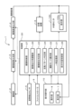
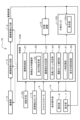
- FIG. 1 is a block diagram schematically showing a standard photography support device according to a first embodiment of the present invention.
- FIG. 2(a) is an external view of the standard photography support device of FIG. 1 viewed from the front.
- FIG. 2(b) is a schematic diagram of the standard photography support device of FIG. 1 viewed from the side.
- FIG. 2 is a schematic diagram showing a method of photographing an upper jaw using the standard photographing support device of FIG. 1;
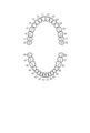
- FIG. 3 is a schematic diagram of the correspondence between the tooth row to be imaged and the tooth type number.
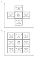
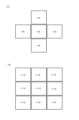
- FIG. 5(a) is a schematic diagram showing the correspondence between imaged regions and tooth type numbers using the five-image method.
- FIG. 5(b) is a schematic diagram showing the correspondence between imaged regions and tooth type numbers using the nine-image method.
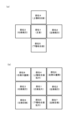
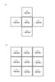
- FIG. 6(a) is a schematic diagram showing names of regions to be imaged using the five-image method.
- FIG. 6(b) is a schematic diagram showing names of regions to be imaged using the nine-image method.
- FIG. 7(a) is an example of a screen display of the standard shooting mode button.
- FIG. 7(b) is an example of a screen display of the acquisition number input button.
- FIG. 7(c) is an example of a screen display of the imaging region setting button.
- FIG. 8(a) is an example of a screen display of buttons in the specific part setting section of the 5-sheet method.
- FIG. 8(b) is an example of a screen display of buttons in the specific part setting section of the 9-sheet method.
- FIG. 8(c) is an example of a screen display of the specific region information notification area of the five-sheet method.
- FIG. 8(d) is an example of a screen display of the specific part information notification area of the 9-sheet method.
- FIG. 9(a) is a schematic diagram showing the correspondence between imaged regions and posture detection sensor outputs using the five-image method.
- FIG. 9(b) is a schematic diagram showing the correspondence between imaged regions and posture detection sensor outputs using the nine-image method.
- FIG. 10(a) is a schematic diagram showing the correspondence between imaged regions and inversion processing using the five-image method.
- FIG. 10(b) is a schematic diagram showing the correspondence between imaged regions and inversion processing using the nine-image method.
- FIG. 11(a) is a schematic diagram showing the correspondence between imaged regions and magnification ratios using the five-image method.
- FIG. 11(b) is a schematic diagram showing the correspondence between imaged regions and magnification ratios using the 9-image method.
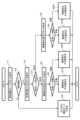
- 3 is a flowchart showing the flow of processing in the standard photography mode of the standard photography support device according to the embodiment of the present invention.
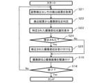
- 13 is a flowchart showing the flow of manual setting of the imaging region in FIG. 12.
- FIG. 13 is a flowchart showing the flow of automatic setting of the imaging region in FIG. 12.
- FIG. FIG. 2 is a block diagram schematically showing a standard photography support device according to a second embodiment of the present invention.
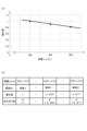
- FIG. 16(a) is a graph showing correction values according to distance.
- FIG. 16(b) is a region enlargement ratio table.
- FIG. 17(a) is a schematic diagram showing the correspondence between imaged regions and magnification correction values using the five-image method.
- FIG. 17(b) is a schematic diagram showing the correspondence between imaged regions and magnification correction values using the nine-image method.
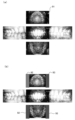
- FIG. 18(a) is a captured image before masking processing.
- FIG. 18(b) is a captured image after masking processing.
- a standard imaging support device 1 according to the first embodiment shown in FIG. 1 is an apparatus that has a standard imaging mode for imaging the inside of the oral cavity of a patient and supports standard imaging by a user.
- the standard photography support device 1 includes an imaging section 2, a captured image generation section 3, a captured image output section 4, an attitude detection sensor 5, a storage device 6, a display section 7, an operation section 8, and a foot controller 9. and a control section 20.
- the display section 7 and the operation section 8 may be integrated to form a display operation section 10 consisting of a touch panel.
- FIGS. 2(a) and 2(b) An example of a standard photography support apparatus 1 including a display operation section 10 consisting of a touch panel is shown in FIGS. 2(a) and 2(b).
- FIG. 2(a) is an external view of the standard photography support device 1 viewed from the front.
- the standard photography support device 1 includes a main body portion 31, a grip portion 32, and an arm connection portion 33, as shown in FIG. 2(a).
- the main body section 31 is a housing that houses the imaging section 2, the captured image generation section 3, the captured image output section 4 (hereinafter collectively referred to simply as a camera), and the control section 20.
- a display/operation section 10 is formed on the front of the main body 31, and a light is provided at the bottom of the main body 31 to illuminate the camera lens and the subject in a downwardly facing state.
- the display and operation section 10 is, for example, a touch panel, and serves as both the display section 7 and the operation section 8.
- the grip part 32 is a curved rod-shaped handle that is gripped by the user when moving the standard photography support device 1 to a desired position, and is provided at the lower left side and the lower right side of the main body 31.
- the arm connection section 33 is a means for connecting and fixing the main body section 31 of the standard photographic support device 1 to a stand or a hanger of a predetermined height.
- FIG. 2(b) is a schematic diagram of the standard photography support device 1 viewed from the side, showing the situation during photography.
- the user 101 is a dentist, dental hygienist, or the like.
- the patient 102 is asked to lie down on a dental chair and open his/her mouth while lying on his/her back.
- the standard photography support device 1 is connected and fixed to the tip of an arm 104 extending horizontally from a stand 103.
- the stand 103 is a stand that stands alone or a pole fixed to a dental unit (not shown).
- FIG. 3 is a schematic diagram showing a method of photographing the upper jaw using the standard photographing support device 1. In this way, the user 101 uses the mirror 105 to photograph the image reflected on the mirror 105 depending on the part to be imaged.
- the imaging unit 2 includes a camera lens and an image sensor.
- the image sensor is, for example, a CCD (Charge-Coupled Device) image sensor, a CMOS (Complementary MOS) image sensor, or the like.
- the imaging unit 2 performs imaging in response to a control signal from the control unit 20.
- the imaging unit 2 converts the captured image into an electrical signal (image signal) and outputs it to the captured image generation unit 3.
- the captured image generation section 3 generates a captured image based on the image signal output from the imaging section 2.
- the captured image generation section 3 outputs the captured image generated from the image signal to the captured image output section 4.
- the captured image output unit 4 performs inversion processing on the acquired captured image and outputs it to the display unit 7, external monitor 100, and storage device 6, respectively.
- the captured image output unit 4 outputs the data of the captured image that has been subjected to the inversion process in a format that includes information regarding the imaged region of the acquired imaging target.
- the format that includes information regarding the region to be imaged is, for example, the DICOM format.
- DICOM is an abbreviation for “Digital Imaging and Communications in Medicine” and is an international standard that defines image standards and communication protocols for medical images.
- the DICOM tag (0008,2228) also represents the primary anatomical structure sequence.
- the captured image output unit 4 saves the standard photographed photograph in DICOM format, and records the tooth type number (see FIGS. 4, 5(a), and 5(b)) in the DICOM tag (0008, 2228). The area to be imaged can be determined from this dental number.
- FIG. 4 shows, as an example, the correspondence between tooth type numbers and tooth rows to be imaged using the FDI method (two-digit system).
- FIG. 5(a) is a schematic diagram showing the correspondence between imaged regions and tooth type numbers using the five-image method.
- FIG. 5(b) is a schematic diagram showing the correspondence between imaged regions and tooth type numbers using the nine-image method.
- the names of parts 1 to 5 shown in FIG. 6(a) are front, left lateral, right lateral, upper occlusal surface, and lower occlusal surface, respectively.
- the names of parts 1 to 9 shown in Fig. 6(b) are front, left lateral, right lateral, upper occlusal surface expansion, mandibular occlusal surface expansion, left palatal side, and left lingual side, respectively. side, right palatal side, and right lingual side.
- the front image will include teeth with tooth type numbers 11 to 15, 21 to 25, 41 to 45, and 31 to 35, as shown in Figure 5(a). Since this is a captured image, the captured image output unit 4 records the following character string in the DICOM tag (0008, 2228). "15 ⁇ 14 ⁇ 13 ⁇ 12 ⁇ 11 ⁇ 21 ⁇ 22 ⁇ 23 ⁇ 24 ⁇ 25 ⁇ 45 ⁇ 44 ⁇ 43 ⁇ 42 ⁇ 41 ⁇ 31 ⁇ 32 ⁇ 33 ⁇ 34 ⁇ 35" In the above example, all tooth type numbers are listed, but only some tooth type numbers, such as 11 and 12, may be recorded. Note that the system is not limited to the FDI system, and the American system (Universal system) or Zsigmondy system (Zsigmondy & Palmer system) may be adopted.
- the attitude detection sensor 5 detects the three-dimensional attitude of the imaging unit 2 with respect to the reference attitude of the imaging unit 2.
- the attitude detection sensor 5 detectors using various methods for detecting three-dimensional posture can be used.
- the attitude detection sensor 5 may be, for example, a gyro sensor, an acceleration sensor, a geomagnetic sensor, etc., as long as it can detect the attitude of three axes. Further, the attitude detection sensor 5 may be configured by combining a gyro sensor and an acceleration sensor, for example.
- the attitude detection sensor 5 may be composed of one semiconductor chip.
- the posture detection sensor 5 is installed, for example, near the imaging section 2. Note that the position of the attitude detection sensor 5 is not limited to the vicinity of the imaging unit 2 as long as the attitude of the imaging unit 2 can be detected.
- the posture detected by the posture detection sensor 5 is expressed as a three-dimensional angle.
- the posture detection sensor 5 outputs the detected angle to the control unit 20.
- the storage device 6 stores the data of the captured image output from the captured image output unit 4.
- Storage device 6 is an image memory.
- the storage device 6 may be, for example, a storage means (HDD) of a general personal computer, an externally connected HDD, or an image storage server connected to the standard photography support device 1 via a network.
- the display unit 7 displays the captured image output from the captured image output unit 4.
- the display section 7 is composed of, for example, a liquid crystal display panel.
- the operation unit 8 accepts a shooting mode setting operation from the user.
- the operation unit 8 has buttons through which instructions can be input by user operation.
- the operation section 8 having buttons means that, for example, in the case of the display operation section 10 consisting of a touch panel, when buttons are displayed on the screen, it is clear that the operation section 8 has buttons. It is. Furthermore, even if the display of the buttons is canceled from the screen, the touch panel can display the buttons again, and even if the display of the buttons is canceled, it can be said that the touch panel is substantially equipped with buttons.
- the buttons on the operation unit 8 may be, for example, mechanical switches (including sheet switches) in addition to the buttons displayed on the touch panel.
- the operation section 8 will be described as having the same meaning as the display operation section 10 consisting of a touch panel, as an example.
- FIGS. 7(a) to 7(c) are examples of buttons displayed on the display/operation section 10 (operation section 8) consisting of a touch panel.
- the display operation section 10 has a standard shooting mode button B02.
- the standard photography mode button B02 is a button that allows input of a standard photography mode execution instruction for executing the standard photography mode.
- a normal photography mode button B01 and a standard photography mode button B02 are displayed simultaneously on the screen of the display operation unit 10.
- the normal shooting mode button B01 is a button for selecting normal shooting other than standard shooting.
- the normal imaging is, for example, root canal imaging or imaging of a treatment site of one tooth.
- the display operation section 10 has acquisition number input buttons B03 and B04.
- the acquisition number input buttons B03 and B04 are used to select whether to execute the 5-exposure method acquisition mode, in which images captured using the 5-exposure method of standard photography are acquired, or the 9-exposure method, in which images captured using the 9-exposure method of standard photography are acquired.
- This is a button that allows you to input whether to execute the acquisition mode.
- the acquisition number input button B03 is a button for selecting the five-image standard shooting
- the acquisition number input button B04 is a button for selecting the nine-image standard shooting.
- the display operation section 10 has imaging site setting buttons B05 and B06.
- the imaging site setting buttons B05 and B06 are used to determine which of the multiple imaging sites specified in the patient's oral cavity the imaging site of the captured image that the standard imaging support device 1 attempts to acquire is for. This button allows you to input whether to set automatically or manually.
- the imaging region setting button B05 is a button for selecting a method for automatically setting the imaging region based on the detection result of the orientation of the imaging unit 2 by the orientation detection sensor 5.
- the imaging site setting button B06 is a button for the user to select a method for specifying (manual setting) the imaging site.
- the display operation section 10 has a specific region setting section 81.
- the specific region setting unit 81 inputs, through a user operation, which of the plurality of imaging regions specified in the patient's oral cavity is the imaging region of the captured image that the standard imaging support device 1 attempts to acquire. This is a possible setting section.
- the specific region setting section 81 is composed of five buttons corresponding to the imaging regions of the five-frame method of standard imaging, and these five buttons are arranged in a cross shape. . These five buttons may be arranged in a cross shape when viewed from the user. Here, the five buttons are arranged two-dimensionally in a cross shape on the display operation section 10, for example.
- the specific region setting section 81 is composed of nine buttons that respectively correspond to the imaging regions in the nine-frame method of standard imaging, and these nine buttons can be used, for example, on the display operation section. 10, two-dimensionally arranged in a matrix of three columns and three rows.
- Each button constituting the specific part setting section 81 is specific part corresponding image information corresponding to each of a plurality of imaging parts, and is a captured image that the standard imaging support device 1 attempts to obtain or a captured image that the standard imaging support device 1 attempts to acquire. The acquired captured image is displayed on the display operation section 10 (display section 7).
- the display operation section 10 has a specific region information notification area 71.
- the specific region information notification area 71 indicates which imaged image the standard imaging support device 1 is trying to acquire, or which imaged region of the plurality of imaged regions specified in the oral cavity of the patient the imaged region of the captured image is. This is an area for notifying.
- each region constituting the specific region information notification region 71 is image information corresponding to a plurality of imaged regions, which the standard imaging support device 1 attempts to acquire.
- the captured image or the captured image acquired by the standard photography support device 1 is displayed on the display unit 7.
- the specific site information notification area 71 is composed of five areas corresponding to the imaged areas in the five-frame method of standard photography, and these five areas are, for example, They are arranged two-dimensionally in a cross shape on the top.
- FIG. 8C is an example in which the specific site information notification area 71 provides notification in a manner that allows the standard imaging support device 1 to identify that the imaged site that it is attempting to acquire is a frontal imaged site.
- the specific part information notification area 71 may be configured such that the specific area can be identified by, for example, changing the display color, increasing the light intensity, or blinking the specific area.
- the specific site information notification area 71 is composed of nine areas corresponding to the imaged areas in the nine-frame method of standard imaging, and these nine areas are, for example, They are arranged two-dimensionally in a matrix of three columns and three rows. Note that FIG. 8(d) is also an example in which the specific part information notification area 71 provides notification so that it can be identified that the imaging part that the standard imaging support apparatus 1 attempts to acquire is a front imaging part.
- the foot controller 9 is used to input predetermined instructions to the standard photography support device 1.
- the foot controller 9 may include a pedal, and the user may input an instruction to start photographing, for example, by depressing the pedal.
- the foot controller 9 may be configured to input an instruction to select or determine an imaging region, for example.
- the foot controller 9 is sanitary because it can be operated without using hands.
- the control unit 20 executes the standard photographing mode.
- the control section 20 includes a temporary storage section 21, an imaging mode selection section 22, an imaging region determination section 23, an inversion pattern determination section 24, a display content control section 25, and an image enlargement rate adjustment section. section 26 and an imaging control section 27.
- the temporary storage section 21 temporarily stores calculation results calculated by each section of the control section 20, and is, for example, a RAM (Random Access Memory).
- the shooting mode selection section 22 performs processing for determining the shooting mode setting operation received by the operation section 8, and processing for displaying various types of corresponding image information on the display operation section 10 according to this judgment processing. be.
- the imaging mode selection section 22 displays, for example, a normal imaging mode button B01, a standard imaging mode button B02, acquisition number input buttons B03, B04, imaging region setting buttons B05, B06, a specific region setting section 81, etc. on the display operation section 10. let Furthermore, when the imaging mode selection section 22 is notified of information about the imaging region to be imaged from the imaging region determination section 23, the imaging mode selection section 22 makes it possible to identify an area corresponding to the imaging region in the specific region information notification area 71. It is displayed on the display operation section 10.
- the imaged region determining unit 23 uses the posture detection sensor 5 to detect which of the plurality of imaged regions identified in the patient's oral cavity the imaged region of the captured image that the standard imaging support device 1 attempts to acquire is. Judgment is made based on the results.
- the imaged region determining unit 23 determines the region to be imaged for each image capturing based on the detection result of the posture detection sensor 5 and predetermined determination conditions. For example, the determination conditions shown in FIGS. 9(a) and 9(b) may be adopted.
- FIG. 9(a) shows the determination conditions for the 5-sheet method
- FIG. 9(b) shows the determination conditions for the 9-sheet method.
- the imaged region determination unit 23 determines that the imaged region is region 2. In this case, the imaging region determination unit 23 notifies the imaging mode selection unit 22 of the determination result of the imaging region (information that the region to be imaged is region 2).
- the imaged region determination unit 23 determines that the imaged region is region 3. If the difference in the output from the posture detection sensor 5 is ⁇ 30° ⁇ X ⁇ +30° and Y ⁇ +5°, the imaged region determination unit 23 determines that the imaged region is region 4. If the difference in the output from the posture detection sensor 5 is ⁇ 30° ⁇ X ⁇ +30° and Y ⁇ 25°, the imaged region determining unit 23 determines that the imaged region is the region 5.
- the imaged region determining unit 23 determines that the imaged region is the region 6.
- the imaged region determining unit 23 determines that the imaged region is the region 7.
- the imaged region determining unit 23 determines that the imaged region is the region 8.
- the imaged region determining unit 23 determines that the imaged region is the region 9.
- the reversal pattern determining unit 24 determines which of a plurality of predetermined reversing processes should be performed on a captured image obtained with an arbitrary imaging region as an imaging target for each imaging using the 5-image method or the 9-image method. Determine if there is.
- the correspondence tables shown in FIGS. 10(a) and 10(b) may be employed as the plurality of inversion processes.
- FIG. 10(a) shows a correspondence table for the 5-sheet method
- FIG. 10(b) shows a correspondence table for the 9-sheet method.
- FLIP indicates vertical reversal processing
- REV indicates horizontal reversal processing.
- the reversal pattern determination section 24 determines that the captured image of the selected imaging region is , it is determined that vertical and horizontal reversal processing (FLIP & REV) is necessary.
- the determination result of the imaged region determination section 23 specifies intraoral region 2 (left lateral)
- the inversion pattern determination section 24 performs vertical inversion processing on the captured image of the specified imaging region. (FLIP) is determined to be necessary.
- the reversal pattern determination unit 24 outputs the determination result (the reversal processing content of the imaged region or information specifying the reversal processing content) to the captured image output unit 4, for example, via the imaging control unit 27 or directly. .
- the captured image output unit 4 performs inversion processing on the acquired captured image based on the determination result of the inversion pattern determination unit 24 and outputs the result.
- the captured image output unit 4 outputs the captured image subjected to the inversion process to the display operation unit 10, external monitor 100, and storage device 6, respectively. Note that depending on the imaging method, there may be cases where an imaged part does not require inversion processing, but in the embodiment, the term inversion processing includes the case where there is an imaging part that does not undergo such inversion processing.
- the display content control unit 25 controls the display content on the screen of the display operation unit 10.
- the display content control section 25 causes the display operation section 10 to display the captured image of the specific imaged region acquired by the imaging section 2 by replacing it with specific region corresponding image information corresponding to the specific imaged region.
- the image information corresponding to a specific region refers to an image of a button indicating an imaged region in the oral cavity, for example, from the front.
- the display content control unit 25 acquires the captured image output from the captured image output unit 4.
- the captured image to be acquired is a captured image of a specific imaged part of the imaging target.
- the standard photography support device 1 is connected to an external monitor 100, and the display content control unit 25 controls the display content on the screen 100a of the external monitor 100 connected to the standard photography support device 1. You can also do that.
- the display content control unit 25 displays the captured image of the specific imaged region acquired by the imaging unit 2 on the screen 100a of the external monitor 100 by replacing it with specific region corresponding image information corresponding to the specific imaged region.
- the external monitor 100 is a large monitor with high image quality. It is preferable that the external monitor 100 is, for example, a monitor of 4K or higher and 50 inches or higher. By doing so, the content displayed on the screen 100a of the external monitor 100 becomes easier for the user to view than the content displayed on the screen of the display operation unit 10 at hand.
- the display content control unit 25 replaces the captured image, which has been subjected to inversion processing corresponding to the specific imaged region, with image information corresponding to the specific region. Specifically, when a captured image using the five-frame method of standard photography is acquired, a part indicating a button corresponding to intraoral part 1 (front) of the specific part setting section 81 shown in FIG. 8(a) is used. The corresponding image information is displayed on the screen of the display operation unit 10 in place of the front captured image that has been subjected to vertical inversion processing and horizontal inversion processing. A similar image is also displayed on the screen 100a of the external monitor 100.
- the image magnification adjustment unit 26 adjusts the magnification of the captured image in the standard photography mode, depending on the area to be imaged in the 5-frame method or the 9-frame method, for each photograph. It is assumed that the enlargement ratio of the captured image using the five-frame method of standard photography is 8 times as shown in FIG. 11(a). As shown in FIG. 11(b), the enlargement ratio of the captured image using the 9-frame method of standard imaging is assumed to be 12 times or 16 times depending on the imaged region.
- the image magnification adjustment unit 26 adjusts the magnification of the captured image to be obtained for the imaged region in response to information indicating the imaged region inputted to the specific region setting unit 81 by the user's operation. For example, when the 9-image method is selected and intraoral region 1 (front) is selected in the specific region setting section 81 of the display operation section 10, a captured image of the selected imaging region Adjust the magnification to 12x.
- the image magnification adjustment unit 26 adjusts the magnification of the captured image that the standard photography support device 1 attempts to acquire, in accordance with the notified specific site information notification area 71. For example, when the 9-image method is selected and the imaging region determination unit 23 determines that the imaging region is intraoral region 4 (maxillary occlusal surface enlargement), the intraoral region The area corresponding to part 4 is identifiably notified. In this case, the image magnification adjustment unit 26 adjusts the magnification rate of the captured image for the imaging region corresponding to the intraoral region 4 to 16 times.
- the imaging control unit 27 controls the imaging unit 2 to take an image of the imaging target according to a user operation.
- the imaging control section 27 outputs control signals to the imaging section 2, the captured image generation section 3, the captured image output section 4, and the storage device 6, respectively, and outputs control signals to the imaging section 2, the captured image generation section 3, the captured image output section 4, and controls the operation of the storage device 6, respectively.
- the standard photography support device 1 causes the photography mode selection unit 22 of the control unit 20 to display the standard photography mode button B02 on the display operation unit 10 (step S1), and determines whether or not an instruction to perform standard photography has been input. (Step S2). If an instruction to perform other than standard photography is input (step S2: No), the photography mode selection unit 22 sets another photography mode (step S9).
- Other shooting modes refer to, for example, normal shooting mode.
- the shooting mode selection unit 22 displays the acquisition number input buttons B03 and B04 on the display operation unit 10 (step S3), and It is determined which of the sheet number input buttons B03 and B04 has been operated (step S4).
- the imaging mode selection section 22 displays the imaging region setting buttons B05 and B06 on the display operation section 10 (step S5). Then, the imaging mode selection unit 22 determines which of the imaging region setting buttons B05 and B06 has been operated (step S6).
- Step S7A if the user operates the imaging region setting button B06 that instructs manual setting when the 5-image method is selected, the imaging mode selection unit 22 performs manual setting of the imaging region using the 5-image method. Further, when the imaging region setting button B06 for instructing manual setting is operated while the 9-image method is selected, the imaging mode selection unit 22 performs manual setting of the imaging region using the 9-image method (step S7B). ). Details of these steps S7A and S7B will be described later.
- Step S8A if the user operates the imaging region setting button B05 that instructs automatic setting while the 5-image method is selected, the imaging mode selection unit 22 automatically sets the imaging region using the 5-image method. If the imaging region setting button B05, which instructs automatic setting, is operated while the 9-image method is selected, the imaging mode selection unit 22 automatically sets the imaging region using the 9-image method (step S8B). ). Details of these steps S8A and S8B will be described later.
- the imaging mode selection section 22 causes the display operation section 10 to display five buttons as the specific region setting section 81 (step S12).
- the imaging mode selection section 22 causes the display operation section 10 to select a region corresponding to the identified imaging region.
- the buttons are displayed so that they can be identified (step S14).
- the imaging mode selection unit 22 associates the imaged region with the imaged image at this time (step S16).
- the standard photography support device 1 performs an inversion process on the captured image corresponding to the imaged region through the processing of the control unit 20 (inversion pattern determination unit 24 and display content control unit 25) and the captured image output unit 4.
- the captured image subjected to the inversion process is displayed on the display operation unit 10, for example.
- the photographing mode selection unit 22 determines whether a predetermined termination condition is satisfied (step S18). For example, the termination condition is satisfied when the imaged region of the five-image method is associated with each of the five captured images, or when an instruction to terminate imaging is input. If the end condition is not satisfied (step S18: No), the shooting mode selection unit 22 returns to step S12. If the termination condition is satisfied (step S18: Yes), the imaging mode selection unit 22 ends the setting of the imaging region.
- the manual setting of the imaged region in the 9-image method (step S7B) is the same as the flow shown in FIG. 13, so a description thereof will be omitted.
- the manual setting of the imaging region in the nine-image method nine buttons are displayed on the display operation section 10 as buttons of the specific region setting section 81.
- the standard photography support device 1 acquires the detection result of the posture detection sensor 5 by the imaged region determining section 23 of the control section 20 (step S21), and determines the imaged region from the detection result of the posture detection sensor 5 (step S22). , outputs information on the determined imaging region to the imaging mode selection section 22.
- the imaged region determination unit 23 stores the detection result of the posture detection sensor 5 obtained during frontal imaging as a reference value.
- the imaging mode selection unit 22 causes the display operation unit 10 to display five areas as the specific site information notification area 71, and displays the area so that the area of the imaged site specified from the detection result of the posture detection sensor 5 can be identified. (Step S23).
- the imaging mode selection unit 22 accepts the modified imaging region (step S25). ), the corrected imaged region and the captured image are associated (step S16).
- step S24: No if the user does not modify the identified imaging region (step S24: No), the imaging mode selection unit 22 proceeds to step S16 and associates the identified imaging region with the captured image. Then, the photographing mode selection unit 22 determines whether a predetermined termination condition is satisfied (step S18). If the termination condition is not met (step S18: No), the standard photography support device 1 returns to step S21. If the end condition is satisfied (step S18: Yes), the standard imaging support device 1 ends the setting of the imaging region.
- the automatic setting of the imaging region in the 9-image method (step S8B) is the same as the flow shown in FIG. 14, so a description thereof will be omitted. In addition, in the automatic setting of the imaging region using the nine-image method, nine regions are displayed as the specific region information notification region 71 on the display operation unit 10.
- the standard photography support apparatus 1B is different from the standard photography support apparatus 1 in that it includes a distance measuring means 60 and a magnification setting section 28 in the control section 20B.
- the distance measuring means 60 measures the distance between the standard photography support device 1B and the object to be imaged. Note that “measuring the distance” does not only mean measuring the actual distance between the standard photography support device 1B and the object to be imaged, but also, for example, measuring the actual distance between the standard photography support device 1B and the object to be imaged by image recognition. It also includes estimating the distance between.
- the distance measuring means 60 includes, for example, a distance measuring sensor (ultrasonic type, laser beam type), image recognition means (camera, image processing unit, control unit, etc.), or an AF (autofocus) mechanism (including a control unit). Point.
- the distance measuring means 60 When the distance measuring means 60 is a distance measuring sensor, the distance between the standard photography support device 1 and the imaging target is the distance between the ranging sensor and the imaging target.
- the distance measuring means 60 When the distance measuring means 60 is an image recognition means, the distance between the standard photography support device 1 and the object to be imaged is the distance between the lens of the camera and the object to be imaged.
- the distance measuring means 60 is an AF mechanism (including a control unit)
- the distance between the standard photography support device 1 and the imaging target is the distance between the camera lens and the imaging target, or the distance between the AF sensor and the imaging target. Refers to the distance between you and the target.
- the distance measuring means 60 outputs the measured distance to the image magnification adjustment section 26 (magnification rate setting section 28).
- the distance measuring means 60 is a distance measuring sensor, and the distance measuring sensor has a function of irradiating colored light to an imaging target. Since the distance measurement sensor uses colored light to point and display the imaged area, the user can measure the inside of the examinee's oral cavity without having to take the trouble of looking into the screen of the display operation unit 10 or the screen 100a of the external monitor 100.
- the optical axis direction of the distance means 60 (outgoing direction of colored light), that is, the optical axis direction of the imaging section 2 can be easily grasped.
- the colored light emitted from the distance measurement sensor is, for example, laser light or LED light. Note that the distance measurement sensor may be configured with a dedicated semiconductor IC chip, for example.
- the image magnification adjustment section 26 of the control section 20B includes a magnification rate setting section 28.
- the magnification rate setting unit 28 sets the magnification rate of the captured image to be acquired for the imaging target based on the measurement result of the distance measuring means 60.
- the magnification setting unit 28 is configured to maintain the same magnification of the captured image to be obtained for the imaging target even if the distance between the standard photography support device 1 and the imaging target differs based on the measurement result of the distance measuring means 60. Correct and set the reference magnification ratio so that Here, the standard enlargement ratio is set in advance by a user operation.
- the captured image generation unit 3 adjusts the enlargement rate of the captured image to be acquired for the imaging target based on the enlargement rate set by the enlargement rate setting unit 28.
- FIG. 16(a) shows the correspondence between the distance and the correction value when the distance between the standard photography support device 1 and the subject is set to 300 mm, 400 mm, and 500 mm, respectively, and the intraoral region 1 (front view) is photographed.
- the photographing distance of the imaging unit 2 is 300 to 500 mm
- the reference magnification is 8 times.
- the magnification rate setting unit 28 sets the result of multiplying the reference magnification rate (for example, 8 times) by the correction value as the magnification rate. Note that the correction value when the photographing distance of the imaging unit 2 is the minimum (300 mm) was set to 1 (reference value).
- the relational expression between the distance between the standard photography support device 1 and the object to be imaged and the set magnification rate is such that the distance between the standard photography support device 1 and the object to be imaged increases. It can be seen that it is expressed by a linear function that decreases linearly as Therefore, for example, the magnification rate setting unit 28 calculates the magnification rate by calculation using this linear function each time an image is captured.
- the magnification rate setting unit 28 is not limited to setting the magnification rate using the linear function described above.
- the distance range that can be measured by the distance measuring means 60 may be divided into a plurality of regions, and the distance range may be set to decrease as the distance between the standard photographic support device 1 and the object to be imaged increases. , one region enlargement ratio may be set for each of the plurality of regions. In that case, the magnification rate setting unit 28 sets the magnification rate of the captured image to be acquired for the imaging target using one of the area magnification rates based on the measurement result of the distance measuring means 60.
- FIG. 16(b) is a diagram showing a region enlargement ratio table.
- This area magnification table stores area magnification rates in advance by dividing the photographable distance into areas of 10 mm. In this example, it is assumed that the photographing distance of the imaging unit 2 is 300 to 500 mm, and the reference magnification is 8 times. In this area magnification table, the area magnification rate for area 1 (when distance L is 300 to 310 mm) is 8 ⁇ 1. The region enlargement ratio for region 11 (when distance L is 400 to 410 mm) is 8 ⁇ 0.904. The region magnification ratio for region 21 (when distance L is 500 to 510 mm) is 8 ⁇ 0.817.
- the image magnification adjustment unit 26 adjusts the magnification of the captured image based on a reference magnification, depending on the imaged region. It is assumed that the reference magnification of the captured image using the 5-frame method in standard photography is 8 times as shown in FIG. 17(a). In standard imaging, the standard magnification ratio of the 9-frame image is assumed to be 12 times or 16 times depending on the region to be imaged, as shown in FIG. 17(b).
- the magnification setting unit 28 uses a correction value according to the imaged region in order to correct the standard magnification factor according to the imaged region.
- Correction values 1 to 5 shown in FIG. 17(a) are correction values for parts 1 to 5 in the oral cavity. Further, in the case of the nine-piece method, correction values 1 to 9 shown in FIG. 17(b) are correction values for regions 1 to 9 in the oral cavity.
- correction values 1 to 5 shown in FIG. 17(a) may be set to the same predetermined value ⁇ .
- correction values 1 to 3 shown in FIG. 17(b) may be set to the same predetermined value ⁇ .
- correction values 4 to 9 shown in FIG. 17(b) may be set to the same predetermined value ⁇ .
- the standard photography support device 1B corrects and sets the magnification ratio of each captured image according to the distance between the standard photography support device 1B and the imaging target. It is possible to reduce the effort required to unify the magnification factors among a plurality of captured images.
- the distance measuring means 60 is a distance measuring sensor that irradiates colored light to the imaging target, it may have a configuration that does not include a distance measuring sensor, or a configuration that does not have a ranging sensor. It may be. Not having a distance measurement sensor means that the distance measurement sensor can be attached but has been removed. If the standard photographic support device 1 does not have a distance measurement sensor or does not have a distance measurement sensor, it may use the AF function as a substitute for the distance measurement sensor, or use image recognition to determine the distance to the object to be imaged. You can just make an estimate.
- the imaging unit 2 may capture an image in advance so that the imaging range is wider than the imaging range of the captured image used in standard photography.
- the image magnification adjustment unit 26 may perform trimming processing on the captured image that has been previously captured by the imaging unit 2 to have an imaging range wider than the imaging range of the captured image used in standard photography.
- the image magnification rate adjustment unit 26 may set the magnification rate as follows. That is, the magnification rate setting unit 28 may set the magnification rate of the captured image to be acquired for the imaging target so that the imaging range is wider than the imaging range of the captured image used in standard photography.
- the imaging region determination unit 23 When determining the imaging region using the 9-image method, the imaging region determination unit 23 performs the following operations after imaging the imaging regions corresponding to the central portion and the upper, lower, left, and right portions in the matrix of FIG. 9(b). You may judge.
- the imaging region determination unit 23 determines whether the detection result corresponds to the corner located in the tilted direction.
- the imaged region may be specified. Specifically, for example, if it tilts even slightly to the upper right, it may be determined that the position is at the upper right of the four corners that have not been imaged.
- the captured image output unit 4 may perform a masking process on a portion of the captured image where the mirror 91 is likely to be reflected.
- the captured image output unit 4 outputs, for example, the captured image of region 4 (maxillary occlusal surface) and the captured image of region 5 (mandibular occlusal surface) in the oral cavity, at the left end of the image.
- the portion 92 and the right end portion 93 are subjected to masking processing.
- the masking process only needs to hide the area where the edge of the mirror 91 is likely to be reflected, and may be a process of filling it with a color similar to the color inside the oral cavity or an inconspicuous color, for example.
- the color similar to the color inside the oral cavity is, for example, red or skin color
- the inconspicuous color is, for example, gray.
- buttons on the operation unit 8 are not buttons displayed on the touch panel, they may be, for example, mechanical switches (including sheet switches). If the button on the operation unit 8 is a mechanical switch, all steps for displaying the button in the flowcharts of FIGS. 12 and 13 may be deleted.
- buttons on the operation unit 8 are mechanical switches or buttons displayed on a curved display, even if the five buttons that make up the specific part setting unit 81 are provided on the curved surface, those five buttons However, it is sufficient that they are arranged so that they look like a cross when viewed from the user.
- the specific part information notification area 71 has been described as being displayed on the screen of the operation display unit 10, the specific part information notification area 71 is not limited to this. It may be configured with nine LED lamps arranged in a matrix of three columns and three rows. In this case, when the imaging mode selection section 22 is notified of information about the imaging region to be imaged from the imaging region determining section 23, the imaging mode selection section 22 can identify the LED lamp corresponding to the corresponding imaging region in the specific region information notification area 71. Light it up like this.
- the standard imaging support device 1, 1B When automatically setting the imaging site for the 5-image method or the 9-image method, the standard imaging support device 1, 1B is configured to ensure that the imaging region of the captured image that the standard imaging support device 1, 1B attempts to acquire is within the patient's oral cavity. It is also possible to notify by voice which of the plurality of imaged parts is to be imaged.
- the standard photography support devices 1 and 1B include an imaging section 2, a captured image generation section 3, a captured image output section 4, an attitude detection sensor 5, a storage device 6, a display section 7, Although the foot controller 9 is provided, neither of them is an essential configuration. If the standard photographing support devices 1 and 1B are equipped with at least the operating section 8 and the control sections 20 and 20B, they execute the standard photographing mode according to the setting operation received by the operating section 8, so that the standard photographing support devices 1 and 1B are more standard than before. It can make photography easier.
- the imaging section 2 may be separate, for example, a personal computer to which the imaging section 2 is connected. It may also be configured by a computer.
- the control units 20 and 20B of the personal computer acquire a captured image from the imaging unit 2 and execute the standard photography mode in response to a setting operation received by the operation unit 8, such as a mouse or a keyboard.
- a standard photography support device that is equipped with a photography mode for standard photography to photograph the inside of a patient's oral cavity and supports standard photography by a user, an operation unit that accepts shooting mode setting operations from the user; a control unit that executes a standard imaging mode in which the imaging unit images a plurality of imaging regions specified in the oral cavity of the same patient according to a setting operation received by the operating unit, and associates each of the captured images;
- a standard photography support device comprising: (Additional note 2)
- the operation section is The standard photography support device according to appendix 1, further comprising a standard photography mode button that allows input of a standard photography mode execution instruction for executing the standard photography mode.
- the operation section is It is possible to input whether to execute the 5-element method acquisition mode, which acquires images taken with the 5-piece method of standard photography, or the 9-piece method acquisition mode, which acquires images with the 9-piece method of standard photography.
- the standard photography support device according to Supplementary note 1 or 2, which has a button for inputting the number of acquired images.
- (Additional note 4) further comprising a sensor that detects a three-dimensional orientation of the imaging unit with respect to a reference orientation of the imaging unit,
- the control unit includes an imaged region determination unit that determines which of the plurality of imaged regions the imaged region of the imaged image that the standard photography support device is trying to acquire is based on the detection result of the sensor.
- the standard photography support device according to Supplementary note 1, 2 or 3.
- the operation unit includes a specific site information notification area for notifying the captured image that the standard photography support device is trying to acquire or which of the plurality of imaged sites the imaged site of the captured image is.
- the standard photography support device which has: (Appendix 6)
- the specific region information notification area is composed of five regions each corresponding to an imaged region according to the five-image method of standard imaging,
- the specific part information notification area is composed of nine areas each corresponding to an imaged part according to the nine-image method of standard imaging, The standard photography support device according to appendix 5, wherein the nine areas are arranged in a matrix of three columns and three rows.
- the operation section is As described in Supplementary note 1, 2 or 3, the device has a specific region setting section that allows input of which of the plurality of imaging regions the imaging region of the captured image that the standard imaging support device is attempting to acquire is input. standard photography support equipment.
- the specific region setting section is composed of five buttons each corresponding to the imaging region of the five-image method of standard imaging, The standard photography support device according to appendix 8, wherein the five buttons are arranged in a cross shape.
- the specific region setting section is composed of nine buttons each corresponding to the imaging region in the nine-frame method of standard imaging,
- the control unit includes: an imaging control unit that controls the imaging unit to image the imaging target according to a user operation; Supplementary notes 8 and 9, including an image magnification rate adjustment unit that adjusts the magnification rate of a captured image to be obtained for the imaged area in response to information indicating the imaged area inputted to the specific area setting unit by a user operation; 10.
- the standard photography support device according to item 10.
- the control unit includes: an imaging control unit that controls the imaging unit to image the imaging target according to a user operation;
- the operation section is It is possible to input whether to automatically or manually set which of the plurality of imaged areas the imaged part of the imaged image that the standard imaging support device attempts to acquire belongs to.
- the image magnification adjustment section includes: 13. The standard photography support device according to appendix 11 or 12, further comprising a magnification rate setting unit that sets a magnification rate of a captured image to be acquired for the imaging target based on a measurement result of the distance measuring device.
- the image magnification adjustment section includes: The standard photography support device according to appendix 11 or 12, wherein the imaging unit performs a trimming process on a captured image that has been captured in advance so that the imaging range is wider than the imaging range of the captured image used in standard photography.
- the image magnification adjustment section includes: Standard photography according to supplementary note 15, further comprising a magnification rate setting unit that sets the magnification rate of the captured image to be acquired for the imaging target so that the imaging range is wider than the imaging range of the captured image used in the standard photography. Support equipment. (Appendix 17) the imaging unit; further comprising a captured image generation unit that generates a captured image based on an image signal output from the imaging unit, 17.
- the standard photography support device according to supplementary note 14 or 16, wherein the captured image generation unit adjusts the enlargement rate of the captured image to be acquired for the imaging target based on the enlargement rate set by the enlargement rate setting unit.
- a display operation unit is provided, in which a display unit that displays on a screen a captured image that the standard photography support device attempts to acquire or a captured image that the standard photography support device acquires, and the operation unit are integrally configured.
- a display operation unit is provided, in which a display unit that displays on a screen a captured image that the standard photography support device attempts to acquire or a captured image that the standard photography support device acquires, and the operation unit are integrally configured.
- the standard imaging support device according to appendix 6 or 7, wherein each region constituting the specific region information notification region is image information corresponding to a specific region displayed on the display operation section.
- the control unit includes a display content control unit that controls display content on the screen of the display operation unit, Supplementary note 18 or 19, wherein the display content control unit causes the display operation unit to display a captured image of a specific imaged region acquired by the imaging unit by replacing it with the specific region corresponding image information corresponding to the imaged region.
- Standard photographic support device described in described in .
- the control unit includes a display content control unit that controls display content on a screen of a connected external monitor, Supplementary note 18 or 19. The standard photography support device described in 19.
- the standard imaging support device according to appendix 20 or 21, wherein the display content control unit replaces a captured image that has been subjected to inversion processing corresponding to a specific imaged region with the image information corresponding to the specific region.
- the magnification rate setting unit is configured to set, based on the measurement results of the distance measuring means, the magnification rate of the captured image to be obtained for the imaged object is the same even if the distance between the standard photography support device and the imaged object is different.
- the standard photography support device according to appendix 14, wherein the standard photography support device sets the magnification rate of a captured image to be acquired for the imaging target by correcting a reference magnification rate set in advance by a user operation.
- a measurable distance range is divided by the distance measuring means to set a plurality of areas, one area magnification rate is set for each of the plurality of areas so that it decreases as the distance between the standard photography support device and the imaging target increases;
- the magnification rate setting unit sets the magnification rate of the captured image to be acquired for the imaging target using one of the area magnification rates based on the measurement result of the distance measuring means.
- standard photography support equipment The magnification rate setting unit sets the magnification rate of the captured image to be acquired for the imaging target by referring to the area magnification table in which the area magnification rates are stored in advance. Support equipment.
- an inverted pattern determination unit that determines which one;
- the standard photography support device according to appendix 9, 10, or 11, further comprising a captured image output unit that performs inversion processing on the acquired captured image and outputs the resultant image based on the determination result of the inversion pattern determination unit.
- a captured image output unit that performs inversion processing on the acquired captured image and outputs the resultant image based on the determination result of the inversion pattern determination unit.
- the distance measuring means is a distance measuring sensor, The standard photography support device according to appendix 14, 23, 24, 25, or 26, wherein the distance measurement sensor has a function of irradiating colored light to the imaging target.
Landscapes
- Health & Medical Sciences (AREA)
- Life Sciences & Earth Sciences (AREA)
- Surgery (AREA)
- Engineering & Computer Science (AREA)
- General Health & Medical Sciences (AREA)
- Public Health (AREA)
- Veterinary Medicine (AREA)
- Biomedical Technology (AREA)
- Heart & Thoracic Surgery (AREA)
- Medical Informatics (AREA)
- Molecular Biology (AREA)
- Animal Behavior & Ethology (AREA)
- Nuclear Medicine, Radiotherapy & Molecular Imaging (AREA)
- Pathology (AREA)
- Physics & Mathematics (AREA)
- Biophysics (AREA)
- Optics & Photonics (AREA)
- Radiology & Medical Imaging (AREA)
- Oral & Maxillofacial Surgery (AREA)
- Signal Processing (AREA)
- Dentistry (AREA)
- Endoscopes (AREA)
- Apparatus For Radiation Diagnosis (AREA)
- Studio Devices (AREA)
Abstract
Description
なお、規格撮影ではないが歯科医が口腔内カメラで患者の口腔内を撮影し、モニタに映し出された撮影画像を見ながら診療を行うことは知られている(特許文献1)。
[規格撮影支援装置の構成]
図1に示す第1実施形態に係る規格撮影支援装置1は、受診者の口腔内を撮影する規格撮影の撮影モードを備えユーザによる規格撮影を支援する装置である。規格撮影支援装置1は、撮像部2と、撮像画像生成部3と、撮像画像出力部4と、姿勢検出センサ5と、記憶装置6と、表示部7と、操作部8と、フットコントローラ9と、制御部20と、を備えている。表示部7と操作部8を一体化して、タッチパネルからなる表示操作部10を構成してもよい。タッチパネルからなる表示操作部10を備える規格撮影支援装置1の一例を図2(a)および図2(b)に示す。図2(a)は、規格撮影支援装置1を正面から視た外観図である。規格撮影支援装置1は、図2(a)に示すように、本体部31と、把持部32と、アーム接続部33と、を備えている。
把持部32は、ユーザが規格撮影支援装置1を所望の位置に移動させるときに把持する湾曲した棒状のハンドルであり、本体部31の左の側面下部および右の側面下部に設けられている。把持部32には、主電源、カメラ電源、カメラ照明等の各種のボタン操作スイッチが配置されている。
アーム接続部33は、規格撮影支援装置1の本体部31を、所定高さのスタンドや吊り具に接続して固定するための手段である。
撮像画像生成部3は、撮像部2から出力される画像信号に基づいて撮像画像を生成するものである。撮像画像生成部3は、画像信号から生成した撮像画像を撮像画像出力部4に出力する。
「15\14\13\12\11\21\22\23\24\25\45\44\43\42\41\31\32\33\34\35」
上記の例では、全ての歯式番号を列挙したが、11、12など、一部の歯式番号のみを記録するようにしても良い。なお、FDI方式に限らず、アメリカ式(Universal system)やジグモンディ方式(Zsigmondy & Palmer system)を採用してもよい。
表示部7は、撮像画像出力部4から出力された撮像画像を表示するものである。表示部7は、例えば液晶表示パネル等で構成されている。
なお、操作部8のボタンは、タッチパネルに表示されたボタンのほかに、例えばメカニカルスイッチ(シートスイッチを含む)であってもよい。
以下、操作部8は、一例として、タッチパネルからなる表示操作部10と同じ意味であるものとして説明する。
一時記憶部21は、制御部20の各部で計算された計算結果を一時的に記憶するものであり、例えば、RAM(Random Access Memory)等とされる。
姿勢検出センサ5からの出力の差分がX≧+30°かつ-25°<Y<+5°である場合、撮像部位判定部23は、撮像部位が部位2であると判定する。この場合、撮像部位判定部23は、撮像部位の判定結果(撮像しようとする部位が部位2であるとの情報)を撮影モード選択部22に通知する。
姿勢検出センサ5からの出力の差分がX≦-30°かつ-25°<Y<+5°である場合、撮像部位判定部23は、撮像部位が部位3であると判定する。
姿勢検出センサ5からの出力の差分が-30°<X<+30°かつY≧+5°である場合、撮像部位判定部23は、撮像部位が部位4であると判定する。
姿勢検出センサ5からの出力の差分が-30°<X<+30°かつY≦-25°である場合、撮像部位判定部23は、撮像部位が部位5であると判定する。
姿勢検出センサ5からの出力の差分がX≧+30°かつY≦-25°である場合、撮像部位判定部23は、撮像部位が部位7であると判定する。
姿勢検出センサ5からの出力の差分がX≦-30°かつY≧+5°である場合、撮像部位判定部23は、撮像部位が部位8であると判定する。
姿勢検出センサ5からの出力の差分がX≦-30°かつY≦-25°である場合、撮像部位判定部23は、撮像部位が部位9であると判定する。
反転パターン判定部24は、撮像部位判定部23の判定結果が、口腔内の部位2(左側側方)を特定している場合、特定されている撮像部位の撮像画像には、上下の反転処理(FLIP)が必要であると判定する。
例えば9枚法が選択され、かつ撮像部位判定部23によって撮像部位が口腔内の部位4(上顎咬合面拡大)であると判定した場合、表示操作部10の特定部位情報報知領域71において口腔内の部位4に対応した領域が識別可能に報知される。この場合、画像拡大率調整部26は、口腔内の部位4に対応した撮像領域についての撮像画像の拡大率を16倍に調整する。
次に、規格撮影支援装置1の規格撮影モードの処理の流れについて図12を参照(適宜図1、図7(a)から図7(c)参照)して説明する。規格撮影支援装置1は、制御部20の撮影モード選択部22によって、規格撮影モードボタンB02を表示操作部10に表示させ(ステップS1)、規格撮影を実行する指示が入力されたか否かを判別する(ステップS2)。規格撮影以外を実行する指示が入力された場合(ステップS2:No)、撮影モード選択部22は、その他の撮影モードの設定を行う(ステップS9)。その他の撮影モードは、例えば通常撮影モード等を指す。
次に、図12のステップS7Aの流れについて図13を参照(適宜図1、図8(a)および図8(b)参照)して説明する。撮影モード選択部22は、表示操作部10に特定部位設定部81として5つのボタンを表示させる(ステップS12)。ユーザが、表示操作部10の特定部位設定部81の中から任意のボタンを操作して撮像部位を特定すると、撮影モード選択部22は、表示操作部10に、特定された撮像部位に対応したボタンを識別できるように表示させる(ステップS14)。そして、ユーザが受診者の撮像部位を撮像すると、撮影モード選択部22は、このときの撮像部位と撮像画像を関連付ける(ステップS16)。
一方、9枚法の撮像部位の手動設定(ステップS7B)は、その流れが図13に示した流れと同様なので説明を省略する。なお、9枚法の撮像部位の手動設定においては、表示操作部10に特定部位設定部81のボタンとして9つのボタンが表示される。
次に、図12のステップS8Aの流れについて図14を参照(適宜図1、図8(c)および図8(d)参照)して説明する。規格撮影支援装置1は、制御部20の撮像部位判定部23によって、姿勢検出センサ5の検出結果を取得し(ステップS21)、姿勢検出センサ5の検出結果から撮像部位を判定し(ステップS22)、判定された撮像部位の情報を撮影モード選択部22に出力する。なお、撮像部位判定部23は、正面撮影時に取得した姿勢検出センサ5の検出結果を基準値として記憶する。
一方、9枚法の撮像部位の自動設定(ステップS8B)は、その流れが図14に示した流れと同様なので説明を省略する。なお、9枚法の撮像部位の自動設定においては、表示操作部10に特定部位情報報知領域71として9つの領域が表示される。
次に、図15を参照して、第2実施形態に係る規格撮影支援装置1Bについて説明する。なお、図1に示す規格撮影支援装置1と同じ構成には同じ符号を付して説明を省略する。規格撮影支援装置1Bは、測距手段60を備えていると共に、制御部20Bに拡大率設定部28を備えている点が規格撮影支援装置1と相違する。
測距手段60は、例えば測距センサ(超音波方式、レーザ光方式)、画像認識手段(カメラ、画像処理部、制御部等)、またはAF(オートフォーカス)機構(制御部を含む)などを指す。
測距手段60が測距センサである場合、規格撮影支援装置1と撮像対象との間の距離とは、測距センサと撮像対象との間の距離である。
測距手段60が画像認識手段である場合、規格撮影支援装置1と撮像対象との間の距離は、カメラのレンズと撮像対象との間の距離である。
測距手段60がAF機構(制御部を含む)である場合、規格撮影支援装置1と撮像対象との間の距離は、カメラのレンズと撮像対象との間の距離、または、AFセンサと撮像対象との間の距離等を指す。
測距手段60は、測定した距離を画像拡大率調整部26(拡大率設定部28)に出力する。
図16(b)は、領域用拡大率テーブルを示す図である。この領域用拡大率テーブルは、撮影可能距離を10mmごとの領域に区切って領域用拡大率を予め格納している。この例では、撮像部2の撮影可能距離が300~500mmであり、また、基準となる拡大率が8倍であるものとした。この領域用拡大率テーブルにおいて、領域1(距離Lが300~310mmの場合)の領域用拡大率は、8×1である。領域11(距離Lが400~410mmの場合)の領域用拡大率は、8×0.904である。領域21(距離Lが500~510mmの場合)の領域用拡大率は、8×0.817である。
画像拡大率調整部26は、撮像部位に応じて、基準となる拡大率に基づいて撮像画像の拡大率を調整する。規格撮影において5枚法の撮像画像の基準となる拡大率は、図17(a)に示すように8倍であるものとする。規格撮影において9枚法の撮像画像の基準となる拡大率は、図17(b)に示すように、撮像部位に応じて12倍または16倍であるものとする。
拡大率設定部28は、撮像部位に応じた基準となる拡大率を補正するために、撮像部位に応じた補正値を用いる。図17(a)に示す補正値1~補正値5は、口腔内の部位1~部位5に対する補正値である。また、9枚法の場合、図17(b)に示す補正値1~補正値9は、口腔内の部位1~部位9に対する補正値である。
これに対して、第2実施形態に係る規格撮影支援装置1Bは、当該規格撮影支援装置1Bと撮像対象との間の距離に応じて、各撮像画像の拡大率を補正して設定するので、複数の撮像画像どうしの間で拡大率の統一を図る作業の手間を低減することができる。
このようにすることで、たとえ測距手段60を有していなくても、複数の撮像画像どうしの間で拡大率の統一を図る作業の手間を従来よりも低減するこができる。
受診者の口腔内を撮影する規格撮影の撮影モードを備えユーザによる規格撮影を支援する規格撮影支援装置であって、
ユーザからの撮影モードの設定操作を受け付ける操作部と、
前記操作部で受け付けた設定操作に応じて同一受診者の口腔内で特定される複数の撮像部位を撮像部によって撮像し、前記撮像したそれぞれの撮像画像を関連付ける規格撮影モードを実行する制御部と、を備えることを特徴とする規格撮影支援装置。
(付記2)
前記操作部は、
前記規格撮影モードを実行するための規格撮影モード実行指示が入力可能な規格撮影モードボタンを有している付記1に記載の規格撮影支援装置。
(付記3)
前記操作部は、
規格撮影の5枚法の撮像画像が取得される5枚法取得モードを実行するのか、または、規格撮影の9枚法の撮像画像が取得される9枚法取得モードを実行するのかを入力可能な取得枚数入力ボタンを有している付記1又は2に記載の規格撮影支援装置。
(付記4)
前記撮像部の基準姿勢に対する前記撮像部の3次元的な姿勢を検出するセンサをさらに備え、
前記制御部は、当該規格撮影支援装置が取得しようとする撮像画像の撮像部位が前記複数の撮像部位のどの撮像部位であるのかを前記センサの検出結果に基づいて判定する撮像部位判定部を備えている付記1、2又は3に記載の規格撮影支援装置。
(付記5)
前記操作部は、当該規格撮影支援装置が取得しようとする撮像画像、または、当該撮像画像の撮像部位が前記複数の撮像部位のどの撮像部位であるのか、を報知するための特定部位情報報知領域を有している付記4に記載の規格撮影支援装置。
(付記6)
前記特定部位情報報知領域は、規格撮影の5枚法の撮像部位にそれぞれ対応する5つの領域から構成され、
前記5つの領域は、十字状に配置される付記5に記載の規格撮影支援装置。
(付記7)
前記特定部位情報報知領域は、規格撮影の9枚法の撮像部位にそれぞれ対応する9つの領域から構成され、
前記9つの領域は、縦3列かつ横3行のマトリックス状に配置される付記5に記載の規格撮影支援装置。
(付記8)
前記操作部は、
当該規格撮影支援装置が取得しようとする撮像画像の撮像部位が前記複数の撮像部位のうちのどの撮像部位であるのか入力可能な特定部位設定部を有している付記1、2又は3に記載の規格撮影支援装置。
(付記9)
前記特定部位設定部は、規格撮影の5枚法の撮像部位にそれぞれ対応する5つのボタンから構成され、
前記5つのボタンは、十字状に配置される付記8に記載の規格撮影支援装置。
(付記10)
前記特定部位設定部は、規格撮影の9枚法の撮像部位にそれぞれ対応する9つのボタンから構成され、
前記9つのボタンは、縦3列かつ横3行のマトリックス状に配置される付記8に記載の規格撮影支援装置。
(付記11)
前記制御部は、
ユーザ操作により、撮像対象を前記撮像部に撮像させる制御を行う撮像制御部と、
ユーザ操作により前記特定部位設定部に入力された撮像部位を示す情報に対応して、当該撮像部位について取得しようとする撮像画像の拡大率を調整する画像拡大率調整部を備える付記8、9又は10に記載の規格撮影支援装置。
(付記12)
前記制御部は、
ユーザ操作により、撮像対象を前記撮像部に撮像させる制御を行う撮像制御部と、
報知された前記特定部位情報報知領域に対応して、前記取得しようとする撮像画像の拡大率を調整する画像拡大率調整部を備える付記5、6又は7に記載の規格撮影支援装置。
(付記13)
前記操作部は、
前記規格撮影支援装置が取得しようとする撮像画像の撮像部位が前記複数の撮像部位のうちのどの撮像部位のものなのかを、自動で設定するのか、または、手動で設定するのかを入力可能な撮像部位設定ボタンを有している付記4、5、6、7又は12に記載の規格撮影支援装置。
(付記14)
当該規格撮影支援装置と撮像対象との間の距離を測定する測距手段をさらに備え、
前記画像拡大率調整部は、
前記測距手段の測定結果に基づいて、前記撮像対象について取得しようとする撮像画像の拡大率を設定する拡大率設定部を有する付記11又は12に記載の規格撮影支援装置。
(付記15)
前記画像拡大率調整部は、
前記撮像部が予め撮像範囲を規格撮影で用いられる撮像画像の撮像範囲よりも広く撮像した撮像画像に対してトリミング処理を施す付記11又は12に記載の規格撮影支援装置。
(付記16)
前記画像拡大率調整部は、
前記撮像対象について取得しようとする撮像画像の拡大率を、撮像範囲が前記規格撮影で用いられる撮像画像の撮像範囲よりも広くなるように設定する拡大率設定部を有する付記15に記載の規格撮影支援装置。
(付記17)
前記撮像部と、
前記撮像部から出力される画像信号に基づいて撮像画像を生成する撮像画像生成部と、をさらに備え、
前記撮像画像生成部は、前記拡大率設定部で設定された拡大率により前記撮像対象について取得しようとする撮像画像の拡大率を調整する付記14又は16に記載の規格撮影支援装置。
(付記18)
当該規格撮影支援装置が取得しようとする撮像画像、または、当該規格撮影支援装置が取得した撮像画像、を画面に表示する表示部と、前記操作部とが一体に構成された表示操作部を備え、
前記特定部位設定部を構成する各ボタンは、前記表示操作部の画面に表示される特定部位対応画像情報である付記9又は10に記載の規格撮影支援装置。
(付記19)
当該規格撮影支援装置が取得しようとする撮像画像、または、当該規格撮影支援装置が取得した撮像画像、を画面に表示する表示部と、前記操作部とが一体に構成された表示操作部を備え、
前記特定部位情報報知領域を構成する各領域は、前記表示操作部に表示される特定部位対応画像情報である付記6又は7に記載の規格撮影支援装置。
(付記20)
前記制御部は、前記表示操作部の画面での表示内容を制御する表示内容制御部を備え、
前記表示内容制御部は、前記撮像部により取得した特定の撮像部位についての撮像画像を、当該撮像部位と対応する前記特定部位対応画像情報と置き換えて、前記表示操作部に表示させる付記18又は19に記載の規格撮影支援装置。
(付記21)
前記制御部は、接続された外部モニタの画面での表示内容を制御する表示内容制御部を備え、
前記表示内容制御部は、前記撮像部により取得した特定の撮像部位についての撮像画像を、当該撮像部位と対応する前記特定部位対応画像情報と置き換えて、前記外部モニタの画面に表示させる付記18又は19に記載の規格撮影支援装置。
(付記22)
前記表示内容制御部は、特定の撮像部位に対応した反転処理が施されている撮像画像を前記特定部位対応画像情報と置き換えさせる付記20又は21に記載の規格撮影支援装置。
(付記23)
前記拡大率設定部は、前記測距手段の測定結果に基づいて当該規格撮影支援装置と前記撮像対象との間の距離が異なっても当該撮像対象について取得しようとする撮像画像の拡大率が同様となるように、ユーザ操作により予め設定された基準となる拡大率を補正して前記撮像対象について取得しようとする撮像画像の拡大率を設定する付記14に記載の規格撮影支援装置。
(付記24)
前記測距手段によって測定可能な距離範囲が分割されて複数の領域が設定され、
当該規格撮影支援装置と前記撮像対象との間の距離が増加するに伴い減少するように、前記複数の領域の各々に、1つの領域用拡大率が設定されており、
前記拡大率設定部は、前記測距手段の測定結果に基づいて、前記領域用拡大率のいずれかを用いて、前記撮像対象について取得しようとする撮像画像の拡大率を設定する付記23に記載の規格撮影支援装置。
(付記25)
前記拡大率設定部は、前記領域用拡大率が予め格納されている領域用拡大率テーブルを参照して前記撮像対象について取得しようとする撮像画像の拡大率を設定する付記24に記載の規格撮影支援装置。
(付記26)
当該規格撮影支援装置と前記撮像対象との間の距離と前記設定される拡大率との間の関係式は、当該規格撮影支援装置と前記撮像対象との間の距離が増加するに伴いリニアに減少する1次関数で表され、
前記拡大率設定部は、撮像するにあたって前記1次関数を用いた演算により、前記設定される拡大率を算出する付記23に記載の規格撮影支援装置。
(付記27)
ユーザ操作により前記特定部位設定部に対して入力された撮像部位に対応して、当該撮像部位を撮像対象として取得した撮像画像に施すべき反転処理が、予め用意された複数の反転処理のうちのどれであるのかを判定する反転パターン判定部と、
前記反転パターン判定部の判定結果に基づいて、取得した撮像画像に対し反転処理を施して出力する撮像画像出力部と、をさらに備えている付記9、10又は11に記載の規格撮影支援装置。
(付記28)
前記撮像部位判定部で判定された撮像部位に対応して、当該撮像部位を撮像対象として取得した撮像画像に施すべき反転処理が、予め用意された複数の反転処理のうちのどれであるのかを判定する反転パターン判定部と、
前記反転パターン判定部の判定結果に基づいて、取得された撮像画像に対し反転処理を施して出力する撮像画像出力部と、をさらに備えている付記4に記載の規格撮影支援装置。
(付記29)
前記撮像画像出力部は、前記反転処理が施された撮像画像のデータを、前記取得した撮像対象の撮像部位に関する情報を含んだ形式で出力する付記27又は28に記載の規格撮影支援装置。
(付記30)
前記出力された撮像画像のデータを記憶する記憶装置をさらに備えている付記27、28又は29に記載の規格撮影支援装置。
(付記31)
前記測距手段は、測距センサであり、
前記測距センサは、前記撮像対象に対して有色光を照射する機能を有する付記14、23、24、25又は26に記載の規格撮影支援装置。
2 撮像部
3 撮像画像生成部
4 撮像画像出力部
5 姿勢検出センサ
6 記憶装置
7 表示部
8 操作部
9 フットコントローラ
10 表示操作部
20,20B 制御部
21 一時記憶部
22 撮影モード選択部
23 撮像部位判定部
24 反転パターン判定部
25 表示内容制御部
26,26B 画像拡大率調整部
27 撮像制御部
28 拡大率設定部
31 本体部
32 把持部
60 測距手段
71 特定部位情報報知領域
81 特定部位設定部
100 外部モニタ
100a 画面
B01 通常撮影モードボタン
B02 規格撮影モードボタン
B03,B04 取得枚数入力ボタン
B05,B06 撮像部位設定ボタン
Claims (22)
- 受診者の口腔内を撮影する規格撮影の撮影モードを備えユーザによる規格撮影を支援する規格撮影支援装置であって、
ユーザからの撮影モードの設定操作を受け付ける操作部と、
前記操作部で受け付けた設定操作に応じて同一受診者の口腔内で特定される複数の撮像部位を撮像部によって撮像し、前記撮像したそれぞれの撮像画像を関連付ける規格撮影モードを実行する制御部と、を備えることを特徴とする規格撮影支援装置。 - 前記操作部は、
前記規格撮影モードを実行するための規格撮影モード実行指示が入力可能な規格撮影モードボタンを有している請求項1に記載の規格撮影支援装置。 - 前記操作部は、
規格撮影の5枚法の撮像画像が取得される5枚法取得モードを実行するのか、または、規格撮影の9枚法の撮像画像が取得される9枚法取得モードを実行するのかを入力可能な取得枚数入力ボタンを有している請求項1または請求項2に記載の規格撮影支援装置。 - 前記撮像部の基準姿勢に対する前記撮像部の3次元的な姿勢を検出するセンサをさらに備え、
前記制御部は、当該規格撮影支援装置が取得しようとする撮像画像の撮像部位が前記複数の撮像部位のどの撮像部位であるのかを前記センサの検出結果に基づいて判定する撮像部位判定部を備えている請求項1から請求項3のいずれか一項に記載の規格撮影支援装置。 - 前記操作部は、当該規格撮影支援装置が取得しようとする撮像画像、または、当該撮像画像の撮像部位が前記複数の撮像部位のどの撮像部位であるのか、を報知するための特定部位情報報知領域を有している請求項4に記載の規格撮影支援装置。
- 前記操作部は、
当該規格撮影支援装置が取得しようとする撮像画像の撮像部位が前記複数の撮像部位のうちのどの撮像部位であるのか入力可能な特定部位設定部を有している請求項1から請求項3のいずれか一項に記載の規格撮影支援装置。 - 前記制御部は、
ユーザ操作により、撮像対象を前記撮像部に撮像させる制御を行う撮像制御部と、
ユーザ操作により前記特定部位設定部に入力された撮像部位を示す情報に対応して、当該撮像部位について取得しようとする撮像画像の拡大率を調整する画像拡大率調整部を備える請求項6に記載の規格撮影支援装置。 - 前記制御部は、
ユーザ操作により、撮像対象を前記撮像部に撮像させる制御を行う撮像制御部と、
報知された前記特定部位情報報知領域に対応して、前記取得しようとする撮像画像の拡大率を調整する画像拡大率調整部を備える請求項5に記載の規格撮影支援装置。 - 前記操作部は、
前記規格撮影支援装置が取得しようとする撮像画像の撮像部位が前記複数の撮像部位のうちのどの撮像部位のものなのかを、自動で設定するのか、または、手動で設定するのかを入力可能な撮像部位設定ボタンを有している請求項4、5又は8のいずれか一項に記載の規格撮影支援装置。 - 当該規格撮影支援装置と撮像対象との間の距離を測定する測距手段をさらに備え、
前記画像拡大率調整部は、
前記測距手段の測定結果に基づいて、前記撮像対象について取得しようとする撮像画像の拡大率を設定する拡大率設定部を有する請求項7または請求項8に記載の規格撮影支援装置。 - 前記画像拡大率調整部は、
前記撮像部が予め撮像範囲を規格撮影で用いられる撮像画像の撮像範囲よりも広く撮像した撮像画像に対してトリミング処理を施す請求項7または請求項8に記載の規格撮影支援装置。 - 前記撮像部と、
前記撮像部から出力される画像信号に基づいて撮像画像を生成する撮像画像生成部と、をさらに備え、
前記撮像画像生成部は、前記拡大率設定部で設定された拡大率により前記撮像対象について取得しようとする撮像画像の拡大率を調整する請求項10に記載の規格撮影支援装置。 - 当該規格撮影支援装置が取得しようとする撮像画像、または、当該規格撮影支援装置が取得した撮像画像、を画面に表示する表示部と、前記操作部とが一体に構成された表示操作部を備え、
前記特定部位設定部を構成する各ボタンは、前記表示操作部の画面に表示される特定部位対応画像情報である請求項6に記載の規格撮影支援装置。 - 当該規格撮影支援装置が取得しようとする撮像画像、または、当該規格撮影支援装置が取得した撮像画像、を画面に表示する表示部と、前記操作部とが一体に構成された表示操作部を備え、
前記特定部位情報報知領域を構成する各領域は、前記表示操作部に表示される特定部位対応画像情報である請求項5に記載の規格撮影支援装置。 - 前記制御部は、前記表示操作部の画面での表示内容を制御する表示内容制御部を備え、
前記表示内容制御部は、前記撮像部により取得した特定の撮像部位についての撮像画像を、当該撮像部位と対応する前記特定部位対応画像情報と置き換えて、前記表示操作部に表示させる請求項13または請求項14に記載の規格撮影支援装置。 - 前記制御部は、接続された外部モニタの画面での表示内容を制御する表示内容制御部を備え、
前記表示内容制御部は、前記撮像部により取得した特定の撮像部位についての撮像画像を、当該撮像部位と対応する前記特定部位対応画像情報と置き換えて、前記外部モニタの画面に表示させる請求項13または請求項14に記載の規格撮影支援装置。 - 前記表示内容制御部は、特定の撮像部位に対応した反転処理が施されている撮像画像を前記特定部位対応画像情報と置き換えさせる請求項15または請求項16に記載の規格撮影支援装置。
- 前記拡大率設定部は、前記測距手段の測定結果に基づいて当該規格撮影支援装置と前記撮像対象との間の距離が異なっても当該撮像対象について取得しようとする撮像画像の拡大率が同様となるように、ユーザ操作により予め設定された基準となる拡大率を補正して前記撮像対象について取得しようとする撮像画像の拡大率を設定する請求項10に記載の規格撮影支援装置。
- ユーザ操作により前記特定部位設定部に対して入力された撮像部位に対応して、当該撮像部位を撮像対象として取得した撮像画像に施すべき反転処理が、予め用意された複数の反転処理のうちのどれであるのかを判定する反転パターン判定部と、
前記反転パターン判定部の判定結果に基づいて、取得した撮像画像に対し反転処理を施して出力する撮像画像出力部と、をさらに備えている請求項7に記載の規格撮影支援装置。 - 前記撮像部位判定部で判定された撮像部位に対応して、当該撮像部位を撮像対象として取得した撮像画像に施すべき反転処理が、予め用意された複数の反転処理のうちのどれであるのかを判定する反転パターン判定部と、
前記反転パターン判定部の判定結果に基づいて、取得された撮像画像に対し反転処理を施して出力する撮像画像出力部と、をさらに備えている請求項4に記載の規格撮影支援装置。 - 前記出力された撮像画像のデータを記憶する記憶装置をさらに備えている請求項19または請求項20に記載の規格撮影支援装置。
- 前記測距手段は、測距センサであり、
前記測距センサは、前記撮像対象に対して有色光を照射する機能を有する請求項10または請求項18に記載の規格撮影支援装置。
Priority Applications (1)
| Application Number | Priority Date | Filing Date | Title |
|---|---|---|---|
| EP23774387.7A EP4464234A4 (en) | 2022-03-25 | 2023-02-27 | STANDARD IMAGING ASSISTANCE DEVICE |
Applications Claiming Priority (2)
| Application Number | Priority Date | Filing Date | Title |
|---|---|---|---|
| JP2022-050888 | 2022-03-25 | ||
| JP2022050888A JP7365722B2 (ja) | 2022-03-25 | 2022-03-25 | 規格撮影支援装置 |
Publications (1)
| Publication Number | Publication Date |
|---|---|
| WO2023181788A1 true WO2023181788A1 (ja) | 2023-09-28 |
Family
ID=88100541
Family Applications (1)
| Application Number | Title | Priority Date | Filing Date |
|---|---|---|---|
| PCT/JP2023/006974 Ceased WO2023181788A1 (ja) | 2022-03-25 | 2023-02-27 | 規格撮影支援装置 |
Country Status (4)
| Country | Link |
|---|---|
| EP (1) | EP4464234A4 (ja) |
| JP (1) | JP7365722B2 (ja) |
| TW (1) | TWI846394B (ja) |
| WO (1) | WO2023181788A1 (ja) |
Families Citing this family (1)
| Publication number | Priority date | Publication date | Assignee | Title |
|---|---|---|---|---|
| JP2024004880A (ja) * | 2022-06-29 | 2024-01-17 | キヤノン株式会社 | 撮影支援装置、撮像装置、撮像装置の制御方法 |
Citations (4)
| Publication number | Priority date | Publication date | Assignee | Title |
|---|---|---|---|---|
| JP2005103048A (ja) | 2003-09-30 | 2005-04-21 | Hidehiro Fujie | 歯科診療装置 |
| JP2010284428A (ja) * | 2009-06-15 | 2010-12-24 | Medeia Kk | 口腔内規格写真撮影用カメラ |
| CN207101254U (zh) * | 2017-02-10 | 2018-03-16 | 杭州小安医疗科技有限公司 | 一种带姿态传感装置的电子口腔内窥镜 |
| JP2019155026A (ja) * | 2018-03-16 | 2019-09-19 | 株式会社Nttドコモ | 腔内写真生成装置及び腔内写真生成プログラム |
Family Cites Families (6)
| Publication number | Priority date | Publication date | Assignee | Title |
|---|---|---|---|---|
| US5702249A (en) * | 1995-05-19 | 1997-12-30 | Cooper; David H. | Modular intra-oral imaging system video camera |
| JP4110141B2 (ja) * | 2002-07-03 | 2008-07-02 | 株式会社松風 | 器械装置の制御システム |
| US7494338B2 (en) * | 2005-01-11 | 2009-02-24 | Duane Durbin | 3D dental scanner |
| JP5016311B2 (ja) * | 2005-12-03 | 2012-09-05 | 淳 高橋 | 口腔内パノラマ画像撮像装置、口腔内パノラマ画像撮像システム |
| US10595966B2 (en) * | 2016-11-04 | 2020-03-24 | Align Technology, Inc. | Methods and apparatuses for dental images |
| CN115605124A (zh) * | 2020-05-26 | 2023-01-13 | 登士柏西诺德公司(Us) | 用于多模态软组织诊断的方法和装置 |
-
2022
- 2022-03-25 JP JP2022050888A patent/JP7365722B2/ja active Active
-
2023
- 2023-02-27 WO PCT/JP2023/006974 patent/WO2023181788A1/ja not_active Ceased
- 2023-02-27 EP EP23774387.7A patent/EP4464234A4/en active Pending
- 2023-03-22 TW TW112110577A patent/TWI846394B/zh active
Patent Citations (4)
| Publication number | Priority date | Publication date | Assignee | Title |
|---|---|---|---|---|
| JP2005103048A (ja) | 2003-09-30 | 2005-04-21 | Hidehiro Fujie | 歯科診療装置 |
| JP2010284428A (ja) * | 2009-06-15 | 2010-12-24 | Medeia Kk | 口腔内規格写真撮影用カメラ |
| CN207101254U (zh) * | 2017-02-10 | 2018-03-16 | 杭州小安医疗科技有限公司 | 一种带姿态传感装置的电子口腔内窥镜 |
| JP2019155026A (ja) * | 2018-03-16 | 2019-09-19 | 株式会社Nttドコモ | 腔内写真生成装置及び腔内写真生成プログラム |
Non-Patent Citations (1)
| Title |
|---|
| See also references of EP4464234A4 |
Also Published As
| Publication number | Publication date |
|---|---|
| JP7365722B2 (ja) | 2023-10-20 |
| TWI846394B (zh) | 2024-06-21 |
| EP4464234A1 (en) | 2024-11-20 |
| JP2023143478A (ja) | 2023-10-06 |
| EP4464234A4 (en) | 2025-12-24 |
| TW202344216A (zh) | 2023-11-16 |
Similar Documents
| Publication | Publication Date | Title |
|---|---|---|
| US10485614B2 (en) | Augmented reality system and method for implementing augmented reality for dental surgery | |
| US20160242623A1 (en) | Apparatus and method for visualizing data and images and for controlling a medical device through a wearable electronic device | |
| JP2020127790A (ja) | 統合されたカメラを有する歯科ミラーおよびそのアプリケーション | |
| JP3040997B1 (ja) | 上顎歯寸法決定装置 | |
| KR20150063139A (ko) | 치아의 표면 텍스처를 추정하는 방법 | |
| JP2005000631A (ja) | 歯科口腔測色写真システム | |
| KR20170093445A (ko) | 칼라 패턴을 이용한 치과용 3차원 스캐너 | |
| JP2022508372A (ja) | 口腔内スキャナを使用して3dデータを取得する混合方法 | |
| JP7365722B2 (ja) | 規格撮影支援装置 | |
| JP7240702B2 (ja) | 治療状況イメージングシステム | |
| Tzimpoulas et al. | Clinical photography and documentation after traumatic dental injuries | |
| KR101485359B1 (ko) | 치아촬영용 3면 스캐너 | |
| CN113660914A (zh) | 用于牙科护理的操作灯 | |
| JP2020509890A (ja) | コンピュータ断層撮影および撮影されるボリュームの位置決め | |
| US11883215B2 (en) | Two-way mirror display for dental treatment system | |
| JP2018175722A (ja) | 口腔内写真撮影システム | |
| Mani et al. | Dental photography | |
| JP2024004880A (ja) | 撮影支援装置、撮像装置、撮像装置の制御方法 | |
| JP2021065263A (ja) | 歯科用撮像画像取得装置 | |
| JP2010284428A (ja) | 口腔内規格写真撮影用カメラ | |
| Ito et al. | Standardization in Oral Photography | |
| KR102555564B1 (ko) | 치과용 엑스레이 이미지를 생성하기 위한 방법 및 그를 위한 엑스레이 장치 | |
| Kiran et al. | Digital photography in dentistry. | |
| US20240310709A1 (en) | Laser safety circuitry for intraoral scanners | |
| Yılmaz et al. | Recent photography trends in orthodontics |
Legal Events
| Date | Code | Title | Description |
|---|---|---|---|
| 121 | Ep: the epo has been informed by wipo that ep was designated in this application |
Ref document number: 23774387 Country of ref document: EP Kind code of ref document: A1 |
|
| WWE | Wipo information: entry into national phase |
Ref document number: 2023774387 Country of ref document: EP |
|
| ENP | Entry into the national phase |
Ref document number: 2023774387 Country of ref document: EP Effective date: 20240812 |
|
| WWE | Wipo information: entry into national phase |
Ref document number: 18848197 Country of ref document: US |
|
| NENP | Non-entry into the national phase |
Ref country code: DE |