WO2023181885A1 - 空気調和システム、空気調和装置及び制御方法 - Google Patents
空気調和システム、空気調和装置及び制御方法 Download PDFInfo
- Publication number
- WO2023181885A1 WO2023181885A1 PCT/JP2023/008348 JP2023008348W WO2023181885A1 WO 2023181885 A1 WO2023181885 A1 WO 2023181885A1 JP 2023008348 W JP2023008348 W JP 2023008348W WO 2023181885 A1 WO2023181885 A1 WO 2023181885A1
- Authority
- WO
- WIPO (PCT)
- Prior art keywords
- indoor
- unit
- prediction
- thermostat
- temperature
- Prior art date
- Legal status (The legal status is an assumption and is not a legal conclusion. Google has not performed a legal analysis and makes no representation as to the accuracy of the status listed.)
- Ceased
Links
Images








Classifications
-
- F—MECHANICAL ENGINEERING; LIGHTING; HEATING; WEAPONS; BLASTING
- F24—HEATING; RANGES; VENTILATING
- F24F—AIR-CONDITIONING; AIR-HUMIDIFICATION; VENTILATION; USE OF AIR CURRENTS FOR SCREENING
- F24F11/00—Control or safety arrangements
- F24F11/30—Control or safety arrangements for purposes related to the operation of the system, e.g. for safety or monitoring
-
- F—MECHANICAL ENGINEERING; LIGHTING; HEATING; WEAPONS; BLASTING
- F24—HEATING; RANGES; VENTILATING
- F24F—AIR-CONDITIONING; AIR-HUMIDIFICATION; VENTILATION; USE OF AIR CURRENTS FOR SCREENING
- F24F11/00—Control or safety arrangements
- F24F11/70—Control systems characterised by their outputs; Constructional details thereof
- F24F11/80—Control systems characterised by their outputs; Constructional details thereof for controlling the temperature of the supplied air
- F24F11/86—Control systems characterised by their outputs; Constructional details thereof for controlling the temperature of the supplied air by controlling compressors within refrigeration or heat pump circuits
-
- F—MECHANICAL ENGINEERING; LIGHTING; HEATING; WEAPONS; BLASTING
- F24—HEATING; RANGES; VENTILATING
- F24F—AIR-CONDITIONING; AIR-HUMIDIFICATION; VENTILATION; USE OF AIR CURRENTS FOR SCREENING
- F24F11/00—Control or safety arrangements
- F24F11/30—Control or safety arrangements for purposes related to the operation of the system, e.g. for safety or monitoring
- F24F11/46—Improving electric energy efficiency or saving
-
- F—MECHANICAL ENGINEERING; LIGHTING; HEATING; WEAPONS; BLASTING
- F24—HEATING; RANGES; VENTILATING
- F24F—AIR-CONDITIONING; AIR-HUMIDIFICATION; VENTILATION; USE OF AIR CURRENTS FOR SCREENING
- F24F11/00—Control or safety arrangements
- F24F11/50—Control or safety arrangements characterised by user interfaces or communication
-
- F—MECHANICAL ENGINEERING; LIGHTING; HEATING; WEAPONS; BLASTING
- F24—HEATING; RANGES; VENTILATING
- F24F—AIR-CONDITIONING; AIR-HUMIDIFICATION; VENTILATION; USE OF AIR CURRENTS FOR SCREENING
- F24F11/00—Control or safety arrangements
- F24F11/50—Control or safety arrangements characterised by user interfaces or communication
- F24F11/61—Control or safety arrangements characterised by user interfaces or communication using timers
-
- F—MECHANICAL ENGINEERING; LIGHTING; HEATING; WEAPONS; BLASTING
- F24—HEATING; RANGES; VENTILATING
- F24F—AIR-CONDITIONING; AIR-HUMIDIFICATION; VENTILATION; USE OF AIR CURRENTS FOR SCREENING
- F24F11/00—Control or safety arrangements
- F24F11/62—Control or safety arrangements characterised by the type of control or by internal processing, e.g. using fuzzy logic, adaptive control or estimation of values
- F24F11/63—Electronic processing
- F24F11/64—Electronic processing using pre-stored data
-
- F—MECHANICAL ENGINEERING; LIGHTING; HEATING; WEAPONS; BLASTING
- F25—REFRIGERATION OR COOLING; COMBINED HEATING AND REFRIGERATION SYSTEMS; HEAT PUMP SYSTEMS; MANUFACTURE OR STORAGE OF ICE; LIQUEFACTION SOLIDIFICATION OF GASES
- F25B—REFRIGERATION MACHINES, PLANTS OR SYSTEMS; COMBINED HEATING AND REFRIGERATION SYSTEMS; HEAT PUMP SYSTEMS
- F25B49/00—Arrangement or mounting of control or safety devices
- F25B49/02—Arrangement or mounting of control or safety devices for compression type machines, plants or systems
-
- F—MECHANICAL ENGINEERING; LIGHTING; HEATING; WEAPONS; BLASTING
- F24—HEATING; RANGES; VENTILATING
- F24F—AIR-CONDITIONING; AIR-HUMIDIFICATION; VENTILATION; USE OF AIR CURRENTS FOR SCREENING
- F24F2110/00—Control inputs relating to air properties
- F24F2110/10—Temperature
-
- F—MECHANICAL ENGINEERING; LIGHTING; HEATING; WEAPONS; BLASTING
- F24—HEATING; RANGES; VENTILATING
- F24F—AIR-CONDITIONING; AIR-HUMIDIFICATION; VENTILATION; USE OF AIR CURRENTS FOR SCREENING
- F24F2140/00—Control inputs relating to system states
-
- F—MECHANICAL ENGINEERING; LIGHTING; HEATING; WEAPONS; BLASTING
- F25—REFRIGERATION OR COOLING; COMBINED HEATING AND REFRIGERATION SYSTEMS; HEAT PUMP SYSTEMS; MANUFACTURE OR STORAGE OF ICE; LIQUEFACTION SOLIDIFICATION OF GASES
- F25B—REFRIGERATION MACHINES, PLANTS OR SYSTEMS; COMBINED HEATING AND REFRIGERATION SYSTEMS; HEAT PUMP SYSTEMS
- F25B2600/00—Control issues
- F25B2600/01—Timing
-
- F—MECHANICAL ENGINEERING; LIGHTING; HEATING; WEAPONS; BLASTING
- F25—REFRIGERATION OR COOLING; COMBINED HEATING AND REFRIGERATION SYSTEMS; HEAT PUMP SYSTEMS; MANUFACTURE OR STORAGE OF ICE; LIQUEFACTION SOLIDIFICATION OF GASES
- F25B—REFRIGERATION MACHINES, PLANTS OR SYSTEMS; COMBINED HEATING AND REFRIGERATION SYSTEMS; HEAT PUMP SYSTEMS
- F25B2600/00—Control issues
- F25B2600/02—Compressor control
- F25B2600/025—Compressor control by controlling speed
- F25B2600/0251—Compressor control by controlling speed with on-off operation
-
- F—MECHANICAL ENGINEERING; LIGHTING; HEATING; WEAPONS; BLASTING
- F25—REFRIGERATION OR COOLING; COMBINED HEATING AND REFRIGERATION SYSTEMS; HEAT PUMP SYSTEMS; MANUFACTURE OR STORAGE OF ICE; LIQUEFACTION SOLIDIFICATION OF GASES
- F25B—REFRIGERATION MACHINES, PLANTS OR SYSTEMS; COMBINED HEATING AND REFRIGERATION SYSTEMS; HEAT PUMP SYSTEMS
- F25B2600/00—Control issues
- F25B2600/23—Time delays
Definitions
- the present invention relates to an air conditioning system, an air conditioner, and a control method.
- the air conditioner includes an outdoor unit including an outdoor unit side refrigerant circuit, and a plurality of indoor units each including an indoor unit side refrigerant circuit connected to the outdoor unit through refrigerant piping.
- the air conditioner drives and controls the compressor in the outdoor unit refrigerant circuit according to the air conditioning capacity required by each indoor unit.
- Each indoor unit in the air conditioner is equipped with a room temperature sensor, and the indoor temperature of the air-conditioned space detected by the room temperature sensor is around the set temperature that is the target temperature for air conditioning operation (for example, a temperature within ⁇ 0.5 degrees Celsius of the set temperature). When the temperature reaches , the thermostat is turned off to interrupt the air conditioning operation of the indoor unit, and the thermostat is turned on to continue the air conditioning operation of the indoor unit until the indoor temperature reaches around the set temperature.
- the compressor is activated. In a short time, the indoor temperature becomes close to the set temperature, all indoor units are turned off, and the compressor is stopped. After that, in the air conditioner, when the indoor temperature rises (during cooling operation) or decreases (during heating operation) and the indoor temperature becomes a temperature that is not around the set temperature, one of the indoor units turns on the thermostat and the compressor turns on. will be restarted. Thereafter, the indoor temperature becomes close to the set temperature again in a short period of time, and the compressor is stopped. In this way, the compressor is repeatedly stopped and restarted.
- the compressor in order to reduce power consumption when air conditioning is operated in an air conditioned space with a small air conditioning load, the compressor is continued to be driven at a low rotation speed without stopping and restarting the compressor. can also be considered.
- the air conditioning load in the air-conditioned space is small, even if the compressor is driven at a low rotation speed, the indoor temperature may deviate from the set temperature, which may reduce user comfort.
- one aspect of the present invention is to reduce the number of stops and restarts of the compressor, thereby reducing power consumption related to air conditioning operation while ensuring user comfort.
- the purpose is to provide a harmonized system, etc.
- An air conditioning system includes: an outdoor unit including a compressor; a plurality of indoor units connected to the outdoor unit via refrigerant piping; a control device that controls the outdoor unit and the plurality of indoor units; It has a server device that can communicate with the control device.
- the server device includes a first prediction unit that predicts an indoor temperature of an air-conditioned space in which the plurality of indoor units are installed, using a plurality of operating state quantities related to air conditioning operation; A second prediction for predicting a time when each indoor unit among the plurality of indoor units will turn on the thermostat and a time when the thermostat will turn off using the indoor temperature set and the set temperature that is the target value of the air conditioning operation. It has a section and a.
- the control device includes a control unit that uses the prediction result of the second prediction unit to control driving of the compressor depending on when each indoor unit turns the thermostat ON or the thermostat OFF.
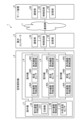
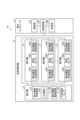
- FIG. 1 is an explanatory diagram showing an example of the configuration of an air conditioning system according to the first embodiment.
- FIG. 2 is a block diagram showing an example of the configuration of a server device.
- FIG. 3 is an explanatory diagram showing an example of feature amounts of a prediction model.
- FIG. 4 is a block diagram showing an example of the configuration of the centralized controller.
- FIG. 5 is an explanatory diagram showing an example of the memory configuration of the memory.
- FIG. 6 is an explanatory diagram showing an example of the prediction result of the amount of change in indoor temperature.
- FIG. 7 is an explanatory diagram showing an example of a prediction result of thermo ON/OFF time.
- FIG. 1 is an explanatory diagram showing an example of the configuration of an air conditioning system according to the first embodiment.
- FIG. 2 is a block diagram showing an example of the configuration of a server device.
- FIG. 3 is an explanatory diagram showing an example of feature amounts of a prediction model.
- FIG. 4 is a block diagram showing an example
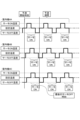
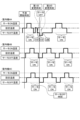
- FIG. 8 is an explanatory diagram showing an example of a variation in power consumption of a compressor due to thermo ON/OFF timing adjustment of each indoor unit in the first embodiment.
- FIG. 9 is an explanatory diagram illustrating an example of a processing operation when specifying the indoor unit whose thermostat will be turned ON first from the predicted start time.
- FIG. 10 is an explanatory diagram showing an example of a processing operation when specifying the indoor unit whose thermostat will be turned off last (reference indoor unit) from the predicted start time.
- FIG. 11 is an explanatory diagram illustrating an example of a processing operation when predicting a first change time and a second change time related to a change in the set temperature of another indoor unit.
- FIG. 12 is an explanatory diagram showing an example of a processing operation when setting the next predicted start time.
- FIG. 13 is a flowchart illustrating an example of processing operations of the centralized controller related to control processing.
- FIG. 14 is a flowchart illustrating an example of processing operations of the centralized controller related to control processing.
- FIG. 15 is a flowchart illustrating an example of processing operations of the centralized controller related to setting processing.
- FIG. 16 is an explanatory diagram showing an example of the configuration of an air conditioner according to the second embodiment.
- FIG. 17 is a block diagram showing an example of the configuration of the centralized controller.
- FIG. 18 is a flowchart illustrating an example of processing operations of the centralized controller related to control processing.
- FIG. 1 is an explanatory diagram showing an example of the configuration of an air conditioning system 1 according to the first embodiment.
- the air conditioning system 1 shown in FIG. 1 includes an air conditioner 2, a central controller 5, and a server device 6.
- the air conditioner 2 has one outdoor unit 3 and N indoor units 4.
- the centralized controller 5 controls the entire air conditioner 2.
- the server device 6 communicates with the centralized controller 5 via the communication network 7 and provides various services to the air conditioner 2 via the centralized controller 5.
- the N outdoor units 3 in the air conditioner 2 are connected to each indoor unit 4 in parallel through, for example, liquid pipes and gas pipes.
- a refrigerant circuit of the air conditioner 2 is formed by connecting the outdoor unit 3 and the indoor unit 4 through refrigerant pipes such as liquid pipes and gas pipes.
- the indoor unit 4 is installed in each indoor space and cools or heats the indoor space.
- the outdoor unit 3 has an outdoor unit side refrigerant circuit 3A, an outdoor unit side control circuit 3B, and an outside air temperature sensor 3C.
- the outdoor unit side refrigerant circuit 3A circulates refrigerant using, for example, a compressor 3A1, and supplies the refrigerant to each indoor unit 4.
- the outdoor unit side control circuit 3B controls the entire outdoor unit 3 including drive control of the compressor 3A1.
- the outside air temperature sensor 3C is a sensor that detects the outside air temperature of the outdoor unit 3.
- each indoor unit 4 has an indoor unit side refrigerant circuit 40A, a room temperature sensor 40B, and an indoor unit side control circuit 40C.
- the indoor unit side refrigerant circuit 40A includes a heat exchanger and the like for exchanging heat with the refrigerant from the outdoor unit 3, and adjusts the indoor temperature of the air-conditioned space with the refrigerant that has passed through the heat exchanger.
- the room temperature sensor 40B is a sensor that detects the room temperature in the air-conditioned space in which the indoor unit 4 is installed.
- the indoor unit side control circuit 40C controls the indoor unit 4 as a whole.
- the indoor unit side control circuit 40C has a function of temporarily stopping the cooling operation, for example, when the indoor temperature reaches a set temperature during the cooling operation.
- the set temperature is a target temperature for air conditioning operation of the indoor unit 4, which is set in the indoor unit 4 by the user.
- the indoor unit side control circuit 40C turns on the thermostat to perform cooling operation of the indoor unit 4 when the indoor temperature exceeds the thermostat ON temperature (set temperature + 0.5° C.) during the cooling operation. Then, the indoor unit side control circuit 40C continues to turn on the thermostat until the indoor temperature reaches the thermostat off temperature (set temperature -0.5° C.) during the thermostat ON period. Further, the indoor unit side control circuit 40C turns the thermostat OFF, interrupting the cooling operation of the indoor unit 4 when the indoor temperature reaches the thermostat OFF temperature.
- the outdoor unit 3 continues to drive the compressor 3A1 in the outdoor unit side refrigerant circuit 3A when any of the indoor units 4 among the N indoor units 4 is in the thermo ON state, whereas all the indoor units 4 continue to drive.
- the driving of the compressor 3A1 is stopped.
- FIG. 2 is a block diagram showing an example of the configuration of the server device 6.
- the server device 6 shown in FIG. 2 includes a communication section 6A, a storage section 6B, and a control circuit 6C.
- the communication unit 6A communicates with the centralized controller 5 via the communication network 7.
- the control circuit 6C controls the entire server device 6.
- the storage unit 6B stores various information.
- the storage unit 6B has a predictive model memory 11.
- the prediction model memory 11 stores a prediction model that predicts a thermo ON time and a thermo OFF time, which are the thermo ON/OFF times of each indoor unit 4, which will be described later.
- the control circuit 6C has a first prediction section 21 and a second prediction section 22.
- the first prediction unit 21 uses a prediction model that uses a plurality of operating state quantities related to air conditioning operation to predict the indoor temperature of an air-conditioned space in which a plurality of indoor units 4 are installed, for example, at a prediction timing every 30 minutes. Predict each room temperature for 30 minutes from the start time.
- the second prediction unit 22 uses the indoor temperature of each indoor unit 4 predicted by the first prediction unit 21 and the set temperature, which is the target value for air conditioning operation, to determine when each indoor unit 4 will turn on the thermostat. Predict the time when the thermostat will turn off. The time when the thermostat is turned on is the thermostat ON time when the indoor unit 4 is thermostatted. The thermostat OFF time is the thermostat OFF time when the indoor unit 4 turns the thermostat OFF.
- FIG. 3 is an explanatory diagram showing an example of feature amounts of a prediction model.
- the prediction models stored in the prediction model memory 11 in the server device 6 include a thermo-OFF prediction model and a thermo-ON prediction model.
- the thermostat OFF prediction model is a model that predicts the amount of change in the indoor temperature of the indoor space for 30 minutes from the prediction start time when the thermostat is OFF for each indoor unit 4.
- the thermo-on prediction model is a model that predicts, for each indoor unit 4, the amount of change in the indoor temperature of the indoor space for 30 minutes from the prediction start time when the thermostat is turned on.
- the prediction model for turning off the thermostat uses a Lasso regression algorithm to predict the amount of change in the indoor temperature in units of seconds as an objective variable.
- the feature values of the thermostat OFF prediction model include, for example, the set temperature and indoor temperature of the indoor space obtained from each indoor unit 4, and the hourly outside air from 1 hour to 20 hours before the thermostat OFF prediction start time. It is an operating state quantity including temperature.
- the set temperature is a target temperature set for the indoor unit 4.
- the indoor temperature is the temperature detected by the room temperature sensor 40B.
- the outside air temperature is the outside air temperature detected by the outside air temperature sensor 3C of the outdoor unit 3.
- the thermo-ON prediction model uses the Lasso regression algorithm to predict the amount of change in the indoor temperature in seconds as the objective variable.
- the feature values of the thermo-ON prediction model include the set temperature of the indoor space obtained from each indoor unit 4, the indoor temperature, and the hourly outdoor temperature from 1 hour to 20 hours before the predicted start time when the thermostat is turned on.
- the operating state quantity includes sensor values of each indoor unit 4 and outdoor unit 3, driving states of devices installed in each indoor unit 4 and outdoor unit 3, and the like.
- the characteristic quantities of the indoor unit 4 include, for example, FAN control, the opening degree of the indoor expansion valve, the driving state of the vertical wind direction plate, and the driving state of the left and right wind direction plates.
- FAN control is a driving state of a fan (not shown) in the indoor unit 4.
- the indoor expansion valve opening degree is obtained by converting a pulse signal input to a stepping motor that adjusts the opening degree of the expansion valve in the indoor unit 4 into the number of pulses.
- the vertical wind direction plate operation is the angle of the upper and lower wind direction plates at the air outlet in the indoor unit 4.
- the left and right wind direction plate operation is the angle of the left and right wind direction plates at the air outlet in the indoor unit 4.
- the characteristic quantities of the outdoor unit 3 are, for example, FAN rotation speed, discharge pipe pressure, liquid pipe pressure, suction pipe pressure, outdoor expansion valve opening, compressor rotation speed, inverter current value, inverter voltage, high pressure gas saturation temperature, low pressure gas It has a saturation temperature, a high pressure saturation temperature, and a low pressure saturation temperature.
- the FAN rotation speed is a sensor value of a rotation sensor that detects the rotation speed of a fan in the outdoor unit side refrigerant circuit 3A in the outdoor unit 3.
- the discharge pipe pressure is a sensor value of a pressure sensor that detects the pressure of the discharge pipe in the outdoor unit side refrigerant circuit 3A.
- the liquid pipe pressure is a sensor value of a pressure sensor that detects the pressure of the liquid pipe in the outdoor unit side refrigerant circuit 3A.
- the suction pipe pressure is a sensor value of a pressure sensor that detects the pressure of the suction pipe in the outdoor unit side refrigerant circuit 3A.
- the outdoor expansion valve opening degree is information obtained by converting a pulse signal input to a stepping motor that adjusts the opening degree of the electronic expansion valve in the outdoor unit side refrigerant circuit 3A into the number of pulses.
- the compressor rotation speed is a sensor value of a rotation sensor that detects the rotation speed of the compressor 3A1 in the outdoor unit side refrigerant circuit 3A.
- the inverter current value is a sensor value of a current sensor that detects the current value of an inverter for driving the compressor 3A1 in the outdoor unit side refrigerant circuit 3A.
- the inverter voltage value is a sensor value of a voltage sensor that detects the voltage value of the inverter.
- the high-pressure gas saturation temperature and the high-pressure saturation temperature are values obtained by temperature-converting the pressure value detected by the discharge pressure sensor in the outdoor unit side refrigerant circuit 3A.
- the low pressure gas saturation temperature and the low pressure saturation temperature are values obtained by temperature-converting the pressure value detected by the suction pressure sensor in the outdoor unit side refrigerant circuit 3A.
- the control circuit 6C uses Lasso regression to select necessary driving state quantities (features) from a huge number of driving state quantities (features), and performs regression analysis using the selected driving state quantities to make predictions.
- a model is generated and the generated prediction model is stored in the prediction model memory 11.
- Lasso regression a predictive model can be easily generated by automatically selecting necessary features from a huge variety of features.
- FIG. 4 is a block diagram showing an example of the configuration of the centralized controller 5.
- the centralized controller 5 shown in FIG. 4 includes a communication section 5A, a storage section 5B, and a control circuit 5C.
- the communication unit 5A communicates with the indoor unit 4 and the outdoor unit 3 in the air conditioner 2, and also communicates with the server device 6 via the communication network 7.
- the storage unit 5B stores various information and also includes a memory 31.
- the storage unit 5B includes a memory 31.
- the control circuit 5C controls the entire centralized controller 5.
- the control circuit 5C includes a control section 51 and a setting section 52.
- the control unit 51 controls the entire control circuit 5C.
- the control unit 51 uses the prediction result of the second prediction unit 22 to stop and restart the drive of the compressor 3A1 in the outdoor unit refrigerant circuit 3A according to the thermo ON or thermo OFF time of each indoor unit 4.
- the drive of the compressor 3A1 is controlled to reduce the number of activations.
- the control unit 51 acquires the prediction result of the second prediction unit 22 in the server device 6 via the communication network 7.
- the control unit 51 uses the prediction results of the thermo-ON time and thermo-OFF time of each indoor unit 4, which are the acquired prediction results of the second prediction unit 22, for example, within a predetermined period of 30 minutes from the prediction start time. The number of times the compressor 3A1 will be stopped and restarted is predicted. Further, the control unit 51 specifies, as the reference indoor unit, the indoor unit 4 that is predicted to turn off the thermostat last within a predetermined period of 30 minutes from the predicted start time, for example.
- the setting unit 52 sets the settings of the other indoor units 4 to be changed so that the period in which the thermostat is ON of the other indoor units 4 other than the reference indoor unit overlaps with the period in which the thermostat is ON of the reference indoor unit. Change the temperature in predetermined temperature units.
- the predetermined temperature unit is, for example, 1°C.
- the control unit 51 When the set temperature of the indoor unit 4 is changed by the setting unit 52, the control unit 51 generates a second prediction result for predicting the thermo ON time and thermo OFF time of each indoor unit 4 based on the changed set temperature. It is acquired from the prediction unit 22 of. The control unit 51 controls the indoor unit 4 using the prediction result of the second prediction unit 22.
- FIG. 5 is an explanatory diagram showing an example of the memory configuration of the memory 31.
- the memory 31 shown in FIG. 5 includes an indoor unit memory 41, a thermo ON time memory 42, a thermo OFF time memory 43, a reference indoor unit memory 44, and a change target memory 45.
- the indoor unit memory 41 stores identification numbers that identify each indoor unit 4 of the air conditioner 2.
- the thermo ON time memory 42 stores the prediction result of the thermo ON time of each indoor unit 4 predicted by the second prediction unit 22.
- the thermo ON time memory 42 stores a thermo ON time 42B for each indoor unit identification number 42A that identifies the indoor unit 4.
- the thermo-off time memory 43 stores the prediction result of the thermo-off time of each indoor unit 4 predicted by the second prediction unit 22.
- the thermo-off time memory 43 stores a thermo-off time 43B for each indoor unit identification number 43A that identifies the indoor unit 4.
- the reference indoor unit memory 44 stores an identification number for identifying the specified reference indoor unit among the plurality of indoor units 4.
- the change target memory 45 stores the first change time and second change time of the indoor unit 4 whose set temperature is to be changed.
- the change target memory 45 stores a change target indoor unit identification number 45A that identifies the change target indoor unit 4, a first change time 45B that is the timing for changing the set temperature, and the set temperature to the preset temperature before the change.
- the second change time 45C which is the timing of reversing, is stored in association with the second change time 45C.
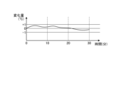
- FIG. 6 is an explanatory diagram showing an example of the prediction result of the amount of change in indoor temperature. Note that FIG. 6 shows an example of a prediction result of the indoor temperature change amount during cooling operation.
- the first prediction unit 21 uses the prediction model to predict the amount of change in indoor temperature of each indoor unit 4 for 30 minutes from the prediction start time.
- FIG. 7 is an explanatory diagram showing an example of the prediction result of thermo ON/OFF time.
- the first prediction unit 21 predicts the indoor temperature for 30 minutes from the prediction start time by adding the indoor temperature detected at the prediction start time to the amount of change in the indoor temperature for 30 minutes from the prediction start time.
- the second prediction unit 22 predicts the thermo ON time and thermo OFF time of each indoor unit 4 using the predicted indoor temperature for 30 minutes and the set temperature which is the target value of the air conditioning operation.
- the thermo-on temperature is +0.5°C of the set temperature
- the thermo-off temperature is -0.5°C of the set temperature.
- the thermo ON temperature is -0.5°C of the set temperature
- the thermo OFF temperature is +0.5°C of the set temperature.
- the thermo-ON temperature is 19.5°C and the thermo-OFF temperature is 20.5°C.
- the second prediction unit 22 uses the predicted indoor temperature for 30 minutes from the prediction start time and the set temperature, which is the target value of the air conditioning operation, to determine whether the indoor temperature exceeds the thermo ON temperature of 27.5°C.
- the time when the thermometer is turned on is predicted as the thermo ON time.
- the second prediction unit 22 predicts, as the thermo-OFF time, the time when the indoor temperature drops below the thermo-OFF temperature of 26.5° C. from the predicted thermo-ON time. In other words, the second prediction unit 22 predicts the thermo ON time and thermo OFF time of each indoor unit 4 for 30 minutes from the prediction start time.
- FIG. 8 is an explanatory diagram showing an example of a variation in power consumption of the compressor 3A1 due to timing adjustment of thermo ON/OFF of each indoor unit 4 in the first embodiment.
- FIG. 8 shows the prediction results of the room temperature of the room where each indoor unit 4 (shown as indoor unit 4A and indoor unit 4B in FIG. 8) is installed for 60 minutes, the prediction result of the thermo ON or thermo OFF timing, and the compressor. The results of predicting the timing of stopping and restarting 3A1 and the detection results of fluctuations in power consumption according to thermo ON/OFF in each indoor unit 4A and 4B are shown.
- the prediction result before ON/OFF timing adjustment is shown, and the right side of the figure shows the prediction result after thermo ON/OFF timing adjustment.
- the detection results of power consumption fluctuations are based on the predicted room temperature and thermo-ON or thermo-OFF timing of the indoor units 4A and 4B when the predicted results are realized using actual machines. Stopping/driving of 3A1 and fluctuations in power consumption at that time are detected.
- the indoor unit 4A has a set temperature of 24°C, a thermo-ON temperature of 24.5°C, and a thermo-OFF temperature of 23.5°C. According to the prediction result of the indoor unit 4A for 60 minutes, first, the thermostat is turned on, and after 10 minutes elapsed, the indoor temperature falls below the thermostat OFF temperature, and the thermostat is turned off. Next, in the indoor unit 4A, the indoor temperature rises to the thermo-ON temperature between 30 and 40 minutes, and the thermostat turns from thermo-off to thermo-on.
- the indoor temperature of the indoor unit 4A again falls below the thermo-off temperature and the thermo-off is turned off, and thereafter the thermo-off is maintained until 60 minutes have elapsed. That is, in the example before timing adjustment shown in FIG. 8, the thermostat is on twice and the thermostat is off twice in 60 minutes.
- the indoor unit 4B has a set temperature of 28°C, a thermo-ON temperature of 28.5°C, and a thermo-OFF temperature of 27.5°C. According to the prediction result of the indoor unit 4B for 60 minutes, when the indoor temperature reaches the thermo ON temperature after 20 minutes elapsed from the state where the thermostat is OFF, the thermostat is turned ON. Next, when the elapsed time is 25 minutes, the indoor temperature of the indoor unit 4B falls below the thermo-off temperature, and the thermo-on switches from the thermo-on to the thermo-off. Next, the indoor unit 4B turns on the thermostat when the indoor temperature reaches the thermostat ON temperature after 50 minutes have elapsed.
- the indoor temperature drops below the thermo-off temperature after 55 minutes have elapsed, and the thermo-off is turned off. That is, in the example before timing adjustment shown in FIG. 8, the thermostat is on twice and the thermostat is off twice in 60 minutes.
- the compressor 3A1 In the outdoor unit 3, when either the indoor units 4A or 4B is in the thermo-on period, the compressor 3A1 is turned on, and if both the indoor units 4A or 4B are in the thermo-off period, the compressor 3A1 is turned off.
- the period during which both indoor units 4A and 4B are thermo-OFF is between 10 and 20 minutes, between 25 and 30 minutes, and between 40 and 50 minutes. It is predicted that the compressor 3A1 will be stopped four times and the compressor 3A1 will be restarted three times during the 60 minutes. As mentioned above, restarting the compressor 3A1 requires a large amount of power consumption, and it is expected that the air conditioning system 1 before timing adjustment will have three chances to restart the compressor 3A1, which will consume a large amount of power. .
- the timing of thermo ON/OFF is adjusted so that the thermo ON periods of a plurality of indoor units 4 overlap, thereby reducing the number of times the compressor 3A1 is stopped and restarted. Reduce the associated power consumption.
- the set temperature of the indoor unit 4B is adjusted so that the thermo ON period of the indoor unit 4A overlaps with the thermo ON period of the indoor unit 4B. Adjust the thermo ON period of indoor unit 4B.
- the timing at which the thermostat of the indoor unit 4B is turned on is determined as shown on the left side of FIG. Faster than predicted results.
- the thermo ON period of the indoor unit 4B overlaps with the thermo ON period of the indoor unit 4A from 0 minutes to 10 minutes, so the number of times the drive of the compressor 3A1 is stopped and restarted is 0 minutes to 30 minutes. It will be once in between.
- the timing at which the indoor unit 4B's thermostat is turned on is made earlier than the prediction result shown on the left side of FIG.
- thermo ON period of the indoor unit 4B overlaps with the thermo ON period of the indoor unit 4A from 35 minutes to 40 minutes, so the number of times the drive of the compressor 3A1 is stopped and restarted is 30 to 60 minutes. It will be once in between. That is, in the example after the timing adjustment shown in FIG. 8, the number of times the compressor 3A1 is restarted is two times in 60 minutes, so power consumption due to the restart of the compressor 3A1 can be reduced. In the air conditioning system 1 after timing adjustment, power consumption can be significantly reduced compared to power consumption before timing adjustment.
- thermo ON/OFF a process for adjusting the timing of thermo ON/OFF so that the thermo ON periods of a plurality of indoor units 4 overlap
- FIG. 9 is an explanatory diagram showing an example of a processing operation when specifying the indoor unit 4 whose thermostat will be turned on first from the predicted start time.
- the explanation will be given assuming that there are three indoor units 4 in cooling operation (denoted in the figure as indoor units 4A, 4B, and 4C).
- the second prediction unit 22 calculates the predicted indoor temperature.
- the thermo ON time and thermo OFF time of each indoor unit 4 are predicted using the and set temperature.
- the control unit 51 acquires the prediction result of the second prediction unit 22.
- the control unit 51 determines whether or not there is an indoor unit 4 whose thermostat is turned on at the prediction start time. If there is no indoor unit 4 that is thermo-ON at the predicted start time, the control unit 51 identifies the indoor unit 4 that is predicted to be thermo-ON first after the predicted start time. In the description here, the control unit 51 specifies the indoor unit 4A in FIG. 9 as the indoor unit 4 that turns on the thermostat first.
- FIG. 10 is an explanatory diagram showing an example of a processing operation when specifying the indoor unit 4 (reference indoor unit) whose thermostat will be turned off last from the predicted start time.
- the control unit 51 determines whether there is another indoor unit 4 that turns on the thermostat within the period until the specified indoor unit 4A turns off the thermostat. . If there is no other indoor unit 4 to turn on the thermostat, the control unit 51 stores the thermostat OFF time of the indoor unit 4A in the thermostat OFF time memory 43.
- the control unit 51 since there are two other indoor units 4 (indoor unit 4B and indoor unit 4C) that turn on the thermostat, the control unit 51 turns on the three indoor units 4 later than indoor unit 4B.
- the indoor unit 4C whose thermostat is finally turned off is defined as the reference indoor unit.
- the control unit 51 specifies the indoor unit 4C whose thermostat is turned off last as the reference indoor unit, and stores the identification number of the specified reference indoor unit in the reference indoor unit memory 44.
- FIG. 11 is an explanatory diagram showing an example of a processing operation when predicting a first change time and a second change time related to a change in the set temperature of another indoor unit 4.
- the control unit 51 specifies the indoor unit 4 whose thermostat is turned on first from the thermo-off time of the reference indoor unit as the indoor unit 4 whose set temperature is to be changed.
- the control unit 51 stores the identification number of the indoor unit 4 whose settings are to be changed in the change target memory 45 .
- the control unit 51 specifies the indoor unit 4A as the indoor unit 4 whose thermostat is turned ON first from the reference indoor unit's thermostat OFF time as the indoor unit 4 whose set temperature is to be changed. become.
- control unit 51 sets t minutes before the reference time, which is the thermo-OFF time of the reference indoor unit, as the first change time, and sets t minutes after the reference time as the second change time.
- the reason for setting the time t minutes before the reference time is to prevent all the indoor units 4 from turning off the thermostat by turning on the thermostat of the indoor unit 4A before the thermostat OFF time of the reference indoor unit.
- the reason for setting the time to be t minutes after the reference time is to ensure the comfort of the user by not allowing the set temperature to remain low (a state in which excessive cooling capacity is exerted) for a long period of time. Note that, for convenience of explanation, the case where the time is t minutes before and after the reference time is shown as an example, but the time may not be the same t minutes before and after the reference time, but may be different times.
- the control unit 51 stores the identification number of the indoor unit 4 whose set temperature is to be changed, the first change time, and the second change time in the change target memory 45.
- the setting unit 52 sets the set temperature of the indoor unit 4A whose set temperature is to be changed to a temperature 1° C. lower than the current temperature at the first change time, and then sets the set temperature at the second change time.
- the set temperature of the indoor unit 4A to be changed is returned to the set temperature before the change. As a result, if the set temperature remains lowered, excessive air conditioning capacity (which the user does not like) will be exerted, so by returning the set temperature to the pre-change temperature, user comfort can be ensured.
- the temperature at which the thermostat is turned on will also be lowered by 1°C, so the room temperature will be lower than the thermostat at the first change time.
- the temperature becomes higher than the temperature at which the indoor unit 4A is turned on, and the indoor unit 4A turns on.
- the thermo-on timing is earlier than the second thermo-on timing of the indoor unit 4A in the prediction results shown in FIG. Since the indoor units 4A are thermo-ON, the initial period in which all the indoor units 4 are thermo-OFF shown in FIG. 9 is eliminated. In the outdoor unit 3, since the thermo ON period of each indoor unit 4 continues, the chances of restarting the compressor 3A1 are reduced.
- FIG. 12 is an explanatory diagram showing an example of the processing operation when setting the next predicted start time.
- the setting unit 52 sets the thermo-OFF time of the indoor unit 4C, which is the reference indoor unit, as the next predicted start time.
- the second prediction unit 22 predicts the indoor temperature of each indoor unit 4 within a prediction period of 30 minutes from the prediction start time, and then predicts the thermo ON time and thermo OFF time of each indoor unit 4.
- the control unit 51 determines, based on the prediction result of the second prediction unit 22, whether there is any indoor unit 4 whose thermostat is turned on at the prediction start time. If there is no indoor unit 4 that is thermo-ON at the predicted start time, the control unit 51 specifies the indoor unit 4 that is predicted to be thermo-ON first from the predicted start time. In this case, the control unit 51 specifies the indoor unit 4B in FIG. 12 as the indoor unit 4 that turns on the thermostat first.
- the control unit 51 determines whether there is another indoor unit 4 whose thermostat is turned on within a period until the thermostat of the identified indoor unit 4B is turned off. judge. If there is no other indoor unit 4 to turn on the thermostat, the control unit 51 stores the thermostat OFF time of the indoor unit 4B in the thermostat OFF time memory 43. In the explanation here, the control unit 51 turns off the thermostat after the indoor unit 4C among the indoor units 4A and 4C that turn on the thermostat because there is another indoor unit 4 that turns on the thermostat in FIG. Let indoor unit 4A be the reference indoor unit.
- the control unit 51 specifies the indoor unit 4 whose thermostat is turned on first from the thermostat OFF time of the reference indoor unit as the indoor unit 4 whose setting is to be changed.
- the setting unit 52 changes the set temperature of the indoor unit 4 whose setting is to be changed, and adjusts the thermo-ON period of the indoor unit 4 whose setting is to be changed so that it overlaps with the thermo-ON period of the reference indoor unit.
- FIG. 12 merely represents the operation up to specifying the reference indoor unit and the indoor unit 4 whose settings are to be changed, and the processing operations of FIGS. 9 to 12 are repeated.
- FIG. 13 is a flowchart showing an example of processing operations of the centralized controller 5 related to control processing. Note that the control process starts at a predicted timing of every 30 minutes.
- the control unit 51 in the control circuit 5C in the centralized controller 5 determines whether there are two or more indoor units 4 that are powered on (step S11). If there are two or more indoor units 4 that are powered on (step S11: Yes), the control unit 51 acquires the prediction result of the second prediction unit 22 in the server device 6 (step S12).
- the prediction result of the second prediction unit 22 is the thermo ON/thermo OFF time of each indoor unit 4 for a prediction period, for example, 30 minutes from the prediction start time.
- the control unit 51 refers to the second prediction result and determines whether there is any indoor unit 4 whose thermostat has been turned on since before the prediction start time (step S13). If there is an indoor unit 4 whose thermostat has been turned on since before the predicted start time (step S13: Yes), the control unit 51 identifies the indoor unit 4 whose thermostat will be turned off last among the indoor units whose thermostat is turned on (step S13: Yes). Step S14).
- the control unit 51 specifies the indoor unit identification number of the indoor unit 4 whose thermostat will be turned off at the end (step S15). Note that the specified indoor unit 4 whose thermostat is turned off at the end becomes the reference indoor unit.
- the control unit 51 stores the specified thermo-OFF time of the indoor unit 4 in the thermo-OFF time memory 43 (step S16). Then, the control unit 51 identifies the indoor unit 4 whose thermostat is turned ON first after the stored thermostat OFF time (step S17), and proceeds to the process of M1 shown in FIG. 14.
- the control unit 51 identifies the indoor unit 4 that will be thermo-on for the first time within the prediction period (step S18).
- the indoor unit 4 that first turns on the thermostat is the indoor unit 4A.
- the control unit 51 determines whether there is another indoor unit 4 that turns on the thermostat during the period until the specified indoor unit 4 that turns on the thermostat first turns off the thermostat (step S19).
- the other indoor units 4 that turn on the thermostat are the indoor unit 4B and the indoor unit 4C.
- step S19: No If there is no other indoor unit 4 whose thermostat is turned on during the period until the specified indoor unit 4 whose thermostat is turned ON first turns its thermostat OFF (step S19: No), the control unit 51 turns the thermostat to The thermo-off time of the indoor unit 4 that is turned on is stored in the thermo-off time memory 43 (step S20). The control unit 51 returns to the process of step S17 in order to specify the indoor unit 4 whose thermostat is turned on first after the stored thermostat OFF time.
- step S19: Yes If there is another indoor unit 4 that turns on the thermostat within the period until the specified indoor unit 4 that turns on the thermostat first turns off the thermostat (step S19: Yes), the control unit 51 controls the other indoor unit 4 to turn on the thermostat (step S19: Yes). Among them, the other indoor unit 4 whose thermostat will be turned off last within the prediction period is identified (step S21). In the example shown in FIG. 9, the indoor unit 4 whose thermostat is finally turned off is the indoor unit 4C. The indoor unit 4 whose thermostat is finally turned off becomes the reference indoor unit.
- the control unit 51 stores the specified thermo-off time of the other indoor unit 4 whose thermostat will be turned off last in the thermo-off time memory 43 (step S22).
- the thermo-off time memory 43 stores the indoor unit identification number and thermo-off time of the indoor unit 4C, which will be the indoor unit 4 that will turn off the thermostat last.
- the control unit 51 returns to the process of step S17 in order to specify the indoor unit 4 whose thermostat is turned on first after the stored thermostat OFF time. In the example shown in FIG. 10, the indoor unit 4 that first turns on the thermostat is the indoor unit 4A. Further, if there are not two or more indoor units 4 that are powered on (step S11: No), the control unit 51 ends the processing operation shown in FIG. 13.
- FIG. 14 is a flowchart showing an example of processing operations of the centralized controller 5 related to control processing. Note that FIG. 14 is a process subsequent to M1 shown in FIG. 13.
- the control unit 51 sets the set temperature of the indoor unit 4, which is specified to be the first thermo ON after the thermo OFF time stored in step S17, for a predetermined time t from the stored thermo OFF time.
- the first change time which is the timing for changing the previous set temperature, is stored in the change target memory 45 (step S31).
- the stored thermo-OFF time is the thermo-OFF time of the indoor unit 4C.
- control unit 51 stores in the change target memory 45 a second change time, which is the timing for returning the set temperature after a predetermined time t minutes from the stored thermostat OFF time (step S32). That is, the change target memory 45 stores the indoor unit identification number of the indoor unit 4 whose set temperature is to be changed, the first change time, and the second change time.
- the control unit 51 acquires the re-prediction result of the second prediction unit 22, which re-predicts the thermo-ON/OFF time of each indoor unit 4 from the stored thermo-OFF time to the prediction period, through the communication network 7 (step S34).
- the prediction period here is a prediction period that starts from the first prediction start time, not the re-prediction start time.
- the control unit 51 notifies the second prediction unit 22 of the new prediction start time.
- the second prediction unit 22 that has received the new prediction start time predicts for 30 minutes from the new prediction start time and notifies the control unit 51 of the prediction.
- the control unit 51 Based on the re-prediction result, the control unit 51 identifies the indoor unit 4 that will turn on the thermostat first after the stored thermostat OFF time (step S35). Note that the stored thermo-OFF time is the thermo-OFF time of the indoor unit 4C in the example of FIG. Furthermore, the indoor unit 4 whose thermostat is turned ON first after the thermostat OFF time is the indoor unit 4B in the example of FIG. 12. The control unit 51 determines whether the specified thermo-ON time of the indoor unit 4 is within the prediction period (step S36).
- Step S36 If the specified thermo ON time of the indoor unit 4 is within the prediction period (Step S36: Yes), the control unit 51 sets the stored thermo OFF time as the next predicted start time (Step S37). Then, the control unit 51 returns to the process of step S12 shown in FIG. 13 in order to obtain the next prediction result from the second prediction unit 22.
- step S36: No If the specified thermo-ON time of the indoor unit 4 is not within the prediction period (step S36: No), the control unit 51 ends the processing operation shown in FIG. 14.
- FIG. 15 is a flowchart showing an example of processing operations of the centralized controller 5 related to setting processing.
- the setting process is a process for the indoor unit 4 (target indoor unit) identified in the process of FIGS. 13 and 14.
- the setting unit 52 in the control circuit 5C in the centralized controller 5 shown in FIG. 15 determines whether the first change time and the second change time exist in the change target memory 45 in the memory 31 (step S41). When the first change time and the second change time of the indoor unit 4 to be changed are present in the change target memory 45 (step S41: Yes), the setting unit 52 sets the set temperature for the indoor unit 4 to be changed. A first change time and a second change time for changing are set (step S42). Then, the setting unit 52 ends the processing operation shown in FIG. 15.
- the indoor unit 4 to be changed for which the first change time and the second change time are respectively set when the set first change time is reached, the current set temperature is changed. Change the set temperature to lower the temperature by -1°C. Then, since the indoor unit 4 to be changed turns on the thermostat according to the changed set temperature, the thermostat ON period is advanced so as to overlap with the thermostat ON period of the reference indoor unit. Then, when the set second change time of the indoor unit 4 to be changed is reached, the set temperature after the change is returned to the original set temperature before the change.
- step S41: No the setting unit 52 ends the processing operation shown in FIG. 15.
- the server device 6 in the air conditioning system 1 of the first embodiment predicts the indoor temperature of an air-conditioned space in which a plurality of indoor units 4 are installed, using a plurality of operating state quantities related to air conditioning operation.
- the server device 6 predicts the thermo-on time and thermo-off time of each indoor unit 4 among the plurality of indoor units 4 using the predicted indoor temperature and the set temperature that is a target value for air conditioning operation.
- the centralized controller 5 uses the predicted thermo ON time and thermo OFF time of each indoor unit 4 to determine the number of stops and restarts of the compressor 3A1 according to the thermo ON time or thermo OFF time of each indoor unit 4. reduce As a result, by suppressing the number of times the compressor 3A1 is stopped and restarted, user comfort can be ensured while suppressing power consumption related to air conditioning operation.
- the control unit 51 uses the prediction result of the second prediction unit 22 to set the set temperature of each indoor unit 4 so that the thermo ON periods of two or more indoor units 4 among the plurality of indoor units 4 overlap. change.
- the control unit 51 uses the prediction result of the second prediction unit 22 to set the set temperature of each indoor unit 4 so that the thermo ON periods of two or more indoor units 4 among the plurality of indoor units 4 overlap. change.
- the number of stops and restarts of the compressor 3A1 is suppressed, and the power consumption related to air conditioning operation is suppressed while providing a comfortable experience for users. can ensure sex.
- the control unit 51 uses the prediction result of the second prediction unit 22 to predict the number of times the compressor 3A1 will be stopped and restarted within a predetermined period, and calculates the number of times the compressor 3A1 will be stopped and restarted within a predetermined period. Identify unit 4 as the reference indoor unit.
- the control unit 51 changes the set temperatures of the other indoor units 4 so that the thermo-ON time of the other indoor units 4 other than the reference indoor unit overlaps with the thermo-ON period of the reference indoor unit. As a result, by making the thermo-on periods of two or more indoor units 4 overlap, the number of stops and restarts of the compressor 3A1 is suppressed, and the power consumption related to air conditioning operation is suppressed while providing a comfortable experience for users. can ensure sex.
- the setting temperature of the indoor unit 4 to be changed is changed in a predetermined temperature unit, for example, in units of 1° C.
- the setting temperature is not limited to this, and can be changed as appropriate.
- the control unit 51 selects the indoor unit 4 that will be the first thermo-ON time among the other indoor units 4 so that the thermo-ON time of the other indoor units 4 other than the reference indoor unit overlaps with the thermo-ON period of the reference indoor unit.
- the case where the indoor unit 4 is the target of setting change is illustrated.
- the number of indoor units 4 to be changed is not limited to one, and can be changed as appropriate.
- the centralized controller 5 in the air conditioning system 1 of the first embodiment obtains the prediction results of the thermo ON time and thermo OFF time of each indoor unit 4 from the control circuit 6C in the server device 6, and based on the prediction results, The case where control processing is executed is illustrated.
- the first prediction unit 21 and the second prediction unit 22 may be provided within the centralized controller 5, and an embodiment thereof will be described below as Example 2.
- FIG. 16 is an explanatory diagram showing an example of the configuration of an air conditioner 1A according to the second embodiment. Note that the same components as those of the air conditioning system 1 of the first embodiment are given the same reference numerals, and descriptions of the overlapping components and operations will be omitted.
- An air conditioner 1A shown in FIG. 16 includes an air conditioner 2 and a central controller 5. It is assumed that there is no server device 6.
- FIG. 17 is a block diagram showing an example of the configuration of the centralized controller 5. As shown in FIG. A storage unit 5B in the centralized controller 5 shown in FIG. 17 has a predictive model memory 11A that stores predictive models. The prediction model includes a thermo-OFF prediction model and a thermo-ON prediction model.
- control circuit 5C includes a first prediction unit 21A and a second prediction unit 22A in addition to the control unit 51 and the setting unit 52.
- the first prediction unit 21A uses a prediction model that uses a plurality of operating state quantities related to air conditioning operation to predict the indoor temperature of the air-conditioned space in which the plurality of indoor units 4 are installed, for example, at a prediction timing of every 30 minutes. Predict each room temperature for 30 minutes from the time point.
- the second prediction unit 22A uses the indoor temperature of each indoor unit 4 predicted by the first prediction unit 21A and the set temperature, which is a target value for air conditioning operation, to determine the thermo-ON time and thermo-OFF time of each indoor unit 4. Predict the time.
- the control unit 51A uses the prediction result of the second prediction unit 22A to stop and restart the compressor 3A1 in the outdoor unit refrigerant circuit 3A according to the thermo ON or thermo OFF time of each indoor unit 4. Decrease the number of times.
- each indoor unit 4 is set so that the period in which the thermostat is ON of two or more indoor units 4 among the plurality of indoor units 4 overlaps. This is achieved by changing the set temperature in predetermined temperature units.
- the control unit 51 uses the prediction result of the second prediction unit 22A to predict, for example, the number of times the compressor 3A1 will be stopped and restarted within a predetermined period of 30 minutes from the prediction start time. Further, the control unit 51 specifies the indoor unit 4 that is predicted to turn off the thermostat last within a predetermined period as the reference indoor unit. Further, the setting unit 52 sets the set temperature of the other indoor units 4 to be changed to a predetermined temperature so that the thermo ON period of the other indoor units 4 other than the reference indoor unit overlaps with the thermo ON period of the reference indoor unit. Change in units.
- the first prediction unit 21A re-predicts the indoor temperature of the indoor space of each indoor unit 4 based on the changed set temperature.
- the second prediction unit 22A then re-sets the thermo-ON time and thermo-OFF time of each indoor unit 4 using the indoor temperature predicted by the first prediction unit 21A and the set temperature which is the target value for air conditioning operation. Predict.
- the control unit 51A controls the indoor unit 4 using the re-prediction result of the second prediction unit 22A.
- FIG. 18 is a flowchart showing an example of processing operations of the centralized controller 5 related to control processing. Note that the control process starts at a predicted timing of every 30 minutes.
- the control unit 51 in the centralized controller 5 determines whether there are two or more indoor units 4 that are powered on (step S11). If there are two or more indoor units 4 that are powered on (Step S11: Yes), the first prediction unit 21A starts prediction at the prediction start time (Step S12A).
- the first prediction unit 21A predicts the amount of change in the indoor temperature of each indoor unit 4 for a prediction period, for example, 30 minutes from the prediction start time (step S12B).
- the second prediction unit 22A predicts the thermo ON/thermo OFF time of each indoor unit 4 for the prediction period from the prediction start time (step S12C).
- the control unit 51 then proceeds to step S13 to determine whether there is any indoor unit 4 whose thermostat is turned on within the prediction period. Note that since the operations after the process in step S13 are the same as the processes after the process in step S13 shown in FIG. 13, a description of the overlapping processes will be omitted.
- the centralized controller 5 of the second embodiment predicts the indoor temperature of an air-conditioned space in which a plurality of indoor units 4 are installed, using a plurality of operating state quantities related to air conditioning operation.
- the centralized controller 5 uses the indoor temperature predicted by the first prediction unit 21A and the set temperature, which is a target value for air conditioning operation, to determine the thermo-on time and thermo-off time of each indoor unit 4 among the plurality of indoor units 4. Predict the time.
- the centralized controller 5 uses the predicted thermo ON time and thermo OFF time of each indoor unit 4 to stop and restart the compressor 3A1 according to the thermo ON time or thermo OFF time of each indoor unit 4. Decrease the number of times. As a result, by suppressing the number of times the compressor 3A1 is stopped and restarted, user comfort can be ensured while suppressing power consumption related to air conditioning operation.
- the setting of the indoor unit 4 is to change the thermo-on period of at least one indoor unit 4 among the plurality of indoor units 4 so that the thermo-on period of the reference indoor unit overlaps with the thermo-on period of the reference indoor unit.
- An example of changing the temperature is given. However, it is not necessary to change the set temperatures of all the indoor units 4, and it is possible to change them as appropriate.
- the components of the illustrated parts do not necessarily need to be physically configured as illustrated.
- the specific form of dispersion/integration of each part is not limited to what is shown in the diagram, but all or part of it may be functionally or physically distributed/integrated in arbitrary units depending on various loads, usage conditions, etc. can be configured.
- processing functions performed in each device can be performed in whole or in part on a CPU (Central Processing Unit) (or a microcomputer such as an MPU (Micro Processing Unit) or an MCU (Micro Controller Unit)). You may also choose to execute it. Further, various processing functions may be executed in whole or in part on a program that is analyzed and executed by a CPU (or a microcomputer such as an MPU or MCU) or on hardware using wired logic. Needless to say.
- a CPU Central Processing Unit
- MPU Micro Processing Unit
- MCU Micro Controller Unit
- Air conditioning system 1A Air conditioner 2 Air conditioner 3 Outdoor unit 3A1 Compressor 4 Indoor unit 5 Centralized controller 5C Control circuit 6 Server device 6C Control circuit 21, 21A First prediction unit 22, 22A Second prediction unit 51 Control section 52 Setting section
Landscapes
- Engineering & Computer Science (AREA)
- Mechanical Engineering (AREA)
- General Engineering & Computer Science (AREA)
- Chemical & Material Sciences (AREA)
- Combustion & Propulsion (AREA)
- Physics & Mathematics (AREA)
- Thermal Sciences (AREA)
- Human Computer Interaction (AREA)
- Signal Processing (AREA)
- Fuzzy Systems (AREA)
- Mathematical Physics (AREA)
- Air Conditioning Control Device (AREA)
Abstract
Description
図1は、実施例1の空気調和システム1の構成の一例を示す説明図である。図1に示す空気調和システム1は、空気調和機2と、集中コントローラ5と、サーバ装置6とを有する。空気調和機2は、1台の室外機3と、N台の室内機4とを有する。集中コントローラ5は、空気調和機2全体を制御する。サーバ装置6は、通信網7を介して集中コントローラ5と通信し、集中コントローラ5を介して空気調和機2に各種サービスを提供する。
図2は、サーバ装置6の構成の一例を示すブロック図である。図2に示すサーバ装置6は、通信部6Aと、記憶部6Bと、制御回路6Cとを有する。通信部6Aは、通信網7を介して集中コントローラ5と通信する。制御回路6Cは、サーバ装置6全体を制御する。記憶部6Bは、各種情報を記憶する。
図3は、予測モデルの特徴量の一例を示す説明図である。サーバ装置6内の予測モデルメモリ11に格納する予測モデルは、サーモOFFの予測モデルと、サーモONの予測モデルとを有する。サーモOFFの予測モデルは、室内機4毎に、サーモOFF時の予測開始時刻から30分間分の室内空間の室内温度の変化量を予測するモデルである。サーモONの予測モデルは、室内機4毎に、サーモON時の予測開始時刻から30分間分の室内空間の室内温度の変化量を予測するモデルである。
図4は、集中コントローラ5の構成の一例を示すブロック図である。図4に示す集中コントローラ5は、通信部5Aと、記憶部5Bと、制御回路5Cとを有する。通信部5Aは、空気調和機2内の室内機4及び室外機3と通信すると共に、通信網7を介してサーバ装置6と通信する。記憶部5Bは、各種情報を記憶し、また、メモリ31を有する。記憶部5Bは、メモリ31を有する。制御回路5Cは、集中コントローラ5全体を制御する。
図5は、メモリ31のメモリ構成の一例を示す説明図である。図5に示すメモリ31は、室内機メモリ41と、サーモON時刻メモリ42と、サーモOFF時刻メモリ43と、基準室内機メモリ44と、変更対象メモリ45とを有する。
図6は、室内温度変化量の予測結果の一例を示す説明図である。尚、図6は、冷房運転時の室内温度変化量の予測結果の一例を示している。第1の予測部21は、予測モデルを用いて、予測開始時刻から各室内機4の30分間分の室内温度の変化量を予測する。
次に、複数の室内機4のサーモON期間が重なるようにサーモON/OFFのタイミングを調整する処理について詳細に説明する。
図16は、実施例2の空気調和装置1Aの構成の一例を示す説明図である。尚、実施例1の空気調和システム1と同一の構成には同一符号を付すことで、その重複する構成及び動作の説明については省略する。図16に示す空気調和装置1Aは、空気調和機2と、集中コントローラ5とを有する。サーバ装置6はないものとする。図17は、集中コントローラ5の構成の一例を示すブロック図である。図17に示す集中コントローラ5内の記憶部5Bは、予測モデルを格納する予測モデルメモリ11Aを有する。予測モデルは、サーモOFFの予測モデルと、サーモONの予測モデルとを有する。
図18は、制御処理に関わる集中コントローラ5の処理動作の一例を示すフローチャートである。尚、制御処理は、30分毎の予測タイミングで開始する。図18において集中コントローラ5内の制御部51は、電源ON中の室内機4が2台以上であるか否かを判定する(ステップS11)。第1の予測部21Aは、電源ON中の室内機4が2台以上の場合(ステップS11:Yes)、予測開始時刻で予測を開始する(ステップS12A)。
1A 空気調和装置
2 空気調和機
3 室外機
3A1 圧縮機
4 室内機
5 集中コントローラ
5C 制御回路
6 サーバ装置
6C 制御回路
21、21A 第1の予測部
22、22A 第2の予測部
51 制御部
52 設定部
Claims (17)
- 圧縮機を備える室外機と、当該室外機に冷媒配管で接続される複数の室内機と、前記室外機及び前記複数の室内機を制御する制御装置と、前記制御装置と通信可能なサーバ装置と、を有する空気調和システムであって、
前記サーバ装置は、
空調運転に関わる複数の運転状態量を用いて、前記複数の室内機が設置された空調空間の室内温度を予測する第1の予測部と、
前記第1の予測部で予測した前記室内温度と前記空調運転の目標値である設定温度とを用いて、前記複数の室内機の内、各室内機がサーモONとなる時点及びサーモOFFとなる時点を予測する第2の予測部と、を有し、
前記制御装置は、
前記第2の予測部の予測結果を用いて、前記各室内機が前記サーモON又は前記サーモOFFとなる時点に応じて前記圧縮機の駆動を制御する制御部を有することを特徴とする空気調和システム。 - 前記制御部は、
前記第2の予測部の予測結果を用いて、前記圧縮機の駆動の停止及び再起動の回数を減少させるように前記圧縮機の駆動を制御することを特徴とする請求項1に記載の空気調和システム。 - 前記制御部は、
前記第2の予測部の予測結果を用いて、前記複数の室内機の内、2台以上の室内機における前記サーモONとなる時点が重なるように、前記各室内機の設定温度を変更することを特徴とする請求項1に記載の空気調和システム。 - 前記制御部は、
前記第2の予測部の予測結果を用いて、所定期間内の前記圧縮機の駆動の停止及び再起動の回数を予測し、前記所定期間内において最後にサーモOFFになると予測される前記室内機を基準室内機として特定し、当該基準室内機以外の他の室内機の前記サーモONとなる時点が前記基準室内機の前記サーモONとなる時点と重なるように、前記他の室内機の設定温度を変更することを特徴とする請求項1に記載の空気調和システム。 - 前記制御部は、
前記室内機の前記設定温度を所定温度単位で変更することを特徴とする請求項4に記載の空気調和システム。 - 前記第1の予測部は、
前記複数の運転状態量の中から予測に使用する運転状態量を選択して回帰分析を行うことで前記室内温度を予測することを特徴とする請求項1~5の何れか一つに記載の空気調和システム。 - 前記予測に使用する前記運転状態量は、少なくとも前記設定温度、前記室内温度及び外気温度を含むことを特徴とする請求項6に記載の空気調和システム。
- 前記第1の予測部は、
前記制御部にて前記室内機の設定温度が変更されると、変更後の設定温度に基づき、前記各室内機の室内空間の室内温度を予測し、
前記第2の予測部は、
前記第1の予測部で予測した前記室内温度と前記空調運転の目標値である設定温度とを用いて、前記各室内機がサーモONとなる時点及びサーモOFFとなる時点を予測し、
前記制御部は、
前記第2の予測部の予測結果を用いて、前記圧縮機の駆動を制御することを特徴とする請求項3~5の何れか一つに記載の空気調和システム。 - 圧縮機を備える室外機と、当該室外機に冷媒配管で接続される複数の室内機と、前記室外機及び前記複数の室内機を制御する制御装置と、を有する空気調和装置であって、
前記制御装置は、
空調運転に関わる複数の運転状態量を用いて、前記複数の室内機が設置された空調空間の室内温度を予測する第1の予測部と、
前記第1の予測部で予測した前記室内温度と前記空調運転の目標値である設定温度とを用いて、前記複数の室内機の内、各室内機がサーモONとなる時点及びサーモOFFとなる時点を予測する第2の予測部と、
前記第2の予測部の予測結果を用いて、前記各室内機が前記サーモON又は前記サーモOFFとなる時点に応じて前記圧縮機の駆動を制御する制御部と、
を有することを特徴する空気調和装置。 - 前記制御部は、
前記第2の予測部の予測結果を用いて、前記圧縮機の駆動の停止及び再起動の回数を減少させるように前記圧縮機の駆動を制御することを特徴とする請求項9に記載の空気調和装置。 - 前記制御部は、
前記第2の予測部の予測結果を用いて、前記複数の室内機の内、2台以上の室内機における前記サーモONとなる時点が重なるように、前記各室内機の設定温度を変更することを特徴とする請求項9に記載の空気調和装置。 - 前記制御部は、
前記第2の予測部の予測結果を用いて、所定期間内の前記圧縮機の駆動の停止及び再起動の回数を予測し、前記所定期間内において最後にサーモOFFになると予測される前記室内機を基準室内機として特定し、当該基準室内機以外の他の室内機の前記サーモONとなる時点が前記基準室内機の前記サーモONとなる時点と重なるように、前記他の室内機の設定温度を変更することを特徴とする請求項9に記載の空気調和装置。 - 前記制御部は、
前記室内機の前記設定温度を所定温度単位で変更することを特徴とする請求項12に記載の空気調和装置。 - 前記第1の予測部は、
前記複数の運転状態量の中から予測に使用する運転状態量を選択して回帰分析を行うことで前記室内温度を予測することを特徴とする請求項9~13の何れか一つに記載の空気調和装置。 - 前記予測に使用する前記運転状態量は、少なくとも前記設定温度、前記室内温度及び外気温度を含むことを特徴とする請求項14に記載の空気調和装置。
- 前記第1の予測部は、
前記制御部にて前記室内機の設定温度が変更されると、変更後の設定温度に基づき、前記各室内機の室内空間の室内温度を予測し、
前記第2の予測部は、
前記第1の予測部で予測した前記室内温度と前記空調運転の目標値である設定温度とを用いて、前記各室内機がサーモONとなる時点及びサーモOFFとなる時点を予測し、
前記制御部は、
前記第2の予測部の予測結果を用いて、前記圧縮機の駆動を制御することを特徴とする請求項11又は12に記載の空気調和装置。 - 圧縮機を備える室外機と、当該室外機に冷媒配管で接続される複数の室内機とを有する空気調和装置が前記圧縮機の駆動を制御する制御方法であって、
空調運転に関わる複数の運転状態量を用いて、前記複数の室内機が設置された空調空間の室内温度を予測するステップと、
予測した前記室内温度と前記空調運転の目標値である設定温度とを用いて、前記複数の室内機の内、各室内機がサーモONとなる時点及びサーモOFFとなる時点を予測するステップと、
予測した前記サーモON及び前記サーモOFFとなる時点を用いて、前記各室内機が前記サーモON又は前記サーモOFFとなる時点に応じて前記圧縮機の駆動を制御するステップと、
を実行することを特徴とする制御方法。
Priority Applications (3)
| Application Number | Priority Date | Filing Date | Title |
|---|---|---|---|
| EP23774484.2A EP4502485A4 (en) | 2022-03-24 | 2023-03-06 | AIR CONDITIONING SYSTEM, AIR CONDITIONING UNIT AND CONTROL METHOD |
| US18/837,701 US20250137679A1 (en) | 2022-03-24 | 2023-03-06 | Air conditioning system, air conditioning apparatus, and control method |
| CN202380023994.6A CN118765363A (zh) | 2022-03-24 | 2023-03-06 | 空调系统、空调装置及控制方法 |
Applications Claiming Priority (2)
| Application Number | Priority Date | Filing Date | Title |
|---|---|---|---|
| JP2022048114A JP7468562B2 (ja) | 2022-03-24 | 2022-03-24 | 空気調和システム、空気調和装置及び制御方法 |
| JP2022-048114 | 2022-03-24 |
Publications (1)
| Publication Number | Publication Date |
|---|---|
| WO2023181885A1 true WO2023181885A1 (ja) | 2023-09-28 |
Family
ID=88100626
Family Applications (1)
| Application Number | Title | Priority Date | Filing Date |
|---|---|---|---|
| PCT/JP2023/008348 Ceased WO2023181885A1 (ja) | 2022-03-24 | 2023-03-06 | 空気調和システム、空気調和装置及び制御方法 |
Country Status (5)
| Country | Link |
|---|---|
| US (1) | US20250137679A1 (ja) |
| EP (1) | EP4502485A4 (ja) |
| JP (1) | JP7468562B2 (ja) |
| CN (1) | CN118765363A (ja) |
| WO (1) | WO2023181885A1 (ja) |
Families Citing this family (2)
| Publication number | Priority date | Publication date | Assignee | Title |
|---|---|---|---|---|
| WO2025104810A1 (ja) * | 2023-11-14 | 2025-05-22 | 三菱電機株式会社 | 散水装置および散水方法 |
| JP7816835B1 (ja) * | 2025-09-22 | 2026-02-18 | 株式会社Social Area Networks | 節電制御を行う方法、プログラム及び節電システム |
Citations (6)
| Publication number | Priority date | Publication date | Assignee | Title |
|---|---|---|---|---|
| JPH02154945A (ja) | 1988-12-07 | 1990-06-14 | Daikin Ind Ltd | 空気調和装置の運転制御装置 |
| JP2013221637A (ja) * | 2012-04-13 | 2013-10-28 | Mitsubishi Electric Corp | 空気調和装置 |
| WO2014013528A1 (ja) * | 2012-07-20 | 2014-01-23 | 三菱電機株式会社 | 空気調和装置 |
| WO2014115247A1 (ja) * | 2013-01-22 | 2014-07-31 | 三菱電機株式会社 | システムコントローラ、設備管理システム、デマンド制御方法及びプログラム |
| JP2020067270A (ja) * | 2018-10-23 | 2020-04-30 | 富士通株式会社 | 空調制御プログラム、空調制御方法および空調制御装置 |
| WO2022044325A1 (ja) * | 2020-08-31 | 2022-03-03 | 三菱電機株式会社 | 換気報知装置および換気報知プログラム |
Family Cites Families (11)
| Publication number | Priority date | Publication date | Assignee | Title |
|---|---|---|---|---|
| JP2013213613A (ja) * | 2012-04-02 | 2013-10-17 | Fujitsu General Ltd | 空気調和機 |
| JP6053201B2 (ja) * | 2013-02-06 | 2016-12-27 | ダイキン工業株式会社 | 冷凍装置 |
| US9784464B2 (en) * | 2013-04-22 | 2017-10-10 | Mitsubishi Electric Corporation | Air-conditioning control system and air-conditioning control method |
| WO2016016913A1 (ja) * | 2014-07-30 | 2016-02-04 | 三菱電機株式会社 | 空気調和装置 |
| JP6807556B2 (ja) * | 2015-10-01 | 2021-01-06 | パナソニックIpマネジメント株式会社 | 空調制御方法、空調制御装置及び空調制御プログラム |
| JP6790246B2 (ja) * | 2017-04-27 | 2020-11-25 | 三菱電機株式会社 | 空調装置、制御装置、空調方法及びプログラム |
| KR102488347B1 (ko) * | 2018-01-10 | 2023-01-13 | 삼성전자주식회사 | 에어 컨디셔닝 시스템에서 에어 컨디셔너를 제어하는 장치 및 방법 |
| WO2020121437A1 (ja) * | 2018-12-12 | 2020-06-18 | 三菱電機株式会社 | 空調制御装置及び空調制御方法 |
| US11067325B2 (en) * | 2019-06-14 | 2021-07-20 | Hitachi-Johnson Controls Air Conditioning, Inc. | Refrigeration cycle optimization |
| JP7512639B2 (ja) * | 2020-03-27 | 2024-07-09 | 株式会社富士通ゼネラル | 空気調和装置 |
| WO2021214888A1 (ja) * | 2020-04-21 | 2021-10-28 | 三菱電機株式会社 | 空気調和機 |
-
2022
- 2022-03-24 JP JP2022048114A patent/JP7468562B2/ja active Active
-
2023
- 2023-03-06 US US18/837,701 patent/US20250137679A1/en active Pending
- 2023-03-06 CN CN202380023994.6A patent/CN118765363A/zh active Pending
- 2023-03-06 EP EP23774484.2A patent/EP4502485A4/en active Pending
- 2023-03-06 WO PCT/JP2023/008348 patent/WO2023181885A1/ja not_active Ceased
Patent Citations (6)
| Publication number | Priority date | Publication date | Assignee | Title |
|---|---|---|---|---|
| JPH02154945A (ja) | 1988-12-07 | 1990-06-14 | Daikin Ind Ltd | 空気調和装置の運転制御装置 |
| JP2013221637A (ja) * | 2012-04-13 | 2013-10-28 | Mitsubishi Electric Corp | 空気調和装置 |
| WO2014013528A1 (ja) * | 2012-07-20 | 2014-01-23 | 三菱電機株式会社 | 空気調和装置 |
| WO2014115247A1 (ja) * | 2013-01-22 | 2014-07-31 | 三菱電機株式会社 | システムコントローラ、設備管理システム、デマンド制御方法及びプログラム |
| JP2020067270A (ja) * | 2018-10-23 | 2020-04-30 | 富士通株式会社 | 空調制御プログラム、空調制御方法および空調制御装置 |
| WO2022044325A1 (ja) * | 2020-08-31 | 2022-03-03 | 三菱電機株式会社 | 換気報知装置および換気報知プログラム |
Non-Patent Citations (1)
| Title |
|---|
| See also references of EP4502485A4 |
Also Published As
| Publication number | Publication date |
|---|---|
| EP4502485A4 (en) | 2026-03-18 |
| JP7468562B2 (ja) | 2024-04-16 |
| CN118765363A (zh) | 2024-10-11 |
| EP4502485A1 (en) | 2025-02-05 |
| JP2023141673A (ja) | 2023-10-05 |
| US20250137679A1 (en) | 2025-05-01 |
Similar Documents
| Publication | Publication Date | Title |
|---|---|---|
| CN104364584B (zh) | Hvac控制系统和方法 | |
| US20050223725A1 (en) | Chiller sound reduction control system and method | |
| KR101235546B1 (ko) | 공기 조화기의 제어방법 | |
| JP2002372279A (ja) | 暖房モードと冷房モードとを有する機器を制御するための方法および装置 | |
| WO2023181885A1 (ja) | 空気調和システム、空気調和装置及び制御方法 | |
| KR102558826B1 (ko) | 공기 조화 시스템 및 제어 방법 | |
| CA3040117C (en) | Operating an hvac system based on predicted indoor air temperature | |
| CA3041319C (en) | Operating an hvac system to reach target temperature efficiently | |
| EP3825629A1 (en) | Control device for air conditioning device, outdoor unit, relay unit, heat source unit, and air conditioning device | |
| KR101995583B1 (ko) | 공기조화기 및 그 제어방법 | |
| JP7601748B2 (ja) | 空調制御装置、空調制御システムおよび空調制御方法 | |
| JP7724687B2 (ja) | 空気調和装置および方法 | |
| JP2011214797A (ja) | 冷凍サイクル装置 | |
| WO2020003373A1 (ja) | 空調管理装置および空調システム | |
| JP5954995B2 (ja) | 空気調和装置 | |
| JP4169590B2 (ja) | 空気調和システム及びその運転方法 | |
| CN116202209B (zh) | 多联式空调器及其控制方法和可读存储介质 | |
| CN109790984A (zh) | 用于空气调节和热水供给的系统 | |
| WO2020240685A1 (ja) | 制御装置、空気環境調整システム、空気環境調整方法、プログラム、及び記録媒体 | |
| CN116399057B (zh) | 压缩机切换方法及多联机空调器 | |
| JPH07248141A (ja) | 空気調和機の制御装置 | |
| CN112032943A (zh) | 空调蓄热控制方法 | |
| JP4527637B2 (ja) | 空気調和システムおよび空気調和システムの運転方法 | |
| CN114484748A (zh) | 无压差旁通阀的空调水系统控制方法及装置 | |
| WO2025210709A1 (ja) | 空気調和機および空気調和システム |
Legal Events
| Date | Code | Title | Description |
|---|---|---|---|
| 121 | Ep: the epo has been informed by wipo that ep was designated in this application |
Ref document number: 23774484 Country of ref document: EP Kind code of ref document: A1 |
|
| WWE | Wipo information: entry into national phase |
Ref document number: 18837701 Country of ref document: US |
|
| WWE | Wipo information: entry into national phase |
Ref document number: 202380023994.6 Country of ref document: CN |
|
| WWE | Wipo information: entry into national phase |
Ref document number: 2023774484 Country of ref document: EP |
|
| NENP | Non-entry into the national phase |
Ref country code: DE |
|
| ENP | Entry into the national phase |
Ref document number: 2023774484 Country of ref document: EP Effective date: 20241024 |
|
| WWP | Wipo information: published in national office |
Ref document number: 18837701 Country of ref document: US |