WO2023182079A1 - 処理装置 - Google Patents
処理装置 Download PDFInfo
- Publication number
- WO2023182079A1 WO2023182079A1 PCT/JP2023/009845 JP2023009845W WO2023182079A1 WO 2023182079 A1 WO2023182079 A1 WO 2023182079A1 JP 2023009845 W JP2023009845 W JP 2023009845W WO 2023182079 A1 WO2023182079 A1 WO 2023182079A1
- Authority
- WO
- WIPO (PCT)
- Prior art keywords
- hydrogen
- gas
- blow
- flow path
- engine
- Prior art date
- Legal status (The legal status is an assumption and is not a legal conclusion. Google has not performed a legal analysis and makes no representation as to the accuracy of the status listed.)
- Ceased
Links
Images
Classifications
-
- C—CHEMISTRY; METALLURGY
- C01—INORGANIC CHEMISTRY
- C01B—NON-METALLIC ELEMENTS; COMPOUNDS THEREOF; METALLOIDS OR COMPOUNDS THEREOF NOT COVERED BY SUBCLASS C01C
- C01B3/00—Hydrogen; Gaseous mixtures containing hydrogen; Separation of hydrogen from mixtures containing it; Purification of hydrogen; Reversible storage of hydrogen
- C01B3/50—Separation of hydrogen or hydrogen-containing gases from gaseous mixtures, e.g. purification
- C01B3/501—Separation of hydrogen or hydrogen-containing gases from gaseous mixtures, e.g. purification by diffusion
- C01B3/503—Separation of hydrogen or hydrogen-containing gases from gaseous mixtures, e.g. purification by diffusion characterised by membranes
- C01B3/505—Membranes containing palladium
-
- F—MECHANICAL ENGINEERING; LIGHTING; HEATING; WEAPONS; BLASTING
- F01—MACHINES OR ENGINES IN GENERAL; ENGINE PLANTS IN GENERAL; STEAM ENGINES
- F01M—LUBRICATING OF MACHINES OR ENGINES IN GENERAL; LUBRICATING INTERNAL COMBUSTION ENGINES; CRANKCASE VENTILATING
- F01M13/00—Crankcase ventilating or breathing
- F01M13/04—Crankcase ventilating or breathing having means for purifying air before leaving crankcase, e.g. removing oil
-
- F—MECHANICAL ENGINEERING; LIGHTING; HEATING; WEAPONS; BLASTING
- F01—MACHINES OR ENGINES IN GENERAL; ENGINE PLANTS IN GENERAL; STEAM ENGINES
- F01M—LUBRICATING OF MACHINES OR ENGINES IN GENERAL; LUBRICATING INTERNAL COMBUSTION ENGINES; CRANKCASE VENTILATING
- F01M13/00—Crankcase ventilating or breathing
- F01M13/02—Crankcase ventilating or breathing by means of additional source of positive or negative pressure
-
- F—MECHANICAL ENGINEERING; LIGHTING; HEATING; WEAPONS; BLASTING
- F01—MACHINES OR ENGINES IN GENERAL; ENGINE PLANTS IN GENERAL; STEAM ENGINES
- F01M—LUBRICATING OF MACHINES OR ENGINES IN GENERAL; LUBRICATING INTERNAL COMBUSTION ENGINES; CRANKCASE VENTILATING
- F01M13/00—Crankcase ventilating or breathing
- F01M13/02—Crankcase ventilating or breathing by means of additional source of positive or negative pressure
- F01M13/021—Crankcase ventilating or breathing by means of additional source of positive or negative pressure of negative pressure
-
- F—MECHANICAL ENGINEERING; LIGHTING; HEATING; WEAPONS; BLASTING
- F01—MACHINES OR ENGINES IN GENERAL; ENGINE PLANTS IN GENERAL; STEAM ENGINES
- F01N—GAS-FLOW SILENCERS OR EXHAUST APPARATUS FOR MACHINES OR ENGINES IN GENERAL; GAS-FLOW SILENCERS OR EXHAUST APPARATUS FOR INTERNAL-COMBUSTION ENGINES
- F01N3/00—Exhaust or silencing apparatus having means for purifying, rendering innocuous, or otherwise treating exhaust
- F01N3/08—Exhaust or silencing apparatus having means for purifying, rendering innocuous, or otherwise treating exhaust for rendering innocuous
-
- F—MECHANICAL ENGINEERING; LIGHTING; HEATING; WEAPONS; BLASTING
- F01—MACHINES OR ENGINES IN GENERAL; ENGINE PLANTS IN GENERAL; STEAM ENGINES
- F01N—GAS-FLOW SILENCERS OR EXHAUST APPARATUS FOR MACHINES OR ENGINES IN GENERAL; GAS-FLOW SILENCERS OR EXHAUST APPARATUS FOR INTERNAL-COMBUSTION ENGINES
- F01N3/00—Exhaust or silencing apparatus having means for purifying, rendering innocuous, or otherwise treating exhaust
- F01N3/08—Exhaust or silencing apparatus having means for purifying, rendering innocuous, or otherwise treating exhaust for rendering innocuous
- F01N3/10—Exhaust or silencing apparatus having means for purifying, rendering innocuous, or otherwise treating exhaust for rendering innocuous by thermal or catalytic conversion of noxious components of exhaust
- F01N3/101—Three-way catalysts
-
- F—MECHANICAL ENGINEERING; LIGHTING; HEATING; WEAPONS; BLASTING
- F02—COMBUSTION ENGINES; HOT-GAS OR COMBUSTION-PRODUCT ENGINE PLANTS
- F02M—SUPPLYING COMBUSTION ENGINES IN GENERAL WITH COMBUSTIBLE MIXTURES OR CONSTITUENTS THEREOF
- F02M21/00—Apparatus for supplying engines with non-liquid fuels, e.g. gaseous fuels stored in liquid form
- F02M21/02—Apparatus for supplying engines with non-liquid fuels, e.g. gaseous fuels stored in liquid form for gaseous fuels
- F02M21/0203—Apparatus for supplying engines with non-liquid fuels, e.g. gaseous fuels stored in liquid form for gaseous fuels characterised by the type of gaseous fuel
- F02M21/0206—Non-hydrocarbon fuels, e.g. hydrogen, ammonia or carbon monoxide
-
- F—MECHANICAL ENGINEERING; LIGHTING; HEATING; WEAPONS; BLASTING
- F01—MACHINES OR ENGINES IN GENERAL; ENGINE PLANTS IN GENERAL; STEAM ENGINES
- F01M—LUBRICATING OF MACHINES OR ENGINES IN GENERAL; LUBRICATING INTERNAL COMBUSTION ENGINES; CRANKCASE VENTILATING
- F01M13/00—Crankcase ventilating or breathing
- F01M13/04—Crankcase ventilating or breathing having means for purifying air before leaving crankcase, e.g. removing oil
- F01M2013/0438—Crankcase ventilating or breathing having means for purifying air before leaving crankcase, e.g. removing oil with a filter
-
- F—MECHANICAL ENGINEERING; LIGHTING; HEATING; WEAPONS; BLASTING
- F01—MACHINES OR ENGINES IN GENERAL; ENGINE PLANTS IN GENERAL; STEAM ENGINES
- F01M—LUBRICATING OF MACHINES OR ENGINES IN GENERAL; LUBRICATING INTERNAL COMBUSTION ENGINES; CRANKCASE VENTILATING
- F01M2250/00—Measuring
- F01M2250/60—Operating parameters
-
- F—MECHANICAL ENGINEERING; LIGHTING; HEATING; WEAPONS; BLASTING
- F02—COMBUSTION ENGINES; HOT-GAS OR COMBUSTION-PRODUCT ENGINE PLANTS
- F02M—SUPPLYING COMBUSTION ENGINES IN GENERAL WITH COMBUSTIBLE MIXTURES OR CONSTITUENTS THEREOF
- F02M25/00—Engine-pertinent apparatus for adding non-fuel substances or small quantities of secondary fuel to combustion-air, main fuel or fuel-air mixture
- F02M25/10—Engine-pertinent apparatus for adding non-fuel substances or small quantities of secondary fuel to combustion-air, main fuel or fuel-air mixture adding acetylene, non-waterborne hydrogen, non-airborne oxygen, or ozone
- F02M25/12—Engine-pertinent apparatus for adding non-fuel substances or small quantities of secondary fuel to combustion-air, main fuel or fuel-air mixture adding acetylene, non-waterborne hydrogen, non-airborne oxygen, or ozone the apparatus having means for generating such gases
Definitions
- the present disclosure relates to a processing device.
- Patent Document 1 describes an engine that can be operated with fuel containing hydrogen gas.
- a ventilation port is formed in the crankcase, and a ventilation flow path is provided in the ventilation port.
- a ventilation fan is provided in the ventilation flow path, which forcibly exhausts the gas inside the crankcase to the outside.
- blowby gas containing hydrogen By the way, if blowby gas containing hydrogen is simply returned to the intake air of the engine, the risk of ignition within the intake air increases. Further, if blowby gas containing hydrogen is released to the atmosphere, the blowby gas may remain in a part of the structure (for example, a vehicle) in which the engine is mounted, which may similarly increase the risk of ignition. Patent Document 1 does not consider the treatment of blow-by gas to reduce such ignition risk.
- an object of the present disclosure is to provide a processing device that can reduce the risk of ignition of blow-by gas of a hydrogen engine.
- a processing device is a processing device for processing blow-by gas from a hydrogen engine, and is installed in an exhaust flow path for distributing exhaust gas from the hydrogen engine, and is installed in an exhaust flow path for distributing exhaust gas from the hydrogen engine to remove nitrogen oxides contained in the exhaust gas.
- a scavenging pump for distributing the gas and a treated gas, which is the blowby gas after removing hydrogen, are installed by separating the hydrogen contained in the blow-by gas, which is installed downstream of the scavenging pump in the scavenging flow path. and a hydrogen gas addition section for adding the hydrogen gas produced in the hydrogen separation filter to the catalyst section.
- a pump is provided in the scavenging flow path through which blow-by gas from the hydrogen engine flows. Therefore, by driving this pump, it is possible to actively scavenge blow-by gas containing hydrogen from the hydrogen engine.
- a hydrogen separation filter is provided downstream of the pump in the scavenging flow path to separate hydrogen from the blow-by gas to produce hydrogen gas and treated gas. Hydrogen gas among the gases generated from the blow-by gas is added to the catalyst section, used to reduce nitrogen oxides, and consumed. Therefore, among the gases generated from the blow-by gas, the gas that is recirculated into the intake air of the hydrogen engine or released to the atmosphere becomes treated gas with a relatively low hydrogen concentration. Therefore, the risk of ignition is reduced. Further, since the hydrogen gas generated from the blow-by gas is added to the catalyst section and reused, it is possible to reduce the amount of hydrogen that is separately added to the catalyst section.
- the scavenging flow path may include a reflux section for refluxing the treated gas generated in the hydrogen separation filter to the intake flow path of the hydrogen engine. In this case, it becomes possible to return the treated gas of the blow-by gas to the intake side of the hydrogen engine.
- the processing device includes a first measurement unit for measuring the hydrogen concentration of blow-by gas in a hydrogen engine, a second measurement unit for measuring the hydrogen concentration of the treated gas, and a first measurement unit and a second measurement unit for measuring the hydrogen concentration of the treated gas. a control unit that controls each part based on the measurement results of the second measurement unit; If the hydrogen concentration of the treated gas is equal to or higher than the first threshold, which is lower than the hydrogen concentration, based on the first process of increasing the amount of blow-by gas scavenged by the scavenging pump and the measurement results of the second measurement unit, the hydrogen concentration of the treated gas is determined to be the lower limit of hydrogen.
- the concentration is at least a second threshold value that is lower than the flammable limit concentration
- a second process may be performed to increase the amount of hydrogen separated from the blow-by gas by the hydrogen separation filter.
- the risk of blow-by gas igniting can be reduced more reliably.
- the first threshold value and the second threshold value may be the same value, or may be different values such that the second threshold value is lower (or higher) than the first threshold value.
- the hydrogen concentration of blow-by gas in a hydrogen engine means the hydrogen concentration in a location (for example, inside a crankcase) where blow-by gas can be mixed in a hydrogen engine.
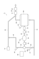
- FIG. 1 is a schematic diagram showing a processing device according to an embodiment.
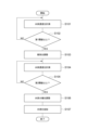
- FIG. 2 is a flowchart showing the operation of the processing device shown in FIG.
- FIG. 1 is a schematic diagram showing a processing device according to an embodiment.
- a processing device 1 shown in FIG. 1 is installed in a large vehicle such as a bus or a truck, or an industrial vehicle, and is used to process exhaust gas G0 and blow-by gas G1 generated in an engine 100.
- Engine 100 is an internal combustion engine (hydrogen engine) driven by fuel containing hydrogen.
- the vehicle in which the processing device 1 is mounted may be, for example, a so-called series type hybrid vehicle that uses the engine 100 as a power source for power generation. In that case, engine 100 may be configured to be driven when the remaining capacity of the battery decreases.
- the engine 100 is, for example, a reciprocating engine, and includes a crankcase that houses a crankshaft, a cylinder that houses a piston that drives the crankshaft, a cylinder head, and the like.
- a combustion chamber in which fuel containing hydrogen is combusted is formed within the cylinder, and blow-by gas G1 containing hydrogen leaked from the combustion chamber is retained in the crankcase, cylinder head, and the like.
- Connected to the engine 100 are an intake flow path 10 for circulating air to the combustion chamber, and an exhaust flow path 20 for circulating exhaust gas G0 from the combustion chamber.
- the processing device 1 includes a catalyst section 21 and an after-treatment section 22 provided in an exhaust flow path 20.
- the catalyst section 21 is an H2-SCR (Selective Catalytic Reduction) device for selectively reducing nitrogen oxides contained in the exhaust gas G0 using hydrogen as a reducing agent.
- the after-treatment section 22 is provided on the downstream side of the catalyst section 21, and is provided with another catalyst section (for example, a urea SCR) that selectively reduces nitrogen oxides contained in the exhaust gas G0 using ammonia or the like as a reducing agent. equipment), filters to collect particulate matter (PM) contained in exhaust gas G0, and oxidize hydrocarbons (HC) and carbon monoxide (CO) contained in exhaust gas G0. and cleaning equipment.
- PM particulate matter
- HC hydrocarbons
- CO carbon monoxide
- the processing device 1 has a scavenging flow path 30 for circulating the blow-by gas G1 of the engine 100.
- the processing device 1 also includes a scavenging pump 31 provided in the scavenging channel 30, a hydrogen separation filter 32, a filter 33, a tank 34, a boost pump 35, and a hydrogen concentration meter 36.
- the scavenging flow path 30 is connected to any part of the engine 100 that should scavenge the blow-by gas G1 (for example, the crankcase, cylinder head, etc.).
- the scavenging pump 31 is for scavenging the blow-by gas G1 from the engine 100 and causing it to flow through the scavenging flow path 30.
- the hydrogen separation filter 32 is provided downstream of the scavenging pump 31 in the scavenging flow path 30.
- the hydrogen separation filter 32 separates hydrogen contained in the blow-by gas G1 to generate hydrogen gas G2 from the blow-by gas G1 and treated gas G3, which is the blow-by gas from which hydrogen has been removed. More specifically, the hydrogen separation filter 32 uses palladium, for example, to separate the blow-by gas G1 into high-purity hydrogen gas (hydrogen gas G2) and non-hydrogen gas (treated gas G3).
- a method is assumed in which high-purity hydrogen is extracted by a hydrogen permeation mechanism using a palladium membrane.
- the filter 33 is provided upstream of the scavenging pump 31 in the scavenging flow path 30.
- the filter 33 removes oil and condensed water contained in the blow-by gas G1.
- the tank 34 is provided between the scavenging pump 31 and the hydrogen separation filter 32 in the scavenging flow path 30.
- the tank 34 can store the blow-by gas G1 led out from the engine 100 to the scavenging passage 30 by driving the scavenging pump 31.
- the boost pump 35 is provided between the tank 34 and the hydrogen separation filter 32 in the scavenging flow path 30.
- the boost pump 35 has a pressure (intake pressure) for returning the blow-by gas G1 (treated gas G3) to the intake flow path 10 as described later, and a pressure higher than the injection pressure of hydrogen gas to the catalyst section 21 as described later. As such, pressure is applied to the blow-by gas G1.
- the hydrogen concentration meter 36 is provided in the tank 34 and measures the hydrogen concentration of the blow-by gas G1 in the tank 34 (that is, at the front stage of the hydrogen separation filter 32).
- the scavenging flow path 30 is connected to the intake flow path 10 on the downstream side of the hydrogen separation filter 32. Therefore, in the processing device 1, it is possible to circulate the processed gas G3 generated from the blow-by gas G1 in the hydrogen separation filter 32 to the intake flow path 10.
- the scavenging flow path 30 includes a reflux section 30p for refluxing the treated gas G3 to the intake flow path 10, as a portion downstream of the hydrogen separation filter 32.
- the processing apparatus 1 includes a hydrogen concentration meter (second measuring section) 37 provided in the reflux section 30p. The hydrogen concentration meter 37 measures the hydrogen concentration of the treated gas G3.
- the processing device 1 includes a hydrogen gas flow path 40 connected to the scavenging flow path 30 via a hydrogen separation filter 32, and a hydrogen supply path 50 for supplying (adding) hydrogen to the catalyst section 21. ing.
- the hydrogen gas flow path 40 is connected to the hydrogen separation filter 32 at one end, and connected to the hydrogen supply path 50 at the other end. Thereby, in the processing apparatus 1, it is possible to introduce the hydrogen gas G2 generated from the blow-by gas G1 in the hydrogen separation filter 32 into the hydrogen supply path 50 through the hydrogen gas flow path 40.
- the hydrogen supply path 50 is connected to the hydrogen supply section 51 at one end, and connected to the stage before the catalyst section 21 of the exhaust flow path 20 at the other end.
- hydrogen supplied from the hydrogen supply section 51 and hydrogen gas G2 introduced from the hydrogen separation filter 32 through the hydrogen gas flow path 40 are supplied to the catalyst section 21 through the hydrogen supply path 50 ( addition). That is, the hydrogen gas flow path 40 and the hydrogen supply path 50 constitute a hydrogen gas addition section 45 for supplying the hydrogen gas G2 generated in the hydrogen separation filter 32 to the catalyst section 21 and adding hydrogen to the catalyst section 21. are doing.
- the processing apparatus 1 includes a hydrogen concentration meter 41 provided in a hydrogen gas flow path 40.
- the hydrogen concentration meter 41 measures the hydrogen concentration of the hydrogen gas G2.
- the processing device 1 includes a hydrogen concentration meter (first measuring section) 101 provided in the engine 100.
- Hydrogen concentration meter 101 measures the hydrogen concentration of blow-by gas G1 in engine 100.
- the hydrogen concentration meter 101 measures the hydrogen concentration of the blow-by gas G1 inside the engine 100, such as the crankcase and cylinder head.
- the hydrogen concentration meter 101 is provided in at least one of the crankcase and the cylinder head and can measure the hydrogen concentration of the blow-by gas G1 in the one. Moreover, the hydrogen concentration meter 101 may be provided in another part of the engine 100 so as to measure the hydrogen concentration of the blow-by gas G1 in the other part.
- Some of the hydrogen concentration meters 36, 37, 41, and 101 described above are omitted because they are configured to estimate (calculate) another part of the measurement results by calculation based on the measurement results of some of them. obtain.
- the hydrogen concentration of the hydrogen gas G2 is calculated based on the measurement result of the hydrogen concentration of the blow-by gas G1 in the engine 100 by the hydrogen concentration meter 101 and the measurement result of the hydrogen concentration of the treated gas G3 by the hydrogen concentration meter 37.
- the hydrogen concentration meter 41 for measuring the hydrogen concentration of the hydrogen gas G2 can be omitted.
- the processing device 1 includes a control section 60.
- the control section 60 acquires information indicating the measurement results of hydrogen concentration from the hydrogen concentration meters 36, 37, 41, and 101, and controls each section of the processing device 1 based on the information.
- the control unit 60 is physically configured as a computer system including a CPU (Central Processing Unit), a RAM (Random Access Memory) which is a main storage device, a ROM (Read Only Memory), a communication module which is a data transmission/reception device, etc. can be done.
- Each process of the control unit 60 is realized by loading a predetermined program onto the above-mentioned hardware, operating the communication module, and reading and writing data in the RAM etc. under the control of the CPU. can be done.
- FIG. 2 is a flowchart showing the operation of the processing device shown in FIG.
- the hydrogen concentration of the blow-by gas G1 in the engine 100 is measured (step S101).
- the hydrogen concentration of the blow-by gas G1 in the engine 100 means the hydrogen concentration at a location in the engine 100 where the blow-by gas G1 can be mixed, and one example is the hydrogen concentration in the crankcase of the engine 100.
- the hydrogen concentration meter 101 measures the hydrogen concentration in the crankcase of the engine 100, and provides the control unit 60 with information indicating the measurement result.
- the control unit 60 determines whether the hydrogen concentration of the blow-by gas G1 in the engine 100 measured in step S101 is greater than or equal to the first threshold (step S102).
- the first threshold value is a value lower than the lower flammable concentration limit of hydrogen in air (for example, 4%), and may be set to about 2%, for example.
- step S102 If the result of the determination in step S102 is a result indicating that the hydrogen concentration of the blow-by gas G1 in the engine 100 is less than the first threshold value (step S102: No), the operation of the processing device 1 returns to step S101, Perform the following steps again.
- step S102 determines whether the hydrogen concentration of the blow-by gas G1 in the engine 100 is equal to or higher than the first threshold value. If the result of the determination in step S102 is a result indicating that the hydrogen concentration of the blow-by gas G1 in the engine 100 is equal to or higher than the first threshold value (step S102: Yes), the control unit 60 controls the scavenging pump 31 to The scavenging amount of the blow-by gas G1 is adjusted to increase, and the scavenging at the hydrogen concentration measurement point of the engine 100 is activated (step S103).
- step S103 if the hydrogen concentration of the blow-by gas G1 in the engine 100 is equal to or higher than the first threshold value, which is lower than the lower limit flammable limit concentration of hydrogen, based on the measurement result of the hydrogen concentration meter 101, the control unit 60 A first process of increasing the amount of blow-by gas G1 scavenged by the scavenging pump 31 is executed.
- the blow-by gas G1 scavenged by the scavenging pump 31 is returned to the intake channel 10 via the scavenging channel 30 and the hydrogen separation filter 32 (as treated gas G3). At that time, the blow-by gas G1 may be at least temporarily and partially stored in the tank 34.
- the hydrogen concentration of the processed gas G3 that is returned to the intake flow path 10 is measured (step S104). This is to ensure that the hydrogen concentration in the intake flow path 10 is outside the flammable range of hydrogen.
- the hydrogen concentration meter 37 measures the hydrogen concentration of the treated gas G3 in the reflux section 30p of the scavenging flow path 30, and provides information indicating the measurement result to the control section 60.
- the control unit 60 determines whether the hydrogen concentration of the processed gas G3 measured in step S104 is equal to or higher than the second threshold (step S105).
- the second threshold value is a value lower than the lower flammable concentration limit of hydrogen in air (for example, 4%), and may be set to about 2%, for example. Note that the first threshold value and the second threshold value may be the same value, or may be different values such that the second threshold value is lower (or higher) than the first threshold value.
- step S105 If the result of the determination in step S105 is a result indicating that the hydrogen concentration of the treated gas G3 is less than the second threshold (step S105: No), the operation of the processing device 1 returns to step S104, and the subsequent steps Perform the process again.
- step S105 determines whether the hydrogen concentration of the treated gas G3 is equal to or higher than the second threshold value.
- the control unit 60 controls the hydrogen concentration in the hydrogen separation filter 32.
- the amount of separation is adjusted to increase (step S106). That is, in step S106, the control unit 60 performs hydrogen separation if the hydrogen concentration of the treated gas G3 is equal to or higher than the second threshold lower than the lower limit flammable limit concentration of hydrogen, based on the measurement result of the hydrogen concentration meter 37.
- a second process is executed to increase the amount of hydrogen separated from the blow-by gas G1 by the filter 32.
- An example of a method for adjusting the amount of hydrogen separated in the hydrogen separation filter 32 is the following method. That is, for example, when the hydrogen separation filter 32 uses a palladium membrane as described above, the hydrogen permeation amount J (NL/min ⁇ cm 2 ) in the hydrogen separation filter 32 is ⁇ (P in 1/2 - P out 1/2 ) ( ⁇ is the hydrogen permeation rate, P in is the hydrogen partial pressure on the source gas side, and P out is the hydrogen partial pressure on the permeated gas side). Therefore, by controlling the boost pump 35 on the inlet side of the hydrogen separation filter 32 to control P in , the control unit 60 can adjust the hydrogen permeation amount J (that is, the amount of hydrogen separation).
- the flow rate of the blow-by gas G1 caused by the scavenging of the scavenging pump 31 and the flow rate of the blow-by gas G1 to be introduced into the hydrogen separation filter 32 in order to realize the desired P in may be different. Therefore, in order to be able to adjust the flow rate of the blow-by gas G1 to the hydrogen separation filter 32 (for use on demand), the tank 34 is used.
- the processing device 1 adds the hydrogen separated by the hydrogen separation filter 32 to the catalyst section 21 (step S107). That is, in the processing device 1, hydrogen gas G2 generated in the hydrogen separation filter 32 is supplied to the catalyst section 21 via the hydrogen gas flow path 40 and the hydrogen supply path 50 (hydrogen gas addition section 45). Note that the hydrogen gas G2 can be constantly supplied to the catalyst section 21 via the hydrogen gas addition section 45 while the hydrogen gas G2 is being generated by the hydrogen separation filter 32.
- the scavenging pump 31 is provided in the scavenging flow path 30 through which the blow-by gas G1 from the engine 100 flows. Therefore, by driving this scavenging pump 31, it is possible to actively scavenge the blow-by gas G1 containing hydrogen from the engine 100.
- a hydrogen separation filter 32 is provided downstream of the scavenging pump 31 in the scavenging flow path 30 to separate hydrogen from the blow-by gas G1 to generate hydrogen gas G2 and treated gas G3.
- Hydrogen gas G2 of the gas generated from the blow-by gas G1 is added to the catalyst section 21, used for reducing nitrogen oxides, and consumed.
- the gas that is recirculated to the intake air of the engine 100 or released to the atmosphere becomes the treated gas G3 having a relatively low hydrogen concentration. Therefore, the risk of ignition is reduced. Further, since the hydrogen gas G2 generated from the blow-by gas G1 is added to the catalyst section 21 and reused, it is possible to reduce the amount of hydrogen that is separately added to the catalyst section 21.
- the scavenging flow path 30 includes a reflux section 30p for refluxing the treated gas G3 generated in the hydrogen separation filter 32 to the intake flow path 10 of the engine 100. Therefore, it becomes possible to return the treated gas G3 of the blow-by gas G1 to the intake side of the engine 100.
- the processing device 1 includes a hydrogen concentration meter 101 for measuring the hydrogen concentration of the blow-by gas G1 in the engine 100, a hydrogen concentration meter 37 for measuring the hydrogen concentration of the treated gas G3, a hydrogen concentration meter 101,
- the control unit 60 controls each unit based on the measurement results of 37. If the hydrogen concentration of the blow-by gas G1 in the engine 100 is equal to or higher than a first threshold lower than the lower flammable limit concentration of hydrogen, based on the measurement result of the hydrogen concentration meter 101, the control unit 60 controls the blow-by gas by the scavenging pump 31.
- the control unit 60 is based on the measurement result of the hydrogen concentration of the blow-by gas G1 in the engine 100 by the hydrogen concentration meter 101 and the measurement result of the hydrogen concentration of the treated gas G3 by the hydrogen concentration meter 37. Then, a first process and a second process for controlling the scavenging pump 31 and the hydrogen separation filter 32 were executed. However, the control unit 60 performs the first process and the second process by calculating and estimating the hydrogen concentration of the blow-by gas G1 and the hydrogen concentration of the treated gas G3 in the engine 100 from the measurement results of other hydrogen concentration meters. May be executed.
- the supply of hydrogen gas G2 to the catalyst section 21 via the hydrogen gas addition section 45 is always performed while the hydrogen gas G2 is being generated by the hydrogen separation filter 32. It is assumed that this is possible.
- a valve or the like is provided in the reflux section 30p, and the control section 60 controls opening and closing of the valve according to the hydrogen concentration of the treated gas G3, so that, for example, the hydrogen concentration of the treated gas G3 is It is also possible to perform a process such that the processed gas G3 is not returned to the intake flow path 10 when the value is equal to or greater than two thresholds.
- a processing device capable of reducing the risk of ignition of blow-by gas of a hydrogen engine is provided.
- SYMBOLS 1 Processing device, 10... Intake flow path, 20... Exhaust flow path, 21... Catalyst part, 30... Scavenging flow path, 30p... Reflux part, 31... Scavenging pump, 32... Hydrogen separation filter, 45... Hydrogen gas addition part , 60... Control unit, 100... Engine (hydrogen engine), G0... Exhaust gas, G1... Blowby gas, G2... Hydrogen gas, G3... Treated gas.
Landscapes
- Engineering & Computer Science (AREA)
- Chemical & Material Sciences (AREA)
- General Engineering & Computer Science (AREA)
- Mechanical Engineering (AREA)
- Combustion & Propulsion (AREA)
- Chemical Kinetics & Catalysis (AREA)
- Organic Chemistry (AREA)
- Toxicology (AREA)
- Health & Medical Sciences (AREA)
- Materials Engineering (AREA)
- Inorganic Chemistry (AREA)
- General Chemical & Material Sciences (AREA)
- Oil, Petroleum & Natural Gas (AREA)
- Lubrication Details And Ventilation Of Internal Combustion Engines (AREA)
- Hydrogen, Water And Hydrids (AREA)
- Exhaust Gas After Treatment (AREA)
Abstract
Description
Claims (3)
- 水素エンジンのブローバイガスを処理するための処理装置であって、
前記水素エンジンからの排気ガスを流通させるための排気流路に設けられ、前記排気ガスに含まれる窒素酸化物を、水素を還元剤として還元するための触媒部と、
前記水素エンジンの前記ブローバイガスを流通させるための掃気流路と、
前記掃気流路に設けられ、前記水素エンジンから前記ブローバイガスを掃気して前記掃気流路に流通させるための掃気ポンプと、
前記掃気流路における前記掃気ポンプの下流側に設けられ、前記ブローバイガスに含まれる水素を分離することにより、前記ブローバイガスから水素ガスと水素除去後のブローバイガスである処理済みガスとを生成するための水素分離フィルタと、
前記水素分離フィルタにおいて生成された前記水素ガスを前記触媒部に添加するための水素ガス添加部と、
を備える処理装置。 - 前記掃気流路は、前記水素分離フィルタにおいて生成された前記処理済みガスを前記水素エンジンの吸気流路に還流するための還流部を含む、
請求項1に記載の処理装置。 - 前記水素エンジンにおける前記ブローバイガスの水素濃度を計測するための第1計測部と、
前記処理済みガスの水素濃度を計測するための第2計測部と、
前記第1計測部及び前記第2計測部の計測結果に基づいて各部の制御を行う制御部と、
を備え、
前記制御部は、
前記第1計測部の計測結果に基づいて、前記水素エンジンにおける前記ブローバイガスの水素濃度が水素の下限可燃限界濃度よりも低い第1閾値以上であった場合、前記掃気ポンプによる前記ブローバイガスの掃気量を増大させる第1処理と、
前記第2計測部の計測結果に基づいて、前記処理済みガスの水素濃度が水素の下限可燃限界濃度よりも低い第2閾値以上であった場合、前記水素分離フィルタによる前記ブローバイガスからの水素の分離量を増大させる第2処理と、
を実行する、
請求項1又は2に記載の処理装置。
Priority Applications (3)
| Application Number | Priority Date | Filing Date | Title |
|---|---|---|---|
| US18/845,010 US20250179951A1 (en) | 2022-03-25 | 2023-03-14 | Treatment device |
| EP23774676.3A EP4502348A4 (en) | 2022-03-25 | 2023-03-14 | TREATMENT DEVICE |
| CN202380027153.2A CN118829781A (zh) | 2022-03-25 | 2023-03-14 | 处理装置 |
Applications Claiming Priority (2)
| Application Number | Priority Date | Filing Date | Title |
|---|---|---|---|
| JP2022-049956 | 2022-03-25 | ||
| JP2022049956A JP7717655B2 (ja) | 2022-03-25 | 2022-03-25 | 処理装置 |
Publications (1)
| Publication Number | Publication Date |
|---|---|
| WO2023182079A1 true WO2023182079A1 (ja) | 2023-09-28 |
Family
ID=88101458
Family Applications (1)
| Application Number | Title | Priority Date | Filing Date |
|---|---|---|---|
| PCT/JP2023/009845 Ceased WO2023182079A1 (ja) | 2022-03-25 | 2023-03-14 | 処理装置 |
Country Status (5)
| Country | Link |
|---|---|
| US (1) | US20250179951A1 (ja) |
| EP (1) | EP4502348A4 (ja) |
| JP (1) | JP7717655B2 (ja) |
| CN (1) | CN118829781A (ja) |
| WO (1) | WO2023182079A1 (ja) |
Families Citing this family (2)
| Publication number | Priority date | Publication date | Assignee | Title |
|---|---|---|---|---|
| CN119467125B (zh) * | 2024-11-26 | 2025-12-05 | 中国第一汽车股份有限公司 | 氢气发动机和车辆 |
| CN119467052A (zh) * | 2024-11-26 | 2025-02-18 | 中国第一汽车股份有限公司 | 油气分离器、氢气发动机和车辆 |
Citations (6)
| Publication number | Priority date | Publication date | Assignee | Title |
|---|---|---|---|---|
| JPH0286915A (ja) * | 1988-09-22 | 1990-03-27 | Toyota Autom Loom Works Ltd | 水素エンジンの排ガス浄化装置 |
| JP2007138799A (ja) * | 2005-11-17 | 2007-06-07 | Toyota Motor Corp | 水素利用内燃機関 |
| JP2007303321A (ja) * | 2006-05-10 | 2007-11-22 | Suzuki Motor Corp | 水素エンジンの排気ガス浄化システム |
| JP2008008247A (ja) * | 2006-06-30 | 2008-01-17 | Toyota Motor Corp | 作動ガス循環型水素エンジン |
| US20170211516A1 (en) * | 2016-01-27 | 2017-07-27 | Serge V. Monros | On-demand oxy-hydrogen fuel system |
| JP2021127704A (ja) | 2020-02-12 | 2021-09-02 | 川崎重工業株式会社 | 4ストロークエンジン及びクランクケースの内部における着火防止方法 |
Family Cites Families (10)
| Publication number | Priority date | Publication date | Assignee | Title |
|---|---|---|---|---|
| US5272871A (en) * | 1991-05-24 | 1993-12-28 | Kabushiki Kaisha Toyota Chuo Kenkyusho | Method and apparatus for reducing nitrogen oxides from internal combustion engine |
| US5937837A (en) * | 1997-12-09 | 1999-08-17 | Caterpillar Inc. | Crankcase blowby disposal system |
| US20100089341A1 (en) * | 2006-01-12 | 2010-04-15 | James Richardson | Hydrogen Reactor and Injection System for Augmenting Crankcase Ventilation in an Internal Combustion Engine |
| JP2009079540A (ja) | 2007-09-26 | 2009-04-16 | Mitsubishi Heavy Ind Ltd | 排ガス浄化システムおよび排ガス浄化方法 |
| JP2010203335A (ja) | 2009-03-04 | 2010-09-16 | Nissan Motor Co Ltd | 排気浄化装置 |
| CN106438039B (zh) * | 2016-09-19 | 2018-11-13 | 石家庄新华能源环保科技股份有限公司 | 一种氢燃料发动机保护系统 |
| WO2019119062A1 (en) * | 2017-12-22 | 2019-06-27 | HYDI IP Pty Ltd | Hydrogen direct injection system |
| JP2021139294A (ja) | 2020-03-02 | 2021-09-16 | 日野自動車株式会社 | 排気浄化装置 |
| KR20230067525A (ko) * | 2021-11-09 | 2023-05-16 | 얀마 홀딩스 주식회사 | 엔진 시스템 |
| DE102021133918A1 (de) * | 2021-12-20 | 2022-02-10 | FEV Group GmbH | Verbrennungsmotor mit einer Kurbelgehäuseentlüftung |
-
2022
- 2022-03-25 JP JP2022049956A patent/JP7717655B2/ja active Active
-
2023
- 2023-03-14 WO PCT/JP2023/009845 patent/WO2023182079A1/ja not_active Ceased
- 2023-03-14 EP EP23774676.3A patent/EP4502348A4/en active Pending
- 2023-03-14 CN CN202380027153.2A patent/CN118829781A/zh active Pending
- 2023-03-14 US US18/845,010 patent/US20250179951A1/en active Pending
Patent Citations (6)
| Publication number | Priority date | Publication date | Assignee | Title |
|---|---|---|---|---|
| JPH0286915A (ja) * | 1988-09-22 | 1990-03-27 | Toyota Autom Loom Works Ltd | 水素エンジンの排ガス浄化装置 |
| JP2007138799A (ja) * | 2005-11-17 | 2007-06-07 | Toyota Motor Corp | 水素利用内燃機関 |
| JP2007303321A (ja) * | 2006-05-10 | 2007-11-22 | Suzuki Motor Corp | 水素エンジンの排気ガス浄化システム |
| JP2008008247A (ja) * | 2006-06-30 | 2008-01-17 | Toyota Motor Corp | 作動ガス循環型水素エンジン |
| US20170211516A1 (en) * | 2016-01-27 | 2017-07-27 | Serge V. Monros | On-demand oxy-hydrogen fuel system |
| JP2021127704A (ja) | 2020-02-12 | 2021-09-02 | 川崎重工業株式会社 | 4ストロークエンジン及びクランクケースの内部における着火防止方法 |
Non-Patent Citations (1)
| Title |
|---|
| See also references of EP4502348A4 |
Also Published As
| Publication number | Publication date |
|---|---|
| EP4502348A1 (en) | 2025-02-05 |
| JP2023142840A (ja) | 2023-10-05 |
| CN118829781A (zh) | 2024-10-22 |
| US20250179951A1 (en) | 2025-06-05 |
| JP7717655B2 (ja) | 2025-08-04 |
| EP4502348A4 (en) | 2026-03-25 |
Similar Documents
| Publication | Publication Date | Title |
|---|---|---|
| JP6508229B2 (ja) | 内燃機関の排気浄化装置の異常診断装置 | |
| RU2493383C2 (ru) | Способ эксплуатации системы снижения токсичности отработавших газов с катализатором селективного каталитического восстановления и расположенным перед ним катализирующим окисление устройством для снижения токсичности отработавших газов | |
| CN103119260B (zh) | 排气控制设备和用于排气控制设备的控制方法 | |
| JP5170324B2 (ja) | 内燃機関の制御装置 | |
| CN104854322B (zh) | 排气净化装置的劣化判断系统 | |
| KR102030181B1 (ko) | 배기가스 재순환장치 및 이의 제어 방법 | |
| JP4986839B2 (ja) | 排気処理装置 | |
| US20100058741A1 (en) | Exhaust purification device of internal combustion engine | |
| US20250179951A1 (en) | Treatment device | |
| US20080178579A1 (en) | Dual path exhaust emission control system | |
| CA2700485A1 (en) | Exhaust gas purification system and exhaust gas purification method | |
| JP2004346828A (ja) | 排気浄化装置 | |
| CN113586207B (zh) | 一种乘用车发动机冷启动排气处理系统以及处理方法 | |
| JP5804544B2 (ja) | 内燃機関の排気処理装置 | |
| JP2022054610A (ja) | 還元剤供給装置 | |
| RU2628256C1 (ru) | Устройство для контроля за выхлопными газами | |
| JP2016098682A (ja) | 内燃機関の排気浄化装置 | |
| US10683820B2 (en) | Method and system for regenerating a gasoline particulate filter in a vehicle propulsion system | |
| JP4272083B2 (ja) | 排気浄化装置 | |
| CN114829750B (zh) | 用于适配排气处理系统的方法 | |
| JP2020112096A (ja) | 排気ガス浄化装置の診断装置 | |
| EP1888886A1 (en) | Method for regeneration of an exhaust aftertreatment system | |
| Kang et al. | An experimental study on the air pollutant emission characteristics of high-speed diesel engine for small coastal ships according to the application of the LP EGR and DOC-DPF systems | |
| JP2008232055A (ja) | 内燃機関の排気浄化装置 | |
| JP6090347B2 (ja) | 排気浄化装置 |
Legal Events
| Date | Code | Title | Description |
|---|---|---|---|
| 121 | Ep: the epo has been informed by wipo that ep was designated in this application |
Ref document number: 23774676 Country of ref document: EP Kind code of ref document: A1 |
|
| WWE | Wipo information: entry into national phase |
Ref document number: 18845010 Country of ref document: US |
|
| WWE | Wipo information: entry into national phase |
Ref document number: 202380027153.2 Country of ref document: CN |
|
| WWE | Wipo information: entry into national phase |
Ref document number: 2023774676 Country of ref document: EP |
|
| NENP | Non-entry into the national phase |
Ref country code: DE |
|
| ENP | Entry into the national phase |
Ref document number: 2023774676 Country of ref document: EP Effective date: 20241025 |
|
| WWP | Wipo information: published in national office |
Ref document number: 18845010 Country of ref document: US |