WO2023182326A1 - 車両用駆動装置 - Google Patents
車両用駆動装置 Download PDFInfo
- Publication number
- WO2023182326A1 WO2023182326A1 PCT/JP2023/011121 JP2023011121W WO2023182326A1 WO 2023182326 A1 WO2023182326 A1 WO 2023182326A1 JP 2023011121 W JP2023011121 W JP 2023011121W WO 2023182326 A1 WO2023182326 A1 WO 2023182326A1
- Authority
- WO
- WIPO (PCT)
- Prior art keywords
- case member
- gear
- axial direction
- rotor
- case
- Prior art date
- Legal status (The legal status is an assumption and is not a legal conclusion. Google has not performed a legal analysis and makes no representation as to the accuracy of the status listed.)
- Ceased
Links
Images

Classifications
-
- F—MECHANICAL ENGINEERING; LIGHTING; HEATING; WEAPONS; BLASTING
- F16—ENGINEERING ELEMENTS AND UNITS; GENERAL MEASURES FOR PRODUCING AND MAINTAINING EFFECTIVE FUNCTIONING OF MACHINES OR INSTALLATIONS; THERMAL INSULATION IN GENERAL
- F16H—GEARING
- F16H48/00—Differential gearings
- F16H48/38—Constructional details
- F16H48/40—Constructional details characterised by features of the rotating cases
-
- F—MECHANICAL ENGINEERING; LIGHTING; HEATING; WEAPONS; BLASTING
- F16—ENGINEERING ELEMENTS AND UNITS; GENERAL MEASURES FOR PRODUCING AND MAINTAINING EFFECTIVE FUNCTIONING OF MACHINES OR INSTALLATIONS; THERMAL INSULATION IN GENERAL
- F16H—GEARING
- F16H57/00—General details of gearing
- F16H57/02—Gearboxes; Mounting gearing therein
- F16H57/021—Shaft support structures, e.g. partition walls, bearing eyes, casing walls or covers with bearings
-
- B—PERFORMING OPERATIONS; TRANSPORTING
- B60—VEHICLES IN GENERAL
- B60K—ARRANGEMENT OR MOUNTING OF PROPULSION UNITS OR OF TRANSMISSIONS IN VEHICLES; ARRANGEMENT OR MOUNTING OF PLURAL DIVERSE PRIME-MOVERS IN VEHICLES; AUXILIARY DRIVES FOR VEHICLES; INSTRUMENTATION OR DASHBOARDS FOR VEHICLES; ARRANGEMENTS IN CONNECTION WITH COOLING, AIR INTAKE, GAS EXHAUST OR FUEL SUPPLY OF PROPULSION UNITS IN VEHICLES
- B60K1/00—Arrangement or mounting of electrical propulsion units
-
- B—PERFORMING OPERATIONS; TRANSPORTING
- B60—VEHICLES IN GENERAL
- B60K—ARRANGEMENT OR MOUNTING OF PROPULSION UNITS OR OF TRANSMISSIONS IN VEHICLES; ARRANGEMENT OR MOUNTING OF PLURAL DIVERSE PRIME-MOVERS IN VEHICLES; AUXILIARY DRIVES FOR VEHICLES; INSTRUMENTATION OR DASHBOARDS FOR VEHICLES; ARRANGEMENTS IN CONNECTION WITH COOLING, AIR INTAKE, GAS EXHAUST OR FUEL SUPPLY OF PROPULSION UNITS IN VEHICLES
- B60K1/00—Arrangement or mounting of electrical propulsion units
- B60K2001/001—Arrangement or mounting of electrical propulsion units one motor mounted on a propulsion axle for rotating right and left wheels of this axle
-
- F—MECHANICAL ENGINEERING; LIGHTING; HEATING; WEAPONS; BLASTING
- F16—ENGINEERING ELEMENTS AND UNITS; GENERAL MEASURES FOR PRODUCING AND MAINTAINING EFFECTIVE FUNCTIONING OF MACHINES OR INSTALLATIONS; THERMAL INSULATION IN GENERAL
- F16H—GEARING
- F16H1/00—Toothed gearings for conveying rotary motion
- F16H1/28—Toothed gearings for conveying rotary motion with gears having orbital motion
- F16H2001/2872—Toothed gearings for conveying rotary motion with gears having orbital motion comprising three central gears, i.e. ring or sun gear, engaged by at least one common orbital gear mounted on an idling carrier
-
- F—MECHANICAL ENGINEERING; LIGHTING; HEATING; WEAPONS; BLASTING
- F16—ENGINEERING ELEMENTS AND UNITS; GENERAL MEASURES FOR PRODUCING AND MAINTAINING EFFECTIVE FUNCTIONING OF MACHINES OR INSTALLATIONS; THERMAL INSULATION IN GENERAL
- F16H—GEARING
- F16H48/00—Differential gearings
- F16H48/06—Differential gearings with gears having orbital motion
- F16H48/08—Differential gearings with gears having orbital motion comprising bevel gears
- F16H2048/085—Differential gearings with gears having orbital motion comprising bevel gears characterised by shafts or gear carriers for orbital gears
-
- F—MECHANICAL ENGINEERING; LIGHTING; HEATING; WEAPONS; BLASTING
- F16—ENGINEERING ELEMENTS AND UNITS; GENERAL MEASURES FOR PRODUCING AND MAINTAINING EFFECTIVE FUNCTIONING OF MACHINES OR INSTALLATIONS; THERMAL INSULATION IN GENERAL
- F16H—GEARING
- F16H57/00—General details of gearing
- F16H57/02—Gearboxes; Mounting gearing therein
- F16H2057/02034—Gearboxes combined or connected with electric machines
-
- F—MECHANICAL ENGINEERING; LIGHTING; HEATING; WEAPONS; BLASTING
- F16—ENGINEERING ELEMENTS AND UNITS; GENERAL MEASURES FOR PRODUCING AND MAINTAINING EFFECTIVE FUNCTIONING OF MACHINES OR INSTALLATIONS; THERMAL INSULATION IN GENERAL
- F16H—GEARING
- F16H57/00—General details of gearing
- F16H57/02—Gearboxes; Mounting gearing therein
- F16H2057/02039—Gearboxes for particular applications
- F16H2057/02043—Gearboxes for particular applications for vehicle transmissions
- F16H2057/02052—Axle units; Transfer casings for four wheel drive
-
- F—MECHANICAL ENGINEERING; LIGHTING; HEATING; WEAPONS; BLASTING
- F16—ENGINEERING ELEMENTS AND UNITS; GENERAL MEASURES FOR PRODUCING AND MAINTAINING EFFECTIVE FUNCTIONING OF MACHINES OR INSTALLATIONS; THERMAL INSULATION IN GENERAL
- F16H—GEARING
- F16H57/00—General details of gearing
- F16H57/02—Gearboxes; Mounting gearing therein
- F16H57/021—Shaft support structures, e.g. partition walls, bearing eyes, casing walls or covers with bearings
- F16H2057/0216—Intermediate shaft supports, e.g. by using a partition wall
-
- F—MECHANICAL ENGINEERING; LIGHTING; HEATING; WEAPONS; BLASTING
- F16—ENGINEERING ELEMENTS AND UNITS; GENERAL MEASURES FOR PRODUCING AND MAINTAINING EFFECTIVE FUNCTIONING OF MACHINES OR INSTALLATIONS; THERMAL INSULATION IN GENERAL
- F16H—GEARING
- F16H37/00—Combinations of mechanical gearings, not provided for in groups F16H1/00 - F16H35/00
- F16H37/02—Combinations of mechanical gearings, not provided for in groups F16H1/00 - F16H35/00 comprising essentially only toothed or friction gearings
- F16H37/06—Combinations of mechanical gearings, not provided for in groups F16H1/00 - F16H35/00 comprising essentially only toothed or friction gearings with a plurality of driving or driven shafts; with arrangements for dividing torque between two or more intermediate shafts
- F16H37/08—Combinations of mechanical gearings, not provided for in groups F16H1/00 - F16H35/00 comprising essentially only toothed or friction gearings with a plurality of driving or driven shafts; with arrangements for dividing torque between two or more intermediate shafts with differential gearing
- F16H37/0806—Combinations of mechanical gearings, not provided for in groups F16H1/00 - F16H35/00 comprising essentially only toothed or friction gearings with a plurality of driving or driven shafts; with arrangements for dividing torque between two or more intermediate shafts with differential gearing with a plurality of driving or driven shafts
- F16H37/0813—Combinations of mechanical gearings, not provided for in groups F16H1/00 - F16H35/00 comprising essentially only toothed or friction gearings with a plurality of driving or driven shafts; with arrangements for dividing torque between two or more intermediate shafts with differential gearing with a plurality of driving or driven shafts with only one input shaft
- F16H37/082—Combinations of mechanical gearings, not provided for in groups F16H1/00 - F16H35/00 comprising essentially only toothed or friction gearings with a plurality of driving or driven shafts; with arrangements for dividing torque between two or more intermediate shafts with differential gearing with a plurality of driving or driven shafts with only one input shaft and additional planetary reduction gears
Definitions
- the present invention relates to a rotating electrical machine, a transmission that changes the speed of rotation transmitted from a rotor of the rotating electrical machine, and a differential gear that distributes driving force from the rotating electrical machine transmitted via the transmission to a pair of wheels.
- the present invention relates to a vehicle drive device including a device and a case that houses the device.
- Patent Document 1 An example of such a vehicle drive device is disclosed in Patent Document 1 below.
- the reference numerals in Patent Document 1 will be cited in parentheses.
- the case (1) includes a first case member (11) including a stator support portion that supports the stator (24) of the rotating electrical machine (2), and the first case member (11).
- the second case member (12) is configured as a separate member from the case member and forms a gear chamber in which the transmission (3) and the differential gear (4) are housed.
- the first case member (11) and the second case member (12) are joined to each other in the axial direction (L).
- the transmission (3) includes a first planetary gear mechanism (31) and a second planetary gear mechanism (32), each of which is a single pinion type planetary gear mechanism.
- Each gear of the first planetary gear mechanism (31) and the second planetary gear mechanism (32) is a helical gear.
- the case (1) also includes a support member that supports the first ring gear (R31) of the first planetary gear mechanism (31) and the second ring gear (R32) of the second planetary gear mechanism (32) in the axial direction (L). (14).
- the support member (14) is fixed to a first case member (11) that includes a stator support.
- the thrust force acting on the first ring gear (R31) due to meshing with the first pinion gear of the first planetary gear mechanism (31) and the second pinion gear of the second planetary gear mechanism (32) are
- the thrust force acting on the second ring gear (R32) due to the meshing is transmitted to the first case portion (11) via the support member (14).
- the stator support part of the first case part (11) is distorted by the thrust force transmitted through the support member (14), and the stator supported by the stator support part is deformed, causing the rotating electric machine to There were cases where performance deteriorated.
- the characteristic configuration of the vehicle drive device is as follows: A rotating electric machine including a stator and a rotor; a transmission that changes the speed of rotation transmitted from the rotor; a differential gear device that distributes driving force from the rotating electric machine transmitted via the transmission to a pair of wheels included in the vehicle; A vehicle drive device comprising the rotating electric machine, the transmission, and a case housing the differential gear device, The rotating electric machine, the transmission, and the differential gear device are arranged coaxially,
- the transmission includes a first helical gear and a second helical gear that meshes with the first helical gear,
- the direction along the rotational axis of the rotor is defined as the axial direction
- the case includes a first case member including a stator support portion that supports the stator, and a separate member from the first case member, and includes a gear chamber in which the transmission and the differential gear device are housed. a second case member that forms a second case member, and a support member that supports the first helical gear in the
- the thrust force that acts on the first helical gear due to meshing with the second helical gear is transmitted to the second case through the support member that supports the first helical gear in the axial direction. and is supported by the support member and the second case member.
- the first case member and the second case member are configured as separate members, the thrust force transmitted to the second case member is difficult to be transmitted to the first case member. Therefore, the strain generated in the stator support portion due to the thrust force transmitted through the support member that supports the first helical gear in the axial direction can be suppressed to a small level. As a result, it is possible to avoid deformation of the stator supported by the stator support portion and deterioration of the performance of the rotating electric machine.
- the support member not only supports the first helical gear in the axial direction, but also rotatably supports the rotor via the rotor bearing.
- the first helical gear and the rotor bearing are supported by one support member.
- the vehicle drive device can be downsized compared to a configuration in which the rotor bearing is supported by a member separate from the support member.
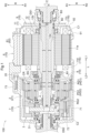
- a cross-sectional view along the axial direction of a vehicle drive device according to an embodiment.
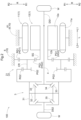
- Skeleton diagram of a vehicle drive device according to an embodiment A partially enlarged view of a cross-sectional view along the axial direction of the vehicle drive device according to the embodiment
- a vehicle drive device 100 includes a rotating electric machine 1 including a stator 11 and a rotor 12, a transmission 2 that changes the speed of rotation transmitted from the rotor 12, and a transmission 2 that changes the speed of rotation transmitted from the rotor 12.
- the differential gear device 3 includes a differential gear device 3 that distributes the driving force from the rotating electric machine 1 transmitted through the vehicle to a pair of wheels W (see FIG. 2) provided on the vehicle, and a case 10 that accommodates the differential gear device 3.
- the direction along the rotational axis of the rotor 12 (see the dashed line in FIG. 1) will be referred to as the "axial direction L.”
- One side in the axial direction L is defined as the “first axial side L1”
- the other side in the axial direction L is defined as the “second axial side L2”.
- the direction perpendicular to the rotational axis of the rotor 12 is referred to as the "radial direction R.”
- the rotation axis side of the rotor 12 is defined as the “radially inner side R1”
- the opposite side is defined as the "radially outer side R2”.
- the direction in which the rotor 12 revolves around its rotational axis is referred to as a "circumferential direction C.”
- the rotating electric machine 1, the transmission 2, and the differential gear device 3 are arranged coaxially.
- the rotating electric machine 1, the transmission 2, and the differential gear device 3 are arranged in the order described from the first axial side L1 to the second axial side L2.
- the rotating electric machine 1 functions as a driving power source for a pair of wheels W (see FIG. 2).
- the rotating electric machine 1 has a function as a motor (electric motor) that receives power supply and generates power, and a function as a generator (generator) that receives power supply and generates power.
- the rotating electrical machine 1 is electrically connected to a power storage device (not shown) such as a battery or a capacitor. Then, the rotating electric machine 1 performs power running using the electric power stored in the power storage device to generate driving force. Further, the rotating electric machine 1 generates power using the driving force transmitted from the pair of wheels W to charge the power storage device.
- the stator 11 of the rotating electric machine 1 includes a cylindrical stator core 11a. Stator core 11a is fixed to case 10.
- the rotor 12 of the rotating electric machine 1 includes a cylindrical rotor core 12a. Rotor core 12a is rotatably supported relative to stator core 11a.
- the rotor 12 further includes a rotor shaft 12b connected to rotate integrally with the rotor core 12a.
- the rotor shaft 12b is formed into a cylindrical shape coaxial with the rotor core 12a.
- the rotating electrical machine 1 is an inner rotor type rotating electrical machine. Therefore, the rotor core 12a is arranged on the radially inner side R1 with respect to the stator core 11a. Further, the rotor shaft 12b is arranged on the radially inner side R1 with respect to the rotor core 12a.
- the rotating electrical machine 1 is a rotating field type rotating electrical machine. Therefore, the stator 11 further includes a stator coil 11b.
- the stator coil 11b includes a first coil end portion 11c that protrudes toward the first axial side L1 with respect to the stator core 11a, and a second coil end portion 11c that protrudes toward the second axial side L2 with respect to the stator core 11a. It is wound around the stator core 11a so that a portion 11d is formed.
- the rotor core 12a is provided with a permanent magnet.
- the transmission 2 includes a planetary gear mechanism 21.
- the planetary gear mechanism 21 includes a sun gear SG, a carrier CR, a first ring gear RG1, and a second ring gear RG2.
- sun gear SG is connected to the rotor 12 so as to rotate integrally with the rotor 12.
- sun gear SG is connected to rotor shaft 12b by welding or the like so as to rotate integrally with rotor shaft 12b.
- the carrier CR is configured to rotatably support the first pinion gear PG1 and the second pinion gear PG2.
- the first pinion gear PG1 and the second pinion gear PG2 are connected to rotate integrally with each other.
- First pinion gear PG1 meshes with sun gear SG and first ring gear RG1.
- the second pinion gear PG2 meshes with the second ring gear RG2.
- the second pinion gear PG2 is formed to have a smaller diameter than the first pinion gear PG1.
- the first ring gear RG1 is connected to the case 10.
- the second ring gear RG2 is arranged on the second axial side L2 with respect to the first ring gear RG1.
- the second ring gear RG2 is connected to the input element of the differential gear device 3 so as to rotate integrally therewith. Note that details of how these ring gears RG1 and RG2 are connected will be described later.
- Each of the sun gear SG, first pinion gear PG1, second pinion gear PG2, first ring gear RG1, and second ring gear RG2 is a helical gear.
- the helical gear is a gear whose tooth traces are inclined with respect to the rotation axis.
- the first ring gear RG1 corresponds to a "first helical gear HG1.”
- the first pinion gear PG1 corresponds to a "second helical gear HG2.”
- the rotation of the rotor 12 is decelerated in the planetary gear mechanism 21 and transmitted to the differential gear device 3. That is, in this embodiment, the transmission 2 functions as a speed reducer that reduces the rotation transmitted from the rotor 12 at a constant speed reduction ratio.
- the differential gear device 3 includes a differential case 31, a shaft member 32, a pinion gear 33, a first side gear 34, and a second side gear 35.
- the pinion gear 33, the first side gear 34, and the second side gear 35 are all bevel gears.
- the differential case 31 is formed to accommodate a pinion gear 33, a first side gear 34, and a second side gear 35.
- the differential case 31 is an input element of the differential gear device 3. Therefore, the differential case 31 is connected to the second ring gear RG2 of the planetary gear mechanism 21 so as to rotate integrally therewith. In the illustrated example, the differential case 31 is connected by welding to the second ring gear RG2 so as to rotate together with the second ring gear RG2.
- the shaft member 32 is arranged to extend along the radial direction R.
- the shaft member 32 is supported by the differential case 31 so as to rotate integrally with the differential case 31.
- a plurality of shaft members 32 are arranged in a distributed manner in the circumferential direction C along the radial direction R (for example, four shaft members 32 are arranged in a cross shape when viewed in the axial direction along the axial direction L). configuration).
- the pinion gear 33 is rotatably supported by the shaft member 32.
- the pinion gear 33 is configured to freely rotate (rotate) about the shaft member 32 and to freely rotate (revolution) about the rotation axis of the differential case 31 .
- a pinion gear 33 is attached to each of the plurality of shaft members 32.
- the first side gear 34 and the second side gear 35 mesh with the pinion gear 33.
- the first side gear 34 and the second side gear 35 are arranged to rotate about the rotation axis of the differential case 31.
- the first side gear 34 is arranged on the first axial side L1 with respect to the shaft member 32.
- the second side gear 35 is arranged on the second axial side L2 with respect to the shaft member 32.
- the first side gear 34 is integrated with the first drive shaft DS1 that is drivingly connected to the wheel W on the first axial side L1 via the output shaft member 4 extending along the axial direction L. It is connected so that it can rotate.
- the output shaft member 4 is inserted into the radially inner side R1 of the first side gear 34 from the first axial side L1, and they are connected to each other by spline engagement.
- the output shaft member 4 is arranged so as to penetrate in the axial direction L through the radially inner side R1 of the transmission 2 and the rotating electric machine 1.
- the output shaft member 4 is arranged to penetrate in the axial direction L through the radially inner side R1 of the sun gear SG of the planetary gear mechanism 21 and the rotor shaft 12b of the rotating electric machine 1.
- the second side gear 35 is connected to rotate integrally with a second drive shaft DS2 that is drivingly connected to the wheel W on the second axial side L2.
- the second drive shaft DS2 is inserted from the axial second side L2 into the radially inner side R1 of the second side gear 35, and they are connected to each other by spline engagement.
- the case 10 includes a first case member 6, a second case member 7, and a support member 8.
- the case 10 further includes a cover member 9.
- the first case member 6 is a member that forms a rotating electrical machine room C1 in which the rotating electrical machine 1 is housed.
- the first case member 6 includes a stator support portion 61 that supports the stator 11 of the rotating electrical machine 1 .
- the first case member 6 further includes a first peripheral wall portion 62.
- the first peripheral wall portion 62 is formed to surround the rotating electrical machine room C1 in the circumferential direction C.
- the first peripheral wall portion 62 is formed in a cylindrical shape that covers the radially outer side R2 of the stator core 11a.
- the stator support portion 61 is formed integrally with the first peripheral wall portion 62.
- the stator core 11a is fixed to the stator support portion 61.
- the first peripheral wall portion 62 does not cover the radially outer side R2 of the first coil end portion 11c and the second coil end portion 11d of the rotating electrical machine 1. That is, in this embodiment, the first case member 6 is configured to form a part of the rotating electrical machine room C1.
- the second case member 7 is a member that forms a gear chamber C2 in which the transmission 2 and the differential gear device 3 are housed.
- the second case member 7 is configured as a separate member from the first case member 6.
- the second case member 7 includes a second peripheral wall portion 71 and a first side wall portion 72.
- the second peripheral wall portion 71 is formed to surround the gear chamber C2 in the circumferential direction C.
- the second peripheral wall portion 71 is formed in a cylindrical shape that covers the radially outer side R2 of the transmission 2 and the differential gear device 3.
- the second peripheral wall portion 71 is formed so as to overlap the entire transmission 2 and differential gear device 3 when viewed in the radial direction R. That is, in this embodiment, the entire transmission 2 and differential gear device 3 are housed in the second case member 7.
- "overlapping when viewed in a specific direction” means that when a virtual straight line parallel to the line of sight is moved in each direction orthogonal to the virtual straight line, the virtual straight line overlaps with the two elements. It means that there is at least a part of the area that intersects both sides of the element.
- the second peripheral wall portion 71 is formed so as to also cover the radially outer side R2 of the second coil end portion 11d of the rotating electrical machine 1. That is, in this embodiment, the second case member 7 is configured to form a part of the rotating electrical machine room C1 in addition to the gear room C2.
- the first side wall portion 72 is formed to cover the second axial side L2 of the gear chamber C2.
- the first side wall part 72 is integrally formed with the second peripheral wall part 71 so as to close the opening on the second axial side L2 of the second peripheral wall part 71.
- a through hole is formed in the first side wall portion 72 so as to penetrate in the axial direction L, through which a connecting portion of the second side gear 35 to the second drive shaft DS2 is inserted.
- the cover member 9 is configured as a separate member from the first case member 6 and the second case member 7.
- the cover member 9 includes a third peripheral wall portion 91 and a second side wall portion 92.
- the third peripheral wall portion 91 is formed to surround the rotating electrical machine room C1.
- the third peripheral wall portion 91 is formed in a cylindrical shape that covers the radially outer side R2 of the first coil end portion 11c of the rotating electrical machine 1. That is, in this embodiment, the cover member 9 is configured to form a part of the rotating electrical machine room C1.
- the second side wall portion 92 is formed to cover the first axial side L1 of the rotating electrical machine room C1.
- the second side wall part 92 is integrally formed with the third peripheral wall part 91 so as to close the opening on the first axial side L1 of the third peripheral wall part 91.
- the second side wall portion 92 rotatably supports a portion of the rotor shaft 12b that protrudes from the rotor core 12a toward the first axial side L1 via the second bearing B2.
- a through hole is formed in the second side wall portion 92 so as to penetrate in the axial direction L, into which the connecting portion of the output shaft member 4 to the first drive shaft DS1 is inserted.
- the second side wall portion 92 rotatably supports the connecting portion of the output shaft member 4 to the first drive shaft DS1 via the third bearing B3.
- the first case member 6 is joined to the second case member 7 from the first axial side L1. That is, in the axial direction L, the side on which the first case member 6 is disposed with respect to the second case member 7 is the first axial side L1.
- the first case member 6 and the second case member 7 are joined to each other in the axial direction L.
- the first case member 6 and the second case member 7 are joined such that the first circumferential wall portion 62 and the second circumferential wall portion 71 are in contact with each other in the axial direction L.
- the cover member 9 is joined to the first case member 6 from the first axial side L1.
- the cover member 9 and the first case member 6 are joined so that the third peripheral wall portion 91 and the first peripheral wall portion 62 are in contact with each other in the axial direction L.
- the support member 8 is configured to support the first helical gear HG1 in the axial direction L. Further, the support member 8 is configured to rotatably support the rotor 12 via the first bearing B1. Note that the first bearing B1 corresponds to a "rotor bearing”. Further, the support member 8 is fixed to the second case member 7. In this embodiment, the support member 8 is formed so as to partition the rotating electrical machine room C1 and the gear room C2. In the illustrated example, the support member 8 is disposed between the rotating electrical machine 1 and the transmission 2 in the axial direction L.
- the vehicle drive device 100 is A rotating electrical machine 1 including a stator 11 and a rotor 12; a transmission 2 that changes the speed of the rotation transmitted from the rotor 12; a differential gear device 3 that distributes the driving force from the rotating electrical machine 1 transmitted via the transmission 2 to a pair of wheels W included in the vehicle;
- a vehicle drive device 100 comprising a rotating electric machine 1, a transmission 2, and a case 10 that accommodates a differential gear device 3,
- a rotating electrical machine 1, a transmission 2, and a differential gear device 3 are arranged coaxially
- the transmission 2 includes a first helical gear HG1 and a second helical gear HG2 that meshes with the first helical gear HG1,
- the direction along the rotational axis of the rotor 12 is defined as the axial direction L
- the case 10 is composed of a first case member 6 including a stator support part 61 that supports the stator 11, and a separate member from the first case member 6, and houses the transmission 2 and the differential gear device 3.
- the support member 8 rotatably supports the rotor 12 via a first bearing B1 serving as a rotor bearing, and is fixed to the second case member 7.
- the thrust force F acting on the first helical gear HG1 due to meshing with the second helical gear HG2 is applied to the support member 8 that supports the first helical gear HG1 in the axial direction L.
- the signal is transmitted to the second case member 7 via the support member 8 and the second case member 7, and is supported by the support member 8 and the second case member 7.
- the thrust force F transmitted to the second case member 7 is difficult to be transmitted to the first case member 6. Therefore, the strain generated in the stator support portion 61 by the thrust force F transmitted via the support member 8 that supports the first helical gear HG1 in the axial direction L can be suppressed to a small level.
- the support member 8 in addition to supporting the first helical gear HG1 in the axial direction L, can also freely rotate the rotor 12 via the first bearing B1 as a rotor bearing. I support it. In this way, the first helical gear HG1 and the first bearing B1 are supported by one support member 8. Thereby, compared to a configuration in which the first bearing B1 is supported by a member separate from the support member 8, the vehicle drive device 100 can be made smaller.
- first case member 6 and the second case member 7 are joined to each other in the axial direction L,
- the entire transmission 2 and differential gear device 3 are housed in the second case member 7.
- the rotating electrical machine chamber C1 in which the rotating electrical machine 1 is accommodated is connected to the first case member 6. Easy to secure widely on the side.
- the second case member 7 includes a fastened portion 73 to which the support member 8 is fastened by the fastening member 20.
- the fastened portion 73 is formed so that the fastening member 20 is fixed from the first axial side L1.
- the fastened portion 73 is formed with a joint surface 7a facing the first axial side L1.
- the fastening member 20 is a bolt.
- a screw hole into which the threaded portion of the fastening member 20 is screwed is formed in the fastened portion 73 so as to open to the joint surface 7a.
- the support member 8 includes a bearing support part 81, a fastening part 82, an abutting part 83, and an engaging part 84.
- the bearing support part 81 is configured to support the first bearing B1.
- the bearing support part 81 is configured such that a portion of the rotor shaft 12b that protrudes from the rotor core 12a to the second axial side L2 penetrates in the axial direction L through the radially inner side R1 of the bearing support part 81. is formed.
- the bearing support portion 81 rotatably supports a portion of the rotor shaft 12b that protrudes from the rotor core 12a toward the second axial side L2 via the first bearing B1.
- the fastening portion 82 is configured to be fastened to the fastened portion 73 of the second case member 7 by the fastening member 20.
- the fastening portion 82 is fastened and fixed to the fastened portion 73 using the fastening member 20 while contacting the joint surface 7a from the first axial side L1.
- the plurality of fastening portions 82 are arranged at intervals in the circumferential direction C. Further, in this example, a through hole into which a threaded portion of the fastening member 20 as a bolt is inserted is formed to penetrate through the fastening portion 82 in the axial direction L.
- the contact portion 83 is configured such that the first helical gear HG1 contacts in the axial direction L.
- the contact portion 83 is arranged such that the first ring gear RG1 as the first helical gear HG1 contacts the contact portion 83 from the second axial side L2.
- the contact portion 83 extends in the radial direction R and the circumferential direction C so as to connect the bearing support portion 81 and the fastening portion 82.
- the bearing support portion 81 is integrally formed at the end portion of the contact portion 83 on the radially inner side R1.
- a fastening portion 82 is integrally formed at the radially outer end R2 of the contact portion 83.
- the engaging portion 84 is configured to engage with the first helical gear HG1.
- the engaging portion 84 is formed so that the first ring gear RG1 as the first helical gear HG1 is slidably engaged in the axial direction L and unrotatably engaged in the circumferential direction C.
- the engaging portion 84 protrudes from the contact portion 83 to the second axial side L2 so as to be located on the radially inner side R1 with respect to the first ring gear RG1, and further protrudes to the radially outer side R2.
- the first ring gear RG1 is restricted from moving relative to the engagement portion 84 toward the first axial side L1 by abutting the contact portion 83 from the second axial side L2.
- the regulating member 30 such as a snap ring is provided on the inner peripheral portion of the first ring gear RG1 so that the engaging portion 84 comes into contact with it from the second axial side L2. Therefore, the first ring gear RG1 is restricted from moving relative to the engagement portion 84 toward the second axial side L2 by the restriction member 30.
- the first ring gear RG1 as the first helical gear HG1 is engaged with the support member 8 so as not to be relatively rotatable. That is, in this embodiment, the support member 8 supports the first helical gear HG1 in the axial direction L and the circumferential direction C.
- the second case member 7 includes the joint surface 7a facing the first axial side L1
- the support member 8 is fastened and fixed to the second case member 7 using a fastening member 20 in a state in which it is in contact with the joint surface 7a from the first axial side L1, and is fastened and fixed to the second case member 7 using the fastening member 20. is supported in the axial direction L and the circumferential direction C.
- the thrust force F from the first helical gear HG1 can be appropriately supported by the support member 8. Further, since the thrust force F acting on the support member 8 acts in the axial direction L with respect to the joint surface 7a of the second case member 7, distortion of the second case member 7 can be easily suppressed. Therefore, the distortion of the first case member 6 can also be easily suppressed.
- the first helical gear is engaged with the second helical gear HG2.
- the thrust force F acting on HG1 acts toward the first axial side L1.
- the thrust force F directed toward the first axial side L1 from the first helical gear HG1 is received by the contact portion 83 of the support member 8.
- the thrust force F directed toward the first axial side L1 from the first helical gear HG1 can be appropriately supported by the support member 8 while the vehicle is moving forward.
- the transmission 2 includes a planetary gear mechanism 21 having a carrier CR and a first ring gear RG1,
- the carrier CR is configured to rotatably support the first pinion gear PG1 that meshes with the first ring gear RG1
- the second helical gear HG2 is the first pinion gear PG1
- the first helical gear HG1 is a first ring gear RG1, and is engaged with the support member 8 so as not to be relatively rotatable.
- the planetary gear mechanism 21 further includes a sun gear SG and a second ring gear RG2, Sun gear SG is connected to rotate integrally with rotor 12,
- the second ring gear RG2 is arranged on the second axial side L2 with respect to the first ring gear RG1,
- the carrier CR is configured to rotatably support a second pinion gear PG2 in addition to the first pinion gear PG1,
- a first pinion gear PG1 and a second pinion gear PG2 are connected to rotate integrally with each other,
- the first pinion gear PG1 meshes with the sun gear SG and the first ring gear RG1,
- the second pinion gear PG2 has a smaller diameter than the first pinion gear PG1, and meshes with the second ring gear RG2.
- the transmission 2 can be configured as a reduction gear having a large reduction ratio.
- the transmission 2 includes the planetary gear mechanism 21 having the sun gear SG, the carrier CR, the first ring gear RG1, and the second ring gear RG2, and the first ring gear RG1 and the first pinion gear PG1 are
- the planetary gear mechanism 21 is a single pinion type planetary gear mechanism, and the ring gear of the planetary gear mechanism and the pinion gear meshing with the ring gear are each a first gear.
- a configuration may be adopted in which the helical gear HG1 and the second helical gear HG2 are used.
- the transmission 2 has been described as an example of a configuration in which it functions as a speed reducer that reduces the rotation transmitted from the rotor 12 at a constant speed reduction ratio.
- the present invention is not limited to such a configuration, and, for example, the transmission 2 may be a transmission capable of switching to a plurality of gears.
- the first helical gear HG1 is engaged with the support member 8 in a manner that it cannot rotate relative to the support member 8.
- the configuration is not limited to such a configuration, and the first helical gear HG1 may be supported so as to be relatively rotatable with respect to the support member 8.
- a thrust bearing may be arranged between the first helical gear HG1 and the support member 8 in the axial direction L.
- first case member 6 and the second case member 7 are joined to each other in the axial direction L, as an example.
- another case member may be interposed between the first case member 6 and the second case member 7 in the axial direction L.
- the structure in which the support member 8 is fastened and fixed to the second case member 7 using a bolt as the fastening member 20 has been described as an example.
- the support member 8 may be fixed to the second case member 7 by, for example, welding, riveting, or the like.
- the case 10 has been described as an example in which the case 10 includes the cover member 9 in addition to the first case member 6, the second case member 7, and the support member 8.
- the case 10 may be configured without the cover member 9.
- the first case member 6 includes a wall portion corresponding to the cover member 9 (specifically, the third peripheral wall portion 91 and the second side wall portion 92).
- the case 10 may include another member in addition to the first case member 6, the second case member 7, the support member 8, and the cover member 9.
- the vehicle drive device (100) includes: A rotating electric machine (1) including a stator (11) and a rotor (12); a transmission (2) that changes the speed of the rotation transmitted from the rotor (12); a differential gear device (3) that distributes the driving force from the rotating electrical machine (1) transmitted via the transmission (2) to a pair of wheels (W) included in the vehicle; A vehicle drive device (100) comprising a case (10) that accommodates the rotating electric machine (1), the transmission (2), and the differential gear device (3), The rotating electric machine (1), the transmission (2), and the differential gear device (3) are arranged coaxially,
- the transmission (2) includes a first helical gear (HG1) and a second helical gear (HG2) that meshes with the first helical gear (HG1),
- the direction along the rotational axis of the rotor (12) is defined as the axial direction (L)
- the case (10) is composed of a first case member (6) including a stator support part (61) that supports the stator (11), and a separate member from the first case
- the support member (8) rotatably supports the rotor (12) via a rotor bearing (B1) and is fixed to the second case member (7).
- (L) is transmitted to the second case member (7) via the support member (8) supported by the support member (8) and the second case member (7).
- the thrust force (F) transmitted to the second case member (7) is transmitted to the first case member (7). (6) is difficult to convey.
- the strain generated in the stator support portion (61) due to the thrust force (F) transmitted through the support member (8) that supports the first helical gear (HG1) in the axial direction (L) can be suppressed to a small level. Can be done. As a result, deformation of the stator (11) supported by the stator support portion (61) and deterioration of the performance of the rotating electric machine (1) can be avoided. Further, according to this configuration, the support member (8) not only supports the first helical gear (HG1) in the axial direction (L), but also supports the rotor (8) via the rotor bearing (B1). 12) is also rotatably supported.
- the first helical gear (HG1) and the rotor bearing (B1) are supported by one support member (8).
- the vehicle drive device (100) can be made smaller in size compared to a configuration in which the rotor bearing (B1) is supported by a member separate from the support member (8).
- the side where the first case member (6) is arranged with respect to the second case member (7) is defined as the first axial side (L1)
- (F) preferably acts toward the first axial side (L1).
- the thrust force (F) directed toward the first axial side (L1) from the first helical gear (HG1) is appropriately supported by the support member (8). be able to.
- first case member (6) and the second case member (7) are joined to each other in the axial direction (L), It is preferable that the transmission (2) and the differential gear device (3) are entirely housed in the second case member (7).
- the direction in which the rotor (12) revolves around the rotation axis is defined as a circumferential direction (C), and in the axial direction (L), the first case member (6) is relative to the second case member (7).
- the second case member (7) includes a joint surface (7a) facing the first axial side (L1)
- the support member (8) is attached to the second case member (7) using the fastening member (20) while in contact with the joint surface (7a) from the first axial side (L1).
- the first helical gear (HG1) is fastened and fixed and supports the first helical gear (HG1) in the axial direction (L) and the circumferential direction (C).
- the thrust force (F) from the first helical gear (HG1) can be appropriately supported by the support member (8).
- the thrust force (F) acting on the support member (8) acts in the axial direction (L) with respect to the joint surface (7a) of the second case member (7), the second case member It is easy to suppress the distortion in (7). Therefore, distortion of the first case member (6) can also be easily suppressed.
- the technology according to the present disclosure includes a rotating electrical machine, a transmission that changes the speed of rotation transmitted from a rotor of the rotating electrical machine, and a driving force that is transmitted from the rotating electrical machine and distributed through the transmission to a pair of wheels.
- the present invention can be used in a vehicle drive device that includes a differential gear device and a case that accommodates the differential gear device.
Landscapes
- Engineering & Computer Science (AREA)
- General Engineering & Computer Science (AREA)
- Mechanical Engineering (AREA)
- Chemical & Material Sciences (AREA)
- Combustion & Propulsion (AREA)
- Transportation (AREA)
- Connection Of Motors, Electrical Generators, Mechanical Devices, And The Like (AREA)
- General Details Of Gearings (AREA)
Abstract
Description
ステータ及びロータを備えた回転電機と、
前記ロータから伝達される回転を変速する変速機と、
前記変速機を介して伝達される前記回転電機からの駆動力を、車両が備える一対の車輪に分配する差動歯車装置と、
前記回転電機、前記変速機、及び前記差動歯車装置を収容するケースと、を備えた車両用駆動装置であって、
前記回転電機と前記変速機と前記差動歯車装置とが、同軸上に配置され、
前記変速機は、第1はすば歯車と、前記第1はすば歯車に噛み合う第2はすば歯車と、を備え、
前記ロータの回転軸心に沿う方向を軸方向として、
前記ケースは、前記ステータを支持するステータ支持部を備えた第1ケース部材と、前記第1ケース部材とは別部材で構成され、前記変速機及び前記差動歯車装置が収容されるギヤ室を形成する第2ケース部材と、前記第1はすば歯車を前記軸方向に支持する支持部材と、を備え、
前記支持部材は、ロータ軸受を介して前記ロータを回転自在に支持すると共に、前記第2ケース部材に固定されている点にある。
また、本特徴構成によれば、支持部材は、第1はすば歯車を軸方向に支持しているのに加えて、ロータ軸受を介してロータも回転自在に支持している。このように、第1はすば歯車とロータ軸受が、1つの支持部材により支持されている。これにより、支持部材とは別部材によってロータ軸受が支持された構成に比べて、車両用駆動装置を小型化することができる。
ステータ11及びロータ12を備えた回転電機1と、
ロータ12から伝達される回転を変速する変速機2と、
変速機2を介して伝達される回転電機1からの駆動力を、車両が備える一対の車輪Wに分配する差動歯車装置3と、
回転電機1、変速機2、及び差動歯車装置3を収容するケース10と、を備えた車両用駆動装置100であって、
回転電機1と変速機2と差動歯車装置3とが、同軸上に配置され、
変速機2は、第1はすば歯車HG1と、当該第1はすば歯車HG1に噛み合う第2はすば歯車HG2と、を備え、
ロータ12の回転軸心に沿う方向を軸方向Lとして、
ケース10は、ステータ11を支持するステータ支持部61を備えた第1ケース部材6と、当該第1ケース部材6とは別部材で構成され、変速機2及び差動歯車装置3が収容されるギヤ室C2を形成する第2ケース部材7と、第1はすば歯車HG1を軸方向Lに支持する支持部材8と、を備え、
支持部材8は、ロータ軸受としての第1軸受B1を介してロータ12を回転自在に支持すると共に、第2ケース部材7に固定されている。
また、本構成によれば、支持部材8は、第1はすば歯車HG1を軸方向Lに支持しているのに加えて、ロータ軸受としての第1軸受B1を介してロータ12も回転自在に支持している。このように、第1はすば歯車HG1と第1軸受B1が、1つの支持部材8により支持されている。これにより、支持部材8とは別部材によって第1軸受B1が支持された構成に比べて、車両用駆動装置100を小型化することができる。
変速機2及び差動歯車装置3の全体が、第2ケース部材7に収容されている。
支持部材8は、接合面7aに対して軸方向第1側L1から当接した状態で、締結部材20を用いて第2ケース部材7に締結固定されていると共に、第1はすば歯車HG1を軸方向L及び周方向Cに支持している。
キャリヤCRは、第1リングギヤRG1に噛み合う第1ピニオンギヤPG1を回転自在に支持するように構成され、
第2はすば歯車HG2は、第1ピニオンギヤPG1であり、
第1はすば歯車HG1は、第1リングギヤRG1であり、支持部材8に対して相対回転不能に係合されている。
遊星歯車機構21は、サンギヤSG及び第2リングギヤRG2を更に備え、
サンギヤSGは、ロータ12と一体的に回転するように連結され、
第2リングギヤRG2は、第1リングギヤRG1に対して軸方向第2側L2に配置され、
キャリヤCRは、第1ピニオンギヤPG1に加えて、第2ピニオンギヤPG2を回転自在に支持するように構成され、
第1ピニオンギヤPG1と第2ピニオンギヤPG2とが、互いに一体的に回転するように連結され、
第1ピニオンギヤPG1は、サンギヤSGと第1リングギヤRG1とに噛み合い、
第2ピニオンギヤPG2は、第1ピニオンギヤPG1よりも小径であり、第2リングギヤRG2に噛み合っている。
(1)上記の実施形態では、変速機2が、サンギヤSG、キャリヤCR、第1リングギヤRG1、及び第2リングギヤRG2を有する遊星歯車機構21を備え、第1リングギヤRG1及び第1ピニオンギヤPG1が、それぞれ第1はすば歯車HG1及び第2はすば歯車HG2である構成を例として説明した。しかし、そのような構成に限定されることなく、例えば、遊星歯車機構21がシングルピニオン型の遊星歯車機構であり、当該遊星歯車機構のリングギヤ、及び当該リングギヤに噛み合うピニオンギヤが、それぞれ第1はすば歯車HG1及び第2はすば歯車HG2である構成としても良い。
以下では、上記において説明した車両用駆動装置(100)の概要について説明する。
ステータ(11)及びロータ(12)を備えた回転電機(1)と、
前記ロータ(12)から伝達される回転を変速する変速機(2)と、
前記変速機(2)を介して伝達される前記回転電機(1)からの駆動力を、車両が備える一対の車輪(W)に分配する差動歯車装置(3)と、
前記回転電機(1)、前記変速機(2)、及び前記差動歯車装置(3)を収容するケース(10)と、を備えた車両用駆動装置(100)であって、
前記回転電機(1)と前記変速機(2)と前記差動歯車装置(3)とが、同軸上に配置され、
前記変速機(2)は、第1はすば歯車(HG1)と、前記第1はすば歯車(HG1)に噛み合う第2はすば歯車(HG2)と、を備え、
前記ロータ(12)の回転軸心に沿う方向を軸方向(L)として、
前記ケース(10)は、前記ステータ(11)を支持するステータ支持部(61)を備えた第1ケース部材(6)と、前記第1ケース部材(6)とは別部材で構成され、前記変速機(2)及び前記差動歯車装置(3)が収容されるギヤ室(C2)を形成する第2ケース部材(7)と、前記第1はすば歯車(HG1)を前記軸方向(L)に支持する支持部材(8)と、を備え、
前記支持部材(8)は、ロータ軸受(B1)を介して前記ロータ(12)を回転自在に支持すると共に、前記第2ケース部材(7)に固定されている。
また、本構成によれば、支持部材(8)は、第1はすば歯車(HG1)を軸方向(L)に支持しているのに加えて、ロータ軸受(B1)を介してロータ(12)も回転自在に支持している。このように、第1はすば歯車(HG1)とロータ軸受(B1)が、1つの支持部材(8)により支持されている。これにより、支持部材(8)とは別部材によってロータ軸受(B1)が支持された構成に比べて、車両用駆動装置(100)を小型化することができる。
前記車両が前進するように前記回転電機(1)が駆動している場合に、前記第2はすば歯車(HG2)との噛み合いにより前記第1はすば歯車(HG1)に作用するスラスト力(F)は、前記軸方向第1側(L1)に向けて作用すると好適である。
前記変速機(2)及び前記差動歯車装置(3)の全体が、前記第2ケース部材(7)に収容されていると好適である。
前記第2ケース部材(7)は、前記軸方向第1側(L1)を向く接合面(7a)を備え、
前記支持部材(8)は、前記接合面(7a)に対して前記軸方向第1側(L1)から当接した状態で、締結部材(20)を用いて前記第2ケース部材(7)に締結固定されていると共に、前記第1はすば歯車(HG1)を前記軸方向(L)及び前記周方向(C)に支持していると好適である。
Claims (4)
- ステータ及びロータを備えた回転電機と、
前記ロータから伝達される回転を変速する変速機と、
前記変速機を介して伝達される前記回転電機からの駆動力を、車両が備える一対の車輪に分配する差動歯車装置と、
前記回転電機、前記変速機、及び前記差動歯車装置を収容するケースと、を備えた車両用駆動装置であって、
前記回転電機と前記変速機と前記差動歯車装置とが、同軸上に配置され、
前記変速機は、第1はすば歯車と、前記第1はすば歯車に噛み合う第2はすば歯車と、を備え、
前記ロータの回転軸心に沿う方向を軸方向として、
前記ケースは、前記ステータを支持するステータ支持部を備えた第1ケース部材と、前記第1ケース部材とは別部材で構成され、前記変速機及び前記差動歯車装置が収容されるギヤ室を形成する第2ケース部材と、前記第1はすば歯車を前記軸方向に支持する支持部材と、を備え、
前記支持部材は、ロータ軸受を介して前記ロータを回転自在に支持すると共に、前記第2ケース部材に固定されている、車両用駆動装置。 - 前記軸方向において、前記第2ケース部材に対して前記第1ケース部材が配置されている側を軸方向第1側として、
前記車両が前進するように前記回転電機が駆動している場合に、前記第2はすば歯車との噛み合いにより前記第1はすば歯車に作用するスラスト力は、前記軸方向第1側に向けて作用する、請求項1に記載の車両用駆動装置。 - 前記第1ケース部材と前記第2ケース部材とが、互いに前記軸方向に接合され、
前記変速機及び前記差動歯車装置の全体が、前記第2ケース部材に収容されている、請求項1又は2に記載の車両用駆動装置。 - 前記ロータの前記回転軸心を周回する方向を周方向とし、前記軸方向において、前記第2ケース部材に対して前記第1ケース部材が配置されている側を軸方向第1側とし、前記軸方向第1側とは反対側を軸方向第2側として、
前記第2ケース部材は、前記軸方向第1側を向く接合面を備え、
前記支持部材は、前記接合面に対して前記軸方向第1側から当接した状態で、締結部材を用いて前記第2ケース部材に締結固定されていると共に、前記第1はすば歯車を前記軸方向及び前記周方向に支持している、請求項1又は2に記載の車両用駆動装置。
Priority Applications (5)
| Application Number | Priority Date | Filing Date | Title |
|---|---|---|---|
| JP2024510206A JPWO2023182326A1 (ja) | 2022-03-25 | 2023-03-22 | |
| EP23774921.3A EP4428399A4 (en) | 2022-03-25 | 2023-03-22 | VEHICLE DRIVE DEVICE |
| CN202380016237.6A CN118511017A (zh) | 2022-03-25 | 2023-03-22 | 车用驱动装置 |
| US18/714,362 US12338884B2 (en) | 2022-03-05 | 2023-03-22 | Vehicle drive device |
| JP2025063215A JP7803453B2 (ja) | 2022-03-25 | 2025-04-07 | 車両用駆動装置 |
Applications Claiming Priority (2)
| Application Number | Priority Date | Filing Date | Title |
|---|---|---|---|
| JP2022-050088 | 2022-03-25 | ||
| JP2022050088 | 2022-03-25 |
Publications (1)
| Publication Number | Publication Date |
|---|---|
| WO2023182326A1 true WO2023182326A1 (ja) | 2023-09-28 |
Family
ID=88101133
Family Applications (1)
| Application Number | Title | Priority Date | Filing Date |
|---|---|---|---|
| PCT/JP2023/011121 Ceased WO2023182326A1 (ja) | 2022-03-05 | 2023-03-22 | 車両用駆動装置 |
Country Status (5)
| Country | Link |
|---|---|
| US (1) | US12338884B2 (ja) |
| EP (1) | EP4428399A4 (ja) |
| JP (2) | JPWO2023182326A1 (ja) |
| CN (1) | CN118511017A (ja) |
| WO (1) | WO2023182326A1 (ja) |
Cited By (1)
| Publication number | Priority date | Publication date | Assignee | Title |
|---|---|---|---|---|
| EP4592552A1 (en) * | 2024-01-29 | 2025-07-30 | Volvo Truck Corporation | A transmission for a vehicle |
Families Citing this family (2)
| Publication number | Priority date | Publication date | Assignee | Title |
|---|---|---|---|---|
| EP4502425A4 (en) * | 2022-08-12 | 2025-09-03 | Aisin Corp | VEHICLE DRIVE DEVICE |
| JP2024157674A (ja) * | 2023-04-26 | 2024-11-08 | ヤマハ発動機株式会社 | 船外機および船舶 |
Citations (4)
| Publication number | Priority date | Publication date | Assignee | Title |
|---|---|---|---|---|
| US20060009324A1 (en) * | 2002-09-02 | 2006-01-12 | Karl-Heinz Keuth | Directly driven drive axle with a gear train comprising an axially-fixed sun pinion |
| JP2019074205A (ja) | 2017-10-13 | 2019-05-16 | アイシン・エィ・ダブリュ株式会社 | 車両用駆動装置 |
| JP2019122068A (ja) * | 2017-12-28 | 2019-07-22 | アイシン・エィ・ダブリュ株式会社 | 車両用駆動装置 |
| JP2022030222A (ja) * | 2020-08-06 | 2022-02-18 | 株式会社ジェイテクト | 駆動装置 |
Family Cites Families (8)
| Publication number | Priority date | Publication date | Assignee | Title |
|---|---|---|---|---|
| JPH07293644A (ja) * | 1994-04-25 | 1995-11-07 | Toyota Motor Corp | 遊星歯車装置 |
| JP2002104001A (ja) * | 2000-09-29 | 2002-04-09 | Exedy Corp | 電気自動車の減速装置及びその減速比設定方法 |
| WO2015039610A1 (zh) * | 2013-09-22 | 2015-03-26 | 格源动力有限公司 | 带一级变速的同轴电机 |
| CN106740086A (zh) * | 2016-12-23 | 2017-05-31 | 格源动力有限公司 | 一种同轴输入输出的变矩差速驱动装置 |
| JP2018189192A (ja) * | 2017-05-09 | 2018-11-29 | アイシン・エィ・ダブリュ株式会社 | 車両用駆動装置 |
| EP3663609B1 (en) * | 2017-10-13 | 2023-08-30 | Aisin Corporation | Drive device for vehicle |
| JP2021095952A (ja) * | 2019-12-17 | 2021-06-24 | 本田技研工業株式会社 | 動力伝達装置の潤滑構造 |
| JP7694685B2 (ja) * | 2021-10-20 | 2025-06-18 | 株式会社アイシン | 車両用駆動装置 |
-
2023
- 2023-03-22 EP EP23774921.3A patent/EP4428399A4/en active Pending
- 2023-03-22 US US18/714,362 patent/US12338884B2/en active Active
- 2023-03-22 JP JP2024510206A patent/JPWO2023182326A1/ja active Pending
- 2023-03-22 WO PCT/JP2023/011121 patent/WO2023182326A1/ja not_active Ceased
- 2023-03-22 CN CN202380016237.6A patent/CN118511017A/zh active Pending
-
2025
- 2025-04-07 JP JP2025063215A patent/JP7803453B2/ja active Active
Patent Citations (4)
| Publication number | Priority date | Publication date | Assignee | Title |
|---|---|---|---|---|
| US20060009324A1 (en) * | 2002-09-02 | 2006-01-12 | Karl-Heinz Keuth | Directly driven drive axle with a gear train comprising an axially-fixed sun pinion |
| JP2019074205A (ja) | 2017-10-13 | 2019-05-16 | アイシン・エィ・ダブリュ株式会社 | 車両用駆動装置 |
| JP2019122068A (ja) * | 2017-12-28 | 2019-07-22 | アイシン・エィ・ダブリュ株式会社 | 車両用駆動装置 |
| JP2022030222A (ja) * | 2020-08-06 | 2022-02-18 | 株式会社ジェイテクト | 駆動装置 |
Non-Patent Citations (1)
| Title |
|---|
| See also references of EP4428399A4 |
Cited By (1)
| Publication number | Priority date | Publication date | Assignee | Title |
|---|---|---|---|---|
| EP4592552A1 (en) * | 2024-01-29 | 2025-07-30 | Volvo Truck Corporation | A transmission for a vehicle |
Also Published As
| Publication number | Publication date |
|---|---|
| JPWO2023182326A1 (ja) | 2023-09-28 |
| JP2025096420A (ja) | 2025-06-26 |
| JP7803453B2 (ja) | 2026-01-21 |
| US20240401683A1 (en) | 2024-12-05 |
| EP4428399A1 (en) | 2024-09-11 |
| EP4428399A4 (en) | 2025-04-23 |
| US12338884B2 (en) | 2025-06-24 |
| CN118511017A (zh) | 2024-08-16 |
Similar Documents
| Publication | Publication Date | Title |
|---|---|---|
| WO2023182326A1 (ja) | 車両用駆動装置 | |
| US20250018788A1 (en) | Drive device for vehicle | |
| US11802614B2 (en) | Vehicle drive device | |
| US11027616B2 (en) | Vehicle driving device | |
| JP6596897B2 (ja) | モータ駆動装置 | |
| JP2014024412A (ja) | 車両用駆動装置 | |
| JP7448028B2 (ja) | 車両用駆動装置 | |
| JP2020085026A (ja) | 車両用駆動伝達装置 | |
| CN110997382A (zh) | 电动车辆驱动装置 | |
| US12066091B2 (en) | Vehicle drive device | |
| JP2023150296A (ja) | 車両用駆動装置 | |
| WO2025115344A1 (ja) | 車両用駆動装置 | |
| JP2023150297A (ja) | 車両用駆動装置 | |
| JP7711849B2 (ja) | 車両用駆動装置 | |
| US12539747B2 (en) | Drive device for vehicle | |
| US20250296416A1 (en) | Transaxle | |
| JP4400621B2 (ja) | 相対回転状態検知装置 | |
| JP2024100584A (ja) | 動力伝達装置 | |
| JP2024090827A (ja) | 車両用駆動装置 | |
| WO2025141947A1 (ja) | 車両用駆動装置 | |
| JP2023125606A (ja) | 車両用駆動装置 | |
| JP2023089764A (ja) | 車両用駆動装置 | |
| JP2024098797A (ja) | 車両用駆動装置 | |
| JP2018204622A (ja) | 動力伝達装置 |
Legal Events
| Date | Code | Title | Description |
|---|---|---|---|
| 121 | Ep: the epo has been informed by wipo that ep was designated in this application |
Ref document number: 23774921 Country of ref document: EP Kind code of ref document: A1 |
|
| WWE | Wipo information: entry into national phase |
Ref document number: 18714362 Country of ref document: US |
|
| WWE | Wipo information: entry into national phase |
Ref document number: 2024510206 Country of ref document: JP |
|
| WWE | Wipo information: entry into national phase |
Ref document number: 2023774921 Country of ref document: EP |
|
| ENP | Entry into the national phase |
Ref document number: 2023774921 Country of ref document: EP Effective date: 20240606 |
|
| WWE | Wipo information: entry into national phase |
Ref document number: 202380016237.6 Country of ref document: CN |
|
| NENP | Non-entry into the national phase |
Ref country code: DE |
|
| WWG | Wipo information: grant in national office |
Ref document number: 18714362 Country of ref document: US |