WO2023184355A1 - 正极活性材料、其制备方法以及包含其的正极极片、二次电池及用电装置 - Google Patents
正极活性材料、其制备方法以及包含其的正极极片、二次电池及用电装置 Download PDFInfo
- Publication number
- WO2023184355A1 WO2023184355A1 PCT/CN2022/084447 CN2022084447W WO2023184355A1 WO 2023184355 A1 WO2023184355 A1 WO 2023184355A1 CN 2022084447 W CN2022084447 W CN 2022084447W WO 2023184355 A1 WO2023184355 A1 WO 2023184355A1
- Authority
- WO
- WIPO (PCT)
- Prior art keywords
- active material
- positive electrode
- group
- range
- optionally
- Prior art date
- Legal status (The legal status is an assumption and is not a legal conclusion. Google has not performed a legal analysis and makes no representation as to the accuracy of the status listed.)
- Ceased
Links
Images




Classifications
-
- H—ELECTRICITY
- H01—ELECTRIC ELEMENTS
- H01M—PROCESSES OR MEANS, e.g. BATTERIES, FOR THE DIRECT CONVERSION OF CHEMICAL ENERGY INTO ELECTRICAL ENERGY
- H01M4/00—Electrodes
- H01M4/02—Electrodes composed of, or comprising, active material
- H01M4/36—Selection of substances as active materials, active masses, active liquids
- H01M4/362—Composites
- H01M4/366—Composites as layered products
-
- C—CHEMISTRY; METALLURGY
- C01—INORGANIC CHEMISTRY
- C01B—NON-METALLIC ELEMENTS; COMPOUNDS THEREOF; METALLOIDS OR COMPOUNDS THEREOF NOT COVERED BY SUBCLASS C01C
- C01B25/00—Phosphorus; Compounds thereof
- C01B25/16—Oxyacids of phosphorus; Salts thereof
- C01B25/26—Phosphates
- C01B25/45—Phosphates containing plural metal, or metal and ammonium
-
- H—ELECTRICITY
- H01—ELECTRIC ELEMENTS
- H01M—PROCESSES OR MEANS, e.g. BATTERIES, FOR THE DIRECT CONVERSION OF CHEMICAL ENERGY INTO ELECTRICAL ENERGY
- H01M4/00—Electrodes
- H01M4/02—Electrodes composed of, or comprising, active material
- H01M4/13—Electrodes for accumulators with non-aqueous electrolyte, e.g. for lithium-accumulators; Processes of manufacture thereof
- H01M4/133—Electrodes based on carbonaceous material, e.g. graphite-intercalation compounds or CFx
-
- H—ELECTRICITY
- H01—ELECTRIC ELEMENTS
- H01M—PROCESSES OR MEANS, e.g. BATTERIES, FOR THE DIRECT CONVERSION OF CHEMICAL ENERGY INTO ELECTRICAL ENERGY
- H01M4/00—Electrodes
- H01M4/02—Electrodes composed of, or comprising, active material
- H01M4/13—Electrodes for accumulators with non-aqueous electrolyte, e.g. for lithium-accumulators; Processes of manufacture thereof
- H01M4/136—Electrodes based on inorganic compounds other than oxides or hydroxides, e.g. sulfides, selenides, tellurides, halogenides or LiCoFy
-
- H—ELECTRICITY
- H01—ELECTRIC ELEMENTS
- H01M—PROCESSES OR MEANS, e.g. BATTERIES, FOR THE DIRECT CONVERSION OF CHEMICAL ENERGY INTO ELECTRICAL ENERGY
- H01M4/00—Electrodes
- H01M4/02—Electrodes composed of, or comprising, active material
- H01M4/36—Selection of substances as active materials, active masses, active liquids
- H01M4/58—Selection of substances as active materials, active masses, active liquids of inorganic compounds other than oxides or hydroxides, e.g. sulfides, selenides, tellurides, halogenides or LiCoFy; of polyanionic structures, e.g. phosphates, silicates or borates
-
- H—ELECTRICITY
- H01—ELECTRIC ELEMENTS
- H01M—PROCESSES OR MEANS, e.g. BATTERIES, FOR THE DIRECT CONVERSION OF CHEMICAL ENERGY INTO ELECTRICAL ENERGY
- H01M4/00—Electrodes
- H01M4/02—Electrodes composed of, or comprising, active material
- H01M4/36—Selection of substances as active materials, active masses, active liquids
- H01M4/58—Selection of substances as active materials, active masses, active liquids of inorganic compounds other than oxides or hydroxides, e.g. sulfides, selenides, tellurides, halogenides or LiCoFy; of polyanionic structures, e.g. phosphates, silicates or borates
- H01M4/5825—Oxygenated metallic salts or polyanionic structures, e.g. borates, phosphates, silicates, olivines
-
- H—ELECTRICITY
- H01—ELECTRIC ELEMENTS
- H01M—PROCESSES OR MEANS, e.g. BATTERIES, FOR THE DIRECT CONVERSION OF CHEMICAL ENERGY INTO ELECTRICAL ENERGY
- H01M4/00—Electrodes
- H01M4/02—Electrodes composed of, or comprising, active material
- H01M4/36—Selection of substances as active materials, active masses, active liquids
- H01M4/58—Selection of substances as active materials, active masses, active liquids of inorganic compounds other than oxides or hydroxides, e.g. sulfides, selenides, tellurides, halogenides or LiCoFy; of polyanionic structures, e.g. phosphates, silicates or borates
- H01M4/583—Carbonaceous material, e.g. graphite-intercalation compounds or CFx
- H01M4/587—Carbonaceous material, e.g. graphite-intercalation compounds or CFx for inserting or intercalating light metals
-
- H—ELECTRICITY
- H01—ELECTRIC ELEMENTS
- H01M—PROCESSES OR MEANS, e.g. BATTERIES, FOR THE DIRECT CONVERSION OF CHEMICAL ENERGY INTO ELECTRICAL ENERGY
- H01M4/00—Electrodes
- H01M4/02—Electrodes composed of, or comprising, active material
- H01M4/62—Selection of inactive substances as ingredients for active masses, e.g. binders, fillers
- H01M4/621—Binders
-
- C—CHEMISTRY; METALLURGY
- C01—INORGANIC CHEMISTRY
- C01P—INDEXING SCHEME RELATING TO STRUCTURAL AND PHYSICAL ASPECTS OF SOLID INORGANIC COMPOUNDS
- C01P2002/00—Crystal-structural characteristics
- C01P2002/50—Solid solutions
- C01P2002/52—Solid solutions containing elements as dopants
-
- C—CHEMISTRY; METALLURGY
- C01—INORGANIC CHEMISTRY
- C01P—INDEXING SCHEME RELATING TO STRUCTURAL AND PHYSICAL ASPECTS OF SOLID INORGANIC COMPOUNDS
- C01P2002/00—Crystal-structural characteristics
- C01P2002/70—Crystal-structural characteristics defined by measured X-ray, neutron or electron diffraction data
- C01P2002/72—Crystal-structural characteristics defined by measured X-ray, neutron or electron diffraction data by d-values or two theta-values, e.g. as X-ray diagram
-
- C—CHEMISTRY; METALLURGY
- C01—INORGANIC CHEMISTRY
- C01P—INDEXING SCHEME RELATING TO STRUCTURAL AND PHYSICAL ASPECTS OF SOLID INORGANIC COMPOUNDS
- C01P2002/00—Crystal-structural characteristics
- C01P2002/80—Crystal-structural characteristics defined by measured data other than those specified in group C01P2002/70
- C01P2002/85—Crystal-structural characteristics defined by measured data other than those specified in group C01P2002/70 by XPS, EDX or EDAX data
-
- C—CHEMISTRY; METALLURGY
- C01—INORGANIC CHEMISTRY
- C01P—INDEXING SCHEME RELATING TO STRUCTURAL AND PHYSICAL ASPECTS OF SOLID INORGANIC COMPOUNDS
- C01P2004/00—Particle morphology
- C01P2004/80—Particles consisting of a mixture of two or more inorganic phases
-
- C—CHEMISTRY; METALLURGY
- C01—INORGANIC CHEMISTRY
- C01P—INDEXING SCHEME RELATING TO STRUCTURAL AND PHYSICAL ASPECTS OF SOLID INORGANIC COMPOUNDS
- C01P2006/00—Physical properties of inorganic compounds
- C01P2006/40—Electric properties
-
- H—ELECTRICITY
- H01—ELECTRIC ELEMENTS
- H01M—PROCESSES OR MEANS, e.g. BATTERIES, FOR THE DIRECT CONVERSION OF CHEMICAL ENERGY INTO ELECTRICAL ENERGY
- H01M4/00—Electrodes
- H01M4/02—Electrodes composed of, or comprising, active material
- H01M2004/021—Physical characteristics, e.g. porosity, surface area
-
- H—ELECTRICITY
- H01—ELECTRIC ELEMENTS
- H01M—PROCESSES OR MEANS, e.g. BATTERIES, FOR THE DIRECT CONVERSION OF CHEMICAL ENERGY INTO ELECTRICAL ENERGY
- H01M4/00—Electrodes
- H01M4/02—Electrodes composed of, or comprising, active material
- H01M2004/026—Electrodes composed of, or comprising, active material characterised by the polarity
- H01M2004/028—Positive electrodes
-
- Y—GENERAL TAGGING OF NEW TECHNOLOGICAL DEVELOPMENTS; GENERAL TAGGING OF CROSS-SECTIONAL TECHNOLOGIES SPANNING OVER SEVERAL SECTIONS OF THE IPC; TECHNICAL SUBJECTS COVERED BY FORMER USPC CROSS-REFERENCE ART COLLECTIONS [XRACs] AND DIGESTS
- Y02—TECHNOLOGIES OR APPLICATIONS FOR MITIGATION OR ADAPTATION AGAINST CLIMATE CHANGE
- Y02E—REDUCTION OF GREENHOUSE GAS [GHG] EMISSIONS, RELATED TO ENERGY GENERATION, TRANSMISSION OR DISTRIBUTION
- Y02E60/00—Enabling technologies; Technologies with a potential or indirect contribution to GHG emissions mitigation
- Y02E60/10—Energy storage using batteries
Definitions
- the present application belongs to the field of battery technology, and specifically relates to a positive active material, its preparation method, a positive electrode sheet, a secondary battery and an electrical device containing the same.
- lithium manganese phosphate has become one of the most popular cathode active materials due to its advantages of high capacity, good safety performance and rich sources of raw materials.
- lithium manganese phosphate is prone to manganese ions dissolving during charging, resulting in rapid capacity attenuation. Therefore, it is necessary to provide a cathode active material with good comprehensive properties.
- the purpose of this application is to provide a positive active material, a preparation method thereof, a positive electrode sheet, a secondary battery and an electrical device containing the same, which can enable the secondary battery to have a higher energy density and also have significantly improved energy density. Rate performance, cycle performance and/or high temperature stability.
- a first aspect of the present application provides a cathode active material with a core-shell structure, including a core and a coating layer covering at least a part of the core, wherein the core has a chemical formula Li a A x Mn 1-y By P 1-z C z O 4-n D n , the A includes one or more elements selected from Zn, Al, Na, K, Mg, Nb, Mo and W, the B includes Ti , one or more elements in V, Zr, Fe, Ni, Mg, Co, Ga, Sn, Sb, Nb and Ge, the C includes one selected from B (boron), S, Si and N One or more elements, the D includes one or more elements selected from S, F, Cl and Br, the a is selected from the range of 0.9 to 1.1, and the x is selected from the range of 0.001 to 0.1, The y is selected from the range of 0.001 to 0.5, the z is selected from the range of 0.001 to 0.1, the n is selected from the range of
- This application can obtain improved rate performance by simultaneously doping specific elements in specific amounts at the Li site, Mn site, P site and O site of the compound LiMnPO 4 , while reducing the dissolution of doping elements at the Mn and Mn sites, and obtaining Improved cycle performance and/or high temperature stability are achieved, and the gram capacity and compacted density of the cathode active material can also be increased.
- this application can significantly reduce the dissolution of Mn and Mn-site doping elements, and obtain significantly improved cycle performance and/or high-temperature stability.
- the polymer includes at least one structural unit represented by Formula 1,
- R 1 and R 2 each independently represent H or at least one of the group consisting of the following functional groups: -COOH, -OH, -SH, -CN, -SCN, amino, phosphate group, carboxylate group, amide group, aldehyde group, sulfonyl group, polyether segment, C1 ⁇ C20 aliphatic hydrocarbon group, C1 ⁇ C20 halogenated aliphatic hydrocarbon group, C1 ⁇ C20 heteroaliphatic hydrocarbon group, C1 ⁇ C20 halogenated heteroaliphatic hydrocarbon group, C6 ⁇ C20 aromatic hydrocarbon group, C6 ⁇ C20 halogenated aromatic hydrocarbon group, C2 ⁇ C20 heteroaromatic hydrocarbon group, C2 ⁇ C20 halogenated heteroaromatic hydrocarbon group.
- R 1 and R 2 each independently represent H or at least one of the group consisting of the following functional groups: amino group, phosphate group, polyether segment, C1 to C8 alkyl group, C1 to C8 haloalkyl group, C1 ⁇ C8 heteroalkyl, C1 ⁇ C8 haloheteroalkyl, C2 ⁇ C8 alkenyl, C2 ⁇ C8 haloalkenyl.
- These functional groups can combine with acidic substances in the electrolyte to alleviate the erosion of the surface of the positive active material by the acidic substances in the electrolyte.
- these functional groups have electron-withdrawing properties, the Si in the Si-O skeleton of the polysiloxane can be made more electron-deficient, which can further enhance the affinity with F ions in the electrolyte and further alleviate acidic substances in the electrolyte.
- the dissolution of Mn and Mn-site doping elements is reduced, thereby significantly improving the cycle performance and/or high temperature stability of the battery.
- the linear-structured polysiloxane further includes an end-capping group.
- the end-capping group includes at least one of the following functional groups: polyether, C1-C8 alkyl, C1-C8 haloalkyl, C1-C8 heteroalkyl, C1-C8 haloheteroalkyl.
- the linear structure polysiloxane includes polydimethylsiloxane, polydiethylsiloxane, polymethylethylsiloxane, polymethylvinylsiloxane Silicone, polyphenylmethylsiloxane, polymethylhydrogensiloxane, carboxyl functionalized polysiloxane, epoxy-terminated polysiloxane, methoxy-terminated polydimethylsiloxane , hydroxypropyl-terminated polydimethylsiloxane, polymethylchloropropylsiloxane, hydroxyl-terminated polydimethylsiloxane, polymethyltrifluoropropylsiloxane, perfluorooctylmethane Based polysiloxane, aminoethylaminopropyl polydimethylsiloxane, terminal polyether polydimethylsiloxane, side chain aminopropyl polysiloxane, amino
- the polysiloxane with linear structure includes polymethyltrifluoropropylsiloxane, aminoethylaminopropylpolydimethylsiloxane, and side chain phosphate grafted polydimethylsiloxane.
- the cyclic structure polysiloxane includes 1,3,5,7-octamethylcyclotetrasiloxane, 1,3,5,7-tetrahydro-1, 3,5,7-tetramethylcyclotetrasiloxane, cyclopentasiloxane, 2,4,6,8-tetramethylcyclotetrasiloxane, 2,4,6,8- Tetramethyl-2,4,6,8-tetravinylcyclotetrasiloxane, cyclic polymethylvinylsiloxane, hexamethylcyclooctasiloxane, tetradecamethylcycloheptasiloxane One or more of alkane and cyclic polydimethylsiloxane.
- the polymer is selected from linear structured polysiloxanes.
- the electrons in the ring of polysiloxane with a cyclic structure have a certain degree of delocalization. Therefore, compared with polysiloxane with a linear structure, its Si-O skeleton has less affinity for electron-rich F-containing ions. Smaller, then the removal rate of F ions in the electrolyte is slightly lower, the effect of reducing the dissolution of Mn and Mn-site doping elements is slightly weaker, and the improvement effect on battery cycle performance is slightly less.
- the polymer has a number average molecular weight of less than 300,000, optionally from 400 to 80,000.
- the cathode active material can also achieve both good dynamic performance and high temperature stability.
- the mass percentage of polar functional groups in the polysiloxane is ⁇ , 0 ⁇ 50%, optionally, 5% ⁇ 30%.
- the content of polar functional groups in polysiloxane is within an appropriate range, its coating and modification effect on the core will be better.
- the coating amount of the coating layer is 0.01% to 10% by weight, optionally 0.1% to 5% by weight, and further 0.1% to 2% by weight, based on the Describe the weight of the kernel.
- the coating amount of the coating layer is within a suitable range, the coating modification effect on the core is better.
- the cathode active material further includes a carbon layer located between the core and the cladding layer.
- the conductivity of the positive electrode active material can be improved.
- the A, C and D are each independently any element within the above respective ranges, and the B is at least two elements within the range thereof.
- the A is any element selected from Mg and Nb.
- the B is at least two elements selected from the group consisting of Fe, Ti, V, Co and Mg, and further is Fe and one or more elements selected from the group consisting of Ti, V, Co and Mg.
- the C is S.
- the D is F.
- the rate performance, energy density and/or high temperature stability of the battery can be further improved.
- x is selected from the range of 0.001 to 0.005.
- said y is selected from the range of 0.01 to 0.5, optionally selected from the range of 0.25 to 0.5.
- z is selected from the range of 0.001 to 0.005. As a result, the rate performance of the battery can be further improved.
- said n is selected from the range of 0.001 to 0.005.
- (1-y): y is in the range of 1 to 4, optionally in the range of 1.5 to 3, and a:x is in the range of 9 to 1100, optionally in the range 190- Within the range of 998.
- the lattice change rate of the cathode active material is 8% or less, optionally 4% or less. This can improve the rate performance of the battery.
- the Li/Mn anti-site defect concentration of the cathode active material is 2% or less, optionally 0.5% or less. As a result, the gram capacity and rate performance of the positive electrode active material can be improved.
- the surface oxygen valence state of the cathode active material is -1.82 or less, optionally -1.89 to -1.98. As a result, the cycle performance and high-temperature stability of the battery can be improved.
- the compacted density of the positive active material at 3T is 2.0g/cm or more, optionally 2.2g/cm or more. As a result, the volumetric energy density of the battery can be improved.
- a second aspect of this application provides a method for preparing a cathode active material, which includes the following steps:
- step (3) Transfer the slurry obtained in step (2) to spray drying equipment for spray drying and granulation to obtain particles;
- the core and the polymer obtained in step (4) are coated by dry coating or wet coating to obtain a positive electrode active material.
- the polymer includes polysiloxane with a linear structure and polysiloxane with a cyclic structure. one or more polysiloxanes,
- the cathode active material has a core-shell structure, which includes an inner core and a coating layer covering at least a part of the inner core.
- the inner core has a chemical formula Li a A x Mn 1-y By P 1-z C z O 4 -n D n , the A includes one or more elements selected from Zn, Al, Na, K, Mg, Nb, Mo and W, the B includes one or more elements selected from the group consisting of Ti, V, Zr, Fe, Ni , one or more elements from Mg, Co, Ga, Sn, Sb, Nb and Ge, the C includes one or more elements selected from B (boron), S, Si and N, the D includes one or more elements selected from S, F, Cl and Br, the a is selected from the range of 0.9 to 1.1, the x is selected from the range of 0.001 to 0.1, and the y is selected from the range of 0.001 to 0.5 range, the z is selected from the range of 0.001 to 0.1, the
- the source of element A is selected from at least one of the elements, oxides, phosphates, oxalates, carbonates and sulfates of element A
- the source of element B is selected from element B
- the source of element C is selected from at least one of sulfates, borates, nitrates and silicates of element C.
- the source of element D is selected from at least one of the elemental substance and ammonium salt of element D.
- the stirring in step (1) is performed at a temperature in the range of 60-120°C.
- the stirring in step (1) is performed at a stirring rate of 200-800 rpm.
- step (2) is performed for 8-15 hours.
- the doping elements can be evenly distributed and the crystallinity of the material after sintering is higher, thereby improving the gram capacity and rate performance of the cathode active material.
- the sintering in step (4) is performed in a temperature range of 600-900°C for 6-14 hours. As a result, the high-temperature stability and cycle performance of the battery can be improved.
- step (2) further includes: adding a carbon source to the reaction vessel, grinding and mixing together. As a result, a positive electrode active material in which carbon is coated between the core and the coating layer can be obtained.
- a third aspect of the present application provides a positive electrode sheet, including a positive electrode current collector and a positive electrode film layer disposed on at least one surface of the positive electrode current collector, wherein the positive electrode film layer includes the positive electrode active material of the first aspect of the application or is formed by the positive electrode active material of the present application.
- the cathode active material prepared by the method of the second aspect is applied, and the content of the cathode active material in the cathode film layer is more than 10% by weight, based on the total weight of the cathode film layer.
- the content of the cathode active material in the cathode film layer is 95-99.5% by weight, based on the total weight of the cathode film layer.
- the content of the cathode active material is within the above range, it is beneficial to give full play to the advantages of the cathode active material of the present application.
- the solid-liquid contact angle between the positive electrode film layer and the non-aqueous organic solvent is between 3° and 90°, optionally between 3° and 60°, and further in Between 10° and 30°.
- the contact angle is within a suitable range, the battery can simultaneously achieve high energy density, good rate performance, cycle performance and high temperature stability.
- the porosity of the positive electrode film layer is 15% to 50%, optionally 20% to 40%.
- the porosity is within a suitable range, the battery can achieve both high energy density and good rate performance, cycle performance and high-temperature stability.
- a fourth aspect of this application provides a secondary battery, including the positive active material of the first aspect of this application, or the positive active material prepared by the method of the second aspect of this application, or the positive electrode sheet of the third aspect of this application.
- a fifth aspect of the present application provides an electrical device, including the secondary battery of the fourth aspect of the present application.
- the positive electrode sheet, secondary battery, and electrical device of the present application include the positive active material of the present application, and thus have at least the same advantages as the positive active material.
- FIG. 1 is a schematic diagram of an embodiment of the secondary battery of the present application.
- FIG. 2 is an exploded schematic view of the embodiment of the secondary battery of FIG. 1 .
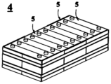
- FIG. 3 is a schematic diagram of an embodiment of the battery module of the present application.
- FIG. 4 is a schematic diagram of an embodiment of the battery pack of the present application.
- FIG. 5 is an exploded schematic view of the embodiment of the battery pack shown in FIG. 4 .
- FIG. 6 is a schematic diagram of an embodiment of a power consumption device including the secondary battery of the present application as a power source.
- Figure 7 shows the X-ray diffraction pattern (XRD) pattern of undoped LiMnPO 4 and the core of the cathode active material prepared in Example 2.
- Figure 8 shows an X-ray energy dispersive spectrum (EDS) chart of the core of the cathode active material prepared in Example 2.
- EDS X-ray energy dispersive spectrum
- Ranges disclosed herein are defined in terms of lower and upper limits. A given range is defined by selecting a lower limit and an upper limit that define the boundaries of the particular range. Ranges defined in this manner may be inclusive or exclusive of the endpoints, and may be arbitrarily combined, that is, any lower limit may be combined with any upper limit to form a range. For example, if ranges of 60-120 and 80-110 are listed for a particular parameter, understand that ranges of 60-110 and 80-120 are also expected. Furthermore, if the minimum range values 1 and 2 are listed, and if the maximum range values 3, 4, and 5 are listed, then the following ranges are all expected: 1-3, 1-4, 1-5, 2- 3, 2-4 and 2-5.
- the numerical range “a-b” represents an abbreviated representation of any combination of real numbers between a and b, where a and b are both real numbers.
- the numerical range “0-5" means that all real numbers between "0-5" have been listed in this article, and "0-5" is just an abbreviation of these numerical combinations.
- a certain parameter is an integer ⁇ 2
- the method includes steps (a) and (b), which means that the method may include steps (a) and (b) performed sequentially, or may include steps (b) and (a) performed sequentially.
- step (c) means that step (c) may be added to the method in any order.
- the method may include steps (a), (b) and (c). , may also include steps (a), (c) and (b), may also include steps (c), (a) and (b), etc.
- condition "A or B” is satisfied by any of the following conditions: A is true (or exists) and B is false (or does not exist); A is false (or does not exist) and B is true (or exists) ; Or both A and B are true (or exist).
- coating layer refers to the material layer coated on the lithium manganese phosphate core.
- the material layer can completely or partially cover the lithium manganese phosphate core.
- coating layer is used " is only for convenience of description and is not intended to limit the present invention.
- aliphatic hydrocarbon group includes alkyl, alkenyl and alkynyl groups
- heteroaliphatic hydrocarbon group means that the aliphatic hydrocarbon group contains heteroatoms (such as N, O, S, etc.).
- heteroalkyl refers to an alkyl group containing heteroatoms (such as N, O, S, etc.), such as alkoxy, alkylthio, etc.
- the inventor of the present application has repeatedly studied the effects of doping the Li site, Mn site, P site and O site of lithium manganese phosphate with various elements, and found that by doping the above four positions simultaneously with specific amounts, specific Elements, and coating the surface with a polysiloxane coating layer, can obtain significantly improved rate performance, cycle performance and high temperature stability, thereby obtaining an improved lithium manganese phosphate cathode active material.
- the first aspect of the application proposes a cathode active material with a core-shell structure, including a core and a coating layer covering at least a part of the core, wherein the core has a chemical formula Li a A x Mn 1-y By P 1- z C z O 4-n D n , the A includes one or more elements selected from Zn, Al, Na, K, Mg, Nb, Mo and W, so
- the B includes one or more elements selected from the group consisting of Ti, V, Zr, Fe, Ni, Mg, Co, Ga, Sn, Sb, Nb and Ge
- the C includes one or more elements selected from the group consisting of B (boron), S, One or more elements from Si and N
- the D includes one or more elements selected from S, F, Cl and Br
- the a is selected from the range of 0.9 to 1.1
- the x is selected from The range of 0.001 to 0.1
- the y is selected from the range of 0.001 to 0.5
- the above-mentioned limitation on the numerical range of x is not only a limitation on the stoichiometric number of each element as A, but also on the Limitation of the sum of stoichiometric numbers.
- A is two or more elements A1, A2...An
- the respective stoichiometric numbers x1, x2...xn of A1, A2...An must fall within the numerical range of x defined in this application, and x1
- the sum of , x2...xn also needs to fall within this numerical range.
- B, C and D are two or more elements
- the limitations on the numerical ranges of the stoichiometric numbers of B, C and D in this application also have the above meaning.
- the core of the cathode active material of the present application is obtained by element doping in the compound LiMnPO 4 , where A, B, C and D are respectively doped at the Li site, Mn site, P site and O site of the compound LiMnPO 4 . element.
- the performance improvement of lithium manganese phosphate is related to reducing the lattice change rate of lithium manganese phosphate and reducing surface activity during the process of deintercalating lithium. Reducing the lattice change rate can reduce the lattice constant difference between the two phases at the grain boundary, reduce the interface stress, and enhance the transport capability of Li + at the interface, thereby improving the rate performance of the cathode active material.
- the lattice change rate is reduced by Li and Mn site doping.
- Mn site doping also effectively reduces surface activity, thereby inhibiting the dissolution of manganese ions and the interface side reactions between the cathode active material and the electrolyte.
- P-site doping makes the Mn-O bond length change faster and reduces the material's small polaron migration barrier, which is beneficial to improving the electronic conductivity.
- O-site doping has a good effect on reducing interface side reactions. The doping of P and O sites also affects the dissolution of manganese ions and kinetic properties of anti-site defects.
- doping reduces the concentration of anti-site defects in the cathode active material, improves the kinetic properties and gram capacity of the cathode active material, and can also change the morphology of the particles, thereby increasing the compaction density.
- the inventor of the present application unexpectedly discovered that by simultaneously doping specific elements in specific amounts at the Li site, Mn site, P site and O site of the compound LiMnPO 4 , improved rate performance can be obtained while reducing the number of Mn and Mn sites. By dissolution of the doping elements, improved cycle performance and/or high temperature stability are obtained, and the gram capacity and compacted density of the cathode active material can also be increased.
- the A is one or more elements selected from Zn, Al, Na, K, Mg, Nb, Mo and W
- the B is selected from Ti, V, Zr, Fe, Ni, One or more elements from Mg, Co, Ga, Sn, Sb, Nb and Ge
- the C is one or more elements selected from B (boron), S, Si and N
- the D It is one or more elements selected from S, F, Cl and Br.
- the coating layer of the present application includes one or more of polysiloxane with a linear structure and polysiloxane with a cyclic structure.
- the coating layer can isolate the electrolyte and the positive active material, which is helpful to reduce the erosion of the positive active material by the electrolyte; the Si-O skeleton of the polysiloxane can remove F-containing ions in the electrolyte and relieve acidic substances Regarding the erosion of the surface of the positive active material; polysiloxane has a certain degree of hydrophobicity, which can increase the contact angle between the electrolyte and the positive electrode piece and alleviate the erosion of the surface of the positive active material by the electrolyte.
- the dissolution of Mn and Mn-site doping elements can be significantly reduced, and significantly improved cycle performance and/or high-temperature stability can be obtained.
- each of A, C and D is independently any one element within the above respective ranges, and B is at least two elements within its range.
- the A is any element selected from Mg and Nb.
- the B is at least two elements selected from Fe, Ti, V, Co and Mg, optionally Fe and one or more elements selected from Ti, V, Co and Mg.
- the C is S.
- the D is F.
- the lattice change rate during the delithiation process can be further reduced, thereby further improving the rate performance of the battery.
- the Mn doping element within the above range the electronic conductivity can be further improved and the lattice change rate can be further reduced, thereby improving the rate performance and energy density of the battery.
- the P-site doping elements within the above range the rate performance of the battery can be further improved.
- interface side reactions can be further reduced and the high-temperature stability of the battery can be improved.
- the a is selected from the range of 0.9 to 1.1, for example, 0.97, 0.977, 0.984, 0.988, 0.99, 0.991, 0.992, 0.993, 0.994, 0.995, 0.996, 0.997, 0.998, 1.01.
- the x is selected from the range of 0.001 to 0.1, for example, 0.001, 0.005.
- the y is selected from the range of 0.001 to 0.5, for example, 0.001, 0.005, 0.02, 0.05, 0.1, 0.15, 0.2, 0.25, 0.3, 0.34, 0.345, 0.349, 0.35, 0.4.
- the z is selected from the range of 0.001 to 0.1, such as 0.001, 0.005, 0.08, and 0.1.
- the n is selected from the range of 0.001 to 0.1, such as 0.001, 0.005, 0.08, and 0.1.
- x is selected from the range of 0.001 to 0.005.
- y is selected from the range of 0.01 to 0.5, optionally from the range of 0.25 to 0.5.
- z is selected from the range of 0.001 to 0.005.
- n is selected from the range of 0.001 to 0.005.
- the dynamic performance of the cathode active material can be further improved.
- the y value within the above range the gram capacity and rate performance of the cathode active material can be further improved.
- the z value within the above range the rate performance of the battery can be further improved.
- the n value within the above range the high-temperature stability of the battery can be further improved.
- the positive active material core satisfies (1-y): y is in the range of 1 to 4, optionally in the range of 1.5 to 3, and a:x is in the range of 9 to 1100, optionally The land is in the range of 190-998.
- y represents the sum of stoichiometric numbers of Mn-site doping elements.
- the polymer includes at least one structural unit represented by Formula 1,
- R 1 and R 2 each independently represent H or at least one of the group consisting of the following functional groups: -COOH, -OH, -SH, -CN, -SCN, amino, phosphate group, carboxylate group, amide group, aldehyde group, sulfonyl group, polyether segment, C1 ⁇ C20 aliphatic hydrocarbon group, C1 ⁇ C20 halogenated aliphatic hydrocarbon group, C1 ⁇ C20 heteroaliphatic hydrocarbon group, C1 ⁇ C20 halogenated heteroaliphatic hydrocarbon group, C6 ⁇ C20 aromatic hydrocarbon group, C6 ⁇ C20 halogenated aromatic hydrocarbon group, C2 ⁇ C20 heteroaromatic hydrocarbon group, C2 ⁇ C20 halogenated heteroaromatic hydrocarbon group.
- R 1 and R 2 each independently represent H or at least one of the group consisting of the following functional groups: amino group, phosphate group, polyether segment, C1 to C8 alkyl group, C1 to C8 haloalkyl group, C1 ⁇ C8 heteroalkyl, C1 ⁇ C8 haloheteroalkyl, C2 ⁇ C8 alkenyl, C2 ⁇ C8 haloalkenyl.
- These functional groups can combine with acidic substances in the electrolyte to alleviate the erosion of the surface of the positive active material by the acidic substances in the electrolyte.
- these functional groups have electron-withdrawing properties, the Si in the Si-O skeleton of the polysiloxane can be made more electron-deficient, which can further enhance the affinity with F ions in the electrolyte and further alleviate acidic substances in the electrolyte.
- the dissolution of Mn and Mn-site doping elements is reduced, thereby significantly improving the cycle performance and/or high temperature stability of the battery.
- the linear-structured polysiloxane may further include an end-capping group.
- the end-capping group includes at least one of the following functional groups: polyether, C1-C8 alkyl, C1-C8 haloalkyl, C1-C8 heteroalkyl, C1-C8 haloheteroalkyl.
- the polysiloxanes with linear structures include, but are not limited to, polydimethylsiloxane, polydiethylsiloxane, polymethylethylsiloxane, and polymethylvinylsiloxane.
- polyphenylmethylsiloxane polymethylhydrogensiloxane, carboxyl functionalized polysiloxane, epoxy-terminated polysiloxane, methoxy-terminated polydimethylsiloxane, hydroxypropyl Base-terminated polydimethylsiloxane, polymethylchloropropylsiloxane, hydroxyl-terminated polydimethylsiloxane, polymethyltrifluoropropylsiloxane, perfluorooctylmethylpolysiloxane Oxane, aminoethylaminopropyl dimethicone, terminal polyether polydimethylsiloxane, side chain aminopropyl polysiloxane, aminopropyl terminated polydimethylsiloxane One or more of alkane, side chain phosphate grafted polydimethylsiloxane, and side chain polyether grafted polydimethylsiloxane.
- the polysiloxane with linear structure includes polymethyltrifluoropropylsiloxane, aminoethylaminopropylpolydimethylsiloxane, and side chain phosphate grafted polydimethylsiloxane.
- the cyclic structure polysiloxane includes but is not limited to 1,3,5,7-octamethylcyclotetrasiloxane, 1,3,5,7-tetrahydro-1,3,5 ,7-tetramethylcyclotetrasiloxane, cyclopentamethicone, 2,4,6,8-tetramethylcyclotetrasiloxane, 2,4,6,8-tetramethyl -2,4,6,8-tetravinylcyclotetrasiloxane, cyclic polymethylvinylsiloxane, hexadecylmethylcyclooctasiloxane, tetradecamethylcycloheptasiloxane, cyclic One or more polydimethylsiloxanes.
- the polymer is selected from linear structured polysiloxanes.
- the electrons in the ring of polysiloxane with a cyclic structure have a certain degree of delocalization. Therefore, compared with polysiloxane with a linear structure, its Si-O skeleton has less affinity for electron-rich F-containing ions. Smaller, then the removal rate of F ions in the electrolyte is slightly lower, the effect of reducing the dissolution of Mn and Mn-site doping elements is slightly weaker, and the improvement effect on battery cycle performance is slightly less.
- the number average molecular weight of the polymer is below 300,000, for example, it can be 400 to 300,000, 400 to 200,000, 400 to 100,000, 400 to 80,000, 400 to 50,000, 400 to 20,000, 400 to 10,000, 1000 to 100000, 1000 to 50000, 1000 to 20000, 1000 to 10000.
- the number average molecular weight of a polymer can be determined by methods known in the art, such as gel permeation chromatography (GPC).
- the testing instrument can use PL-GPC220 high temperature gel permeation chromatograph.
- polymer can be either an oligomer or a polymer, which is not limited in this application.
- the cathode active material can also achieve both good dynamic performance and high temperature stability. And can effectively avoid the following situations: the number average molecular weight of the polymer is too small, and it cannot have an obvious coating modification effect on the core; the number average molecular weight of the polymer is too large, and its hydrophobicity may be strong, which may affect the battery dynamic properties, and may also lead to poor coating modification effects.
- the mass percentage of polar functional groups in the polysiloxane is ⁇ , 0 ⁇ 50%. Alternatively, 5% ⁇ 30%.
- “mass percentage of polar functional groups in polysiloxane” refers to the mass proportion of polar functional groups in R 1 , R 2 and end-capping groups in polysiloxane.
- ⁇ represents the mass fraction of these polar functional groups in polysiloxane; when the above polar functional groups are not directly connected to silicon atoms, ⁇ represents the sum of the polar functional groups and their The sum of the mass fractions of directly connected divalent to tetravalent methyl groups (such as -CH 2 , -CH-, -C-, etc.) in polysiloxane, where "divalent to tetravalent methyl" means the same as the polar
- divalent to tetravalent methyl groups such as -CH 2 , -CH-, -C-, etc.
- ⁇ refers to the mass percentage of -CF 3 , excluding the ethylene group; taking polymethylchloropropylsiloxane as an example, ⁇ is Refers to the mass percentage of -CH 2 Cl, excluding the ethylene group; taking hydroxypropyl-terminated polydimethylsiloxane as an example, ⁇ refers to the mass percentage of -CH 2 OH.
- the mass percentage of polar functional groups in polysiloxane can be determined by methods known in the art, such as titration (such as acid-base titration, redox titration, precipitation titration), infrared spectroscopy, and nuclear magnetic resonance. Determined by spectroscopy.
- the coating amount of the coating layer is 0.01% to 10% by weight, optionally 0.1% to 5% by weight, and further 0.1% to 2% by weight, based on the core. Weight scale.
- the coating amount of the coating layer is within a suitable range, the coating modification effect on the core is better. And can effectively avoid the following situations: when the coating amount of the coating layer is too low, its coating modification effect on the core may not be obvious; when the coating amount of the coating layer is too high, the battery impedance may increase, which may Affects the rate performance and cycle performance of the battery.
- the cathode active material may further include a carbon layer between the core and the cladding layer. Thereby, the conductivity of the positive electrode active material can be improved.
- the cathode active material has a lattice change rate of 8% or less, optionally, a lattice change rate of 4% or less.
- a lattice change rate can be measured by methods known in the art, such as X-ray diffraction (XRD).
- the positive electrode active material has a Li/Mn anti-site defect concentration of 2% or less, and optionally, the Li/Mn anti-site defect concentration is 0.5% or less.
- the so-called Li/Mn antisite defect refers to the interchange of positions between Li + and Mn 2+ in the LiMnPO 4 lattice.
- the Li/Mn anti-site defect concentration refers to the percentage of Li + exchanged with Mn 2+ in the positive active material to the total amount of Li + . Mn 2+ with anti-site defects will hinder the transport of Li + .
- the Li/Mn anti-site defect concentration can be measured by methods known in the art, such as XRD.
- the surface oxygen valence state of the cathode active material is -1.82 or less, optionally -1.89 to -1.98.
- the interface side reactions between the positive electrode active material and the electrolyte can be alleviated, thereby improving the cycle performance and high-temperature stability of the battery.
- Surface oxygen valence state can be measured by methods known in the art, such as by electron energy loss spectroscopy (EELS).
- the positive active material has a compacted density of 2.0 g/cm or more at 3 T (tons), optionally 2.2 g/cm or more.
- the compacted density can be measured according to GB/T24533-2009.
- the second aspect of the present application relates to a method for preparing the cathode active material of the first aspect of the present application, which includes the following steps:
- step (3) Transfer the slurry obtained in step (2) to spray drying equipment for spray drying and granulation to obtain particles;
- the core and the polymer obtained in step (4) are coated by dry coating or wet coating to obtain a positive electrode active material.
- the polymer includes polysiloxane with a linear structure and polysiloxane with a cyclic structure. One or more polysiloxanes.
- the source of element A is selected from at least one of elemental elements, oxides, phosphates, oxalates, carbonates and sulfates of element A
- the source of element B is selected from elemental elements of element B
- the source of element C is selected from at least one of sulfate, borate, nitrate and silicate of element C
- the source of element D is selected from at least one of elemental elements and ammonium salts of element D.
- the acid is selected from one or more of hydrochloric acid, sulfuric acid, nitric acid, phosphoric acid, organic acids such as oxalic acid, etc., for example, it can be oxalic acid.
- the acid is a dilute acid with a concentration of 60% by weight or less.
- the manganese source can be a manganese-containing substance known in the art that can be used to prepare lithium manganese phosphate.
- the manganese source can be selected from the group consisting of elemental manganese, manganese dioxide, manganese phosphate, manganese oxalate, and carbonate. One or a combination of manganese.
- the lithium source can be a lithium-containing substance known in the art that can be used to prepare lithium manganese phosphate.
- the lithium source can be selected from the group consisting of lithium carbonate, lithium hydroxide, lithium phosphate, and lithium dihydrogen phosphate. one of them or a combination of them.
- the phosphorus source can be a phosphorus-containing material known in the art that can be used to prepare lithium manganese phosphate.
- the phosphorus source can be selected from the group consisting of diammonium hydrogen phosphate, ammonium dihydrogen phosphate, ammonium phosphate, and phosphoric acid. one of them or a combination of them.
- the added amounts of the respective sources of elements A, B, C, and D depend on the target doping amount, and the ratio of the amounts of lithium source, manganese source, and phosphorus source conforms to the stoichiometric ratio.
- the solvents described in step (1) and step (2) can each independently be a solvent commonly used by those skilled in the art in the preparation of manganese salts and lithium manganese phosphates.
- they can each be independently selected. From at least one of ethanol, water (such as deionized water), etc.
- the stirring of step (1) is performed at a temperature in the range of 60-120°C. In some embodiments, the stirring of step (1) is performed at a stirring rate of 200-800 rpm, or 300-800 rpm, or 400-800 rpm. In some embodiments, the stirring of step (1) is performed for 6-12 hours. In some embodiments, the grinding and mixing of step (2) is performed for 8-15 hours.
- the doping elements can be evenly distributed and the crystallinity of the material after sintering is higher, thereby improving the gram capacity and rate performance of the cathode active material.
- the filter cake may be washed before drying the filter cake in step (1).
- the drying in step (1) can be performed by methods and conditions known to those skilled in the art.
- the drying temperature can be in the range of 120-300°C.
- the filter cake can be ground into particles after drying, for example, until the median diameter Dv 50 of the particles is in the range of 50-200 nm.
- the median particle diameter Dv 50 refers to the particle diameter corresponding to when the cumulative volume distribution percentage of the material reaches 50%.
- the median particle diameter Dv 50 of the material can be determined using laser diffraction particle size analysis. For example, refer to the standard GB/T 19077-2016 and use a laser particle size analyzer (such as Malvern Master Size 3000) for measurement.
- a carbon source is also added to the reaction vessel for grinding and mixing.
- the method can obtain a cathode active material with carbon coated between the core and the coating layer.
- the carbon source includes one or a combination of one or more of starch, sucrose, glucose, polyvinyl alcohol, polyethylene glycol, and citric acid.
- the amount of the carbon source relative to the amount of the lithium source is usually in the range of a molar ratio of 0.1% to 5%.
- the grinding can be performed by suitable grinding methods known in the art, for example, by sand grinding.
- the temperature and time for spray drying in step (3) can be conventional temperatures and times for spray drying in the art, for example, at 100-300°C for 1-6 hours.
- sintering in step (4) is performed at a temperature in the range of 600-900°C for 6-14 hours.
- the crystallinity of the cathode active material can be controlled, reducing the dissolution of Mn and Mn-site doping elements after cycles, thereby improving the high-temperature stability and cycle performance of the battery.
- sintering in step (4) is performed under a protective atmosphere, which may be nitrogen, inert gas, hydrogen or a mixture thereof.
- dry coating to prepare the cathode active material in step (5) may include mixing the core and the polymer uniformly using a mixer to form a mixed powder, and then sintering in a sintering furnace in a nitrogen or inert gas atmosphere. get. Sintering can be carried out at a temperature range of 200-300°C for 4-10 hours. Optionally sintered at about 200°C, about 250°C, or about 300°C for about 4 hours, about 6 hours, about 8 hours, or about 10 hours. Optionally, the sintering temperature and sintering time may be within any range of any of the above values.
- the sintering temperature and time within the above range, the following situations can be effectively avoided: when the sintering temperature is too low or the sintering time is too short, the bonding between the cladding layer and the core may not be strong enough; the sintering temperature is too high or the sintering time is too long. Over time, the polymer may be carbonized and cannot remove F ions from the electrolyte.
- preparing the cathode active material by wet coating in step (5) may be to dissolve the polymer in a solvent to form a coating liquid, then add the core to it and stir evenly to form a mixed slurry, and then add the mixed slurry Place it in a wet bag machine and dry it while stirring in a nitrogen or inert gas atmosphere. Drying can be at a temperature of 100°C to 200°C, optionally 110°C to 190°C, more optionally 120°C to 180°C, even more optionally 120°C to 170°C, most optionally 120°C to 160°C Within the range, the drying time can be 3-9 hours, optionally 4-8 hours, more optionally 5-7 hours, and the most optional is about 6 hours.
- a third aspect of the present application provides a positive electrode sheet, which includes a positive electrode current collector and a positive electrode film layer disposed on at least one surface of the positive electrode current collector.
- the positive electrode film layer includes the positive electrode active material of the first aspect of the present application or is formed by the positive electrode active material of the present application.
- the cathode active material prepared by the method of the second aspect is applied, and the content of the cathode active material in the cathode film layer is more than 10% by weight, based on the total weight of the cathode film layer.
- the positive electrode current collector has two surfaces opposite in its thickness direction, and the positive electrode film layer is disposed on any one or both of the two opposite surfaces of the positive electrode current collector.
- the content of the cathode active material in the cathode film layer is 95-99.5% by weight, based on the total weight of the cathode film layer.
- the content of the cathode active material is within the above range, it is beneficial to give full play to the advantages of the cathode active material of the present application.
- the cathode film layer does not exclude other cathode active materials other than the cathode active material of the first aspect of the application or the cathode active material prepared by the method of the second aspect of the application.
- the cathode film layer may also include lithium transition metal oxide. At least one of its modified compounds.
- the other cathode active materials may include lithium cobalt oxide, lithium nickel oxide, lithium manganese oxide, lithium nickel cobalt oxide, lithium manganese cobalt oxide, lithium nickel manganese oxide, lithium nickel cobalt manganese oxide , at least one of lithium nickel cobalt aluminum oxide and its modified compounds.
- the positive electrode film layer optionally further includes a positive electrode conductive agent.
- a positive electrode conductive agent includes superconducting carbon, conductive graphite, acetylene black, carbon black, Ketjen black, carbon dots, carbon nanotubes, and graphene. , at least one of carbon nanofibers.
- the positive electrode film layer optionally further includes a positive electrode binder.
- a positive electrode binder may include polyvinylidene fluoride (PVDF), polytetrafluoroethylene (PTFE), vinylidene fluoride-tetrafluoroethylene -At least one of propylene terpolymer, vinylidene fluoride-hexafluoropropylene-tetrafluoroethylene terpolymer, tetrafluoroethylene-hexafluoropropylene copolymer, and fluorine-containing acrylate resin.
- the positive electrode current collector may be a metal foil or a composite current collector.
- a metal foil aluminum foil can be used.
- the composite current collector may include a polymer material base layer and a metal material layer formed on at least one surface of the polymer material base layer.
- the metal material may be selected from at least one of aluminum, aluminum alloy, nickel, nickel alloy, titanium, titanium alloy, silver, and silver alloy.
- the polymer material base layer can be selected from the group consisting of polypropylene (PP), polyethylene terephthalate (PET), polybutylene terephthalate (PBT), polystyrene (PS), poly Ethylene (PE), etc.
- the solid-liquid contact angle between the positive electrode film layer and the non-aqueous organic solvent is between 3° and 90°, optionally between 3° and 60°, further between 10° and 10°. between 30°.
- the contact angle is within a suitable range, the battery can simultaneously achieve high energy density, good rate performance, cycle performance and high temperature stability. And can effectively avoid the following situations: if the contact angle is too small, the polymer may not be able to achieve a good coating modification effect, and its effect of reducing the dissolution of Mn and Mn-site doping elements may not be obvious; when the contact angle is too large, It may cause the electrolyte wettability of the positive electrode film to deteriorate, affecting the rate performance and cycle performance of the battery.
- the solid-liquid contact angle between the positive electrode film layer and the non-aqueous organic solvent has a well-known meaning in the art, and can be tested using methods known in the art. For example, it can be measured with reference to GBT30693-2014.
- An exemplary test method includes the following steps: at room temperature, droplets of non-aqueous organic solvent are placed on the surface of the positive electrode piece, and the contact angle within 60 seconds is measured using a contact angle measuring instrument.
- the testing instrument can be the LSA200 optical contact angle measuring instrument from the German LAUDAS Scientific company.
- the non-aqueous organic solvent may be a non-aqueous organic solvent that is well known in the art and is used in non-aqueous electrolyte solutions for secondary batteries. Alternatively, the non-aqueous organic solvent may be ethylene carbonate (EC).
- the porosity of the positive electrode film layer is 15% to 50%, optionally 20% to 40%.
- the battery can achieve both high energy density and good rate performance, cycle performance and high-temperature stability. And can effectively avoid the following situations: if the porosity is too small, the electrolyte wettability of the positive electrode film layer may become poor, affecting the rate performance and cycle performance of the battery; if the porosity is too large, the overall energy density of the battery may be affected .
- the porosity of the positive electrode film layer has a well-known meaning in the art, and can be tested using methods known in the art. For example, it can be measured with reference to GB/T 24586-2009.
- the positive electrode film layer is usually formed by coating the positive electrode slurry on the positive electrode current collector, drying, and cold pressing.
- the positive electrode slurry is usually formed by dispersing the positive electrode active material, optional conductive agent, optional binder and any other components in a solvent and stirring evenly.
- the solvent may be N-methylpyrrolidone (NMP), but is not limited thereto.
- each positive electrode film layer (such as contact angle, porosity, etc.) given in this application refer to the parameters of the positive electrode film layer on one side of the positive electrode current collector.
- the positive electrode film layer is disposed on both sides of the positive electrode current collector, if the parameters of the positive electrode film layer on either side meet the requirements of this application, it is deemed to fall within the protection scope of this application.
- the above-mentioned parameter tests for the positive electrode film layer can be performed by sampling and testing during the preparation process of the electrode sheet or battery, or by sampling and testing from the prepared battery.
- the sampling can be carried out according to the following steps: discharge the battery (for safety reasons, the battery is generally in a fully discharged state); disassemble the battery and take out the positive electrode sheet, use dimethyl carbonate (DMC) to soak the positive electrode sheet for a certain period of time (for example, 2-10 hours); then take out the positive electrode sheet and dry it at a certain temperature and time (for example, 60°C, 4 hours), and dry Finally, the positive electrode piece is taken out. At this time, samples can be taken from the dried positive electrode piece to test various parameters related to the positive electrode film layer mentioned above in this application.
- DMC dimethyl carbonate
- the fourth aspect of the present application provides a secondary battery, which includes the positive electrode sheet of the third aspect of the present application.
- Secondary batteries also known as rechargeable batteries or storage batteries, refer to batteries that can be recharged to activate active materials and continue to be used after the battery is discharged.
- a secondary battery includes an electrode assembly and an electrolyte.
- the electrode assembly includes a positive electrode plate, a negative electrode plate and a separator.
- the isolation film is placed between the positive electrode piece and the negative electrode piece. It mainly prevents the positive and negative electrodes from short-circuiting and allows active ions to pass through.
- the electrolyte plays a role in conducting active ions between the positive electrode piece and the negative electrode piece.
- the positive electrode sheet used in the secondary battery of the present application is the positive electrode sheet described in any embodiment of the third aspect of the present application.
- the negative electrode sheet includes a negative electrode current collector and a negative electrode film layer disposed on at least one surface of the negative electrode current collector and including a negative electrode active material.
- the negative electrode current collector has two surfaces opposite in its thickness direction, and the negative electrode film layer is disposed on any one or both of the two opposite surfaces of the negative electrode current collector.
- the negative active material may be a negative active material known in the art for secondary batteries.
- the negative active material includes but is not limited to at least one of natural graphite, artificial graphite, soft carbon, hard carbon, silicon-based materials, tin-based materials, and lithium titanate.
- the silicon-based material may include at least one of elemental silicon, silicon oxide, silicon-carbon composite, silicon-nitride composite, and silicon alloy material.
- the tin-based material may include at least one of elemental tin, tin oxide, and tin alloy materials.
- the present application is not limited to these materials, and other conventionally known materials that can be used as negative electrode active materials for secondary batteries can also be used. Only one type of these negative electrode active materials may be used alone, or two or more types may be used in combination.
- the negative electrode film layer optionally further includes a negative electrode conductive agent.
- a negative electrode conductive agent may include superconducting carbon, conductive graphite, acetylene black, carbon black, Ketjen black, carbon dots, carbon nanotubes, graphite At least one of alkenes and carbon nanofibers.
- the negative electrode film layer optionally further includes a negative electrode binder.
- a negative electrode binder may include styrene-butadiene rubber (SBR), water-soluble unsaturated resin SR-1B, water-based acrylic resin (for example, At least one of polyacrylic acid PAA, polymethacrylic acid PMAA, polyacrylic acid sodium PAAS), polyacrylamide (PAM), polyvinyl alcohol (PVA), sodium alginate (SA), carboxymethyl chitosan (CMCS) kind.
- SBR styrene-butadiene rubber
- SR-1B water-soluble unsaturated resin
- acrylic resin for example, At least one of polyacrylic acid PAA, polymethacrylic acid PMAA, polyacrylic acid sodium PAAS), polyacrylamide (PAM), polyvinyl alcohol (PVA), sodium alginate (SA), carboxymethyl chitosan (CMCS) kind.
- the negative electrode film layer optionally further includes other additives.
- other auxiliaries may include thickeners, such as sodium carboxymethylcellulose (CMC), PTC thermistor materials, and the like.
- the negative electrode current collector may be a metal foil or a composite current collector.
- the metal foil copper foil can be used.
- the composite current collector may include a polymer material base layer and a metal material layer formed on at least one surface of the polymer material base layer.
- the metal material may be selected from at least one of copper, copper alloy, nickel, nickel alloy, titanium, titanium alloy, silver, and silver alloy.
- the polymer material base layer can be selected from the group consisting of polypropylene (PP), polyethylene terephthalate (PET), polybutylene terephthalate (PBT), polystyrene (PS), poly Ethylene (PE), etc.
- the negative electrode film layer is usually formed by coating the negative electrode slurry on the negative electrode current collector, drying, and cold pressing.
- the negative electrode slurry is usually formed by dispersing the negative electrode active material, optional conductive agent, optional binder, and other optional additives in a solvent and stirring evenly.
- the solvent may be N-methylpyrrolidone (NMP) or deionized water, but is not limited thereto.
- the negative electrode plate does not exclude other additional functional layers in addition to the negative electrode film layer.
- the negative electrode sheet described in the present application further includes a conductive undercoat layer (for example, made of Conductive agent and adhesive).
- the negative electrode sheet described in this application further includes a protective layer covering the surface of the negative electrode film layer.
- the electrolyte may be selected from at least one of a solid electrolyte and a liquid electrolyte (ie, electrolyte).
- the electrolyte is an electrolyte solution that includes an electrolyte salt and a solvent.
- the electrolyte salt may include lithium hexafluorophosphate (LiPF 6 ), lithium tetrafluoroborate (LiBF 4 ), lithium perchlorate (LiClO 4 ), lithium hexafluoroarsenate (LiAsF 6 ), bis Lithium fluorosulfonyl imide (LiFSI), lithium bistrifluoromethanesulfonyl imide (LiTFSI), lithium trifluoromethanesulfonate (LiTFS), lithium difluoromethanesulfonyl borate (LiDFOB), lithium dioxalatoborate (LiBOB), At least one of lithium difluorophosphate (LiPO 2 F 2 ), lithium difluorodioxalate phosphate (LiDFOP), and lithium tetrafluorooxalate
- the solvent may include ethylene carbonate (EC), propylene carbonate (PC), ethyl methyl carbonate (EMC), diethyl carbonate (DEC), dimethyl carbonate ( DMC), dipropyl carbonate (DPC), methylpropyl carbonate (MPC), ethylpropyl carbonate (EPC), butylene carbonate (BC), fluoroethylene carbonate (FEC), methyl formate (MF) , methyl acetate (MA), ethyl acetate (EA), propyl acetate (PA), methyl propionate (MP), ethyl propionate (EP), propyl propionate (PP), methyl butyrate At least one of (MB), ethyl butyrate (EB), 1,4-butyrolactone (GBL), sulfolane (SF), dimethyl sulfone (MSM), methyl ethyl
- additives are optionally included in the electrolyte.
- the additives may include negative electrode film-forming additives, positive electrode film-forming additives, and may also include additives that can improve certain properties of the battery, such as additives that improve battery overcharge performance, additives that improve battery high-temperature performance, and additives that improve battery performance. Additives for low temperature power performance, etc.
- Secondary batteries using electrolytes and some secondary batteries using solid electrolytes also include a separator.
- the isolation film is disposed between the positive electrode piece and the negative electrode piece, and mainly functions to prevent the positive and negative electrodes from short-circuiting, and at the same time, allows active ions to pass through.
- the material of the isolation membrane may include at least one of glass fiber, non-woven fabric, polyethylene, polypropylene and polyvinylidene fluoride.
- the isolation film may be a single-layer film or a multi-layer composite film. When the isolation film is a multi-layer composite film, the materials of each layer may be the same or different.
- the positive electrode piece, the isolation film and the negative electrode piece can be made into an electrode assembly through a winding process or a lamination process.
- the secondary battery may include an outer packaging.
- the outer packaging can be used to package the above-mentioned electrode assembly and electrolyte.
- the outer packaging of the secondary battery may be a hard shell, such as a hard plastic shell, an aluminum shell, a steel shell, etc.
- the outer packaging of the secondary battery may also be a soft bag, such as a bag-type soft bag.
- the soft bag may be made of plastic, such as at least one of polypropylene (PP), polybutylene terephthalate (PBT), polybutylene succinate (PBS), and the like.
- This application has no particular limitation on the shape of the secondary battery, which can be cylindrical, square or any other shape. As shown in FIG. 1 , a square-structured secondary battery 5 is shown as an example.
- the outer package may include a housing 51 and a cover 53 .
- the housing 51 may include a bottom plate and side plates connected to the bottom plate, and the bottom plate and the side plates enclose to form a receiving cavity.
- the housing 51 has an opening communicating with the accommodation cavity, and the cover plate 53 is used to cover the opening to close the accommodation cavity.
- the positive electrode piece, the negative electrode piece and the separator film can be formed into the electrode assembly 52 through a winding process or a lamination process.
- the electrode assembly 52 is packaged in the containing cavity.
- the electrolyte soaks into the electrode assembly 52 .
- the number of electrode assemblies 52 contained in the secondary battery 5 can be one or several, and can be adjusted according to needs.
- the positive electrode sheet, the separator, the negative electrode sheet, and the electrolyte may be assembled to form a secondary battery.
- the positive electrode sheet, isolation film, and negative electrode sheet can be formed into an electrode assembly through a winding process or a lamination process.
- the electrode assembly is placed in an outer package, dried, and then injected with electrolyte. After vacuum packaging, standing, and Through processes such as formation and shaping, secondary batteries are obtained.
- the secondary batteries according to the present application can be assembled into a battery module.
- the number of secondary batteries contained in the battery module can be multiple, and the specific number can be adjusted according to the application and capacity of the battery module.
- FIG. 3 is a schematic diagram of the battery module 4 as an example.
- a plurality of secondary batteries 5 may be arranged in sequence along the length direction of the battery module 4 .
- the plurality of secondary batteries 5 can be fixed by fasteners.
- the battery module 4 may further include a housing having a receiving space in which a plurality of secondary batteries 5 are received.
- the above-mentioned battery modules can also be assembled into a battery pack, and the number of battery modules contained in the battery pack can be adjusted according to the application and capacity of the battery pack.
- the battery pack 1 may include a battery box and a plurality of battery modules 4 arranged in the battery box.
- the battery box includes an upper box 2 and a lower box 3 .
- the upper box 2 is used to cover the lower box 3 and form a closed space for accommodating the battery module 4 .
- Multiple battery modules 4 can be arranged in the battery box in any manner.
- a fifth aspect of the present application provides an electrical device, which includes at least one of a secondary battery, a battery module, or a battery pack of the present application.
- the secondary battery, battery module or battery pack may be used as a power source for the electrical device or as an energy storage unit for the electrical device.
- the electrical device may be, but is not limited to, mobile devices (such as mobile phones, laptops, etc.), electric vehicles (such as pure electric vehicles, hybrid electric vehicles, plug-in hybrid electric vehicles, electric bicycles, electric scooters, electric Golf carts, electric trucks, etc.), electric trains, ships and satellites, energy storage systems, etc.
- the power-consuming device can select a secondary battery, a battery module or a battery pack according to its usage requirements.
- FIG. 6 is a schematic diagram of an electrical device as an example.
- the electric device is a pure electric vehicle, a hybrid electric vehicle, a plug-in hybrid electric vehicle, etc.
- battery packs or battery modules can be used.
- the power-consuming device may be a mobile phone, a tablet computer, a laptop computer, etc.
- the electrical device is usually required to be light and thin, and secondary batteries can be used as power sources.
- Preparation of doped manganese oxalate add 1.3 mol of MnSO 4 . H 2 O, 0.7mol FeSO 4 . The H 2 O was mixed thoroughly in the mixer for 6 hours. The mixture was transferred to the reaction kettle, and 10 L of deionized water and 2 mol of oxalic acid dihydrate (calculated as oxalic acid) were added. The reaction kettle was heated to 80° C. and stirred at a rotation speed of 600 rpm for 6 hours. The reaction was terminated (no bubbles were generated), and an Fe-doped manganese oxalate suspension was obtained. The suspension is then filtered, and the filter cake is dried at 120° C. and then ground to obtain Fe-doped manganese oxalate particles with a median particle size Dv 50 of about 100 nm.
- Preparation of core Take 1 mol of the above manganese oxalate particles, 0.497 mol of lithium carbonate, 0.001 mol of Mo(SO 4 ) 3 , an 85% phosphoric acid aqueous solution containing 0.999 mol of phosphoric acid, 0.001 mol of H 4 SiO 4 , and 0.0005 mol of NH. 4 HF 2 and 0.005mol sucrose were added to 20L deionized water. The mixture was transferred to a sand mill and thoroughly ground and stirred for 10 hours to obtain a slurry. Transfer the slurry to spray drying equipment for spray drying and granulation. Set the drying temperature to 250°C and dry for 4 hours to obtain granules.
- Coating of the coating layer Dissolve aminoethylaminopropyl polydimethylsiloxane in xylene to form a coating liquid, then add the prepared core to it and stir evenly to form a mixed slurry, and then add the mixed slurry Place it in a wet wrapping machine and dry it at 120°C for 4 hours in a nitrogen atmosphere to obtain a positive electrode active material.
- the mass percentage of the polar functional groups (i.e. -CH 2 NH 2 and -CH 2 NH-) of aminoethylaminopropyl polydimethylsiloxane is 12%, the number average molecular weight is 3700, and the coating amount is 1% by weight, based on the weight of the core prepared.
- the above-mentioned positive electrode active material, polyvinylidene fluoride (PVDF), and acetylene black were added to N-methylpyrrolidone (NMP) in a weight ratio of 90:5:5, and stirred in a drying room to form a slurry.
- NMP N-methylpyrrolidone
- the above slurry is coated on aluminum foil, dried and cold pressed to form a positive electrode sheet.
- the coating amount is 0.2g/cm 2 and the compacted density is 2.0g/cm 3 .
- a lithium sheet is used as the negative electrode, and a solution of 1 mol/L LiPF 6 in ethylene carbonate (EC), diethyl carbonate (DEC) and dimethyl carbonate (DMC) with a volume ratio of 1:1:1 is used as the electrolyte.
- EC ethylene carbonate
- DEC diethyl carbonate
- DMC dimethyl carbonate
- PE Polyethylene
- the isolation film is used as the isolation film, and the positive electrode piece, isolation film, and negative electrode piece are stacked in order so that the isolation film is between the positive and negative electrodes for isolation, and the electrode assembly is obtained by winding.
- aminoethylaminopropyl polydimethylsiloxane was replaced by polymethyltrifluoropropylsiloxane (the polar functional group is -CF 3 , mass The percentage content is 44%, the number average molecular weight is 1400), the side chain phosphate grafted polydimethylsiloxane (the polar functional group is a phosphate ester group, the mass percentage content is 1.42%, the number average molecular weight is 15600) , polymethylchloropropylsiloxane (polar functional group is -CH 2 Cl, mass percentage is 30.2%, number average molecular weight is 2500), polydimethylsiloxane (polar functional group mass percentage Approximately 0%, number average molecular weight is 1200), terminal polyether polydimethylsiloxane (polar functional group is polyether segment, mass percentage is 10%, number average molecular weight is 2110), polymethylmethacrylate Vinylsiloxan
- aminoethylaminopropyl polydimethylsiloxane is replaced by polydimethylsiloxane with number average molecular weights of 400, 10000, 50000, 80000, 100000, 300000, and 400000 respectively. Except for the base siloxane, the rest was the same as in Example 1.
- Preparation of manganese oxalate add 1 mol of MnSO 4 . H 2 O was added to the reaction kettle, and 10 L of deionized water and 1 mol of oxalic acid dihydrate (calculated as oxalic acid) were added. The reaction kettle was heated to 80°C and stirred at 600 rpm for 6 hours. The reaction was terminated (no bubbles were generated), and a manganese oxalate suspension was obtained. The suspension is then filtered, and the filter cake is dried at 120° C. and then ground to obtain manganese oxalate particles with a median particle size Dv 50 of 50-200 nm.
- Preparation of lithium manganese phosphate Take 1 mol of the above manganese oxalate particles, 0.5 mol of lithium carbonate, an 85% phosphoric acid aqueous solution containing 1 mol of phosphoric acid, and 0.005 mol of sucrose and add them to 20 L of deionized water. The mixture was transferred to a sand mill and thoroughly ground and stirred for 10 hours to obtain a slurry. Transfer the slurry to spray drying equipment for spray drying and granulation. Set the drying temperature to 250°C and dry for 4 hours to obtain granules. In a protective atmosphere of nitrogen (90 volume %) + hydrogen (10 volume %), the above powder was sintered at 700° C. for 10 hours to obtain carbon-coated LiMnPO 4 .
- the positive active material sample is prepared into a buckle, and the buckle is charged at a small rate of 0.05C until the current is reduced to 0.01C. Then take out the positive electrode piece from the battery and soak it in DMC for 8 hours. Then it is dried, scraped into powder, and particles with a particle size less than 500nm are screened out. Take a sample and calculate its lattice constant v1 in the same way as the above-mentioned test of the fresh sample. (v0-v1)/v0 ⁇ 100% is shown in the table as the lattice change rate before and after complete deintercalation of lithium.
- Porosity P [(V2-V1)/V2] ⁇ 100%.
- V1 (cm 3 ) represents the true volume, which can be measured by using an inert gas with a small molecular diameter (such as helium) through the substitution method, combining Archimedes' principle and Bohr's law.
- V2 (cm 3 ) represents the apparent volume
- V2 S ⁇ H ⁇ A
- S (cm 2 ) represents the area
- H (cm) represents the thickness
- A represents the number of samples.
- the battery of the embodiment always maintained an SOC of more than 99% during the test process until the end of storage.
- ACSTEM Spherical aberration electron microscopy
- Table 1 shows the positive electrode active material compositions of Examples 1-11 and Comparative Examples 1-9.
- Table 2 shows the cathode active material compositions of Examples 12-27.
- Table 3 shows the performance data of the positive active materials, positive electrode sheets, buckled batteries or full batteries of Examples 1-11 and Comparative Examples 1-9 measured according to the above performance test method.
- Table 4 shows the performance data measured according to the above performance testing method for the positive active materials, positive electrode sheets, buckled electricity or full electricity of Examples 12-27.
- Example 8 Li 0.993 Nb 0.001 Mn 0.65 Fe 0.34 V 0.005 Ni 0.005 P 0.999 S 0.001 O 3.999 F 0.001 1% Aminoethylaminopropyl Dimethicone
- Example 9 Li 0.991 Nb 0.001 Mn 0.65 Fe 0.349 Ti 0.001 P 0.999 S 0.001 O 3.999 Cl 0.001 1% Aminoethylaminopropyl Dimethicone
- Example 10 Li 0.995 Nb 0.001 Mn 0.65 Fe 0.34 V 0.005 Mg 0.005 P 0.999 Si 0.001 O 3.999 Br 0.001 1% Aminoethylaminopropyl Dimethicone
- Example 11 Li 0.998 Mg 0.001 Mn 0.65 Fe 0.345 V 0.005 P 0.999 Si 0.001 O 3.999 Br 0.001 1% Aminoethylaminopropyl Dimethicone
- each cathode active material of the embodiments of the present application achieves better results than the comparative example in one or even all aspects of cycle performance, high temperature stability, gram capacity and compacted density.
- improved rate performance can be obtained while reducing the amount of Mn and Fe dissolution, resulting in improved cycle performance and/or High temperature stability, and the gram capacity and compacted density of the cathode active material can also be improved.
- the existence of the coating layer can further alleviate the erosion of the surface of the positive active material by the electrolyte, reduce the dissolution of Mn and Fe after cycles, and significantly improve the cycle performance of the battery.
- (1-y):y is in the range of 1 to 4, which can further improve the energy density and cycle of the battery. performance.
- Figure 7 shows the X-ray diffraction pattern (XRD) pattern of undoped LiMnPO 4 and the core of the cathode active material prepared in Example 2. It can be seen from the figure that the main characteristic peak positions in the XRD pattern of the core of the cathode active material of Example 2 are consistent with those of undoped LiMnPO 4 , indicating that no impurity phase is introduced during the doping process, and the improvement in performance mainly comes from element doping. Miscellaneous, not caused by miscellaneous phases.
- Figure 8 shows an X-ray energy dispersive spectrum (EDS) chart of the core of the cathode active material prepared in Example 2. The dots distributed in the figure are doping elements. It can be seen from the figure that the elements in the core of the positive active material of Example 2 are uniformly doped.
- EDS X-ray energy dispersive spectrum
- Table 5 shows the composition of the coating layer in the cathode active materials of Examples 28-51.
- Table 6 shows the performance data measured according to the above performance test method for the positive active materials, positive electrode sheets, buckled electricity or full electricity of Examples 28-51.
Landscapes
- Chemical & Material Sciences (AREA)
- Chemical Kinetics & Catalysis (AREA)
- Electrochemistry (AREA)
- General Chemical & Material Sciences (AREA)
- Inorganic Chemistry (AREA)
- Composite Materials (AREA)
- Organic Chemistry (AREA)
- Engineering & Computer Science (AREA)
- Materials Engineering (AREA)
- Crystallography & Structural Chemistry (AREA)
- Battery Electrode And Active Subsutance (AREA)
Abstract
一种正极活性材料、其制备方法以及包含其的正极极片、二次电池及用电装置,正极活性材料具有核-壳结构,包括内核以及包覆内核至少一部分的包覆层,其中,内核具有化学式Li aA xMn 1-yB yP 1-zC zO 4-nD n,包覆层包括聚合物,聚合物包括选自线状结构的聚硅氧烷、环状结构的聚硅氧烷中的一种或多种。
Description
本申请属于电池技术领域,具体涉及一种正极活性材料、其制备方法以及包含其的正极极片、二次电池及用电装置。
近年来,二次电池被广泛应用于水力、火力、风力和太阳能电站等储能电源系统,以及电动工具、电动自行车、电动摩托车、电动汽车、军事装备、航空航天等多个领域。随着二次电池的应用及推广,其安全性能受到越来越多的关注。磷酸锰锂由于具有容量高、安全性能好及原材料来源丰富等优势成为了目前最受关注的正极活性材料之一,然而磷酸锰锂在充电时容易发生锰离子溶出,导致容量迅速衰减。因此,有必要提供一种综合性能良好的正极活性材料。
发明内容
本申请的目的在于提供一种正极活性材料、其制备方法以及包含其的正极极片、二次电池及用电装置,其能使二次电池具有较高的能量密度,同时还具有显著改善的倍率性能、循环性能和/或高温稳定性。
本申请第一方面提供一种具有核-壳结构的正极活性材料,包括内核以及包覆所述内核至少一部分的包覆层,其中,所述内核具有化学式Li
aA
xMn
1-yB
yP
1-zC
zO
4-nD
n,所述A包括选自Zn、Al、Na、K、Mg、Nb、Mo和W中的一种或多种元素,所述B包括选自Ti、V、Zr、Fe、Ni、Mg、Co、Ga、Sn、Sb、Nb和Ge中的一种或多种元素,所述C包括选自B(硼)、S、Si和N中的一种或多种元素,所述D包括选自S、F、Cl和Br中的一种或多种元素,所述a选自0.9至1.1的范围,所述x选自0.001至0.1的范围,所述y选自0.001至0.5的范围,所述z选自0.001至0.1的范围,所述n选自0.001至0.1的范围,并且所述内核为电中性的;所述包覆层包括聚合物,所述聚合物包括选自线状结构的聚硅氧烷、环状结构的聚硅氧烷中的一种或多种。
本申请通过在化合物LiMnPO
4的Li位、Mn位、P位和O位同时以特定量掺杂特定的元素,能够获得改善的倍率性能,同时减少了Mn与Mn位掺杂元素的溶出,获得了改善的循环性能和/或高温稳定性,并且正极活性材料的克容量和压实密度也可以得到提高。本申请通过在内核表面包覆包覆层后,能够明显减少Mn与Mn位掺杂元素的溶出,获得显著改善的循环性能和/或高温稳定性。
在本申请的任意实施方式中,所述聚合物包含至少一种式1所示的结构单元,

R
1、R
2分别独立地表示H或由以下官能团组成的组中的至少一种:-COOH、-OH、-SH、-CN、-SCN、氨基、磷酸酯基、羧酸酯基、酰胺基、醛基、磺酰基、聚醚链段、C1~C20脂肪烃基、C1~C20卤代脂肪烃基、C1~C20杂脂肪烃基、C1~C20卤代杂脂肪烃基、C6~C20芳香烃基、C6~C20卤代芳香烃基、C2~C20杂芳香烃基、C2~C20卤代杂芳香烃基。可选地,R
1、R
2分别独立地表示H或由以下官能团组成的组中的至少一种:氨基、磷酸酯基、聚醚链段、C1~C8烷基、C1~C8卤代烷基、C1~C8杂烷基、C1~C8卤代杂烷基、C2~C8烯基、C2~C8卤代烯基。
这些官能团可以与电解液中的酸性物质结合,缓解电解液中酸性物质对于正极活性材料表面的侵蚀。当这些官能团具有吸电子性时,可使得聚硅氧烷Si-O骨架中的Si更缺电子,由此可以进一步增强与电解液中含F离子的亲和性,进一步缓解电解液中酸性物质对于正极活性材料表面的侵蚀,减少Mn与Mn位掺杂元素的溶出,从而显著改善电池的循环性能和/或高温稳定性。
在本申请的任意实施方式中,所述线状结构的聚硅氧烷还包含封端基。可选地,所述封端基包括以下官能团组成的组中的至少一种:聚醚、C1~C8烷基、C1~C8卤代烷基、C1~C8杂烷基、C1~C8卤代杂烷基、C2~C8烯基、C2~C8卤代烯基、C6~C20芳香烃基、C1~C8烷氧基、C2~C8环氧基、羟基、C1~C8羟基烷基、氨基、C1~C8氨基烷基、羧基、C1~C8羧基烷基。
在本申请的任意实施方式中,所述线状结构的聚硅氧烷包括聚二甲基硅氧烷、聚二乙基硅氧烷、聚甲基乙基硅氧烷、聚甲基乙烯基硅氧烷、聚苯基甲基硅氧烷、聚甲基氢硅氧烷、羧基功能化聚硅氧烷、端环氧基聚硅氧烷、甲氧基封端聚二甲基硅氧烷、羟丙基封端的聚二甲基硅氧烷、聚甲基氯丙基硅氧烷、端羟基聚二甲基硅氧烷、聚甲基三氟丙基硅氧烷、全氟辛基甲基聚硅氧烷、氨乙基氨丙基聚二甲基硅氧烷、端基聚醚聚二甲基硅氧烷、侧链氨丙基聚硅氧烷、氨丙基封端聚二甲基硅氧烷、侧链磷酸酯接枝聚二甲基硅氧烷、侧链聚醚接枝聚二甲基硅氧烷中的一种或多种。可选地,所述线状结构的聚硅氧烷包括聚甲基三氟丙基硅氧烷、氨乙基氨丙基聚二甲基硅氧烷、侧链磷酸酯接枝聚二甲基硅氧烷、聚甲基氯丙基硅氧烷、聚二甲基硅氧烷中的一种或多种。
在本申请的任意实施方式中,所述环状结构的聚硅氧烷包括1,3,5,7-八甲基环四硅氧烷、1,3,5,7-四氢-1,3,5,7-四甲基环四硅氧烷、环五聚二甲基硅氧烷、2,4,6,8-四甲基环四硅氧烷、2,4,6,8-四甲基-2,4,6,8-四乙烯基环四硅氧烷、环状聚甲基乙烯基硅氧烷、十六甲基环八硅氧烷、十四甲基环七硅氧烷、环状聚二甲基硅氧烷中的一种或多种。
在本申请的任意实施方式中,所述聚合物选自线状结构的聚硅氧烷。环状结构的聚硅氧烷的环中电子具有一定的离域性,因此,与线状结构的聚硅氧烷相比,其Si-O骨架对于富含电子的含F离子的亲和性较小,进而对电解液中含F离子的去除率略低,减少Mn与Mn位掺杂元素溶出的作用稍弱,对电池循环性能的改善效果略差。
在本申请的任意实施方式中,所述聚合物的数均分子量在300000以下,可选地为400至80000。聚合物的数均分子量在合适的范围内时,还可以使正极活性材料同时兼顾良好的动力学性能和高温稳定性。
在本申请的任意实施方式中,所述聚硅氧烷中极性官能团的质量百分含量为α,0≤α<50%,可选地,5%≤α≤30%。聚硅氧烷中极性官能团含量在合适的范围内时,其对内核的包覆改性效果更好。
在本申请的任意实施方式中,所述包覆层的包覆量为0.01重量%至10重量%,可选为0.1重量%至5重量%,进一步为0.1重量%至2重量%,基于所述内核的重量计。包覆层的包覆量在合适的范围内时,其对内核的包覆改性效果更好。
在本申请的任意实施方式中,所述正极活性材料还包括碳层,位于所述内核与所述包覆层之间。由此,可以改善正极活性材料的导电性。
在本申请的任意实施方式中,所述A、C和D各自独立地为上述各自范围内的任一种元素,并且所述B为其范围内的至少两种元素。
可选地,所述A为选自Mg和Nb中的任一种元素。
可选地,所述B为选自Fe、Ti、V、Co和Mg中的至少两种元素,进一步地为Fe与选自Ti、V、Co和Mg中的一种以上元素。
可选地,所述C为S。
可选地,所述D为F。
由此,能够进一步改善电池的倍率性能、能量密度和/或高温稳定性。
在本申请的任意实施方式中,所述x选自0.001至0.005的范围。由此,能够进一步提升正极活性材料的动力学性能。
在本申请的任意实施方式中,所述y选自0.01至0.5的范围,可选地选自0.25至0.5的范围。由此,能够进一步提升正极活性材料的克容量和倍率性能。
在本申请的任意实施方式中,所述z选自0.001至0.005的范围。由此,能够进一步提升电池的倍率性能。
在本申请的任意实施方式中,所述n选自0.001至0.005的范围。由此,能够进一步提升电池的高温稳定性。
在本申请的任意实施方式中,(1-y):y在1至4范围内,可选地在1.5至3范围内,且a:x在9到1100范围内,可选地在190-998范围内。由此,电池的能量密度和循环性能可进一步提升。
在本申请的任意实施方式中,所述正极活性材料的晶格变化率为8%以下,可选地为4%以下。由此,能够改善电池的倍率性能。
在本申请的任意实施方式中,所述正极活性材料的Li/Mn反位缺陷浓度为2%以下,可选地为0.5%以下。由此,能够提高正极活性材料的克容量和倍率性能。
在本申请的任意实施方式中,所述正极活性材料的表面氧价态为-1.82以下,可选地为-1.89至-1.98。由此,能够改善电池的循环性能和高温稳定性。
在本申请的任意实施方式中,所述正极活性材料在3T下的压实密度为2.0g/cm
3以上,可选地为2.2g/cm
3以上。由此,能够提高电池的体积能量密度。
本申请第二方面提供一种正极活性材料的制备方法,其包括以下步骤:
(1)将锰源、元素B的源和酸在溶剂中溶解并搅拌,生成掺杂元素B的锰盐的悬浊液,将悬浊液过滤并烘干滤饼,得到掺杂了元素B的锰盐;
(2)将锂源、磷源、元素A的源、元素C的源和元素D的源、溶剂和由步骤(1)获得的掺杂了元素B的锰盐加入反应容器中研磨并混合,得到浆料;
(3)将由步骤(2)获得的浆料转移到喷雾干燥设备中进行喷雾干燥造粒,得到颗粒;
(4)将由步骤(3)获得的颗粒进行烧结,得到内核;
(5)将由步骤(4)获得的内核与聚合物通过干法包覆或湿法包覆,得到正极活性材料,所述聚合物包括选自线状结构的聚硅氧烷、环状结构的聚硅氧烷中的一种或多种,
所述正极活性材料具有核-壳结构,其包括内核以及包覆所述内核至少一部分的包覆层,所述内核具有化学式Li
aA
xMn
1-yB
yP
1-zC
zO
4-nD
n,所述A包括选自Zn、Al、Na、K、Mg、Nb、Mo和W中的一种或多种元素,所述B包括选自Ti、V、Zr、Fe、Ni、Mg、Co、Ga、Sn、Sb、Nb和Ge中的一种或多种元素,所述C包括选自B(硼)、S、Si和N中的一种或多种元素,所述D包括选自S、F、Cl和Br中的一种或多种元素,所述a选自0.9至1.1的范围,所述x选自0.001至0.1的范围,所述y选自0.001至0.5的范围,所述z选自0.001至0.1的范围,所述n选自0.001至0.1的范围,并且所述内核为电中性的;所述包覆层包括聚合物,所述聚合物包括选自线状结构的聚硅氧烷、环状结构的聚硅氧烷中的一种或多种。
在本申请的任意实施方式中,元素A的源选自元素A的单质、氧化物、磷酸盐、草酸盐、碳酸盐和硫酸盐中的至少一种,元素B的源选自元素B的单质、氧化物、磷酸盐、草酸盐、碳酸盐和硫酸盐中的至少一种,元素C的源选自元素C的硫酸盐、硼酸盐、硝酸盐和硅酸盐中的至少一种,元素D的源选自元素D的单质和铵盐中的至少一种。由此,通过在上述范围内选择各掺杂元素的源,能够改善正极活性材料的性能。
在本申请的任意实施方式中,所述步骤(1)的搅拌在60-120℃范围内的温度下进行。
在本申请的任意实施方式中,所述步骤(1)的搅拌通过在200-800rpm的搅拌速率下进行。
在本申请的任意实施方式中,所述步骤(2)的研磨并混合进行8-15小时。
由此,通过控制掺杂时的反应温度、搅拌速率和混合时间,能够使掺杂元素均匀分布,并且烧结后材料的结晶度更高,从而可提升正极活性材料的克容量和倍率性能等。
在本申请的任意实施方式中,所述步骤(4)的烧结在600-900℃的温度范围内进行6-14小时。由此,能够改善电池的高温稳定性和循环性能。
在本申请的任意实施方式中,在步骤(2)中还包括:向反应容器中加入碳源一起进行研磨并混合。由此,能够获得内核与包覆层之间包覆有碳的正极活性材料。
本申请第三方面提供一种正极极片,包括正极集流体以及设置在正极集流体至少一个表面的正极膜层,其中,所述正极膜层包括本申请第一方面的正极活性材料或通过本申请第二方面的方法制备的正极活性材料,并且所述正极活性材料在所述正极膜层中的含量为10重量%以上,基于所述正极膜层的总重量计。
在本申请的任意实施方式中,所述正极活性材料在所述正极膜层中的含量为95-99.5重量%,基于所述正极膜层的总重量计。当所述正极活性材料的含量在上述范围内时,有利于充分发挥本申请正极活性材料的优势。
在本申请的任意实施方式中,所述正极膜层与非水有机溶剂之间的固液接触角在3°至90°之间,可选地在3°至60°之间,进一步地在10°至30°之间。接触角在合适的范围内时,电池能够同时兼顾较高的能量密度以及良好的倍率性能、循环性能以及高温稳定性。
在本申请的任意实施方式中,所述正极膜层的孔隙率为15%至50%,可选地为20%至40%。孔隙率在合适的范围内时,电池能够同时兼顾较高的能量密度以及良好的倍率性能、循环性能以及高温稳定性。
本申请第四方面提供一种二次电池,包括本申请第一方面的正极活性材料、或通过本申请第二方面的方法制备的正极活性材料、或本申请第三方面的正极极片。
本申请第五方面提供一种用电装置,包括本申请第四方面的二次电池。
本申请的正极极片、二次电池、用电装置包括本申请的正极活性材料,因而至少具有与所述正极活性材料相同的优势。
为了更清楚地说明本申请实施例的技术方案,下面将对本申请实施例中所需要使用的附图作简单地介绍。显而易见地,下面所描述的附图仅仅是本申请的一些实施方式,对于本领域普通技术人员来讲,在不付出创造性劳动的前提下,还可以根据附图获得其他的附图。
图1是本申请的二次电池的一实施方式的示意图。
图2是图1的二次电池的实施方式的分解示意图。
图3是本申请的电池模块的一实施方式的示意图。
图4是本申请的电池包的一实施方式的示意图。
图5是图4所示的电池包的实施方式的分解示意图。
图6是包含本申请的二次电池作为电源的用电装置的一实施方式的示意图。
图7示出未掺杂的LiMnPO
4和实施例2制备的正极活性材料内核的X射线衍射图谱(XRD)图。
图8示出实施例2制备的正极活性材料内核的X射线能量色散谱(EDS)图。
在附图中,附图未必按照实际的比例绘制。其中,附图标记说明如下:1电池包,2上箱体,3下箱体,4电池模块,5二次电池,51壳体,52电极组件,53盖板。
以下,适当地参照附图详细说明具体公开了本申请的正极活性材料、其制备方法以及包含其的正极极片、二次电池及用电装置的实施方式。但是会有省略不必要的详细说明的情况。例如,有省略对已众所周知的事项的详细说明、实际相同结构的重复说明的情况。这是为了避免以下的说明不必要地变得冗长,便于本领域技术人员的理解。此外,附图及以下说明是为了本领域技术人员充分理解本申请而提供的,并不旨在限定权利要 求书所记载的主题。
本申请所公开的“范围”以下限和上限的形式来限定,给定范围是通过选定一个下限和一个上限进行限定的,选定的下限和上限限定了特别范围的边界。这种方式进行限定的范围可以是包括端值或不包括端值的,并且可以进行任意地组合,即任何下限可以与任何上限组合形成一个范围。例如,如果针对特定参数列出了60-120和80-110的范围,理解为60-110和80-120的范围也是预料到的。此外,如果列出的最小范围值1和2,和如果列出了最大范围值3,4和5,则下面的范围可全部预料到:1-3、1-4、1-5、2-3、2-4和2-5。在本申请中,除非有其他说明,数值范围“a-b”表示a到b之间的任意实数组合的缩略表示,其中a和b都是实数。例如数值范围“0-5”表示本文中已经全部列出了“0-5”之间的全部实数,“0-5”只是这些数值组合的缩略表示。另外,当表述某个参数为≥2的整数,则相当于公开了该参数为例如整数2、3、4、5、6、7、8、9、10、11、12等。
如果没有特别的说明,本申请的所有实施方式以及可选实施方式可以相互组合形成新的技术方案,并且这样的技术方案应被认为包含在本申请的公开内容中。
如果没有特别的说明,本申请的所有技术特征以及可选技术特征可以相互组合形成新的技术方案,并且这样的技术方案应被认为包含在本申请的公开内容中。
如果没有特别的说明,本申请的所有步骤可以顺序进行,也可以随机进行,优选是顺序进行的。例如,所述方法包括步骤(a)和(b),表示所述方法可包括顺序进行的步骤(a)和(b),也可以包括顺序进行的步骤(b)和(a)。例如,所述提到所述方法还可包括步骤(c),表示步骤(c)可以任意顺序加入到所述方法,例如,所述方法可以包括步骤(a)、(b)和(c),也可包括步骤(a)、(c)和(b),也可以包括步骤(c)、(a)和(b)等。
如果没有特别的说明,本申请所提到的“包括”和“包含”表示开放式,也可以是封闭式。例如,所述“包括”和“包含”可以表示还可以包括或包含没有列出的其他组分,也可以仅包括或包含列出的组分。
如果没有特别的说明,在本申请中,术语“或”是包括性的。举例来说,短语“A或B”表示“A,B,或A和B两者”。更具体地,以下任一条件均满足条件“A或B”:A为真(或存在)并且B为假(或不存在);A为假(或不存在)而B为真(或存在);或A和B都为真(或存在)。
需要说明的是,在本文中,术语“包覆层”是指包覆在磷酸锰锂内核上的物质层,所述物质层可以完全或部分地包覆磷酸锰锂内核,使用“包覆层”只是为了便于描述,并不意图限制本发明。
在本文中,术语“脂肪烃基”包括烷基、烯基和炔基,术语“杂脂肪烃基”是指脂肪烃基中含有杂原子(例如N、O、S等)。术语“杂烷基”是指烷基中含有杂原子(例如N、O、S等),例如可以为烷氧基、烷硫基等。
本申请中,“约”某个数值表示一个范围,表示该数值±10%的范围。
本申请的发明人反复研究了在磷酸锰锂的Li位、Mn位、P位和O位用各种元素进行掺杂时产生的影响,发现通过在上述四个位置同时以特定量掺杂特定的元素,并在其表面包覆聚硅氧烷包覆层,能够获得明显改善的倍率性能、循环性能以及高温稳定性,由此获得了改进的磷酸锰锂正极活性材料。
正极活性材料
具体而言,本申请的第一方面提出了一种具有核-壳结构的正极活性材料,包括内核以及包覆所述内核至少一部分的包覆层,其中,所述内核具有化学式Li
aA
xMn
1-yB
yP
1-
zC
zO
4-nD
n,所述A包括选自Zn、Al、Na、K、Mg、Nb、Mo和W中的一种或多种元素,所述B包括选自Ti、V、Zr、Fe、Ni、Mg、Co、Ga、Sn、Sb、Nb和Ge中的一种或多种元素,所述C包括选自B(硼)、S、Si和N中的一种或多种元素,所述D包括选自S、F、Cl和Br中的一种或多种元素,所述a选自0.9至1.1的范围,所述x选自0.001至0.1的范围,所述y选自0.001至0.5的范围,所述z选自0.001至0.1的范围,所述n选自0.001至0.1的范围,并且所述内核为电中性的;所述包覆层包括聚合物,所述聚合物包括选自线状结构的聚硅氧烷、环状结构的聚硅氧烷中的一种或多种。
除非另有说明,否则上述化学式中,当A为两种以上元素时,上述对于x数值范围的限定不仅是对每种作为A的元素的化学计量数的限定,也是对各个作为A的元素的化学计量数之和的限定。例如当A为两种以上元素A1、A2……An时,A1、A2……An各自的化学计量数x1、x2……xn各自均需落入本申请对x限定的数值范围内,且x1、x2……xn之和也需落入该数值范围内。类似地,对于B、C和D为两种以上元素的情况,本申请中对B、C和D化学计量数的数值范围的限定也具有上述含义。
本申请的正极活性材料内核通过在化合物LiMnPO
4中进行元素掺杂而获得,其中,A、B、C和D分别为在化合物LiMnPO
4的Li位、Mn位、P位和O位掺杂的元素。不希望囿于理论,现认为磷酸锰锂的性能提升与减小脱嵌锂过程中磷酸锰锂的晶格变化率和降低表面活性有关。减小晶格变化率可减小晶界处两相间的晶格常数差异,减小界面应力,增强Li
+在界面处的传输能力,从而提升正极活性材料的倍率性能。而表面活性高容易导致界面副反应严重,加剧产气、电解液消耗和破坏界面,从而影响电池的循环等性能。本申请中,通过Li和Mn位掺杂减小了晶格变化率。Mn位掺杂还有效降低表面活性,从而抑制锰离子溶出和正极活性材料与电解液的界面副反应。P位掺杂使Mn-O键长的变化速率更快,降低材料的小极化子迁移势垒,从而有利于提升电子电导率。O位掺杂对减小界面副反应有良好的作用。P位和O位的掺杂还对反位缺陷的锰离子溶出及动力学性能产生影响。
因此,掺杂减小了正极活性材料中反位缺陷浓度,提高正极活性材料的动力学性能和克容量,还可以改变颗粒的形貌,从而提升压实密度。本申请的发明人意外地发现:通过在化合物LiMnPO
4的Li位、Mn位、P位和O位同时以特定量掺杂特定的元素,能够获得改善的倍率性能,同时减少了Mn与Mn位掺杂元素的溶出,获得了改善的循环性能和/或高温稳定性,并且正极活性材料的克容量和压实密度也可以得到提高。可选地,所述A为选自Zn、Al、Na、K、Mg、Nb、Mo和W中的一种或多种元素,所述B为选自Ti、V、Zr、Fe、Ni、Mg、Co、Ga、Sn、Sb、Nb和Ge中的一种或多种元素,所述C为选自B(硼)、S、Si和N中的一种或多种元素,所述D为选自S、F、Cl和Br中的一种或多种元素。
本申请的包覆层包括线状结构的聚硅氧烷、环状结构的聚硅氧烷中的一种或多种。包覆层可以起到隔绝电解液和正极活性材料的作用,有利于降低电解液对正极活性材料的侵蚀;聚硅氧烷的Si-O骨架可以去除电解液中的含F离子,缓解酸性物质对于正极活 性材料表面的侵蚀;聚硅氧烷具有一定的憎水性,能增加电解液与正极极片的接触角,缓解电解液对于正极活性材料表面的侵蚀。
因此,在内核表面包覆包覆层后,能够明显减少Mn与Mn位掺杂元素的溶出,获得显著改善的循环性能和/或高温稳定性。
需要指出的是,本申请中通过对比LiMnPO
4掺杂前后XRD谱图发现,本申请的正极活性材料与LiMnPO
4掺杂前的主要特征峰的位置基本一致,说明掺杂的磷酸锰锂正极活性材料没有杂质相,电池性能的改善主要来自元素掺杂,而不是杂质相导致的。
在一些实施方式中,所述A、C和D各自独立地为上述各自范围内的任一种元素,并且所述B为其范围内的至少两种元素。由此,能够更容易且准确地控制正极活性材料内核的组成。
可选地,所述A为选自Mg和Nb中的任一种元素。
可选地,所述B为选自Fe、Ti、V、Co和Mg中的至少两种元素,可选地为Fe与选自Ti、V、Co和Mg中的一种以上元素。
可选地,所述C为S。
可选地,所述D为F。
通过在上述范围内对Li位掺杂元素进行选择,能够进一步减小脱锂过程中的晶格变化率,从而进一步改善电池的倍率性能。通过在上述范围内对Mn位掺杂元素进行选择,能够进一步提高电子电导率并进一步减小晶格变化率,从而提升电池的倍率性能和能量密度。通过在上述范围内对P位掺杂元素进行选择,能够进一步改善电池的倍率性能。通过在上述范围内对O位掺杂元素进行选择,能够进一步减轻界面的副反应,提升电池的高温稳定性。
所述a选自0.9至1.1的范围,例如为0.97、0.977、0.984、0.988、0.99、0.991、0.992、0.993、0.994、0.995、0.996、0.997、0.998、1.01。
所述x选自0.001至0.1的范围,例如为0.001、0.005。
所述y选自0.001至0.5的范围,例如为0.001、0.005、0.02、0.05、0.1、0.15、0.2、0.25、0.3、0.34、0.345、0.349、0.35、0.4。
所述z选自0.001至0.1的范围,例如为0.001、0.005、0.08、0.1。
所述n选自0.001至0.1的范围,例如为0.001、0.005、0.08、0.1。
在一些实施方式中,所述x选自0.001至0.005的范围。
在一些实施方式中,所述y选自0.01至0.5的范围,可选地选自0.25至0.5的范围。
在一些实施方式中,所述z选自0.001至0.005的范围。
在一些实施方式中,所述n选自0.001至0.005的范围。
通过在上述范围内对x值进行选择,能够进一步提升正极活性材料的动力学性能。通过在上述范围内对y值进行选择,能够进一步提升正极活性材料的克容量和倍率性能。通过在上述范围内对z值进行选择,能够进一步提升电池的倍率性能。通过在上述范围内对n值进行选择,能够进一步提升电池的高温稳定性。
在一些实施方式中,所述正极活性材料内核满足(1-y):y在1至4范围内,可选地在1.5至3范围内,且a:x在9到1100范围内,可选地在190-998范围内。此处y表示Mn位掺 杂元素的化学计量数之和。在满足上述条件时,电池的能量密度和循环性能可进一步提升。
在一些实施方式中,所述聚合物包含至少一种式1所示的结构单元,

R
1、R
2分别独立地表示H或由以下官能团组成的组中的至少一种:-COOH、-OH、-SH、-CN、-SCN、氨基、磷酸酯基、羧酸酯基、酰胺基、醛基、磺酰基、聚醚链段、C1~C20脂肪烃基、C1~C20卤代脂肪烃基、C1~C20杂脂肪烃基、C1~C20卤代杂脂肪烃基、C6~C20芳香烃基、C6~C20卤代芳香烃基、C2~C20杂芳香烃基、C2~C20卤代杂芳香烃基。可选地,R
1、R
2分别独立地表示H或由以下官能团组成的组中的至少一种:氨基、磷酸酯基、聚醚链段、C1~C8烷基、C1~C8卤代烷基、C1~C8杂烷基、C1~C8卤代杂烷基、C2~C8烯基、C2~C8卤代烯基。
这些官能团可以与电解液中的酸性物质结合,缓解电解液中酸性物质对于正极活性材料表面的侵蚀。当这些官能团具有吸电子性时,可使得聚硅氧烷Si-O骨架中的Si更缺电子,由此可以进一步增强与电解液中含F离子的亲和性,进一步缓解电解液中酸性物质对于正极活性材料表面的侵蚀,减少Mn与Mn位掺杂元素的溶出,从而显著改善电池的循环性能和/或高温稳定性。
在一些实施方式中,所述线状结构的聚硅氧烷还可以包含封端基。可选地,所述封端基包括以下官能团组成的组中的至少一种:聚醚、C1~C8烷基、C1~C8卤代烷基、C1~C8杂烷基、C1~C8卤代杂烷基、C2~C8烯基、C2~C8卤代烯基、C6~C20芳香烃基、C1~C8烷氧基、C2~C8环氧基、羟基、C1~C8羟基烷基、氨基、C1~C8氨基烷基、羧基、C1~C8羧基烷基。
作为示例,所述线状结构的聚硅氧烷包括但不限于聚二甲基硅氧烷、聚二乙基硅氧烷、聚甲基乙基硅氧烷、聚甲基乙烯基硅氧烷、聚苯基甲基硅氧烷、聚甲基氢硅氧烷、羧基功能化聚硅氧烷、端环氧基聚硅氧烷、甲氧基封端聚二甲基硅氧烷、羟丙基封端的聚二甲基硅氧烷、聚甲基氯丙基硅氧烷、端羟基聚二甲基硅氧烷、聚甲基三氟丙基硅氧烷、全氟辛基甲基聚硅氧烷、氨乙基氨丙基聚二甲基硅氧烷、端基聚醚聚二甲基硅氧烷、侧链氨丙基聚硅氧烷、氨丙基封端聚二甲基硅氧烷、侧链磷酸酯接枝聚二甲基硅氧烷、侧链聚醚接枝聚二甲基硅氧烷中的一种或多种。
可选地,所述线状结构的聚硅氧烷包括聚甲基三氟丙基硅氧烷、氨乙基氨丙基聚二甲基硅氧烷、侧链磷酸酯接枝聚二甲基硅氧烷、聚甲基氯丙基硅氧烷、聚二甲基硅氧烷中的一种或多种。
作为示例,所述环状结构的聚硅氧烷包括但不限于1,3,5,7-八甲基环四硅氧烷、1,3,5,7-四氢-1,3,5,7-四甲基环四硅氧烷、环五聚二甲基硅氧烷、2,4,6,8-四甲基环四硅氧烷、2,4,6,8-四甲基-2,4,6,8-四乙烯基环四硅氧烷、环状聚甲基乙烯基硅氧烷、十六甲基环八硅氧烷、十四甲基环七硅氧烷、环状聚二甲基硅氧烷中的一种或多种。
在一些实施方式中,所述聚合物选自线状结构的聚硅氧烷。环状结构的聚硅氧烷的环中电子具有一定的离域性,因此,与线状结构的聚硅氧烷相比,其Si-O骨架对于富含 电子的含F离子的亲和性较小,进而对电解液中含F离子的去除率略低,减少Mn与Mn位掺杂元素溶出的作用稍弱,对电池循环性能的改善效果略差。
在一些实施方式中,所述聚合物的数均分子量在300000以下,例如,可以为400至300000、400至200000、400至100000、400至80000、400至50000、400至20000、400至10000、1000至100000、1000至50000、1000至20000、1000至10000。聚合物的数均分子量可通过本领域中已知的方法,例如采用凝胶渗透色谱法(GPC)进行测定。测试仪器可以采用PL-GPC220高温凝胶渗透色谱仪。在本申请,“聚合物”既可以是低聚物也可以是高聚物,本申请对此并不限制。
聚合物的数均分子量在合适的范围内时,还可以使正极活性材料同时兼顾良好的动力学性能和高温稳定性。并能够有效避免以下情况:聚合物的数均分子量太小,对内核起不到明显的包覆改性效果;聚合物的数均分子量太大,其疏水性可能较强,由此可能影响电池的动力学性能,同时也可能导致包覆改性效果不佳。
在一些实施方式中,所述聚硅氧烷中极性官能团的质量百分含量为α,0≤α<50%。可选地,5%≤α≤30%。
在本申请中,“聚硅氧烷中极性官能团的质量百分含量”是指R
1、R
2以及封端基中的极性官能团在聚硅氧烷中的质量占比。在本申请中,极性官能团包括-COOH、-OH、-SH、-CN、-SCN、氨基(包括-NH
2、-NH-)、磷酸酯基、羧酸酯基(-COO-)、酰胺基(-CONH-)、醛基(-CHO)、磺酰基(-S(=O)
2-)、聚醚链段、卤素、烷氧基、环氧基中的一种或多种。当上述极性官能团与硅原子直接连接时,α即表示这些极性官能团在聚硅氧烷中的质量分数;当上述极性官能团与硅原子不是直接连接时,则α表示极性官能团和与其直接连接的二价至四价甲基(例如-CH
2、-CH-、-C-等)在聚硅氧烷中的质量分数之和,这里“二价至四价甲基”表示与极性官能团直接连接且位于极性官能团和硅原子之间的碳原子以及碳原子上连接的其他非极性官能团。以聚甲基三氟丙基硅氧烷为例,α是指其中-CF
3的质量百分含量,不包括其中的亚乙基;以聚甲基氯丙基硅氧烷为例,α是指-CH
2Cl的质量百分含量,不包括其中的亚乙基;以羟丙基封端的聚二甲基硅氧烷为例,α是指-CH
2OH的质量百分含量。聚硅氧烷中极性官能团的质量百分含量可通过本领域中已知的方法,例如采用滴定法(例如酸碱滴定法、氧化还原滴定法、沉淀滴定法)、红外光谱法、核磁共振谱法进行测定。
聚硅氧烷中极性官能团含量在合适的范围内时,其对内核的包覆改性效果更好。并能够有效避免以下情况:聚硅氧烷中极性官能团含量太高时,其去除电解液中含F离子的作用不会进一步提升,但是可能导致电解液与正极极片的接触角变小,由此导致对电池循环性能和/或高温稳定性的改善效果不明显。
在一些实施方式中,所述包覆层的包覆量为0.01重量%至10重量%,可选为0.1重量%至5重量%,进一步为0.1重量%至2重量%,基于所述内核的重量计。包覆层的包覆量在合适的范围内时,其对内核的包覆改性效果更好。并能够有效避免以下情况:包覆层的包覆量太低时,其对内核的包覆改性效果可能不明显;包覆层的包覆量太高时,电池阻抗可能增加,由此可能影响电池的倍率性能和循环性能等。
在一些实施方式中,所述正极活性材料还可以包括位于所述内核与所述包覆层之间碳层。由此,可以改善正极活性材料的导电性。
在一些实施方式中,所述正极活性材料的晶格变化率为8%以下,可选地,晶格变化率为4%以下。通过降低晶格变化率,能够使得Li离子传输更容易,即Li离子在材料中的迁移能力更强,有利于改善电池的倍率性能。晶格变化率可通过本领域中已知的方法,例如X射线衍射图谱(XRD)测得。
在一些实施方式中,所述正极活性材料的Li/Mn反位缺陷浓度为2%以下,可选地,Li/Mn反位缺陷浓度为0.5%以下。所谓Li/Mn反位缺陷,指的是LiMnPO
4晶格中,Li
+与Mn
2+的位置发生互换。Li/Mn反位缺陷浓度指的是正极活性材料中与Mn
2+发生互换的Li
+占Li
+总量的百分比。反位缺陷的Mn
2+会阻碍Li
+的传输,通过降低Li/Mn反位缺陷浓度,有利于提高正极活性材料的克容量和倍率性能。Li/Mn反位缺陷浓度可通过本领域中已知的方法,例如XRD测得。
在一些实施方式中,所述正极活性材料的表面氧价态为-1.82以下,可选地为-1.89至-1.98。通过降低表面氧价态,能够减轻正极活性材料与电解液的界面副反应,从而改善电池的循环性能和高温稳定性。表面氧价态可通过本领域中已知的方法测量,例如通过电子能量损失谱(EELS)测量。
在一些实施方式中,所述正极活性材料在3T(吨)下的压实密度为2.0g/cm
3以上,可选地为2.2g/cm
3以上。压实密度越高,单位体积正极活性材料的重量越大,因此提高压实密度有利于提高电池的体积能量密度。压实密度可依据GB/T24533-2009测量。
制备方法
本申请第二方面涉及一种制备本申请第一方面的正极活性材料的方法,其包括以下步骤:
(1)将锰源、元素B的源和酸在溶剂中溶解并搅拌,生成掺杂元素B的锰盐的悬浊液,将悬浊液过滤并烘干滤饼,得到掺杂了元素B的锰盐;
(2)将锂源、磷源、元素A的源、元素C的源和元素D的源、溶剂和由步骤(1)获得的掺杂了元素B的锰盐加入反应容器中研磨并混合,得到浆料;
(3)将由步骤(2)获得的浆料转移到喷雾干燥设备中进行喷雾干燥造粒,得到颗粒;
(4)将由步骤(3)获得的颗粒进行烧结,得到内核;
(5)将由步骤(4)获得的内核与聚合物通过干法包覆或湿法包覆,得到正极活性材料,所述聚合物包括选自线状结构的聚硅氧烷、环状结构的聚硅氧烷中的一种或多种。
在一些实施方式中,元素A的源选自元素A的单质、氧化物、磷酸盐、草酸盐、碳酸盐和硫酸盐中的至少一种,元素B的源选自元素B的单质、氧化物、磷酸盐、草酸盐、碳酸盐和硫酸盐中的至少一种,元素C的源选自元素C的硫酸盐、硼酸盐、硝酸盐和硅酸盐中的至少一种,元素D的源选自元素D的单质和铵盐中的至少一种。通过选择各掺杂元素的源,能够提高掺杂元素分布的均匀性,从而改善正极活性材料的性能。
在一些实施方式中,所述酸选自盐酸、硫酸、硝酸、磷酸、有机酸如草酸等中的一种或多种,例如可为草酸。在一些实施方式中,所述酸为浓度为60重量%以下的稀酸。
在一些实施方式中,所述锰源可为本领域已知的可用于制备磷酸锰锂的含锰物质,例如所述锰源可选自单质锰、二氧化锰、磷酸锰、草酸锰、碳酸锰中的一种或它们的组合。
在一些实施方式中,所述锂源可为本领域已知的可用于制备磷酸锰锂的含锂物质,例如所述锂源可选自碳酸锂、氢氧化锂、磷酸锂、磷酸二氢锂中的一种或它们的组合。
在一些实施方式中,所述磷源可为本领域已知的可用于制备磷酸锰锂的含磷物质,例如所述磷源可选自磷酸氢二铵、磷酸二氢铵、磷酸铵和磷酸中的一种或它们的组合。
元素A、B、C、D各自的源的加入量取决于目标掺杂量,锂源、锰源和磷源的用量之比符合化学计量比。
在一些实施方式中,步骤(1)和步骤(2)中所述溶剂各自独立地可为本领域技术人员在锰盐和磷酸锰锂的制备中常规使用的溶剂,例如其可各自独立地选自乙醇、水(例如去离子水)中的至少一种等。
在一些实施方式中,步骤(1)的搅拌在60-120℃范围内的温度下进行。在一些实施方式中,步骤(1)的搅拌通过在200-800rpm,或300-800rpm,或400-800rpm的搅拌速率下进行。在一些实施方式中,步骤(1)的搅拌进行6-12小时。在一些实施方式中,步骤(2)的研磨并混合进行8-15小时。
通过控制掺杂时的反应温度、搅拌速率和混合时间,能够使掺杂元素均匀分布,并且烧结后材料的结晶度更高,从而可提升正极活性材料的克容量和倍率性能等。
在一些实施方式中,在步骤(1)中烘干滤饼之前可对滤饼进行洗涤。
在一些实施方式中,步骤(1)中的烘干可通过本领域技术人员已知的方式和已知的条件进行,例如,烘干温度可在120-300℃范围内。可选地,可在烘干后将滤饼研磨成颗粒,例如研磨至颗粒的中值粒径Dv
50在50-200nm范围内。中值粒径Dv
50是指,所述材料累计体积分布百分数达到50%时所对应的粒径。在本申请中,材料的中值粒径Dv
50可采用激光衍射粒度分析法测定。例如参照标准GB/T 19077-2016,使用激光粒度分析仪(例如Malvern Master Size 3000)进行测定。
在一些实施方式中,在步骤(2)中还向反应容器中加入碳源一起进行研磨并混合。由此,所述方法可获得内核与包覆层之间包覆有碳的正极活性材料。可选地,所述碳源包括淀粉、蔗糖、葡萄糖、聚乙烯醇、聚乙二醇、柠檬酸中的一种或多种的组合。所述碳源的用量相对于所述锂源的用量通常在摩尔比0.1%-5%的范围内。所述研磨可通过本领域已知的适合的研磨方式进行,例如可通过砂磨进行。
在一些实施方式中,步骤(3)中喷雾干燥的温度和时间可为本领域中进行喷雾干燥时常规的温度和时间,例如,在100-300℃下,进行1-6小时。
在一些实施方式中,步骤(4)中烧结在600-900℃的温度范围内进行6-14小时。通过控制烧结温度和时间,能够控制正极活性材料的结晶度,降低循环后Mn与Mn位掺杂元素的溶出量,从而改善电池的高温稳定性和循环性能。
在一些实施方式中,步骤(4)中烧结在保护气氛下进行,所述保护气氛可为氮气、惰性气体、氢气或其混合物。
在一些实施方式中,步骤(5)中干法包覆制备正极活性材料可以是将内核与聚合物利用混料机混合均匀形成混合粉体,然后在烧结炉中、氮气或惰性气体气氛中烧结得到。烧结可在200-300℃的温度范围内进行4-10小时。可选地在约200℃、约250℃或约300℃下烧结约4小时、约6小时、约8小时或约10小时。可选地,所述烧结的温度、烧结时间可在上述任意数值的任意范围内。
通过将烧结温度和时间控制在以上范围内,能够有效避免以下情况:当烧结温度过低或烧结时间过短时,可能导致包覆层与内核的结合不够牢固;烧结温度过高或烧结时间过长时,聚合物可能碳化,不能起到去除电解液中含F离子的作用。
在一些实施方式中,步骤(5)中湿法包覆制备正极活性材料可以是将聚合物溶于溶剂中形成包覆液,然后向其中加入内核搅拌均匀形成混合浆料,再将混合浆料置于湿包机中,在氮气或惰性气体气氛中边搅拌边干燥得到。干燥可以在100℃至200℃、可选为110℃至190℃、更可选为120℃至180℃、甚至更可选为120℃至170℃、最可选为120℃至160℃的温度范围内进行,干燥时间可以为3-9小时、可选为4-8小时,更可选为5-7小时,最可选为约6小时。
正极极片
本申请的第三方面提供一种正极极片,其包括正极集流体以及设置在正极集流体至少一个表面的正极膜层,所述正极膜层包括本申请第一方面的正极活性材料或通过本申请第二方面的方法制备的正极活性材料,并且所述正极活性材料在所述正极膜层中的含量为10重量%以上,基于所述正极膜层的总重量计。
所述正极集流体具有在自身厚度方向相对的两个表面,所述正极膜层设置于所述正极集流体的两个相对表面中的任意一者或两者上。
在一些实施方式中,所述正极活性材料在所述正极膜层中的含量为95-99.5重量%,基于所述正极膜层的总重量计。当所述正极活性材料的含量在上述范围内时,有利于充分发挥本申请正极活性材料的优势。
正极膜层并不排除除了本申请第一方面的正极活性材料或通过本申请第二方面的方法制备的正极活性材料之外的其他正极活性材料,例如正极膜层还可以包括锂过渡金属氧化物及其改性化合物中的至少一种。作为示例,所述其他正极活性材料可包括锂钴氧化物、锂镍氧化物、锂锰氧化物、锂镍钴氧化物、锂锰钴氧化物、锂镍锰氧化物、锂镍钴锰氧化物、锂镍钴铝氧化物及其改性化合物中的至少一种。
在一些实施方式中,所述正极膜层还可选地包括正极导电剂。本申请对所述正极导电剂的种类没有特别的限制,作为示例,所述正极导电剂包括超导碳、导电石墨、乙炔黑、炭黑、科琴黑、碳点、碳纳米管、石墨烯、碳纳米纤维中的至少一种。
在一些实施方式中,所述正极膜层还可选地包括正极粘结剂。本申请对所述正极粘结剂的种类没有特别的限制,作为示例,所述正极粘结剂可包括聚偏氟乙烯(PVDF)、聚四氟乙烯(PTFE)、偏氟乙烯-四氟乙烯-丙烯三元共聚物、偏氟乙烯-六氟丙烯-四氟乙烯三元共聚物、四氟乙烯-六氟丙烯共聚物、含氟丙烯酸酯类树脂中的至少一种。
在一些实施方式中,所述正极集流体可采用金属箔片或复合集流体。作为金属箔片的示例,可采用铝箔。复合集流体可包括高分子材料基层以及形成于高分子材料基层至少一个表面上的金属材料层。作为示例,金属材料可选自铝、铝合金、镍、镍合金、钛、钛合金、银、银合金中的至少一种。作为示例,高分子材料基层可选自聚丙烯(PP)、聚对苯二甲酸乙二醇酯(PET)、聚对苯二甲酸丁二醇酯(PBT)、聚苯乙烯(PS)、聚乙烯(PE)等。
在一些实施方式中,所述正极膜层与非水有机溶剂之间的固液接触角在3°至90°之间,可选地在3°至60°之间,进一步地在10°至30°之间。接触角在合适的范围内时,电池能够 同时兼顾较高的能量密度以及良好的倍率性能、循环性能以及高温稳定性。并能够有效避免以下情况:接触角太小时,聚合物可能不能起到很好的包覆改性效果,其减少Mn与Mn位掺杂元素的溶出的作用可能不明显;接触角太大时,可能会造成正极膜层的电解液浸润性变差,影响电池的倍率性能和循环性能等。正极膜层与非水有机溶剂之间的固液接触角为本领域公知的含义,可采用本领域已知的方法进行测试,例如可以参照GBT30693-2014进行测定。一个示例性的测试方法包括如下步骤:室温下,将非水有机溶剂液滴滴在正极极片表面,通过接触角测量仪测试其在60秒内的接触角。测试仪器可以采用德国LAUDAScientific公司的LSA200型光学接触角测量仪。非水有机溶剂可采用本领域公知的用于二次电池非水电解液的非水有机溶剂,可选地,所述非水有机溶剂采用碳酸乙烯酯(EC)。
在一些实施方式中,所述正极膜层的孔隙率为15%至50%,可选地为20%至40%。孔隙率在合适的范围内时,电池能够同时兼顾较高的能量密度以及良好的倍率性能、循环性能以及高温稳定性。并能够有效避免以下情况:孔隙率太小时,可能会造成正极膜层的电解液浸润性变差,影响电池的倍率性能和循环性能等;孔隙率太大时,可能会影响电池整体的能量密度。正极膜层的孔隙率为本领域公知的含义,可采用本领域已知的方法进行测试,例如可以参照GB/T 24586-2009进行测定。
所述正极膜层通常是将正极浆料涂布在正极集流体上,经干燥、冷压而成的。所述正极浆料通常是将正极活性材料、可选的导电剂、可选的粘结剂以及任意的其他组分分散于溶剂中并搅拌均匀而形成的。溶剂可以是N-甲基吡咯烷酮(NMP),但不限于此。
需要说明的是,本申请所给的各正极膜层参数(例如接触角、孔隙率等)均指正极集流体单侧的正极膜层的参数。当正极膜层设置在正极集流体的两侧时,其中任意一侧的正极膜层参数满足本申请,即认为落入本申请的保护范围内。
此外,上述针对正极膜层的各参数测试,可以在极片或电池制备过程中取样测试,也可以从制备好的电池中取样测试。
当上述测试样品是从制备好的电池中取样时,作为示例,可以按如下步骤进行取样:将电池做放电处理(为了安全起见,一般使电池处于满放状态);将电池拆卸后取出正极极片,使用碳酸二甲酯(DMC)将正极极片浸泡一定时间(例如2-10小时);然后将正极极片取出并在一定温度和时间下干燥处理(例如60℃、4小时),干燥后取出正极极片,此时即可以在干燥后的正极极片中取样测试本申请上述的正极膜层相关的各参数。
二次电池
本申请第四方面提供了一种二次电池,其包括本申请第三方面的正极极片。
二次电池又称为充电电池或蓄电池,是指在电池放电后可通过充电的方式使活性材料激活而继续使用的电池。通常情况下,二次电池包括电极组件和电解质,电极组件包括正极极片、负极极片和隔离膜。隔离膜设置在正极极片和负极极片之间,主要起到防止正负极短路的作用,同时可以使活性离子通过。电解质在正极极片和负极极片之间起到传导活性离子的作用。
[正极极片]
本申请的二次电池中使用的正极极片为本申请第三方面任一实施例所述的正极极片。
[负极极片]
在一些实施方式中,所述负极极片包括负极集流体以及设置在所述负极集流体至少一个表面且包括负极活性材料的负极膜层。例如,所述负极集流体具有在自身厚度方向相对的两个表面,所述负极膜层设置在所述负极集流体的两个相对表面中的任意一者或两者上。
所述负极活性材料可采用本领域公知的用于二次电池的负极活性材料。作为示例,所述负极活性材料包括但不限于天然石墨、人造石墨、软炭、硬炭、硅基材料、锡基材料、钛酸锂中的至少一种。所述硅基材料可包括单质硅、硅氧化物、硅碳复合物、硅氮复合物、硅合金材料中的至少一种。所述锡基材料可包括单质锡、锡氧化物、锡合金材料中的至少一种。本申请并不限定于这些材料,还可以使用其他可被用作二次电池负极活性材料的传统公知的材料。这些负极活性材料可以仅单独使用一种,也可以将两种以上组合使用。
在一些实施方式中,所述负极膜层还可选地包括负极导电剂。本申请对所述负极导电剂的种类没有特别的限制,作为示例,所述负极导电剂可包括超导碳、导电石墨、乙炔黑、炭黑、科琴黑、碳点、碳纳米管、石墨烯、碳纳米纤维中的至少一种。
在一些实施方式中,所述负极膜层还可选地包括负极粘结剂。本申请对所述负极粘结剂的种类没有特别的限制,作为示例,所述负极粘结剂可包括丁苯橡胶(SBR)、水溶性不饱和树脂SR-1B、水性丙烯酸类树脂(例如,聚丙烯酸PAA、聚甲基丙烯酸PMAA、聚丙烯酸钠PAAS)、聚丙烯酰胺(PAM)、聚乙烯醇(PVA)、海藻酸钠(SA)、羧甲基壳聚糖(CMCS)中的至少一种。
在一些实施方式中,所述负极膜层还可选地包括其他助剂。作为示例,其他助剂可包括增稠剂,例如,羧甲基纤维素钠(CMC)、PTC热敏电阻材料等。
在一些实施方式中,所述负极集流体可采用金属箔片或复合集流体。作为金属箔片的示例,可采用铜箔。复合集流体可包括高分子材料基层以及形成于高分子材料基层至少一个表面上的金属材料层。作为示例,金属材料可选自铜、铜合金、镍、镍合金、钛、钛合金、银、银合金中的至少一种。作为示例,高分子材料基层可选自聚丙烯(PP)、聚对苯二甲酸乙二醇酯(PET)、聚对苯二甲酸丁二醇酯(PBT)、聚苯乙烯(PS)、聚乙烯(PE)等。
所述负极膜层通常是将负极浆料涂布在负极集流体上,经干燥、冷压而成的。所述负极浆料通常是将负极活性材料、可选的导电剂、可选地粘结剂、其他可选的助剂分散于溶剂中并搅拌均匀而形成的。溶剂可以是N-甲基吡咯烷酮(NMP)或去离子水,但不限于此。
所述负极极片并不排除除了所述负极膜层之外的其他附加功能层。例如在某些实施例中,本申请所述的负极极片还包括夹在所述负极集流体和所述负极膜层之间、设置于所述负极集流体表面的导电底涂层(例如由导电剂和粘结剂组成)。在另外一些实施例中,本申请所述的负极极片还包括覆盖在所述负极膜层表面的保护层。
[电解质]
本申请对所述电解质的种类没有具体的限制,可根据需求进行选择。例如,所述电解质可以选自固态电解质及液态电解质(即电解液)中的至少一种。
在一些实施方式中,所述电解质采用电解液,所述电解液包括电解质盐和溶剂。
所述电解质盐的种类不受具体的限制,可根据实际需求进行选择。在一些实施方式中,作为示例,所述电解质盐可包括六氟磷酸锂(LiPF
6)、四氟硼酸锂(LiBF
4)、高氯酸锂(LiClO
4)、六氟砷酸锂(LiAsF
6)、双氟磺酰亚胺锂(LiFSI)、双三氟甲磺酰亚胺锂(LiTFSI)、三氟甲磺酸锂(LiTFS)、二氟草酸硼酸锂(LiDFOB)、二草酸硼酸锂(LiBOB)、二氟磷酸锂(LiPO
2F
2)、二氟二草酸磷酸锂(LiDFOP)、四氟草酸磷酸锂(LiTFOP)中的至少一种。
所述溶剂的种类不受具体的限制,可根据实际需求进行选择。在一些实施方式中,作为示例,所述溶剂可包括碳酸乙烯酯(EC)、碳酸亚丙酯(PC)、碳酸甲乙酯(EMC)、碳酸二乙酯(DEC)、碳酸二甲酯(DMC)、碳酸二丙酯(DPC)、碳酸甲丙酯(MPC)、碳酸乙丙酯(EPC)、碳酸亚丁酯(BC)、氟代碳酸亚乙酯(FEC)、甲酸甲酯(MF)、乙酸甲酯(MA)、乙酸乙酯(EA)、乙酸丙酯(PA)、丙酸甲酯(MP)、丙酸乙酯(EP)、丙酸丙酯(PP)、丁酸甲酯(MB)、丁酸乙酯(EB)、1,4-丁内酯(GBL)、环丁砜(SF)、二甲砜(MSM)、甲乙砜(EMS)及二乙砜(ESE)中的至少一种。
在一些实施方式中,所述电解液中还可选地包括添加剂。例如,所述添加剂可以包括负极成膜添加剂,也可以包括正极成膜添加剂,还可以包括能够改善电池某些性能的添加剂,例如改善电池过充性能的添加剂、改善电池高温性能的添加剂、改善电池低温功率性能的添加剂等。
[隔离膜]
采用电解液的二次电池、以及一些采用固态电解质的二次电池中,还包括隔离膜。所述隔离膜设置在所述正极极片和所述负极极片之间,主要起到防止正负极短路的作用,同时可以使活性离子通过。本申请对所述隔离膜的种类没有特别的限制,可以选用任意公知的具有良好的化学稳定性和机械稳定性的多孔结构隔离膜。
在一些实施方式中,所述隔离膜的材质可以包括玻璃纤维、无纺布、聚乙烯、聚丙烯及聚偏二氟乙烯中的至少一种。所述隔离膜可以是单层薄膜,也可以是多层复合薄膜。当所述隔离膜为多层复合薄膜时,各层的材料相同或不同。
在一些实施方式中,所述正极极片、所述隔离膜和所述负极极片可通过卷绕工艺或叠片工艺制成电极组件。
在一些实施方式中,所述二次电池可包括外包装。该外包装可用于封装上述电极组件及电解质。
在一些实施方式中,所述二次电池的外包装可以是硬壳,例如硬塑料壳、铝壳、钢壳等。所述二次电池的外包装也可以是软包,例如袋式软包。所述软包的材质可以是塑料,如聚丙烯(PP)、聚对苯二甲酸丁二醇酯(PBT)、聚丁二酸丁二醇酯(PBS)等中的至少一种。
本申请对二次电池的形状没有特别的限制,其可以是圆柱形、方形或其他任意的形状。如图1是作为一个示例的方形结构的二次电池5。
在一些实施方式中,如图2所示,外包装可包括壳体51和盖板53。壳体51可包括底板和连接于底板上的侧板,底板和侧板围合形成容纳腔。壳体51具有与容纳腔连通的开口,盖板53用于盖设所述开口,以封闭所述容纳腔。正极极片、负极极片和隔离膜可经 卷绕工艺或叠片工艺形成电极组件52。电极组件52封装于所述容纳腔。电解液浸润于电极组件52中。二次电池5所含电极组件52的数量可以为一个或几个,可根据需求来调节。
本申请的二次电池的制备方法是公知的。在一些实施方式中,可将正极极片、隔离膜、负极极片和电解液组装形成二次电池。作为示例,可将正极极片、隔离膜、负极极片经卷绕工艺或叠片工艺形成电极组件,将电极组件置于外包装中,烘干后注入电解液,经过真空封装、静置、化成、整形等工序,得到二次电池。
在本申请的一些实施例中,根据本申请的二次电池可以组装成电池模块,电池模块所含二次电池的数量可以为多个,具体数量可根据电池模块的应用和容量来调节。
图3是作为一个示例的电池模块4的示意图。如图3所示,在电池模块4中,多个二次电池5可以是沿电池模块4的长度方向依次排列设置。当然,也可以按照其他任意的方式进行排布。进一步可以通过紧固件将该多个二次电池5进行固定。
可选地,电池模块4还可以包括具有容纳空间的外壳,多个二次电池5容纳于该容纳空间。
在一些实施方式中,上述电池模块还可以组装成电池包,电池包所含电池模块的数量可以根据电池包的应用和容量进行调节。
图4和图5是作为一个示例的电池包1的示意图。如图4和图5所示,在电池包1中可以包括电池箱和设置于电池箱中的多个电池模块4。电池箱包括上箱体2和下箱体3,上箱体2用于盖设下箱体3,并形成用于容纳电池模块4的封闭空间。多个电池模块4可以按照任意的方式排布于电池箱中。
用电装置
本申请的第五方面提供一种用电装置,所述用电装置包括本申请的二次电池、电池模块、或电池包中的至少一种。所述二次电池、电池模块或电池包可以用作所述用电装置的电源,也可以用作所述用电装置的能量存储单元。所述用电装置可以但不限于是移动设备(例如手机、笔记本电脑等)、电动车辆(例如纯电动车、混合动力电动车、插电式混合动力电动车、电动自行车、电动踏板车、电动高尔夫球车、电动卡车等)、电气列车、船舶及卫星、储能系统等。
所述用电装置可以根据其使用需求来选择二次电池、电池模块或电池包。
图6是作为一个示例的用电装置的示意图。该用电装置为纯电动车、混合动力电动车、或插电式混合动力电动车等。为了满足该用电装置对高功率和高能量密度的需求,可以采用电池包或电池模块。
作为另一个示例的用电装置可以是手机、平板电脑、笔记本电脑等。该用电装置通常要求轻薄化,可以采用二次电池作为电源。
实施例
下述实施例更具体地描述了本申请公开的内容,这些实施例仅仅用于阐述性说明,因为在本申请公开内容的范围内进行各种修改和变化对本领域技术人员来说是明显的。除非另有声明,以下实施例中所报道的所有份、百分比、和比值都是基于质量计,而且实施例中使用的所有试剂都可商购获得或是按照常规方法进行合成获得,并且可直接使用而无需进一步处理,以及实施例中使用的仪器均可商购获得。
实施例1
1)正极活性材料的制备
制备掺杂的草酸锰:将1.3mol的MnSO
4﹒H
2O、0.7mol的FeSO
4﹒H
2O在混料机中充分混合6小时。将混合物转移至反应釜中,并加入10L去离子水和2mol二水合草酸(以草酸计)。将反应釜加热至80℃,以600rpm的转速搅拌6小时,反应终止(无气泡产生),得到Fe掺杂的草酸锰悬浮液。然后过滤所述悬浮液,将滤饼在120℃下烘干,之后进行研磨,得到中值粒径Dv
50为100nm左右的Fe掺杂的草酸锰颗粒。
制备内核:取1mol上述草酸锰颗粒、0.497mol碳酸锂、0.001mol的Mo(SO
4)
3、含有0.999mol磷酸的浓度为85%的磷酸水溶液、0.001mol的H
4SiO
4、0.0005mol的NH
4HF
2和0.005mol蔗糖加入到20L去离子水中。将混合物转入砂磨机中充分研磨搅拌10小时,得到浆料。将所述浆料转移到喷雾干燥设备中进行喷雾干燥造粒,设定干燥温度为250℃,干燥4小时,得到颗粒。在氮气(90体积%)+氢气(10体积%)保护气氛中,将上述粉料在700℃下烧结10小时,得到碳包覆的Li
0.994Mo
0.001Mn
0.65Fe
0.35P
0.999Si
0.001O
3.999F
0.001,即内核。元素含量可用电感耦合等离子体发射光谱(ICP)进行检测。
包覆层的包覆:将氨乙基氨丙基聚二甲基硅氧烷溶于二甲苯中形成包覆液,然后向其中加入制备的内核搅拌均匀形成混合浆料,再将混合浆料置于湿包机中,在氮气气氛中、120℃干燥4小时,得到正极活性材料。氨乙基氨丙基聚二甲基硅氧烷的极性官能团(即-CH
2NH
2和-CH
2NH-)的质量百分含量为12%、数均分子量为3700,包覆量为1重量%,基于制备的内核的重量计。
2)扣式电池的制备
将上述正极活性材料、聚偏二氟乙烯(PVDF)、乙炔黑以90:5:5的重量比加入至N-甲基吡咯烷酮(NMP)中,在干燥房中搅拌制成浆料。在铝箔上涂覆上述浆料,干燥、冷压制成正极极片。涂覆量为0.2g/cm
2,压实密度为2.0g/cm
3。
采用锂片作为负极,采用1mol/L的LiPF
6在体积比1:1:1的碳酸乙烯酯(EC)、碳酸二乙酯(DEC)和碳酸二甲酯(DMC)中的溶液为电解液,与上述制备的正极极片一起在扣电箱中组装成扣式电池(下文也称“扣电”)。
3)全电池的制备
将上述正极活性材料与导电剂乙炔黑、粘结剂聚偏二氟乙烯(PVDF)按重量比92:2.5:5.5在N-甲基吡咯烷酮溶剂体系中混合均匀后,涂覆于铝箔上并烘干、冷压,得到正极极片。涂覆量为0.4g/cm
2,压实密度为2.4g/cm
3。
将负极活性材料人造石墨、硬碳、导电剂乙炔黑、粘结剂丁苯橡胶(SBR)、增稠剂羧甲基纤维素钠(CMC)按照重量比90:5:2:2:1在去离子水中混合均匀后,涂覆于铜箔上烘干、冷压,得到负极极片。涂覆量为0.2g/cm
2,压实密度为1.7g/cm
3。
以聚乙烯(PE)多孔聚合薄膜作为隔离膜,将正极极片、隔离膜、负极极片按顺序叠好,使隔离膜处于正负极中间起到隔离的作用,并卷绕得到电极组件。将电极组件置于外包装中,注入与上述制备扣电时相同的电解液并封装,得到全电池(下文也称“全电”)。
实施例2
除了在“1)正极活性材料的制备”中,将Li
2CO
3的量改为0.4885mol,将Mo(SO
4)
3换成MgSO
4,将FeSO
4﹒H
2O的量改为0.68mol,在制备掺杂的草酸锰时还加入0.02mol的Ti(SO
4)
2,并将H
4SiO
4换成HNO
3之外,其他与实施例1相同。
实施例3
除了在“1)正极活性材料的制备”中,将Li
2CO
3的量改为0.496mol,将Mo(SO
4)
3换成W(SO
4)
3,将H
4SiO
4换成H
2SO
4之外,其他与实施例1相同。
实施例4
除了在“1)正极活性材料的制备”中,将Li
2CO
3的量改为0.4985mol,将0.001mol的Mo(SO
4)
3换成0.0005mol的Al
2(SO
4)
3和将NH
4HF
2换成NH
4HCl
2之外,其他与实施例1相同。
实施例5
除了在“1)正极活性材料的制备”中,将FeSO
4﹒H
2O的量改为0.69mol,在制备掺杂的草酸锰时还加入0.01mol的VCl
2,将Li
2CO
3的量改为0.4965mol,将0.001mol的Mo(SO
4)
3换成0.0005mol的Nb
2(SO
4)
5和将H
4SiO
4换成H
2SO
4之外,其他与实施例1相同。
实施例6
除了在“1)正极活性材料的制备”中,将FeSO
4﹒H
2O的量改为0.68mol,在制备掺杂的草酸锰时还加入0.01mol的VCl
2和0.01mol的MgSO
4,将Li
2CO
3的量改为0.4965mol,将0.001mol的Mo(SO
4)
3换成0.0005mol的Nb
2(SO
4)
5和将H
4SiO
4换成H
2SO
4之外,其他与实施例1相同。
实施例7
除了在“1)正极活性材料的制备”中,将MgSO
4换成CoSO
4之外,其他与实施例6相同。
实施例8
除了在“1)正极活性材料的制备”中,将MgSO
4换成NiSO
4之外,其他与实施例6相同。
实施例9
除了在“1)正极活性材料的制备”中,将FeSO
4﹒H
2O的量改为0.698mol,在制备掺杂的草酸锰时还加入0.002mol的Ti(SO
4)
2,将Li
2CO
3的量改为0.4955mol,将0.001mol的Mo(SO
4)
3换成0.0005mol的Nb
2(SO
4)
5,将H
4SiO
4换成H
2SO
4,将NH
4HF
2换成NH
4HCl
2之外,其他与实施例1相同。
实施例10
除了在“1)正极活性材料的制备”中,将FeSO
4﹒H
2O的量改为0.68mol,在制备掺杂的草酸锰时还加入0.01mol的VCl
2和0.01mol的MgSO
4,将Li
2CO
3的量改为0.4975mol,将0.001mol的Mo(SO
4)
3换成0.0005mol的Nb
2(SO
4)
5和将NH
4HF
2换成NH
4HBr
2之外,其他与实施例1相同。
实施例11
除了在“1)正极活性材料的制备”中,将FeSO
4﹒H
2O的量改为0.69mol,在制备掺杂的草酸锰时还加入0.01mol的VCl
2,将Li
2CO
3的量改为0.499mol,将Mo(SO
4)
3换成MgSO
4和将NH
4HF
2换成NH
4HBr
2之外,其他与实施例1相同。
实施例12
除了在“1)正极活性材料的制备”中,将MnSO
4﹒H
2O的量改为1.36mol,将FeSO
4﹒H
2O的量改为0.6mol,在制备掺杂的草酸锰时还加入0.04mol的VCl
2,将Li
2CO
3的量改为0.4985mol,将Mo(SO
4)
3换成MgSO
4和将H
4SiO
4换成HNO
3之外,其他与实施例1相同。
实施例13
除了在“1)正极活性材料的制备”中,将MnSO
4﹒H
2O的量改为1.16mol,将FeSO
4﹒H
2O的量改为0.8mol之外,其他与实施例12相同。
实施例14
除了在“1)正极活性材料的制备”中,将MnSO
4﹒H
2O的量改为1.3mol,将VCl
2的量改为0.1mol之外,其他与实施例12相同。
实施例15
除了在“1)正极活性材料的制备”中,将MnSO
4﹒H
2O的量改为1.2mol,在制备掺杂的草酸锰时还加入0.1mol的VCl
2,将Li
2CO
3的量改为0.494mol,将0.001mol的Mo(SO
4)
3换成0.005mol的MgSO
4和将H
4SiO
4换成H
2SO
4之外,其他与实施例1相同。
实施例16
除了在“1)正极活性材料的制备”中,将MnSO
4﹒H
2O的量改为1.2mol,在制备掺杂的草酸锰时还加入0.1mol的VCl
2,将Li
2CO
3的量改为0.467mol,将0.001mol的Mo(SO
4)
3换成0.005mol的MgSO
4,将0.001mol的H
4SiO
4换成0.005mol的H
2SO
4和将1.175mol浓度为85%的磷酸换成1.171mol浓度为85%的磷酸之外,其他与实施例1相同。
实施例17
除了在“1)正极活性材料的制备”中,将MnSO
4﹒H
2O的量改为1.2mol,在制备掺杂的草酸锰时还加入0.1mol的VCl
2,将Li
2CO
3的量改为0.492mol,将0.001mol的Mo(SO
4)
3换成0.005mol的MgSO
4,将H
4SiO
4换成H
2SO
4和将NH
4HF
2的量改为0.0025mol之外,其他与实施例1相同。
实施例18
除了在“1)正极活性材料的制备”中,将FeSO
4﹒H
2O的量改为0.5mol,在制备掺杂的草酸锰时还加入0.1mol的VCl
2和0.1mol的CoSO
4,将Li
2CO
3的量改为0.492mol,将0.001mol的Mo(SO
4)
3换成0.005mol的MgSO
4,将H
4SiO
4换成H
2SO
4和将NH
4HF
2的量改为0.0025mol之外,其他与实施例1相同。
实施例19
除了在“1)正极活性材料的制备”中,将FeSO
4﹒H
2O的量改为0.4mol,将CoSO
4的量改为0.2mol之外,其他与实施例18相同。
实施例20
除了在“1)正极活性材料的制备”中,将MnSO
4﹒H
2O的量改为1.5mol,将FeSO
4﹒H
2O的量改为0.1mol,将CoSO
4的量改为0.3mol之外,其他与实施例18相同。
实施例21
除了在“1)正极活性材料的制备”中,将0.1mol的CoSO
4换成0.1mol的NiSO
4之外,其他与实施例18相同。
实施例22
除了在“1)正极活性材料的制备”中,将MnSO
4﹒H
2O的量改为1.5mol,将FeSO
4﹒H
2O的量改为0.2mol,将0.1mol的CoSO
4换成0.2mol的NiSO
4之外,其他与实施例18相同。
实施例23
除了在“1)正极活性材料的制备”中,将MnSO
4﹒H
2O的量改为1.4mol,将FeSO
4﹒H
2O的量改为0.3mol,将CoSO
4的量改为0.2mol之外,其他与实施例18相同。
实施例24
除了在“1)正极活性材料的制备”中,将MnSO
4﹒H
2O的量改为1.2mol,将FeSO
4﹒H
2O的量改为0.5mol,在制备掺杂的草酸锰时还加入0.1mol的VCl
2和0.2mol的CoSO
4,将Li
2CO
3的量改为0.497mol,将0.001mol的Mo(SO
4)
3换成0.005mol的MgSO
4,将H
4SiO
4换成H
2SO
4和将NH
4HF
2的量改为0.0025mol之外,其他与实施例1相同。
实施例25
除了在“1)正极活性材料的制备”中,将MnSO
4﹒H
2O的量改为1.0mol,将FeSO
4﹒H
2O的量改为0.7mol,将CoSO
4的量改为0.2mol之外,其他与实施例18相同。
实施例26
除了在“1)正极活性材料的制备”中,将MnSO
4﹒H
2O的量改为1.4mol,将FeSO
4﹒H
2O的量改为0.3mol,在制备掺杂的草酸锰时还加入0.1mol的VCl
2和0.2mol的CoSO
4,将Li
2CO
3的量改为0.4825mol,将0.001mol的Mo(SO
4)
3换成0.005mol的MgSO
4,将H
4SiO
4的量改为0.1mol,将磷酸的量改为0.9mol和将NH
4HF
2的量改为0.04mol之外,其他与实施例1相同。
实施例27
除了在“1)正极活性材料的制备”中,将MnSO
4﹒H
2O的量改为1.4mol,将FeSO
4﹒H
2O的量改为0.3mol,在制备掺杂的草酸锰时还加入0.1mol的VCl
2和0.2mol的CoSO
4,将Li
2CO
3的量改为0.485mol,将0.001mol的Mo(SO
4)
3换成0.005mol的MgSO
4,将H
4SiO
4的量改为0.08mol,将磷酸的量改为0.92mol和将NH
4HF
2的量改为0.05mol之外,其他与实施例1相同。
实施例28至38
除了在“1)正极活性材料的制备”中,将氨乙基氨丙基聚二甲基硅氧烷分别替换为聚甲基三氟丙基硅氧烷(极性官能团为-CF
3,质量百分含量为44%,数均分子量为1400)、侧链磷酸酯接枝聚二甲基硅氧烷(极性官能团为磷酸酯基,质量百分含量为1.42%,数均分子量为15600)、聚甲基氯丙基硅氧烷(极性官能团为-CH
2Cl,质量百分含量为30.2%,数均分子量为2500)、聚二甲基硅氧烷(极性官能团质量百分含量约为0%,数均分子量为1200)、端基聚醚聚二甲基硅氧烷(极性官能团为聚醚链段,质量百分含量为10%,数均分子量为2110)、聚甲基乙烯基硅氧烷(极性官能团质量百分含量约为0%,数均分子量为2200)、甲氧基封端聚二甲基硅氧烷(极性官能团为甲氧基,质量百分含量为 3.1%,数均分子量为2800)、羟丙基封端的聚二甲基硅氧烷(极性官能团为-CH
2OH,质量百分含量为0.98%,数均分子量为6300)、1,3,5,7-八甲基环四硅氧烷(极性官能团质量百分含量约为0%,分子量为280)、环五聚二甲基硅氧烷(极性官能团质量百分含量约为0%,分子量为370)、端基聚醚聚二甲基硅氧烷(极性官能团为聚醚链段,质量百分含量为55%,数均分子量为25132)之外,其他与实施例1相同。
实施例39至44
除了在“1)正极活性材料的制备”中,将氨乙基氨丙基聚二甲基硅氧烷的包覆量分别替换为0.01重量%、0.1重量%、2重量%、5重量%、10重量%、12重量%(基于制备的内核的重量计)之外,其他与实施例1相同。
实施例45至51
除了在“1)正极活性材料的制备”中,将氨乙基氨丙基聚二甲基硅氧烷分别替换为数均分子量为400、10000、50000、80000、100000、300000、400000的聚二甲基硅氧烷之外,其他与实施例1相同。
对比例1
制备草酸锰:将1mol的MnSO
4﹒H
2O加至反应釜中,并加入10L去离子水和1mol二水合草酸(以草酸计)。将反应釜加热至80℃,以600rpm的转速搅拌6小时,反应终止(无气泡产生),得到草酸锰悬浮液。然后过滤所述悬浮液,将滤饼在120℃下烘干,之后进行研磨,得到中值粒径Dv
50为50-200nm的草酸锰颗粒。
制备磷酸锰锂:取1mol上述草酸锰颗粒、0.5mol碳酸锂、含有1mol磷酸的浓度为85%的磷酸水溶液和0.005mol蔗糖加入到20L去离子水中。将混合物转入砂磨机中充分研磨搅拌10小时,得到浆料。将所述浆料转移到喷雾干燥设备中进行喷雾干燥造粒,设定干燥温度为250℃,干燥4小时,得到颗粒。在氮气(90体积%)+氢气(10体积%)保护气氛中,将上述粉料在700℃下烧结10小时,得到碳包覆的LiMnPO
4。
对比例2
除了在对比例1中,将1mol的MnSO
4﹒H
2O换成0.85mol的MnSO
4﹒H
2O和0.15mol的FeSO
4﹒H
2O,并加入到混料机中充分混合6小时之后再加入反应釜之外,其它与对比例1相同。
对比例3
除了在“1)正极活性材料的制备”中,未在制备的内核表面包覆聚合物包覆层,将MnSO
4﹒H
2O的量改为1.9mol,将0.7mol的FeSO
4﹒H
2O换成0.1mol的ZnSO
4,将Li
2CO
3的量改为0.495mol,将0.001mol的Mo(SO
4)
3换成0.005mol的MgSO
4,将磷酸的量改为1mol,不加入H
4SiO
4和NH
4HF
2之外,其他与实施例1相同。
对比例4
除了在“1)正极活性材料的制备”中,未在制备的内核表面包覆聚合物包覆层,将MnSO
4﹒H
2O的量改为1.2mol,将FeSO
4﹒H
2O的量改为0.8mol,将Li
2CO
3的量改为0.45mol,将0.001mol的Mo(SO
4)
3换成0.005mol的Nb
2(SO
4)
5,将磷酸的量改为1mol,将NH
4HF
2的量改为0.025mol,不加入H
4SiO
4之外,其他与实施例1相同。
对比例5
除了在“1)正极活性材料的制备”中,未在制备的内核表面包覆聚合物包覆层,将MnSO
4﹒H
2O的量改为1.4mol,将FeSO
4﹒H
2O的量改为0.6mol,将Li
2CO
3的量改为0.38mol,将0.001mol的Mo(SO
4)
3换成0.12mol的MgSO
4之外,其他与实施例1相同。
对比例6
除了在“1)正极活性材料的制备”中,未在制备的内核表面包覆聚合物包覆层,将MnSO
4﹒H
2O的量改为0.8mol,将0.7mol的FeSO
4﹒H
2O换成1.2mol的ZnSO
4,将Li
2CO
3的量改为0.499mol,将0.001mol的Mo(SO
4)
3换成0.001mol的MgSO
4之外,其他与实施例1相同。
对比例7
除了在“1)正极活性材料的制备”中,未在制备的内核表面包覆聚合物包覆层,将MnSO
4﹒H
2O的量改为1.4mol,将FeSO
4﹒H
2O的量改为0.6mol,将Li
2CO
3的量改为0.534mol,将0.001mol的Mo(SO
4)
3换成0.001mol的MgSO
4,将磷酸的量改为0.88mol,将H
4SiO
4的量改为0.12mol,将NH
4HF
2的量改为0.025mol之外,其他与实施例1相同。
对比例8
除了在“1)正极活性材料的制备”中,未在制备的内核表面包覆聚合物包覆层,将MnSO
4﹒H
2O的量改为1.2mol,将FeSO
4﹒H
2O的量改为0.8mol,将Li
2CO
3的量改为0.474mol,将0.001mol的Mo(SO
4)
3换成0.001mol的MgSO
4,将磷酸的量改为0.93mol,将H
4SiO
4的量改为0.07mol,将NH
4HF
2的量改为0.06mol之外,其他与实施例1相同。
对比例9
除了在“1)正极活性材料的制备”中,未在制备的内核表面包覆聚合物包覆层之外,其他与实施例1相同。
正极活性材料、正极极片及电池性能测试方法
1.晶格变化率测量方法
在25℃恒温环境下,将正极活性材料样品置于X射线衍射仪(型号为Bruker D8 Discover)中,采用1°/分钟对样品进行测试,并对测试数据进行整理分析,参照标准PDF卡片,计算出此时的晶格常数a0、b0、c0和v0(a0、b0和c0表示晶胞各个方向上的长度大小,v0表示晶胞体积,可通过XRD精修结果直接获取)。
采用上述实施例中扣电制备方法,将所述正极活性材料样品制备成扣电,并对上述扣电以0.05C小倍率进行充电,直至电流减小至0.01C。然后将扣电中的正极极片取出,并置于DMC中浸泡8小时。然后烘干,刮粉,并筛选出其中粒径小于500nm的颗粒。取样并按照与上述测试新鲜样品同样的方式计算出其晶格常数v1,将(v0-v1)/v0×100%作为其完全脱嵌锂前后的晶格变化率示于表中。
2.Li/Mn反位缺陷浓度测量方法
将“晶格变化率测量方法”中测试的XRD结果与标准晶体的PDF(Powder Diffraction File)卡片对比,得出Li/Mn反位缺陷浓度。具体而言,将“晶格变化率测量方法”中测试的XRD结果导入通用结构分析系统(GSAS)软件中,自动获得精修结果,其中包含了不同原子的占位情况,通过读取精修结果获得Li/Mn反位缺陷浓度。
3.表面氧价态测量方法
取5g正极活性材料样品按照上述实施例中所述扣电制备方法制备成扣电。对扣电采用0.05C小倍率进行充电,直至电流减小至0.01C。然后将扣电中的正极极片取出,并置于DMC中浸泡8小时。然后烘干,刮粉,并筛选出其中粒径小于500nm的颗粒。将所得颗粒用电子能量损失谱(EELS,所用仪器型号为Talos F200S)进行测量,获取能量损失近边结构(ELNES),其反映元素的态密度和能级分布情况。根据态密度和能级分布,通过对价带态密度数据进行积分,算出占据的电子数,从而推算出充电后的表面氧的价态。
4.压实密度测量方法
取5g正极活性材料样品粉末放于压实专用模具(美国CARVER模具,型号13mm)中,然后将模具放在压实密度仪器上。施加3T(吨)的压力,在设备上读出压力下粉末的厚度(卸压后的厚度,用于测试的容器的面积为1540.25mm
2),通过ρ=m/v,计算出压实密度。
5.循环后Mn(以及Mn位掺杂的Fe)溶出量测量方法
将45℃下循环至容量衰减至80%后的全电池采用0.1C倍率进行放电至截止电压2.0V。然后将电池拆开,取出负极极片,在负极极片上随机取30个单位面积(1540.25mm
2)的圆片,用Agilent ICP-OES730测试电感耦合等离子体发射光谱(ICP)。根据ICP结果计算其中Fe(如果正极活性材料的Mn位掺杂有Fe的话)和Mn的量,从而计算循环后Mn(以及Mn位掺杂的Fe)的溶出量。测试标准依据EPA-6010D-2014。
6.接触角测试
室温下,将碳酸乙烯酯(EC)液滴滴在正极膜层表面,采用德国LAUDA Scientific公司的LSA 200型光学接触角测量仪测试其在60秒内的固液接触角。
7.孔隙率测试
通过胶带剥离正极膜层,参照GB/T 24586-2009测试正极膜层的孔隙率。孔隙率P=[(V2-V1)/V2]×100%。
V1(cm
3)表示真体积,可以利用具有小分子直径的惰性气体(例如氦气)通过置换法,结合阿基米德原理和玻尔定律进行测定。
V2(cm
3)表示表观体积,V2=S×H×A,S(cm
2)表示面积,H(cm)表示厚度,A表示样品数。
8.扣式电池初始克容量测量方法
在25℃恒温环境下,将扣式电池按照0.1C充电至4.3V,然后在4.3V下恒压充电至电流小于等于0.05mA,静置5分钟,然后按照0.1C放电至2.0V,此时的放电容量为初始克容量,记为D0。
9. 3C充电恒流比测量方法
在25℃恒温环境下,将新鲜全电池静置5分钟,按照1/3C放电至2.5V。静置5分钟,按照1/3C充电至4.3V,然后在4.3V下恒压充电至电流小于等于0.05mA。静置5分钟,记录此时的充电容量为C0。按照1/3C放电至2.5V,静置5分钟,再按照3C充电至4.3V,静置5分钟,记录此时的充电容量为C1。3C充电恒流比即为C1/C0×100%。
3C充电恒流比越高,说明电池的倍率性能越好。
10.全电池45℃循环性能测试
在45℃的恒温环境下,将全电池按照1C充电至4.3V,然后在4.3V下恒压充电至电流小于等于0.05mA。静置5分钟,然后按照1C放电至2.5V,记录此时的放电容量为E0。重复前述充放电循环,直至放电容量降低到E0的80%。记录此时电池经过的循环圈数。
11.全电池60℃胀气测试
在60℃下,存储100%充电状态(SOC)的全电池。在存储前后及过程中测量电池的开路电压(OCV)和交流内阻(IMP)以监控SOC,并测量电池的体积。在每存储48小时后取出全电池,静置1小时后测试开路电压(OCV)、内阻(IMP),并在冷却至室温后用排水法测量电池体积。排水法即先用表盘数据自动进行单位转换的天平单独测量电池的重力F
1,然后将电池完全置于去离子水(密度已知为1g/cm
3)中,测量此时的电池的重力F
2,电池受到的浮力F
浮即为F
1-F
2,然后根据阿基米德原理F
浮=ρ×g×V
排,计算得到电池体积V=(F
1-F
2)/(ρ×g)。
由OCV、IMP测试结果来看,本测试过程中直至存储结束,实施例的电池始终保持99%以上的SOC。
存储30天后,测量电池体积,并计算相对于存储前的电池体积,存储后的电池体积增加的百分比。
12.内核化学式及包覆层组成的测定
采用球差电镜仪(ACSTEM)对正极活性材料内部微观结构和表面结构进行高空间分辨率表征,结合三维重构技术得到正极活性材料的内核化学式及包覆层的组成。
表1示出实施例1-11和对比例1-9的正极活性材料组成。
表2示出实施例12-27的正极活性材料组成。
表3示出实施例1-11和对比例1-9的正极活性材料、正极极片、扣电或全电按照上述性能测试方法测得的性能数据。
表4示出实施例12-27的正极活性材料、正极极片、扣电或全电按照上述性能测试方法测得的性能数据。
表1
| 序号 | 内核 | 包覆层 |
| 对比例1 | LiMnPO 4 | - |
| 对比例2 | LiMn 0.85Fe 0.15PO 4 | - |
| 对比例3 | Li 0.990Mg 0.005Mn 0.95Zn 0.05PO 4 | - |
| 对比例4 | Li 0.90Nb 0.01Mn 0.6Fe 0.4PO 3.95F 0.05 | - |
| 对比例5 | Li 0.76Mg 0.12Mn 0.7Fe 0.3P 0.999Si 0.001O 3.999F 0.001 | - |
| 对比例6 | Li 0.998Mg 0.001Mn 0.4Zn 0.6P 0.999Si 0.001O 3.999F 0.001 | - |
| 对比例7 | Li 1.068Mg 0.001Mn 0.7Fe 0.3P 0.88Si 0.12O 3.95F 0.05 | - |
| 对比例8 | Li 0.948Mg 0.001Mn 0.6Fe 0.4P 0.93Si 0.07O 3.88F 0.12 | - |
| 对比例9 | Li 0.994Mo 0.001Mn 0.65Fe 0.35P 0.999Si 0.001O 3.999F 0.001 | - |
| 实施例1 | Li 0.994Mo 0.001Mn 0.65Fe 0.35P 0.999Si 0.001O 3.999F 0.001 | 1%氨乙基氨丙基聚二甲基硅氧烷 |
| 实施例2 | Li 0.977Mg 0.001Mn 0.65Fe 0.34Ti 0.01P 0.999N 0.001O 3.999F 0.001 | 1%氨乙基氨丙基聚二甲基硅氧烷 |
| 实施例3 | Li 0.992W 0.001Mn 0.65Fe 0.35P 0.999S 0.001O 3.999F 0.001 | 1%氨乙基氨丙基聚二甲基硅氧烷 |
| 实施例4 | Li 0.997Al 0.001Mn 0.65Fe 0.35P 0.999Si 0.001O 3.999Cl 0.001 | 1%氨乙基氨丙基聚二甲基硅氧烷 |
| 实施例5 | Li 0.993Nb 0.001Mn 0.65Fe 0.345V 0.005P 0.999S 0.001O 3.999F 0.001 | 1%氨乙基氨丙基聚二甲基硅氧烷 |
| 实施例6 | Li 0.993Nb 0.001Mn 0.65Fe 0.34V 0.005Mg 0.005P 0.999S 0.001O 3.999F 0.001 | 1%氨乙基氨丙基聚二甲基硅氧烷 |
| 实施例7 | Li 0.993Nb 0.001Mn 0.65Fe 0.34V 0.005Co 0.005P 0.999S 0.001O 3.999F 0.001 | 1%氨乙基氨丙基聚二甲基硅氧烷 |
| 实施例8 | Li 0.993Nb 0.001Mn 0.65Fe 0.34V 0.005Ni 0.005P 0.999S 0.001O 3.999F 0.001 | 1%氨乙基氨丙基聚二甲基硅氧烷 |
| 实施例9 | Li 0.991Nb 0.001Mn 0.65Fe 0.349Ti 0.001P 0.999S 0.001O 3.999Cl 0.001 | 1%氨乙基氨丙基聚二甲基硅氧烷 |
| 实施例10 | Li 0.995Nb 0.001Mn 0.65Fe 0.34V 0.005Mg 0.005P 0.999Si 0.001O 3.999Br 0.001 | 1%氨乙基氨丙基聚二甲基硅氧烷 |
| 实施例11 | Li 0.998Mg 0.001Mn 0.65Fe 0.345V 0.005P 0.999Si 0.001O 3.999Br 0.001 | 1%氨乙基氨丙基聚二甲基硅氧烷 |
表2


由上述表3和表4可见,本申请实施例的各正极活性材料均在循环性能、高温稳定性、克容量和压实密度中的一个甚至全部方面实现了比对比例更优的效果。通过在LiMnPO
4的Li位、Mn位、P位和O位同时以特定量掺杂特定的元素,能够获得改善的倍率性能,同时减少Mn和Fe溶出量,获得了改善的循环性能和/或高温稳定性,并且正极活性材料的克容量和压实密度也可以得到提高。包覆层的存在能够进一步缓解电解液对正极活性材料的表面的侵蚀,减少循环后Mn和Fe溶出量,并显著改善电池的循环性能。
由实施例18-20、23-25之间相比,可以看出,在其他元素相同的情况下,(1-y):y在1至4范围内,能够进一步提升电池的能量密度和循环性能。
图7示出未掺杂的LiMnPO
4和实施例2制备的正极活性材料内核的X射线衍射图谱(XRD)图。由图中可以看出,实施例2的正极活性材料内核的XRD图中主要特征峰位置与未掺杂的LiMnPO
4的一致,说明掺杂过程没有引入杂质相,性能的改善主要是来自元素掺杂,而不是杂相导致的。图8示出实施例2制备的正极活性材料内核的X射线能量色散谱(EDS)图。图中点状分布的为各掺杂元素。由图中可以看出实施例2的正极活性材料内核中,元素掺杂均匀。
表5示出实施例28-51的正极活性材料中包覆层组成。表6示出实施例28-51的正极活性材料、正极极片、扣电或全电按照上述性能测试方法测得的性能数据。
表5


由上述表6可见,在其他元素相同的情况下,选择满足具有合适的极性官能团含量、数均分子量、包覆量中的一者或者多者的聚硅氧烷作为包覆层,能够在不影响能量密度和动力学性能的前提下,进一步提升二次电池的循环性能和/或高温稳定性。
需要说明的是,本申请不限定于上述实施方式。上述实施方式仅为示例,在本申请的技术方案范围内具有与技术思想实质相同的构成、发挥相同作用效果的实施方式均包含在本申请的技术范围内。此外,在不脱离本申请主旨的范围内,对实施方式施加本领域技术人员能够想到的各种变形、将实施方式中的一部分构成要素加以组合而构筑的其它方式也包含在本申请的范围内。
Claims (21)
- 一种具有核-壳结构的正极活性材料,包括内核以及包覆所述内核至少一部分的包覆层,其中,所述内核具有化学式Li aA xMn 1-yB yP 1-zC zO 4-nD n,所述A包括选自Zn、Al、Na、K、Mg、Nb、Mo和W中的一种或多种元素,所述B包括选自Ti、V、Zr、Fe、Ni、Mg、Co、Ga、Sn、Sb、Nb和Ge中的一种或多种元素,所述C包括选自B(硼)、S、Si和N中的一种或多种元素,所述D包括选自S、F、Cl和Br中的一种或多种元素,所述a选自0.9至1.1的范围,所述x选自0.001至0.1的范围,所述y选自0.001至0.5的范围,所述z选自0.001至0.1的范围,所述n选自0.001至0.1的范围,并且所述内核为电中性的;所述包覆层包括聚合物,所述聚合物包括选自线状结构的聚硅氧烷、环状结构的聚硅氧烷中的一种或多种。
- 根据权利要求1所述的正极活性材料,其中,所述聚合物包含至少一种式1所示的结构单元,
 R 1、R 2分别独立地表示H或由以下官能团组成的组中的至少一种:-COOH、-OH、-SH、-CN、-SCN、氨基、磷酸酯基、羧酸酯基、酰胺基、醛基、磺酰基、聚醚链段、C1~C20脂肪烃基、C1~C20卤代脂肪烃基、C1~C20杂脂肪烃基、C1~C20卤代杂脂肪烃基、C6~C20芳香烃基、C6~C20卤代芳香烃基、C2~C20杂芳香烃基、C2~C20卤代杂芳香烃基;可选地,R 1、R 2分别独立地表示H或由以下官能团组成的组中的至少一种:氨基、磷酸酯基、聚醚链段、C1~C8烷基、C1~C8卤代烷基、C1~C8杂烷基、C1~C8卤代杂烷基、C2~C8烯基、C2~C8卤代烯基。
 - 根据权利要求1或2所述的正极活性材料,所述线状结构的聚硅氧烷还包含封端基,可选地,所述封端基包括以下官能团组成的组中的至少一种:聚醚、C1~C8烷基、C1~C8卤代烷基、C1~C8杂烷基、C1~C8卤代杂烷基、C2~C8烯基、C2~C8卤代烯基、C6~C20芳香烃基、C1~C8烷氧基、C2~C8环氧基、羟基、C1~C8羟基烷基、氨基、C1~C8氨基烷基、羧基、C1~C8羧基烷基。
- 根据权利要求1至3中任一项所述的正极活性材料,其中,所述线状结构的聚硅氧烷包括聚二甲基硅氧烷、聚二乙基硅氧烷、聚甲基乙基硅氧烷、聚甲基乙烯基硅氧烷、聚苯基甲基硅氧烷、聚甲基氢硅氧烷、羧基功能化聚硅氧烷、端环氧基聚硅氧烷、甲氧基封端聚二甲基硅氧烷、羟丙基封端的聚二甲基硅氧烷、聚甲基氯丙基硅氧烷、端羟基聚二甲基硅氧烷、聚甲基三氟丙基硅氧烷、全氟辛基甲基聚硅氧烷、氨乙基氨丙基聚二甲基硅氧烷、端基聚醚聚二甲基硅氧烷、侧链氨丙基聚硅氧烷、氨丙基封端聚二甲基硅氧烷、侧链磷酸酯接枝聚二甲基硅氧烷、侧链聚醚接枝聚二甲基硅氧烷中的一种或多种,可选地包括聚甲基三氟丙基硅氧烷、氨乙基氨丙基聚二甲基硅 氧烷、侧链磷酸酯接枝聚二甲基硅氧烷、聚甲基氯丙基硅氧烷、聚二甲基硅氧烷中的一种或多种;和/或,所述环状结构的聚硅氧烷包括1,3,5,7-八甲基环四硅氧烷、1,3,5,7-四氢-1,3,5,7-四甲基环四硅氧烷、环五聚二甲基硅氧烷、2,4,6,8-四甲基环四硅氧烷、2,4,6,8-四甲基-2,4,6,8-四乙烯基环四硅氧烷、环状聚甲基乙烯基硅氧烷、十六甲基环八硅氧烷、十四甲基环七硅氧烷、环状聚二甲基硅氧烷中的一种或多种。
- 根据权利要求1至4中任一项所述的正极活性材料,其中,所述聚合物选自线状结构的聚硅氧烷。
- 根据权利要求1至5中任一项所述的正极活性材料,其中,所述聚合物的数均分子量在300000以下,可选地为400至80000。
- 根据权利要求1至6中任一项所述的正极活性材料,其中,所述聚硅氧烷中极性官能团的质量百分含量为α,0≤α<50%,可选地,5%≤α≤30%。
- 根据权利要求1至7中任一项所述的正极活性材料,其中,所述包覆层的包覆量为0.01重量%至10重量%,可选为0.1重量%至5重量%,进一步为0.1重量%至2重量%,基于所述内核的重量计。
- 根据权利要求1至8中任一项所述的正极活性材料,其中,其还包括碳层,位于所述内核与所述包覆层之间。
- 根据权利要求1至9中任一项所述的正极活性材料,其中,所述A、C和D各自独立地为上述各自范围内的任一种元素,并且所述B为其范围内的至少两种元素;可选地,所述A为选自Mg和Nb中的任一种元素,和/或,所述B为选自Fe、Ti、V、Co和Mg中的至少两种元素,可选地为Fe与选自Ti、V、Co和Mg中的一种以上元素,和/或,所述C为S,和/或,所述D为F。
- 根据权利要求1至10中任一项所述的正极活性材料,其中,所述x选自0.001至0.005的范围;和/或,所述y选自0.01至0.5的范围,可选地选自0.25至0.5的范围;和/或,所述z选自0.001至0.005的范围;和/或,所述n选自0.001至0.005的范围。
- 根据权利要求1至11中任一项所述的正极活性材料,其中,(1-y):y在1至4范围内,可选地在1.5至3范围内,且a:x在9到1100范围内,可选地在190-998范围内。
- 根据权利要求1至12中任一项所述的正极活性材料,其中,所述正极活性材料满足如下条件(1)至(4)中的至少一者:(1)所述正极活性材料的晶格变化率为8%以下,可选地为4%以下;(2)所述正极活性材料的Li/Mn反位缺陷浓度为2%以下,可选地为0.5%以下;(3)所述正极活性材料的表面氧价态为-1.82以下,可选地为-1.89至-1.98;(4)所述正极活性材料的在3T下的压实密度为2.0g/cm 3以上,可选地为2.2g/cm 3以上。
- 一种制备正极活性材料的方法,其包括以下步骤:(1)将锰源、元素B的源和酸在溶剂中溶解并搅拌,生成掺杂元素B的锰盐的悬浊液,将悬浊液过滤并烘干滤饼,得到掺杂了元素B的锰盐;(2)将锂源、磷源、元素A的源、元素C的源和元素D的源、溶剂和由步骤(1)获得的掺杂了元素B的锰盐加入反应容器中研磨并混合,得到浆料;(3)将由步骤(2)获得的浆料转移到喷雾干燥设备中进行喷雾干燥造粒,得到颗粒;(4)将由步骤(3)获得的颗粒进行烧结,得到内核;(5)将由步骤(4)获得的内核与聚合物通过干法包覆或湿法包覆,得到正极活性材料,所述聚合物包括选自线状结构的聚硅氧烷、环状结构的聚硅氧烷中的一种或多种,所述正极活性材料具有核-壳结构,其包括内核以及包覆所述内核至少一部分的包覆层,所述内核具有化学式Li aA xMn 1-yB yP 1-zC zO 4-nD n,所述A包括选自Zn、Al、Na、K、Mg、Nb、Mo和W中的一种或多种元素,所述B包括选自Ti、V、Zr、Fe、Ni、Mg、Co、Ga、Sn、Sb、Nb和Ge中的一种或多种元素,所述C包括选自B(硼)、S、Si和N中的一种或多种元素,所述D包括选自S、F、Cl和Br中的一种或多种元素,所述a选自0.9至1.1的范围,所述x选自0.001至0.1的范围,所述y选自0.001至0.5的范围,所述z选自0.001至0.1的范围,所述n选自0.001至0.1的范围,并且所述内核为电中性的;所述包覆层包括聚合物,所述聚合物包括选自线状结构的聚硅氧烷、环状结构的聚硅氧烷中的一种或多种。
- 根据权利要求14所述的方法,其中,元素A的源选自元素A的单质、氧化物、磷酸盐、草酸盐、碳酸盐和硫酸盐中的至少一种,元素B的源选自元素B的单质、氧化物、磷酸盐、草酸盐、碳酸盐和硫酸盐中的至少一种,元素C的源选自元素C的硫酸盐、硼酸盐、硝酸盐和硅酸盐中的至少一种,元素D的源选自元素D的单质和铵盐中的至少一种。
- 根据权利要求14或15所述的方法,其中,所述步骤(1)的搅拌在60-120℃范围内的温度下进行;和/或,所述步骤(1)的搅拌通过在200-800rpm的搅拌速率下进行;和/或,所述步骤(2)的研磨并混合进行8-15小时;和/或,所述步骤(4)的烧结在600-900℃的温度范围内进行6-14小时。
- 根据权利要求14至16中任一项所述的方法,其中,在步骤(2)中还包括:向反应容器中加入碳源一起进行研磨并混合。
- 一种正极极片,其包括正极集流体以及设置在正极集流体至少一个表面的正极膜层,所述正极膜层包括权利要求1至13中任一项所述的正极活性材料或通过权利要求14至17中任一项所述的方法制备的正极活性材料,并且所述正极活性材料在所述正极膜层中的含量为10重量%以上,可选地,95-99.5重量%,基于所述正极膜层的总重量计。
- 根据权利要求18所述的正极极片,其中,所述正极膜层与非水有机溶剂之间的固液接触角在3°至90°之间,可选地在3°至60°之间,进一步地在10°至30°之间;和/或,所述正极膜层的孔隙率为15%至50%,可选地为20%至40%。
- 一种二次电池,包括权利要求1至13中任一项所述的正极活性材料、或通过权利要求14至17中任一项所述的方法制备的正极活性材料、或权利要求18至19中任一项所述的正极极片。
- 一种用电装置,包括选自权利要求20所述的二次电池。
Priority Applications (4)
| Application Number | Priority Date | Filing Date | Title |
|---|---|---|---|
| EP22902476.5A EP4280300A4 (en) | 2022-03-31 | 2022-03-31 | POSITIVE ELECTRODE ACTIVE MATERIAL, MANUFACTURING METHOD THEREOF AND POSITIVE ELECTRODE PLATE, SECONDARY BATTERY AND ELECTRICAL DEVICE THEREOF |
| PCT/CN2022/084447 WO2023184355A1 (zh) | 2022-03-31 | 2022-03-31 | 正极活性材料、其制备方法以及包含其的正极极片、二次电池及用电装置 |
| CN202280018532.0A CN116918101A (zh) | 2022-03-31 | 2022-03-31 | 正极活性材料、其制备方法以及包含其的正极极片、二次电池及用电装置 |
| US18/342,731 US20230343938A1 (en) | 2022-03-31 | 2023-06-27 | Positive electrode active material and preparation method therefor, positive electrode plate comprising same, secondary battery, and power consuming device |
Applications Claiming Priority (1)
| Application Number | Priority Date | Filing Date | Title |
|---|---|---|---|
| PCT/CN2022/084447 WO2023184355A1 (zh) | 2022-03-31 | 2022-03-31 | 正极活性材料、其制备方法以及包含其的正极极片、二次电池及用电装置 |
Related Child Applications (1)
| Application Number | Title | Priority Date | Filing Date |
|---|---|---|---|
| US18/342,731 Continuation US20230343938A1 (en) | 2022-03-31 | 2023-06-27 | Positive electrode active material and preparation method therefor, positive electrode plate comprising same, secondary battery, and power consuming device |
Publications (1)
| Publication Number | Publication Date |
|---|---|
| WO2023184355A1 true WO2023184355A1 (zh) | 2023-10-05 |
Family
ID=88198698
Family Applications (1)
| Application Number | Title | Priority Date | Filing Date |
|---|---|---|---|
| PCT/CN2022/084447 Ceased WO2023184355A1 (zh) | 2022-03-31 | 2022-03-31 | 正极活性材料、其制备方法以及包含其的正极极片、二次电池及用电装置 |
Country Status (4)
| Country | Link |
|---|---|
| US (1) | US20230343938A1 (zh) |
| EP (1) | EP4280300A4 (zh) |
| CN (1) | CN116918101A (zh) |
| WO (1) | WO2023184355A1 (zh) |
Families Citing this family (5)
| Publication number | Priority date | Publication date | Assignee | Title |
|---|---|---|---|---|
| EP4280301A4 (en) | 2022-03-04 | 2024-06-26 | Contemporary Amperex Technology Co., Limited | Positive electrode sheet, secondary battery, battery module, battery pack, and electric apparatus |
| CN118216017B (zh) * | 2022-06-24 | 2026-01-27 | 宁德时代新能源科技股份有限公司 | 正极材料组合物、其制备方法以及包含其的正极极片、二次电池及用电装置 |
| CN117117160B (zh) * | 2023-10-24 | 2024-04-05 | 宁德时代新能源科技股份有限公司 | 正极活性材料及其制备方法、正极极片、电池和用电装置 |
| CN120072879A (zh) * | 2023-11-30 | 2025-05-30 | 宁德时代新能源科技股份有限公司 | 正极活性材料及其制备方法、正极极片、电池和用电装置 |
| CN119108637B (zh) * | 2024-01-26 | 2025-10-31 | 宁德新能源科技有限公司 | 锂离子电池和电子装置 |
Citations (8)
| Publication number | Priority date | Publication date | Assignee | Title |
|---|---|---|---|---|
| GB191424533A (en) | 1913-12-24 | 1915-03-04 | Sgn | Process of Manufacture of Aluminium Nitride. |
| GB191424586A (en) | 1914-12-24 | 1915-06-24 | William Lister | Improvements in Tension Apparatus for Yarn Winding Frames and the like. |
| CN101339994A (zh) * | 2008-09-01 | 2009-01-07 | 罗绍华 | 多位掺杂型磷酸铁锂正极材料制备方法及其应用 |
| CN103682266A (zh) * | 2013-09-27 | 2014-03-26 | 广州有色金属研究院 | 一种Li、Mn位共掺杂磷酸锰锂/碳复合材料及其制备方法 |
| CN104577115A (zh) * | 2014-12-26 | 2015-04-29 | 青海时代新能源科技有限公司 | 一种锂离子电池正极材料、其制备方法及应用 |
| CN106558698A (zh) * | 2015-09-29 | 2017-04-05 | 比亚迪股份有限公司 | 锂离子电池正极浆料和正极片及其制备方法以及锂离子电池 |
| CN107706402A (zh) * | 2017-11-16 | 2018-02-16 | 东北大学秦皇岛分校 | 一种金属元素共掺杂的磷酸锰锂/碳复合正极材料及其制备方法 |
| CN111697223A (zh) * | 2020-05-15 | 2020-09-22 | 浙江美达瑞新材料科技有限公司 | 一种表面改性的锂离子电池正极材料及制备方法 |
Family Cites Families (3)
| Publication number | Priority date | Publication date | Assignee | Title |
|---|---|---|---|---|
| US9325000B2 (en) * | 2012-04-18 | 2016-04-26 | Lg Chem, Ltd. | Cathode active material and the secondary battery comprising the same |
| KR101481546B1 (ko) * | 2012-12-21 | 2015-01-13 | 주식회사 코캄 | 전극 활물질 복합체, 이를 포함하는 전극 및 리튬 이차 전지 |
| CN110444750B (zh) * | 2019-08-07 | 2021-08-13 | 宁德新能源科技有限公司 | 负极材料及包含其的电化学装置和电子装置 |
-
2022
- 2022-03-31 EP EP22902476.5A patent/EP4280300A4/en active Pending
- 2022-03-31 CN CN202280018532.0A patent/CN116918101A/zh active Pending
- 2022-03-31 WO PCT/CN2022/084447 patent/WO2023184355A1/zh not_active Ceased
-
2023
- 2023-06-27 US US18/342,731 patent/US20230343938A1/en active Pending
Patent Citations (8)
| Publication number | Priority date | Publication date | Assignee | Title |
|---|---|---|---|---|
| GB191424533A (en) | 1913-12-24 | 1915-03-04 | Sgn | Process of Manufacture of Aluminium Nitride. |
| GB191424586A (en) | 1914-12-24 | 1915-06-24 | William Lister | Improvements in Tension Apparatus for Yarn Winding Frames and the like. |
| CN101339994A (zh) * | 2008-09-01 | 2009-01-07 | 罗绍华 | 多位掺杂型磷酸铁锂正极材料制备方法及其应用 |
| CN103682266A (zh) * | 2013-09-27 | 2014-03-26 | 广州有色金属研究院 | 一种Li、Mn位共掺杂磷酸锰锂/碳复合材料及其制备方法 |
| CN104577115A (zh) * | 2014-12-26 | 2015-04-29 | 青海时代新能源科技有限公司 | 一种锂离子电池正极材料、其制备方法及应用 |
| CN106558698A (zh) * | 2015-09-29 | 2017-04-05 | 比亚迪股份有限公司 | 锂离子电池正极浆料和正极片及其制备方法以及锂离子电池 |
| CN107706402A (zh) * | 2017-11-16 | 2018-02-16 | 东北大学秦皇岛分校 | 一种金属元素共掺杂的磷酸锰锂/碳复合正极材料及其制备方法 |
| CN111697223A (zh) * | 2020-05-15 | 2020-09-22 | 浙江美达瑞新材料科技有限公司 | 一种表面改性的锂离子电池正极材料及制备方法 |
Non-Patent Citations (1)
| Title |
|---|
| See also references of EP4280300A4 |
Also Published As
| Publication number | Publication date |
|---|---|
| EP4280300A1 (en) | 2023-11-22 |
| EP4280300A4 (en) | 2025-05-21 |
| CN116918101A (zh) | 2023-10-20 |
| US20230343938A1 (en) | 2023-10-26 |
Similar Documents
| Publication | Publication Date | Title |
|---|---|---|
| CN119542374B (zh) | 正极活性材料、正极极片、二次电池、电池模块、电池包及用电装置 | |
| WO2023184355A1 (zh) | 正极活性材料、其制备方法以及包含其的正极极片、二次电池及用电装置 | |
| WO2023184370A1 (zh) | 正极活性材料、其制备方法以及包含其的正极极片、二次电池及用电装置 | |
| WO2023065359A1 (zh) | 正极活性材料、正极极片、二次电池、电池模块、电池包和用电装置 | |
| WO2023184368A1 (zh) | 正极活性材料、其制备方法以及包含其的正极极片、二次电池及用电装置 | |
| US12100834B2 (en) | Positive electrode active material, method for preparation thereof, positive electrode plate, secondary battery and electrical device containing the same | |
| WO2023225796A1 (zh) | 正极活性材料、其制备方法、正极极片、二次电池、电池模块、电池包和用电装置 | |
| WO2024020795A1 (zh) | 一种复合正极材料、其制备方法、二次电池、电池模块、电池包和用电装置 | |
| WO2023184512A1 (zh) | 正极活性材料、其制备方法以及包含其的正极极片、二次电池及用电装置 | |
| WO2023184496A1 (zh) | 二次电池、电池模块、电池包和用电装置 | |
| EP4451385A1 (en) | Positive electrode material composition and preparation method therefor, positive electrode plate comprising same, secondary battery, and electric device | |
| EP4280301A1 (en) | Positive electrode sheet, secondary battery, battery module, battery pack, and electric apparatus | |
| WO2023184408A1 (zh) | 正极活性材料、其制备方法以及包含其的正极极片、二次电池及用电装置 | |
| US20240372087A1 (en) | Positive electrode material composition, method for preparation thereof, positive electrode plate, secondary battery and electrical device | |
| US20250079467A1 (en) | Positive electrode material composition, method for the preparation thereof, positive electrode plate, secondary battery and electrical device containing the same | |
| EP4682979A1 (en) | Method for preparing positive electrode material, positive electrode material, positive electrode sheet, battery and electric device | |
| WO2024065213A1 (zh) | 正极活性材料、其制备方法以及包含其的正极极片、二次电池及用电装置 | |
| WO2023184511A1 (zh) | 正极活性材料、其制备方法以及包含其的正极极片、二次电池及用电装置 | |
| KR102956958B1 (ko) | 정극 재료 조성물, 이를 제조하는 방법 및 이를 포함하는 정극 시트, 이차 전지 및 전기 장치 | |
| RU2842801C2 (ru) | Активный материал положительного электрода и способ его получения, положительная электродная пластина, вторичная батарея, батарейный модуль, батарейный блок и энергопотребляющее устройство | |
| CN118693245B (zh) | 正极活性材料组合物、正极极片、电池及用电装置 | |
| KR102962047B1 (ko) | 정극 재료 조성물, 그 제조 방법과 이를 포함하는 정극 시트, 이차 전지 및 전력 소비 장치 | |
| WO2023184494A1 (zh) | 正极活性材料、其制备方法以及包含其的正极极片、二次电池及用电装置 | |
| WO2025208800A1 (zh) | 正极活性材料及其制备方法、电池和用电装置 |
Legal Events
| Date | Code | Title | Description |
|---|---|---|---|
| ENP | Entry into the national phase |
Ref document number: 2022902476 Country of ref document: EP Effective date: 20230615 |
|
| WWE | Wipo information: entry into national phase |
Ref document number: 202280018532.0 Country of ref document: CN |
|
| NENP | Non-entry into the national phase |
Ref country code: DE |