WO2023188598A1 - ポリプロピレンフィルム、それを用いた金属膜積層フィルムおよびフィルムコンデンサ - Google Patents
ポリプロピレンフィルム、それを用いた金属膜積層フィルムおよびフィルムコンデンサ Download PDFInfo
- Publication number
- WO2023188598A1 WO2023188598A1 PCT/JP2022/046637 JP2022046637W WO2023188598A1 WO 2023188598 A1 WO2023188598 A1 WO 2023188598A1 JP 2022046637 W JP2022046637 W JP 2022046637W WO 2023188598 A1 WO2023188598 A1 WO 2023188598A1
- Authority
- WO
- WIPO (PCT)
- Prior art keywords
- film
- polypropylene
- less
- polypropylene film
- resin
- Prior art date
- Legal status (The legal status is an assumption and is not a legal conclusion. Google has not performed a legal analysis and makes no representation as to the accuracy of the status listed.)
- Ceased
Links
Classifications
-
- H—ELECTRICITY
- H01—ELECTRIC ELEMENTS
- H01G—CAPACITORS; CAPACITORS, RECTIFIERS, DETECTORS, SWITCHING DEVICES, LIGHT-SENSITIVE OR TEMPERATURE-SENSITIVE DEVICES OF THE ELECTROLYTIC TYPE
- H01G4/00—Fixed capacitors; Processes of their manufacture
- H01G4/32—Wound capacitors
-
- C—CHEMISTRY; METALLURGY
- C08—ORGANIC MACROMOLECULAR COMPOUNDS; THEIR PREPARATION OR CHEMICAL WORKING-UP; COMPOSITIONS BASED THEREON
- C08J—WORKING-UP; GENERAL PROCESSES OF COMPOUNDING; AFTER-TREATMENT NOT COVERED BY SUBCLASSES C08B, C08C, C08F, C08G or C08H
- C08J5/00—Manufacture of articles or shaped materials containing macromolecular substances
- C08J5/18—Manufacture of films or sheets
-
- H—ELECTRICITY
- H01—ELECTRIC ELEMENTS
- H01G—CAPACITORS; CAPACITORS, RECTIFIERS, DETECTORS, SWITCHING DEVICES, LIGHT-SENSITIVE OR TEMPERATURE-SENSITIVE DEVICES OF THE ELECTROLYTIC TYPE
- H01G4/00—Fixed capacitors; Processes of their manufacture
- H01G4/002—Details
- H01G4/018—Dielectrics
- H01G4/06—Solid dielectrics
- H01G4/14—Organic dielectrics
- H01G4/18—Organic dielectrics of synthetic material, e.g. derivatives of cellulose
-
- C—CHEMISTRY; METALLURGY
- C08—ORGANIC MACROMOLECULAR COMPOUNDS; THEIR PREPARATION OR CHEMICAL WORKING-UP; COMPOSITIONS BASED THEREON
- C08J—WORKING-UP; GENERAL PROCESSES OF COMPOUNDING; AFTER-TREATMENT NOT COVERED BY SUBCLASSES C08B, C08C, C08F, C08G or C08H
- C08J2323/00—Characterised by the use of homopolymers or copolymers of unsaturated aliphatic hydrocarbons having only one carbon-to-carbon double bond; Derivatives of such polymers
- C08J2323/02—Characterised by the use of homopolymers or copolymers of unsaturated aliphatic hydrocarbons having only one carbon-to-carbon double bond; Derivatives of such polymers not modified by chemical after treatment
- C08J2323/10—Homopolymers or copolymers of propene
- C08J2323/12—Polypropene
Definitions
- the present invention relates to a polypropylene film that is particularly suitable for use in film capacitors.
- Polypropylene film is said to have excellent heat resistance and dielectric breakdown voltage as a dielectric material for film capacitors.
- the film when applied to the above-mentioned fields, the film must have excellent dimensional stability at the operating environment temperature and stable electrical performance (voltage resistance, etc.) in an area 10 to 20 degrees Celsius higher than the operating environment temperature. It is important to demonstrate this. From the viewpoint of heat resistance, it is said that in the future, when considering power semiconductor applications using silicon carbide (SiC), the operating environment temperature will become higher.
- film capacitors are required to further improve their heat resistance and voltage resistance, and films for film capacitors are required to have improved dielectric breakdown voltage in high-temperature environments exceeding 110°C.
- the upper limit of the operating temperature of polypropylene film is said to be approximately 110°C, and it is extremely difficult for polypropylene film to stably maintain dielectric breakdown voltage in such a temperature environment. Met.
- films have been proposed in which processability is improved by coextrusion and co-stretching when forming a laminate of cyclic olefin resin and polypropylene (for example, Patent Documents 2 and 3). Furthermore, a film with improved thermal dimensional stability in a high-temperature environment has been proposed by blending a cyclic olefin resin and a polypropylene resin, forming a film, and biaxially stretching the film (for example, Patent Document 4).
- Motonobu Kawai “Film capacitor breakthrough, from cars to energy,” Nikkei Electronics, Nikkei BP, September 17, 2012 issue, p. 57-62
- Patent Document 1 is not a coextrusion laminate but a laminate in which a cyclic olefin resin layer is formed on a polypropylene film by a coating method, the cyclic olefin resin layer easily peels off, and when used as a film capacitor. Its performance and reliability were far from satisfactory.
- the film of Patent Document 2 also has problems when used as a film capacitor, such as because the base layer of the laminated structure is made of a single cyclic olefin resin, so it is difficult to increase the area stretching ratio, and the voltage resistance in high-temperature environments is insufficient. Its performance and reliability were far from satisfactory.
- the base layer of the laminated structure is made of a cyclic olefin resin and contains an elastomer to increase the area stretching ratio, but the voltage resistance in a high temperature environment is not satisfactory, and the film capacitor Performance and reliability were also far from satisfactory.
- the film of Patent Document 4 is a film that is simply a blend of a cyclic olefin resin with a high glass transition temperature and a polypropylene resin, so when the area stretching ratio is increased to make the film thinner, the film may break during the manufacturing process or processing process. Voids may be formed, resulting in insufficient voltage resistance in high-temperature environments, and as a result, performance and reliability when used as film capacitors are far from satisfactory. Furthermore, when stretched at a higher areal stretching ratio, long-term dimensional stability is insufficient, and there is a problem that the risk of deformation when used as a film capacitor increases.
- the present invention has been developed for film capacitor applications that have excellent withstand voltage characteristics in high-temperature environments, dimensional stability, reliability when used in film capacitors, and workability, and can be used for long periods of time under high temperatures and high voltages.
- the purpose of the present invention is to provide a polypropylene film suitable for use in, etc.
- the present inventors have made extensive studies, and have determined that the strength in the main orientation direction measured at 23°C is F(A23), and the strength in the direction perpendicular to the main orientation measured at 23°C is F(B23).
- F(A23)+F(B23) is 120 MPa or more and 1000 MPa or less
- the shrinkage rate in the main orientation direction measured at 150°C is -2.0% or more and 3.0% or less
- the cyclic olefin This led to the invention of a polypropylene film containing a polypropylene resin.
- the present invention it is possible to provide a polypropylene film suitable for film capacitor applications, etc., which has excellent withstand voltage characteristics and reliability in high-temperature environments, and can be used for long periods of time under high temperatures and high voltages.
- FIG. 1 A rectangle with a size of 1 ⁇ m x 2 ⁇ m is defined in the cross section FIG. It is an enlarged photograph (magnification: 2,000 times) of cross section X of a polypropylene film according to one embodiment of the present invention (aspect of Example 5).
- Patent Documents 1 to 4 have a dielectric breakdown voltage in a high-temperature environment, and a withstand voltage in a high-temperature environment when used as a film capacitor. We considered the reasons why the characteristics, reliability, and workability were not sufficient as follows.
- Patent Document 1 Since the film of Patent Document 1 is an unstretched film laminated by a coating method, it has problems such as delamination between layers in high-temperature environments, insufficient mechanical properties, especially elongation at break, and easy breakage during processing of capacitor elements. It was thought that there would be problems such as a decrease in withstand voltage in the environment. In the films of Patent Documents 2 and 3, assuming voltage resistance in a high-temperature environment, the magnification during longitudinal stretching during film formation is not necessarily sufficient, and the film has a large amount of movable amorphous components, so it is difficult to withstand voltage in a high-temperature environment.
- the present inventors further investigated, and the strength in the main orientation direction measured at 23°C is F(A23), and the strength in the direction orthogonal to the main orientation measured at 23°C is F(B23).
- F(A23)+F(B23) is 120 MPa or more and 1000 MPa or less
- the shrinkage rate in the main orientation direction measured at 150°C is -2.0% or more and 3.0% or less
- the cyclic olefin type It has been found that the above problems can be solved by using a polypropylene film containing resin.
- a polypropylene film may be simply referred to as a film.
- the polypropylene film of the present invention is not a microporous film, it does not have many pores. That is, the polypropylene film of the present invention means a polypropylene film other than a microporous film.
- a microporous film is a film that penetrates both surfaces of the film, and is measured by the permeation time of 100 ml of air at 23°C and 65% relative humidity using a JIS P 8117 (1998) B type Gurley tester. It is defined as a film having a pore structure with an air permeability of ,000 seconds/100ml or less.
- the strength in the main orientation direction measured at 23°C is F(A23), and the strength in the direction perpendicular to the main orientation measured at 23°C is F(B23).
- F(A23)+F(B23) is 120 MPa or more and 1000 MPa or less.
- F(A23)+F(B23) is preferably 250 MPa or more, more preferably 350 MPa or more, and even more preferably 420 MPa or more.
- F(A23)+F(B23) is preferably higher from the viewpoint of voltage resistance, but from the viewpoint of feasibility, it is 1000 MPa or less.
- the strength of the polypropylene film of the present invention at 23°C can be measured by the following procedure. First, a tensile test is performed on a polypropylene film having a rectangular size of 10 mm x 150 mm (measurement direction) under conditions of an initial distance between chucks of 20 mm, a temperature of 23° C., and a tensile speed of 300 mm/min. Next, the strength can be calculated by dividing the load when the polypropylene film breaks by the cross-sectional area of the sample before the test (film thickness x width (10 mm)). The tensile test can be performed using a known tensile tester, and for example, "Tensilon" (registered trademark) UCT-100 manufactured by Orientech Co., Ltd. can be suitably used.
- the method of increasing F(A23)+F(B23) is not particularly limited, but for example, a method of increasing the stretching ratio in the longitudinal direction and the width direction by performing biaxial stretching when producing a polypropylene film is a method.
- the stretching may be performed by simultaneous biaxial stretching or sequential biaxial stretching, but from the viewpoint of productivity, sequential biaxial stretching is preferably performed.
- the longitudinal direction refers to the direction in which the polypropylene film runs during the manufacturing process (corresponding to the winding direction for film rolls), and the width direction refers to the direction perpendicular to the longitudinal direction within the film plane. .
- F(A23)+F(B23) can also be increased by using a polypropylene resin with high stereoregularity as a raw material.
- a polypropylene resin with high stereoregularity for example, by using polypropylene with a high mesopentad fraction, it is easy to increase F(A23)+F(B23).
- the polypropylene film refers to a sheet-like molded product whose main component is polypropylene resin, and the main component is more than 50% by mass and 100% by mass when all components constituting the film are 100% by mass. % or less.
- the film contains multiple types of components equivalent to polypropylene resin, even if each component is less than 50% by mass, as long as the total of these components exceeds 50% by mass, the polypropylene resin can be used as the main component. It shall be an ingredient.
- Polypropylene resin refers to a resin that contains propylene units in an amount of more than 50 mol% and 100 mol% or less when the total constituent units constituting the resin are 100 mol%, and does not fall under the category of cyclic olefin resins (described later).
- the main orientation direction refers to the direction in which polypropylene molecular chain orientation is greatest.
- the stretching is usually performed in the longitudinal direction and the width direction, and generally, the direction of the main orientation axis is the one with a larger stretching ratio. If the stretching direction (longitudinal direction and width direction) is specified but the magnification is unknown, measure the maximum load until breakage in the tensile test at 23°C described below, and determine the direction with the larger measured value as the main orientation. It can be axial.
- the main orientation axis direction can be easily specified, but in the case of a film where these are unknown, the main orientation axis direction can be specified by the following method. Specifically, prepare a film, cut it into a rectangle with a length of 50 mm x width of 10 mm with the arbitrary direction facing upward, and define the long side direction of sample ⁇ 1> as 0°. . Next, sample ⁇ 2> of the same size is taken so that the long side direction is rotated 15 degrees to the right from the 0 degree direction. Similarly, the long side direction of the rectangular sample is rotated by 15 degrees, and samples ⁇ 3> to ⁇ 12> are similarly collected.
- each rectangular sample is set in a tensile testing machine with an initial distance between chucks of 20 mm so that the long side direction is the tensile direction, and a tensile test is performed at a tensile speed of 300 mm/min in an atmosphere at room temperature.
- the maximum load until the sample breaks is read, and the value divided by the cross-sectional area (film thickness x width) of the sample before the test is calculated as the stress at the maximum point strength.
- the long side direction of the sample with the maximum value is defined as the main orientation axis of the polypropylene film, and the direction perpendicular to this is defined as the direction perpendicular to the main orientation axis of the polypropylene film.
- the polypropylene film of the present invention has a shrinkage rate in the main orientation direction measured at 150° C. of -2.0% or more and 3.0% or less.
- the shrinkage rate is preferably 1.5% or less, more preferably 1.0% or less, even more preferably 0.5% or less, and even more preferably 0.0% or less. It is particularly preferable.
- the shrinkage rate is 0.0% or less, the smaller the absolute value, the better; from the viewpoint of feasibility, the shrinkage rate is preferably -1.5% or more, and -1.0% or more. It is more preferable that there be.
- a negative shrinkage rate means that the polypropylene film expands upon heating.
- the shrinkage rate of the polypropylene film exceeds 3.0%, the polypropylene film tends to shrink in a high temperature environment (e.g. 135°C), which may reduce its reliability when used in a film capacitor. .
- a method for adjusting the shrinkage rate to -2.0% or more and 3.0% or less for example, a polypropylene resin with stereoregularity and a high melting point (for example, a resin with a high mesopentad fraction and a high melting point, etc.)
- the preheating temperature immediately before stretching in the width direction after uniaxial stretching in the longitudinal direction is set to 175°C or higher, and the relaxation treatment is performed with a relaxation rate greater than 5% during the heat treatment process after biaxial stretching. This is effective.
- the polypropylene film of the present invention contains a cyclic olefin resin.
- the cyclic olefin resin refers to a resin containing 10 mol% or more and 100 mol% or less of cyclic olefin units when the total constituent units constituting the resin are 100 mol%.
- the cyclic olefin type It corresponds to resin.
- the polypropylene film has improved voltage resistance in a high-temperature environment due to the high adhesion between the highly heat-resistant cyclic olefin resin and the polypropylene resin. Therefore, a film capacitor using the polypropylene film of the present invention can maintain voltage resistance even when used at high temperatures for a long time, and exhibits excellent reliability.
- the cyclic olefin resin and the polypropylene resin are mixed in advance, and pre-kneading (hereinafter referred to as , sometimes referred to as a compound).
- pre-kneading hereinafter referred to as , sometimes referred to as a compound.
- a short-screw extruder, a twin-screw extruder, etc. can be used for compounding, it is particularly preferable to use a twin-screw extruder from the viewpoint of a good dispersion state and high transparency.
- the lower limit of the content of the cyclic olefin resin is preferably 1% by mass, more preferably 4% by mass, and still more preferably 7% by mass, based on 100% by mass of all components constituting the film. Mass%.
- the upper limit is preferably 39% by mass, more preferably 32% by mass, more preferably 25% by mass, more preferably 19% by mass, and even more preferably 14% by mass. % by weight, particularly preferably 9.5% by weight, most preferably 9.0% by weight.
- the content of the cyclic olefin resin in the polypropylene film is too large, the area stretching ratio may not be increased during stretching, and the voltage resistance in a high temperature environment may decrease. Furthermore, cyclic olefin resins are generally more expensive than polypropylene, and from the economic point of view, it is preferable to reduce their content. On the other hand, if the content of the cyclic olefin resin in the polypropylene film is insufficient, the structural stabilization effect of the cyclic olefin resin will be insufficient, resulting in a decrease in voltage resistance in high-temperature environments and reliability when used as a film capacitor. There are cases.
- the polypropylene film of the present invention preferably has a developed area ratio Sdr of at least one surface of 0.002% or more and 0.050% or less.
- Sdr is a parameter that increases as the projections on the surface become denser, and the higher the Sdr, the higher the slipperiness of the polypropylene film surface.
- the Sdr of at least one surface is more preferably 0.005% or more, and even more preferably 0.010% or more.
- the Sdr of at least one surface is 0.035% or less.
- the Sdr on both surfaces is 0.002% or more and 0.050% or less, or within the above preferred range. Note that Sdr can be measured and calculated according to ISO25178 (2012), and the details will be described later.
- the polypropylene film of the present invention can form a dense surface resulting from phase separation.
- Sdr can be adjusted by adjusting raw materials, lamination ratio, surface layer thickness, and stretching conditions. More specifically, by using a compound resin raw material in which a cyclic olefin resin and a polypropylene resin are pre-kneaded using a twin-screw kneader, or by increasing the ratio, the dispersed diameter of the cyclic olefin resin can be made smaller and its As a result, Sdr can be increased. On the other hand, by increasing the stretching ratio in the longitudinal direction and the width direction, Sdr can be reduced.
- FIG. 1 shows a rectangle with a size of 1 ⁇ m x 2 ⁇ m defined in the cross section
- FIG. 2 is a schematic diagram showing domains of a resin.
- Reference numerals 1 to 5 in FIG. 1 respectively refer to a part of the cross section Represents a rectangle with a pair of short sides parallel to the thickness direction.
- the left figure in Figure 1 is a part of cross section X, and the right figure is an enlarged view of a 1 ⁇ m x 2 ⁇ m rectangle defined within cross section (Enlarged view of part).
- the sea portion is made of polypropylene resin
- the island portion is made of cyclic olefin resin.
- a domain of a cyclic olefin resin that passes through a pair of short sides parallel to the thickness direction refers to a domain of a cyclic olefin resin that passes together a pair of short sides parallel to the thickness direction.
- the 1st, 4th to 6th domains from the top correspond to this, and the 2nd and 3rd domains from the top do not correspond to this, so the "thickness direction and There are four domains of the cyclic olefin resin that pass through the pair of parallel short sides.
- the cross section of the layer A when the cross section of the layer A is taken along a plane parallel to the main orientation axis direction and the thickness direction, and the cross section X is a cross section, as shown in FIG.
- the number of domains of the cyclic olefin resin passing through the pair of short sides parallel to the thickness direction is preferably 4 or more, more preferably 6 or more.
- the upper limit is not particularly limited, but is 100, preferably 20.
- the cyclic olefin resin By having two or more domains of the cyclic olefin resin passing through a pair of short sides parallel to the thickness direction, the cyclic olefin resin is finely dispersed in a flat shape within the plane, and the cyclic olefin resin is The high thermal stability and high voltage resistance of the polypropylene resin can be reflected in the polypropylene film, and the dielectric breakdown voltage of the polypropylene film in a high-temperature environment can be increased. Furthermore, when such a film is used in a film capacitor, short-circuit damage is less likely to occur even when used for a long time in a high-temperature environment, the voltage resistance of the film capacitor is maintained, and high reliability can be obtained.
- the method for keeping the number of domains within a suitable range is not particularly limited, but includes setting the filter temperature lower than the extrusion temperature in an extruder that extrudes a resin containing a cyclic olefin resin, and setting the area stretching ratio. It is effective to carry out biaxial stretching so that the ratio is 45 times or more.
- the polypropylene film of the present invention has a linear polypropylene resin (hereinafter sometimes referred to as polypropylene resin (A)) as a main component from the viewpoint of moldability.
- polypropylene resin (A) a linear polypropylene resin
- the lower limit of the number average molecular weight (Mn) of the polypropylene resin (A) is preferably 30,000, more preferably 40,000, and even more preferably 50,000.
- the upper limit of Mn is preferably 90,000, more preferably 80,000.
- the mesopentad fraction of the polypropylene resin (A) is preferably 0.960 or more from the viewpoint of heat resistance when formed into a polypropylene film. From the above viewpoint, it is more preferably 0.965 or more, still more preferably 0.970 or more, particularly preferably 0.975 or more, and most preferably 0.980 or more.
- the mesopentad fraction is an index indicating the stereoregularity of the crystalline phase of polypropylene measured by nuclear magnetic resonance (NMR).
- NMR nuclear magnetic resonance
- Polypropylene resins are preferable because the higher the numerical value, the higher the crystallinity and melting point, making them suitable for use at high temperatures.
- the upper limit of the mesopentad fraction is not particularly specified, it is set to 1.000 from the viewpoint of feasibility.
- a method of washing the obtained resin powder with a solvent such as n-heptane, a method of selecting a catalyst and/or co-catalyst, and a method of selecting a composition as appropriate. etc. are preferably adopted.
- the melting point of the polypropylene resin (A) is preferably 160°C or higher.
- the temperature is more preferably 161°C or higher, further preferably 162°C or higher, particularly preferably 164°C or higher, and most preferably 167°C or higher.
- the polypropylene resin (A) has a melting point of 160° C. or higher, when it is made into a film, the decrease in voltage resistance in a high-temperature environment is reduced.
- the melting point of the resin was determined by heating the resin from 30°C to 260°C at a rate of 20°C/min using a differential scanning calorimeter DSC, then lowering the temperature to 30°C at a rate of 20°C/min, and then raising the temperature again from 30°C to 260°C. the melting peak temperature obtained at the time of the test.
- the vertical axis heat flow (unit: The temperature of the peak with the largest absolute value of mW) is taken as the melting point of the resin.
- the polypropylene resin (A) is preferably mainly composed of a homopolymer of propylene, in other words, it is preferably homopolypropylene, but propylene containing other unsaturated hydrocarbons as a copolymerization component within the range that does not impair the purpose of the present invention. or a mixture of homopolypropylene and the above copolymer.
- Copolymerization components contained in the propylene copolymer include, for example, ethylene, 1-butene, 1-pentene, 3-methylpentene-1, 3-methylbutene-1, 1-hexene, 4-methylpentene-1, Examples include 5-ethylhexene-1, 1-octene, 1-decene, 1-dodecene, vinylcyclohexene, styrene, allylbenzene, cyclopentene, norbornene, and 5-methyl-2-norbornene.
- homopolypropylene herein refers to a resin containing 99.5 mol% or more and 100 mol% or less of propylene units, when the total constituent units constituting the resin are 100 mol%.
- the amount of copolymerization is preferably less than 1 mol% from the viewpoint of dielectric breakdown voltage and heat resistance.
- the amount of copolymerization of components other than propylene is less than 1 mol%, it means that the amount of copolymerized units other than propylene units is less than 1 mol% when the total constitutional units of the resin constituting the polypropylene resin (A) are 100 mol%. It means that.
- the polypropylene resin (A) consists of a polypropylene polymer with a copolymerization amount of less than 1 mol%, or a polypropylene polymer with a copolymerization amount of 1 mol% or more and a homopolypropylene (or a polypropylene with a copolymerization amount of less than 1 mol%).
- Polymer) is mixed so that the constituent units other than propylene account for less than 1 mol% of the total, the copolymerized amount of the components other than propylene is also considered to be less than 1 mol%.
- the polypropylene film of the present invention preferably has a dielectric breakdown voltage of more than 325 V/ ⁇ m and less than 900 V/ ⁇ m when measured at 135°C.
- the lower limit of the dielectric breakdown voltage is more preferably 345 V/ ⁇ m, even more preferably 390 V/ ⁇ m, and particularly preferably 420 V/ ⁇ m.
- the film dielectric breakdown voltage at 135°C is 325V/ ⁇ m or higher, when used as a film capacitor, it is difficult to cause short-circuit breakdown even when used for a long time in a high-temperature environment, and voltage resistance is maintained, resulting in high reliability. can be obtained.
- the polypropylene film of the present invention has a thickness of 0.50 ⁇ m or more and 5.5 ⁇ m or less, from the viewpoint that it is particularly suitable for thin heat-resistant film capacitors required for automobile applications (including hybrid car applications) used in high-temperature environments. It is preferable that For the use of the heat-resistant film capacitor, the upper limit is preferably 4.0 ⁇ m or less, more preferably 3.2 ⁇ m or less, in view of the balance between characteristics and film capacitor size due to thinning. Note that the film thickness can be measured with a known micrometer, and the details will be described later.
- the thickness can be reduced by reducing the slit width of the die, reducing the amount of molten resin composition discharged from the die, increasing the casting take-up speed, and increasing the stretching ratio. and these may be combined as appropriate.
- the polypropylene film of the present invention preferably has thickness unevenness in the longitudinal direction of 0.001% or more and 15% or less.
- a film containing a cyclic olefin resin needs to be stretched at a higher temperature during the manufacturing process than a film not containing the resin.
- parts are likely to be locally thinned compared to the center thickness.
- the areas may become a starting point for dielectric breakdown and the withstand voltage may decrease.
- the thickness unevenness of the polypropylene film By controlling the thickness unevenness of the polypropylene film to 15% or less, the decrease in withstand voltage due to the above mechanism can be reduced, and the withstand voltage when used as a film capacitor can be increased.
- the thickness unevenness of the polypropylene film is more preferably 12% or less, even more preferably 10% or less, and particularly preferably 6% or less.
- the thickness unevenness of the polypropylene film is preferably as small as possible, but from the viewpoint of feasibility, it is preferably 0.001% or more.
- the polypropylene film of the present invention preferably has a shrinkage rate of -2.0% or more and 4.0% or less in the direction perpendicular to the film's main orientation when measured at 150°C.
- the shrinkage rate is more preferably 2.5% or less, further preferably 2.0% or less, particularly preferably 1.0% or less, and 0.0% or less. Most preferably.
- the shrinkage rate in the direction perpendicular to the main orientation of the film measured at 150°C to 4.0% or less, capacitors using the polypropylene film of the present invention as a film for film capacitors will not fail when used for a long time at 135°C. Risk can be reduced.
- the shrinkage rate is 0.0% or less, the smaller the absolute value, the better; from the viewpoint of feasibility, it is -2.0% or more, preferably -1.5% or more, more preferably -1.0. % or more.
- homopolypropylene with a high mesopentad fraction is used as the polypropylene resin, and when performing biaxial stretching, longitudinal stretching is performed. It is effective to increase the magnification (for example, 4.5 times or more) and to increase the heat treatment temperature after lateral stretching.
- the layer structure of the polypropylene film of the present invention may be a single layer structure or a laminated structure.
- the main component is polypropylene resin
- the A layer is a layer containing a cyclic olefin resin
- the main component is polypropylene resin.
- the B layer is a layer containing less cyclic olefin resin than the A layer, it is preferable to have the A layer and the B layer.
- a layer with a lower content of cyclic olefin resin than layer A means that the amount of cyclic olefin resin in layer A (mass%) is lower than the amount of cyclic olefin resin in layer A when all components constituting layer A are 100% by mass. also refers to a layer with a low content of cyclic olefin resin determined in the same manner.
- Such embodiments include a structure in which layer B is on one side of layer A (two-layer structure of layer A/layer B), and a structure in which layer B is formed on both sides of layer A (layer B/layer A/layer B).
- a three-layer structure a structure having a B layer on one side of the A layer, and a C layer having a different resin composition for both the A layer and the B layer on the other side (C layer/A layer/ Examples include a three-layer structure of layer B), a structure of four or more layers in which layer B is the outermost layer on both surfaces of the film, and the like.
- the composition of the B layer may be the same or different as long as it contains more polypropylene resin than the A layer and has a smaller content of cyclic olefin resin (hereinafter referred to as laminated layer).
- laminated layer cyclic olefin resin
- the polypropylene film of the present invention preferably has a cooling crystallization temperature (Tmc) of 110° C. or higher as measured by differential scanning calorimetry.
- Tmc cooling crystallization temperature
- the Tmc of the polypropylene film is more preferably 112°C or higher, and even more preferably 114°C or higher.
- Methods for increasing the Tmc of the polypropylene film to 110° C. or higher include, but are not particularly limited to, a method of incorporating a crystal nucleating agent that promotes crystallization of polypropylene into the polypropylene film of the present invention.
- crystal nucleating agents that can be used in the polypropylene film of the present invention include sorbitol-based nucleating agents, nonitol-based nucleating agents, amide-based nucleating agents, aromatic carboxylic acid metal salts, phosphate metal salts, and those having a crosslinked structure.
- Examples include polypropylene resin and branched polypropylene resin, but it is preferable to use branched polypropylene resin from the viewpoint of suppressing membrane rupture during production due to foreign substances.
- branched polypropylene refers to polypropylene having one or more side chains having 6 or more carbon atoms in its molecular chain.
- Branched polypropylene has a nucleating effect that accelerates crystallization when polypropylene resin is melted and solidified.
- uniform crystallization is promoted, and film formation that involves stretching at high magnification is facilitated while suppressing membrane breakage and void formation during stretching.
- film formability can be improved when stretching is performed at a high area stretching ratio of 45 times or more.
- the content of branched polypropylene is preferably 0.01% by mass or more, and 0.1% by mass or more when the mass of the film is 100% by mass. It is more preferably at least 1.0% by mass, even more preferably at least 5.0% by mass.
- the content of branched polypropylene is preferably 50% by mass or less, more preferably 30% by mass or less, and 10% by mass or less when the mass of the entire film is 100% by mass. It is even more preferable that there be.
- Lamination methods that can be used in the production of the polypropylene film of the present invention include, for example, a feed block method using coextrusion, a multi-manifold method, and a coating method.
- coextrusion Lamination methods for example melt coextrusion
- the upper limit of the ratio of the thickness of layer A to the total thickness of the polypropylene film is preferably 99%, more preferably 95%, from the viewpoint of controlling film formability and surface shape. %, more preferably 90%, most preferably 85%. Further, the lower limit is preferably 10%, more preferably 15%, and still more preferably 20%.
- the ratio of the thickness of layer A is the thickness of layer B on both surfaces. It can be determined by dividing the thickness of layer A excluding by the thickness of the polypropylene film and expressing it as a percentage.
- the proportion of the A layer is 99% or less, the area stretching ratio in stretching can be sufficiently increased, and a decrease in voltage resistance in a high-temperature environment can be reduced.
- the proportion of the A layer is 10% or more, the decrease in thermal dimensional stability in a high temperature environment is reduced.
- the content of the polypropylene resin in the B layer in the polypropylene film of the present invention is 95% by mass or more when the total constituent components of the B layer are 100% by mass. It is preferably 96% by mass or more, still more preferably 97% by mass or more.
- the upper limit is not particularly limited, but is 100% by mass.
- the content should be determined based on the total composition of the B layer being 100% by mass from the viewpoint of obtaining high voltage resistance and excellent stretchability. , is preferably 5% by mass or less, more preferably 4% by mass or less, still more preferably 3% by mass or less, particularly preferably 1% by mass or less. Note that it is optional for layer B to contain a cyclic olefin resin, and the lower limit is 0.0% by mass (that is, an embodiment that does not contain a cyclic olefin resin).
- the content of the cyclic olefin resin in the A layer in the polypropylene film of the present invention is determined from the viewpoint of increasing thermal dimensional stability at high temperatures and reliability when used as a capacitor. %, it is preferably 0.5% by mass or more, more preferably 1% by mass or more, still more preferably 4% by mass or more, particularly preferably 7% by mass or more.
- the content of the cyclic olefin resin in the A layer is determined from the viewpoint of making membrane rupture less likely to occur when the area stretching ratio is increased during stretching, when the total constituent components of the A layer are 100% by mass.
- It is preferably 38% by mass or less, more preferably 34% by mass or less, even more preferably 25% by mass or less, particularly preferably 19% by mass or less, and 9.5% by mass or less. It is particularly preferable that the content be present, and most preferably 9.0% by mass or less.
- Cyclic olefin monomers that can be used in the production of the cyclic olefin resin used in the polypropylene film of the present invention include monocyclic olefins such as cyclobutene, cyclopentene, cycloheptene, cyclooctene, cyclopentadiene, and 1,3-cyclohexadiene; 2,2,1]hept-2-ene, 5-methyl-bicyclo[2,2,1]hept-2-ene, 5,5-dimethyl-bicyclo[2,2,1]hept-2-ene, 5-Ethyl-bicyclo[2,2,1]hept-2-ene, 5-butyl-bicyclo[2,2,1]hept-2-ene, 5-ethylidene-bicyclo[2,2,1]hept-2-ene 2-ene, 5-hexyl-bicyclo[
- bicyclo[2,2,1]hept-2-ene (hereinafter referred to as norbornene), tricyclo[4,3,0,12 .5] Tricyclic olefin having 10 carbon atoms such as deca-3-ene (hereinafter referred to as tricyclodecene), tetracyclo[4,4,0,12.5,17.10]dodec-3-ene
- tricyclodecene Tricyclic olefin having 10 carbon atoms
- tricyclodecene tetracyclo[4,4,0,12.5,17.10]dodec-3-ene
- tetracyclic olefin having 12 carbon atoms hereinafter referred to as tetracyclododecene
- cyclopentadiene or 1,3-cyclohexadiene is preferably used.
- the cyclic olefin resin can be a resin obtained by polymerizing only the above cyclic olefin monomer (hereinafter sometimes referred to as COP), or a resin obtained by copolymerizing the above cyclic olefin monomer and a chain olefin monomer. Any resin (hereinafter sometimes referred to as COC) may be used.
- Methods for producing COP include known methods such as addition polymerization of cyclic olefin monomers or ring-opening polymerization. For example, after carrying out ring-opening metathesis polymerization of norbornene, tricyclodecene, tetracyclodecene, and their derivatives, Examples include hydrogenation, addition polymerization of norbornene and its derivatives, and hydrogenation after 1,2-, 1,4-addition polymerization of cyclopentadiene and cyclohexadiene.
- preferred linear olefin monomers include ethylene, propylene, 1-butene, 1-pentene, 1-hexene, 3-methyl-1-butene, 3-methyl-1-pentene, 3-ethyl-1 -Pentene, 4-methyl-1-pentene, 4-methyl-1-hexene, 4,4-dimethyl-1-hexene, 4,4-dimethyl-1-pentene, 4-ethyl-1-hexene, 3 -Ethyl-1-hexene, 1-octene, 1-decene, 1-dodecene, 1-tetradecene, 1-hexadecene, 1-octadecene, 1-eicosene and the like.
- ethylene or propylene can be particularly preferably used from the viewpoint of productivity, cost, and compatibility with polypropylene resin, and these may be used in combination.
- methods for producing resins obtained by copolymerizing cyclic olefin monomers and chain olefin monomers include known methods such as addition polymerization of cyclic olefin monomers and chain olefin monomers.
- a preferable method may be a method of bi- or tri-polymerization of norbornene or tetracyclododecene and their derivatives, and ethylene and/or propylene. That is, for example, binary polymerization of a tetracyclododecene derivative and ethylene, or ternary polymerization of norbornene, ethylene, and propylene can be used as preferred methods.
- the cyclic olefin resin used in the polypropylene film of the present invention is preferably amorphous.
- the glass transition temperature of the amorphous cyclic olefin resin is preferably 125°C or more and 175°C or less.
- the glass transition temperature is more preferably 130°C or higher, and even more preferably 135°C or higher.
- the glass transition temperature is more preferably 160°C or lower, even more preferably 150°C or lower, and particularly preferably 142°C or lower.
- the glass transition temperature when stretching and subsequent relaxation treatment are performed during the forming process, if the glass transition temperature is designed to be at least 25°C lower than the heat treatment temperature, it will have excellent long-term thermal stability and reliability when used as a film capacitor. It becomes easy to produce a polypropylene film with high properties.
- the cyclic olefin resin is amorphous, which is obtained when the cyclic olefin resin is heated from 30°C to 260°C at a rate of 20°C/min using a differential scanning calorimeter DSC. Defined as no observed melting peak temperature (Tm).
- the glass transition temperature of the cyclic olefin resin can be measured as follows according to JIS K7121-1987. Using a differential scanning calorimeter, 3 mg of film or resin was heated from 30°C to 260°C at 20°C/min in a nitrogen atmosphere, then held at 260°C for 5 minutes, and then heated at 20°C/min. The temperature is lowered to 30°C under the following conditions. Furthermore, after holding at 20°C for 5 minutes, the temperature is raised again from 30°C to 260°C at a rate of 20°C/min. From the DSC curve obtained in the reheating process, the glass transition temperature (Tg) is calculated using the following formula.
- differential scanning calorimeter is not particularly limited as long as it is capable of measurement, and any known one can be used.
- EXSTAR DSC6220 manufactured by Seiko Instruments, etc. can be used.
- Glass transition temperature (extrapolated glass transition start temperature + extrapolated glass transition end temperature)/2.
- the polypropylene film of the present invention preferably has a total light transmittance of 85% or more and 99.9% or less.
- the total light transmittance is the total light transmittance when light is incident perpendicularly to the film surface, in other words, the total light transmittance in the film thickness direction.
- the total light transmittance is more preferably 88% or more, still more preferably 91% or more, particularly preferably 94% or more.
- the upper limit is set at 99.9% from the viewpoint of feasibility. Note that the total light transmittance can be measured using a known haze meter, and the details will be described later.
- Methods for keeping the total light transmittance within a suitable range include, but are not particularly limited to, pre-kneading the cyclic olefin resin and the polypropylene resin when incorporating the cyclic olefin resin into the polypropylene film; Examples include a method of adding branched polypropylene to the surface layer, a method of forming a laminated structure in which a layer A is sandwiched between layers B (for example, B/A/B), and the like. Further, in addition to the above-described laminated structure, it is also effective to reduce the amount of cyclic olefin resin that occupies the entire polypropylene film in order to increase the total light transmittance.
- the polypropylene film of the present invention may contain various additives such as organic particles, inorganic particles, crystal nucleating agents, antioxidants, heat stabilizers, chlorine scavengers, slip agents, and antistatic agents within the range that does not impair the purpose of the present invention. , an antiblocking agent, a filler, a viscosity modifier, and an anticoloring agent.
- antioxidants are phenol-based antioxidants having steric hindrance, and at least one of them is preferably a high-molecular-weight type having a molecular weight of 500 or more.
- BHT 2,6-di-t-butyl-p-cresol
- 1,3,5-trimethyl-2,4,6- Tris(3,5-di-t-butyl-4-hydroxybenzyl)benzene for example, "Irganox” (registered trademark) 1330 manufactured by BASF: molecular weight 775.2
- the total content of high molecular weight antioxidants having a molecular weight of 500 or more is preferably in the range of 0.1 to 1.0 parts by mass based on the total amount of the resin. Too little antioxidant may result in poor long-term heat resistance. Too much antioxidant may adversely affect the capacitor element due to blocking at high temperatures due to bleed-out of the antioxidant.
- a more preferable total content is 0.2 to 0.7 parts by weight, particularly preferably 0.3 to 0.5 parts by weight, based on the weight of the entire resin.
- each layer should contain 0.3 to 0.5 parts by mass of a high molecular weight antioxidant with a molecular weight of 500 or more to suppress defects such as fish eyes and achieve high quality and durability. This is preferable from the viewpoint of obtaining voltage performance.
- the polypropylene film of the present invention may contain resins other than the polypropylene resin (A) and the cyclic olefin resin as long as the object of the present invention is not impaired.
- resins include vinyl polymer resins including various polyolefin resins, polyester resins, polyamide resins, polyphenylene sulfide resins, polyimide resins, polycarbonate resins, and especially polymethylpentene, syndiotactic resins, etc.
- Preferred examples include polystyrene.
- the content of these resins is preferably less than 3% by mass, more preferably 2% by mass or less, still more preferably 1% by mass or less, when the total resin component constituting the polypropylene film is 100% by mass. If the content of the resin other than the polypropylene resin is 3% by mass or more, the influence of the domain interface becomes large, which may lower the dielectric breakdown voltage in a high-temperature environment.
- the polypropylene film of the present invention is preferably used as a dielectric film for film capacitors, but the type of film capacitor is not limited. Specifically, from the point of view of the electrode structure, it may be a film capacitor wound together with metal foil and film, a metal vapor deposited film capacitor, an oil-immersed film capacitor impregnated with insulating oil, or a film capacitor without any insulating oil. It is also preferably used for unused dry capacitors. However, due to the characteristics of the polypropylene film of the present invention, it is particularly preferably used as a metallized film capacitor. In terms of shape, it does not matter whether it is a winding type or a laminated type.
- Polypropylene films usually have low surface energy, making it difficult to stably perform metal vapor deposition, so it is preferable to perform surface treatment before vapor deposition in order to improve adhesion with metal films.
- surface treatment include corona discharge treatment, plasma treatment, glow treatment, flame treatment, and the like.
- the polypropylene film of the present invention can be obtained by biaxial stretching, heat treatment, and relaxation treatment using raw materials that can provide the above-mentioned properties.
- the biaxial stretching method can be any of the simultaneous inflation biaxial stretching method, simultaneous tenter biaxial stretching method, and sequential tenter biaxial stretching method.
- the tenter sequential biaxial stretching method, the tenter simultaneous biaxial stretching method, and the tenter simultaneous biaxial stretching method are effective in controlling the film forming stability, crystalline/amorphous structure, and surface properties of the film, especially the mechanical properties and thermal dimensional stability while increasing the stretching ratio of the present invention. It is preferable to employ an axial stretching method.
- a resin raw material is diluted or directly melt-extruded onto a support to form an unstretched film.
- the resin raw material it is preferable to use a compound resin obtained by pre-kneading a cyclic olefin resin and a polypropylene resin (A) in advance.
- This unstretched film is stretched in the longitudinal direction and then in the width direction, resulting in sequential biaxial stretching. Thereafter, heat treatment and relaxation treatment are performed to produce a biaxially oriented polypropylene film.
- the present invention will be explained in more detail below, but the present invention is not necessarily interpreted as being limited thereto.
- the cyclic olefin resin and the polypropylene resin (A) are prepared in advance. It is preferable to mix it with an antioxidant and compound it into a compound resin. Although a short-screw extruder, a twin-screw extruder, etc. can be used for compounding, it is particularly preferable to use a twin-screw extruder from the viewpoint of a good dispersion state and high transparency.
- the resin temperature during compounding is preferably within the following temperature range. First, the temperature is preferably 300°C or lower, more preferably 280°C or lower. On the other hand, the temperature is preferably 200°C or higher, more preferably 230°C or higher.
- the content of the cyclic olefin resin in the compound resin is preferably 0.5% by mass or more, more preferably 1% by mass or more, even more preferably 4% by mass or more, when the entire compound resin component is 100% by mass.
- the content is particularly preferably 10% by mass or more, more preferably 15% by mass or more from an economical point of view, and even more preferably 25% by mass or more.
- the content of the cyclic olefin resin in the compound resin is preferably 49% by mass or less, preferably 40% by mass or less, and 36% by mass or less. % or less.
- the amount of the antioxidant is preferably 0.2 parts by mass or more, more preferably 0.3 parts by mass or more, and even more preferably 0.4 parts by mass or more, based on 100 parts by mass of the compound resin component.
- the upper limit is 1.0 part by mass.
- the mesopentad fraction of the polypropylene resin (A) is 0.960 or more because the melting point becomes high and it is suitable for use at high temperatures.
- the polypropylene resin (A) and the compound resin are supplied to a single-screw extruder, passed through a filtration filter, and then extruded from a slit-shaped mouthpiece.
- the molten sheet extruded from the slit-shaped die is solidified on a temperature-controlled casting drum (cooling drum) to obtain an unstretched polypropylene film.
- the temperature of the cooling drum is preferably 10°C or higher, while preferably 110°C or lower.
- the compound resin for the A layer and the polypropylene resin (A) are mixed and fed to a single screw extruder for the inner layer (A layer). Then, the polypropylene resin (A) is supplied to a single screw extruder for the surface layer (layer B). Thereafter, the resin laminated into a three-layer structure of layer B/layer A/layer B is extruded as a molten sheet from a slit-shaped die using a feedblock method using melt coextrusion, and is solidified on a temperature-controlled cooling drum to form an unstretched polypropylene film. get.
- the temperature of the cooling drum is preferably 10°C or higher. On the other hand, the temperature of the cooling drum is preferably 110°C or lower, more preferably 95°C or lower.
- the molten sheet can be brought into close contact with the casting drum by any of the following methods: electrostatic application method, adhesion method using the surface tension of water, air knife method, press roll method, underwater casting method, air chamber method, etc.
- electrostatic application method adhesion method using the surface tension of water
- air knife method is preferred because it provides good flatness and allows control of surface roughness.
- the unstretched polypropylene film is biaxially stretched and biaxially oriented.
- the longitudinal stretching temperature is preferably 100°C or higher, more preferably 120°C or higher, and even more preferably 148°C or higher.
- the longitudinal stretching temperature is preferably 170°C or lower, more preferably 165°C or lower, and even more preferably 160°C or lower.
- the stretching ratio in the longitudinal direction is preferably 4.0 times or more, more preferably 4.5 times or more, and even more preferably 5.0 times or more. On the other hand, it is preferably 10 times or less. After stretching in the longitudinal direction, it is cooled to room temperature.
- the polypropylene film which has been uniaxially stretched in the longitudinal direction, is guided into a tenter while holding both ends in the width direction with clips.
- the tenter atmosphere temperature (width direction preheating temperature) in the preheating step immediately before stretching in the width direction is set to the stretching temperature in the width direction +5° C. or higher.
- the temperature in the preheating step is preferably lower than the stretching temperature in the width direction by +15°C, more preferably +12°C or lower, and still more preferably +10°C or lower.
- the fibril structure highly oriented in the longitudinal direction by uniaxial stretching can be further strengthened, and the dielectric breakdown voltage of the polypropylene film can be increased. Further, after uniaxial stretching, it is preferable to stabilize insufficiently oriented molecular chains by preheating at a high temperature, from the viewpoint of improving thermal dimensional stability.
- the tenter atmosphere temperature (stretching temperature in the width direction) at which the end of the film is then stretched in the width direction while holding the ends with clips is determined to be reliable when uniformly stretching a cyclic olefin resin with a high glass transition temperature and making it into a film capacitor.
- the temperature is preferably 150°C or higher, more preferably 155°C or higher, and even more preferably 170°C or higher.
- the stretching temperature in the width direction is preferably 190°C or lower, more preferably 185°C or lower.
- the stretching ratio in the width direction is preferably 7.4 times or more, more preferably 8.5 times or more, still more preferably 9.3 times or more, and particularly preferably is 10.0 times or more.
- the stretching ratio in the width direction is preferably 20.0 times or less, more preferably 17.0 times or less, and even more preferably 15.0 times or less. .
- the stretching ratio in the width direction is less than 7.4 times, the contribution of the fibril structure that is highly oriented in the longitudinal direction due to uniaxial stretching remains large, so the molecular chains in the film tend to move when evaluating dielectric breakdown voltage at high temperatures.
- the area stretching ratio is preferably 40.0 times or more.
- the areal stretching ratio is the longitudinal stretching ratio multiplied by the widthwise stretching ratio.
- the area stretching ratio is more preferably 40.0 times or more, further preferably 42.0 times or more, particularly preferably 49.0 times or more.
- the upper limit of the areal stretching ratio is not particularly limited, but from the viewpoint of feasibility, it is 90.0 times in the case of sequential biaxial stretching, and 150 times in the case of simultaneous biaxial stretching.
- An important point in the present invention is to maintain a high area stretching ratio while reducing the shrinkage rate in the main orientation direction. That is, in the present invention, by increasing the dispersibility of the cyclic olefin resin domains dispersed in the polypropylene resin and performing heat setting at a high temperature after biaxial stretching, microvoids at the domain interface of the cyclic olefin resin can be eliminated. By forming a structure in which the domains spread in the plane without causing generation, and relaxing the tension state of the polypropylene that leads to shrinkage, it is possible to achieve a high area stretching ratio and to lower the shrinkage rate in the main orientation direction.
- the tenter atmosphere temperature is 165°C to 190°C and 2 to 20% relaxation is applied in the width direction while the clips are held in tension in the width direction.
- the reliability of the film capacitor can be effectively increased. can.
- the relaxation treatment rate is preferably 5% or more, more preferably 7% or more, and even more preferably 9% or more.
- the relaxation treatment is more preferably 18% or less, and even more preferably 15% or less.
- the film After heat treatment and relaxation treatment, the film is guided outside the tenter, the clips at the edges of the film are released in a room temperature atmosphere, and the edges of the film are slit in a winder process to produce a film product with a thickness of 0.50 ⁇ m or more and less than 5.0 ⁇ m. Wind up the roll. Before winding up the polypropylene film, in order to improve the adhesion of the vapor-deposited metal to the surface to be vapor-deposited, it is preferable to perform a corona discharge treatment in air, nitrogen, carbon dioxide gas, or a mixture thereof.
- the preheating temperature before stretching in the width direction is the stretching temperature in the width direction +5° C. or more and +15° C. or less
- simultaneous biaxial stretching may be adopted.
- the mesopentad fraction of the main component polypropylene resin is 0.960 or more.
- It has the layer A and the layer B, and the layer B contains branched polypropylene.
- - Preliminary kneading of cyclic olefin resin and polypropylene resin.
- the content of the cyclic olefin resin should be 1% by mass or more and 39% by mass or less.
- the area stretching ratio of biaxial stretching is 40.0 times or more.
- the stretching ratio in the width direction is higher than the stretching ratio in the longitudinal direction.
- the preheating temperature before stretching in the width direction is +5 to +15°C.
- Heat treatment and relaxation treatment must be performed after biaxial stretching.
- the heat treatment temperature after biaxial stretching is 165°C or higher and the glass transition temperature of the cyclic olefin resin +30°C or higher.
- the metal film laminate film of the present invention has a metal film on at least one side of the polypropylene film of the present invention.
- This metal film laminated film can be obtained by providing a metal film on at least one side of the polypropylene film according to the present invention.
- the method of applying the metal film is not particularly limited, but for example, aluminum or an alloy of aluminum and zinc is vapor-deposited on at least one side of a polypropylene film to form a metal film, such as a vapor-deposited film that becomes an internal electrode of a film capacitor.
- a method of providing a membrane is preferably used.
- other metal components such as nickel, copper, gold, silver, and chromium can also be deposited simultaneously or sequentially with aluminum.
- a protective layer may be provided on the deposited film using oil or the like.
- the metal film laminated film after forming the metal film, can be annealed or heat treated at a specific temperature, if necessary. Furthermore, for insulation or other purposes, at least one side of the metal film laminate film may be coated with a resin such as polyphenylene oxide.
- the film capacitor of the present invention uses the metal film laminate film of the present invention. That is, the film capacitor of the present invention has the metal film laminate film of the present invention.
- the film capacitor of the present invention can be obtained by laminating or winding the metal film laminated film of the present invention described above using various methods.
- a preferred method for manufacturing a wound film capacitor is as follows.
- Aluminum is deposited on one side of the polypropylene film under reduced pressure. At that time, the vapor is deposited in a stripe shape having a margin section running in the longitudinal direction. Next, a blade is inserted into the center of each vapor deposition part and the center of each margin part on the surface to make a slit, thereby producing a tape-shaped take-up reel having a margin on one side of the surface. Two tape-shaped take-up reels with a margin on the left or right are wound, one each on the left margin and one on the right margin, overlapping each other so that the vapor-deposited part protrudes beyond the margin in the width direction to form a wound body. get.
- one side is vapor-deposited in a stripe shape with a margin running in the longitudinal direction
- the other side is vapor-deposited in a stripe shape with a margin in the longitudinal direction located in the center of the back side vapor deposition area.
- a blade is inserted into the center of the margin portion of each of the front and back sides to make a slit, thereby producing a tape-shaped take-up reel having a margin on one side of both sides (for example, if there is a margin on the right side of the front side, there is a margin on the left side of the back side).
- the obtained reel and one undeposited laminated film are stacked and wound so that the metallized film protrudes from the laminated film in the width direction to obtain a wound body.
- the core material is removed from the wound body produced as described above and pressed, and metallicon is sprayed on both end faces to form external electrodes.
- One method is to weld a lead wire to a metallicon to create a wound film capacitor.
- Film capacitors have a wide range of applications, including power control units for electric vehicles such as electric vehicles, hybrid vehicles, and fuel cell vehicles, and electric aircraft such as drones, railway vehicles, solar power generation/wind power generation, and general home appliances.
- the film capacitor of the present invention can also be suitably used for these applications.
- polypropylene film of the present invention can be used in various applications such as packaging films, mold release films, process films, sanitary products, agricultural products, construction products, and medical products, and in particular, film processing that involves a heating process. It can be preferably used for various purposes.
- the film capacitor of the present invention preferably has a capacitance density of 1.1 ⁇ F/cm 3 or more and 18 ⁇ F/cm 3 or less.
- the polypropylene film of the present invention By using the polypropylene film of the present invention with a thickness of 4.5 ⁇ m or less, it is easy to make the capacitance density of the film capacitor 1.1 ⁇ F/cm 3 or more, and using a polypropylene film with a thickness of 3.5 ⁇ m or less. By doing so, it becomes easy to set the capacitance density of the film capacitor to 1.5 ⁇ F/cm 3 or more.
- the capacitance density of a film capacitor can be calculated by dividing the element capacitance ( ⁇ F) by the element volume (cm 3 ).
- the element capacitance can be measured according to JIS C 4908:2007 at a frequency of 1 kHz and an ambient temperature of 23°C.
- the element volume is the volume of the part where the vapor-deposited film is wound, excluding the exterior material, metallicon, and reel, and can be measured with a known 3D scanner type three-dimensional measuring machine. Details of the method for measuring the capacitance density of a film capacitor will be described later.
- the film capacitor of the present invention preferably has a withstand voltage of 0.60 kV or more at 135°C.
- the withstand voltage is more preferably 0.75 kV or more, and even more preferably 1.0 kV or more. Since the polypropylene film of the present invention has the above-mentioned characteristics and has a high withstand voltage at high temperatures, by using it as a dielectric of a film capacitor, the withstand voltage at 135°C can be increased to 0.60 kV or more or above. It becomes easy to set it to a preferable range.
- the power control unit of the present invention includes the film capacitor of the present invention.
- a power control unit is a system that manages power in electric vehicles, electric aircraft, etc. that have mechanisms that are powered by electricity. By mounting the film capacitor of the present invention in a power control unit, the power control unit itself can be downsized, heat resistant, and highly efficient, resulting in improved fuel efficiency.
- the electric vehicle of the present invention has the power control unit of the present invention.
- an electric vehicle refers to a vehicle having a mechanism driven by electric power, such as an electric vehicle, a hybrid vehicle, or a fuel cell vehicle.
- the power control unit of the present invention can be miniaturized and also has excellent heat resistance and efficiency, so when an electric vehicle is equipped with the power control unit of the present invention, fuel efficiency can be improved.
- the electric aircraft of the present invention has the power control unit of the present invention.
- the electric aircraft refers to an aircraft having a mechanism driven by electric power, such as a manned electric aircraft or a drone.
- the power control unit of the present invention can be miniaturized and has excellent heat resistance and efficiency, so when an electric aircraft is equipped with the power control unit of the present invention, fuel efficiency can be improved.
- the packaging material of the present invention is characterized by having the polypropylene film of the present invention.
- the packaging material of the present invention has excellent structural stability against heat during vapor deposition, and has particularly good water vapor barrier properties and oxygen barrier properties when laminated with transparent vapor deposited layers, so it is easily deteriorated by water vapor and oxygen. It can be suitably used for packaging things.
- the polypropylene film of the present invention will be explained in more detail with reference to Examples.
- the polypropylene film of the present invention is not limited to these Examples.
- the method of measuring the characteristic value and the method of evaluating the effect in the present invention are as follows.
- the main orientation direction of the film was determined according to the method described above. More specifically, the main orientation direction of the film described in the examples was determined as follows. Note that the direction perpendicular to the main orientation was a direction perpendicular to the main orientation direction within the plane of the film. Examples 1 to 7, Comparative Examples 1, 3, and 4: Because they were produced by sequential biaxial stretching so that the lateral stretching ratio was higher than the longitudinal stretching ratio, the lateral stretching direction was the main orientation direction. Comparative Example 2: Because the film was produced by simultaneous biaxial stretching so that the lateral stretching ratio was higher than the longitudinal stretching ratio, the lateral stretching direction was the main orientation direction. Comparative Example 5: Since the film was not stretched, the main orientation direction was determined by the tensile test method described above.
- F (A23) and F (B23) A rectangular polypropylene film (width (short side) 10 mm x length (long side) 150 mm) cut out with the film test length direction (main orientation direction or orthogonal direction to the main orientation) as the long side direction was used as a measurement sample.
- the sample was set in a tensile tester ("Tensilon" (registered trademark) UCT-100 manufactured by Orientec) with an initial distance of 20 mm between chucks, and the film was subjected to a tensile test at a tensile speed of 300 mm/min in a room at 23°C. went.
- the longitudinal position of the sample was adjusted so that the center of the sample was located near the middle between the chucks.
- the load applied to the film at the time of sample breakage was read, and the value divided by the cross-sectional area of the sample before the test (film thickness x width (10 mm)) was calculated as strength (unit: MPa).
- Measurements were performed five times each on samples for longitudinal and widthwise measurements, and the strength in the sample length direction was determined as the arithmetic mean value.
- the strength when the sample length direction was the main orientation direction was F(A23), and the strength when the sample length direction was perpendicular to the main orientation direction was F(B23).
- the film thickness used for calculating the strength was the value measured in (1) above.
- Developed area ratio Sdr The developed area ratio was measured and calculated according to ISO25178 (2012). However, the measurement was performed using a scanning white interference microscope "VS1540" (manufactured by Hitachi High-Tech Science Co., Ltd., measurement conditions and device configuration will be described later). In addition, the photographed screen was complemented (completely complemented) using the attached analysis software, and after surface correction using polynomial fourth-order approximation, the surface was processed using a median filter (3 x 3 pixels) and was used as the measured electro-magnetic surface. . Further, the S-Filter Nesting Index of the S-filter was set to 0.445. The measurement was performed on both sides of a film cut into a square shape of 5 cm x 5 cm.
- the intersection of the diagonals is taken as the first measurement point (point 1), and the positions 1 cm away from the starting point toward each of the four corners are designated as points 2, 3, 4, and 5 in a clockwise direction.
- the midpoint of the line segment connecting points 2 and 3 is point 6
- the midpoint of the line segment connecting points 3 and 4 is point 7
- the midpoint of the line segment connecting points 4 and 5 is point 8
- the midpoint of the line segment connecting points 5 and 2 was set as point 9, a total of 9 measurement points from point 1 to point 9 were determined, and measurements were taken at each measurement point. From the measurement results, calculate the Sdr of each measurement position according to the above procedure, and calculate the 5 values excluding the 1st and 2nd largest values and the 8th and 9th largest values of the 9 values obtained for each surface.
- the average value was adopted as the Sdr of the film on the surface.
- Tables 1-2 and 2-2 for convenience, one side of the film was defined as side 1 and the back side was set as side 2, and the Sdr of
- ⁇ Measurement conditions and device configuration> Objective lens: 10x Lens barrel: 1x Zoom lens: 1x Wavelength filter: 530nm white Measurement mode: Wave Measurement software: VS-Measure 10.0.4.0 Analysis software: VS-Viewer10.0.3.0 Measurement area: 561.1 ⁇ m x 561.5 ⁇ m Number of pixels: 1,024 x 1,024.
- HGM-2DP haze meter
- a polyolefin film was cut out to a size of 6.0 cm x 3.0 cm, and the total light transmittance in the film thickness direction was obtained from the measured value when light was incident perpendicularly to the surface of the polyolefin film. Note that the measurement was performed five times, and the average value was taken as the total light transmittance.
- Light source halogen lamp 12V, 50W
- Light receiving characteristics 395-745nm
- Optical conditions Compliant with JIS-K7105-1981.
- the dielectric breakdown voltage test 30 times, divide the obtained value by the thickness of the film (measured in (1) above), convert it to V/ ⁇ m, and calculate the maximum value among the measured values (calculated values) at 30 points in total.
- the dielectric breakdown voltage at 135° C. was taken as the average value of 20 points obtained by removing 5 points from the largest value and 5 points from the smallest value in order from the smallest value.
- T-shaped margin (longitudinal pitch (period) is adjusted by masking oil) is formed using a vacuum evaporation machine manufactured by ULVAC Co., Ltd., with a membrane resistance of 10 ⁇ /sq and a margin section perpendicular to the longitudinal direction. Vapor deposition was performed using a vapor deposition pattern having a film width of 17 mm and a fuse width of 0.5 mm, and after slitting, a vapor deposition reel with a film width of 50 mm (end margin width 2 mm) was obtained.
- the capacitor element was wound up using an element winding machine (KAW-4NHB) manufactured by Kaito Seisakusho Co., Ltd., and after applying metallicon, heat treatment was performed at a temperature of 128° C. for 12 hours under reduced pressure. Attach the lead wires and create a capacitor element.
- KAW-4NHB element winding machine
- the 10 capacitor elements thus obtained, apply a voltage of 150 VDC to the capacitor elements at a high temperature of 135° C., and after 10 minutes at this voltage, gradually increase the applied voltage in steps at 50 VDC/1 minute.
- a so-called step-up test was conducted in which the steps were repeated.
- Films were consistently formed under the conditions described in Examples and Comparative Examples, and the length of the film that could be wound from the start of winding to the time when the film ruptured was recorded three times, and the average value of the three times was recorded.
- the film formability was evaluated as follows, using the length of the film that can be formed as a film length. A means that it is possible to form a film stably, B and C mean that it is possible to form a film although the yield is reduced, and D means that it is substantially difficult to form a film. If no membrane rupture was observed after winding up the film for 15,000 m, the film length was set at 15,000 m and the next operation was carried out.
- the length of the film that could be formed was 5,000 m or more and less than 10,000 m.
- C The length of the film that could be formed was 1000 m or more and less than 5000 m.
- D The length of the film that could be formed was less than 1000 m.
- Processability was evaluated according to the following evaluation criteria according to the frequency at which the polypropylene film was broken during slitting after the vapor deposition.
- “A” means usable
- "B” and “C” mean usable depending on conditions
- "D” means poor practical performance and difficult to use.
- C The number of breaks per slit length of 20,000 m was more than 3 and less than 10.
- D The number of breaks per slit length of 20,000 m was more than 10.
- the cyclic olefin resin is dyed blacker than the polypropylene resin.
- TEM Transmission electron microscope
- ⁇ Acceleration voltage 100kV
- Observation magnification 2,000 times A rectangle surrounded by 2 ⁇ m squares with a pair of sides 1 ⁇ m in the thickness direction and 2 ⁇ m in the direction perpendicular to the thickness direction is placed on layer A of the cross-sectional TEM image taken at 2,000 times. The number of domains of the cyclic olefin resin passing through a pair of sides parallel to the thickness direction of the rectangle was counted.
- Tmc Cooling crystallization temperature of resin and film Measured according to JIS7121-1987.
- EXSTAR DSC6220 manufactured by Seiko Instruments
- the peak temperature of the exothermic peak obtained during the temperature cooling process was measured.
- Tmc cooling crystallization temperature
- Thickness unevenness in the longitudinal direction Cut out a sample from any location of the polypropylene film to a length of 200 mm in the longitudinal direction and 20 mm in the width direction, and use a contact-type film thickness meter, Lightmatic VL-50A (10.5 mm ⁇ , manufactured by Mitutoyo Co., Ltd.). Measurement was carried out using a carbide spherical probe and a measuring load of 0.06 N). In the longitudinal direction, the thickness was measured at 100 locations at 1 mm intervals in the center of the sample in the width direction. The thickness unevenness was calculated from the following formula using the maximum value, minimum value, and average value of 100 locations in each of the longitudinal and width directions.
- Thickness unevenness (%) ((maximum thickness - minimum thickness) / average thickness of 100 locations) x 100 (14)
- Capacitance density of film capacitor The capacitance of 10 capacitor elements was measured using a Keysight Technologies E4980A Precision LCR meter at a frequency of 1 kHz and an ambient temperature of 23°C in accordance with JIS C 4908:2007, and the average of the 10 capacitor elements was The value was taken as the element capacitance. Subsequently, the volume of each capacitor element was measured using a Keyence VL-500 3D scanner type three-dimensional measuring machine, and the volume was defined as the element volume.
- the capacitance density was calculated for each element according to the following formula, and the average value of the 10 capacitor elements was adopted as the measured value.
- element volume herein refers to the volume of the portion where the vapor-deposited film was wound, excluding the exterior material, metallicon, and reel.
- Capacitance density ( ⁇ F/cm 3 ) element capacitance ( ⁇ F)/element volume (cm 3 ).
- Polypropylene resin 1 A homopolypropylene having a mesopentad fraction of 0.984, a melting point of 168°C, and a melt flow rate (MFR) of 2.2 g/10 min.
- Polypropylene resin 2 A homopolypropylene having a mesopentad fraction of 0.982, a melting point of 167°C, and a melt flow rate (MFR) of 2.2 g/10 min.
- Polypropylene resin 3 A homopolypropylene having a mesopentad fraction of 0.972, a melting point of 166°C, and a melt flow rate (MFR) of 2.2 g/10 min.
- Polypropylene resin 4 Homopolypropylene (“Borclean”® HC300BF from Borealis AG) with a mesopentad fraction of 0.970, a melting point of 166° C. and a melt flow rate (MFR) of 3.3 g/10 min.
- Branched polypropylene (B1) Branched polypropylene resin (“Daploy”® WB135HMS from Borealis AG) with a melt flow rate (MFR) of 2.4 g/10 min.
- Antioxidant “IRGANOX” (registered trademark) 1010 manufactured by Ciba Specialty Chemicals.
- Raw material (A1) The components were mixed so that 69.5 parts by mass of polypropylene resin 1, 30 parts by mass of cyclic olefin resin (C1), and 0.5 parts by mass of antioxidant were mixed in a twin-screw extruder set at 260°C. After kneading and extruding the strands, the strands were cooled with water and then chipped to obtain raw material (A1).
- Raw material (A2-1) The components were mixed such that 69.5 parts by mass of polypropylene resin 2, 30 parts by mass of cyclic olefin resin (C1), and 0.5 parts by mass of antioxidant were used in a twin-screw extruder set at 260°C. After kneading and extruding the strands, the strands were cooled with water and chipped to obtain raw material (A2-1).
- raw material (A2) After kneading and extruding the strands, the strands were cooled with water and made into chips to obtain raw material (A2-2).
- Raw materials (A3) The components were mixed such that 69.5 parts by mass of polypropylene resin 3, 30 parts by mass of cyclic olefin resin (C1), and 0.5 parts by mass of antioxidant were used in a twin-screw extruder set at 260°C. After kneading and extruding the strands, the strands were cooled with water and then chipped to obtain a raw material (A3).
- Raw materials (A4) The components were mixed such that 54.5 parts by mass of polypropylene resin 4, 45 parts by mass of cyclic olefin resin (C1), and 0.5 parts by mass of antioxidant were mixed in a twin-screw extruder set at 260°C. After kneading and extruding the strands, the strands were cooled with water and then chipped to obtain a raw material (A4).
- Raw material (D1) The components were mixed so that 89.5 parts by mass of polypropylene resin 1, 10 parts by mass of branched polypropylene (B1), and 0.5 parts by mass of antioxidant were mixed in a twin-screw extruder set at 260°C. After kneading and extruding the strands, the strands were cooled with water and then chipped to obtain raw material (D1).
- Raw material (D2) The components were mixed so that 89.5 parts by mass of polypropylene resin 2, 10 parts by mass of branched polypropylene (B1), and 0.5 parts by mass of antioxidant were mixed in a twin-screw extruder set at 260°C. After kneading and extruding the strands, the strands were cooled with water and then chipped to obtain raw material (D2).
- Example 1 The ingredients were mixed so that the raw material (A2-1) was 35 parts by mass, the polypropylene resin 2 was 64.6 parts by mass, and the antioxidant was 0.4 parts by mass, and then put into a uniaxial melt extruder for layer A. supplied.
- each component was mixed so that the polypropylene resin 2 was 50 parts by mass and the raw material (D2) was 50 parts by mass, and the mixture was supplied to a uniaxial melt extruder for layer B.
- the three layers of B/A/B are laminated using a feed block with a lamination thickness ratio of 1/10/1 (inner layer relative to the total film thickness).
- the extrusion amount was adjusted so that the proportion of layer A was 83%), and the molten laminated polymer was discharged from a T-die. Thereafter, the molten sheet was brought into close contact with a casting drum maintained at 90° C. using an air knife, and cooled and solidified to obtain an unstretched polypropylene film.
- the unstretched polypropylene film was preheated stepwise to 145° C. using a plurality of roll groups, and then passed between rolls kept at a temperature of 155° C. with a difference in circumferential speed, and stretched 5.4 times in the longitudinal direction.
- the film was guided into a tenter, and while holding both ends of the film width with clips, it was preheated at a transverse direction (TD) preheating temperature of 188°C (6°C higher than the TD stretching temperature), and then TD stretched at 182°C.
- the film was stretched 10.4 times in the width direction at temperature.
- heat treatment and relaxation treatment heat treatment was performed at 175°C while giving 10% relaxation in the width direction, and the clip was released by guiding it to the outside of the tenter, and then the film surface (casting drum contact side) was Corona discharge treatment was performed in the atmosphere at a treatment intensity of 2 to obtain a polypropylene film.
- the evaluation results are shown in Table 1-2.
- Examples 2 to 5, 8, Comparative Examples 3, 4 Polypropylene was produced in the same manner as in Example 1, except that the raw material formulations were as shown in Tables 1-1 and 2-1, and the film-forming conditions were as shown in Tables 1-2 and 2-2. Got the film. The evaluation results are shown in Tables 1-2 and 2-2. The film thickness was adjusted by increasing or decreasing the discharge rate of the extruder (hereinafter, the same applies to other Examples and Comparative Examples).
- Example 6 The components were mixed so that the raw material (A3) was 10 parts by mass, the polypropylene resin 2 was 89.6 parts by mass, and the antioxidant was 0.4 parts by mass, and the mixture was supplied to a uniaxial melt extruder. After melting at a temperature of 260°C and removing foreign matter with a sintered filter cut to 80 ⁇ m, the molten polymer was discharged from a T-die, and the molten sheet was brought into close contact with a casting drum maintained at 90°C using an air knife. A polypropylene film consisting only of layer A was obtained in the same manner as in Example 1, except that the mixture was cooled and solidified, and the other film forming conditions were as shown in Table 1-2. The evaluation results are shown in Table 1-2.
- Example 7 Comparative Examples 1 and 5
- Example 7 A polypropylene film was produced in the same manner as in Example 6, except that the raw material formulations were as shown in Tables 1-1 and 2-1, and the film-forming conditions were as shown in Tables 1-2 and 2-2. Obtained. The evaluation results are shown in Tables 1-2 and 2-2. Note that Comparative Example 5 was an unstretched film, and the steps of stretching to heat treatment were not performed.
- the obtained unstretched polypropylene film was introduced into a simultaneous biaxial stretching machine, and while holding both ends of the width of the film with clips, it was preheated at 163°C, and then stretched 3.6 times in the longitudinal direction and 8.2 times in the width direction. Simultaneous biaxial stretching. Next, without heat treatment or relaxation treatment, the film was guided outside the simultaneous biaxial stretching machine to release the clips at the ends of the film, and corona discharge treatment was performed in the same manner as in Example 1 to obtain a polypropylene film. The evaluation results are shown in Table 2-2.
- Comparative example 9 A polypropylene film was obtained in the same manner as in Comparative Example 2, except that the raw material formulation was as shown in Table 2-1, and the film forming conditions were as shown in Table 2-2. The evaluation results are shown in Table 2-2.
- Example C1 On the surface of the polypropylene film obtained in Example 2 that had been subjected to the corona discharge treatment, aluminum was vapor-deposited with a film resistance of 20 ⁇ /sq using a vacuum evaporator manufactured by ULVAC Co., Ltd. A vapor-deposited film with a vapor deposition pattern having a so-called T-shaped margin (longitudinal pitch (period) of 17 mm, fuse width of 0.5 mm) in which a margin part is provided in a direction perpendicular to the longitudinal direction using masking oil during vapor deposition. A vapor deposited film C1A and a vapor deposited film C1B having no vapor deposition pattern having a T-shaped margin were produced.
- T-shaped margin longitudinal pitch (period) of 17 mm, fuse width of 0.5 mm
- the vapor deposition films C1A and C1B were each slit to obtain vapor deposition reels C1A and C1B each having a film width of 50 mm (end margin width 2 mm).
- the capacitor element is wound using an element winding machine (KAW-4NHB) manufactured by Kaito Seisakusho Co., Ltd. so that the vapor deposition reels C1A and C1B are alternately overlapped so that the element capacitance after finishing the capacitor element is 10 ⁇ F.
- KAW-4NHB element winding machine
- heat treatment was performed at a temperature of 128° C. for 12 hours under reduced pressure, and lead wires were attached to complete the capacitor element.
- Table 3 shows the evaluation results of the obtained capacitor elements. A capacitor element having a high rated voltage while keeping the element size extremely small was obtained.
- Example C2 Comparative Example C1, Comparative Example C2
- Example C2 A capacitor element was obtained in the same manner as Example C1, except that the film listed in Table 3 was used.
- the capacitor element obtained in Example C2 had a high rated voltage while keeping the element size small.
- the capacitor element obtained in Comparative Example C1 had a high rated voltage, it had a large element size and had poor practical performance.
- the capacitor element obtained in Comparative Example C2 was small in size, it had a low rated voltage and had poor practical performance.
- the polypropylene film of the present invention can be widely used in industrial applications such as film capacitor applications, packaging applications, mold release applications, and tape applications. It can be suitably used for film capacitor applications as described below.
Landscapes
- Engineering & Computer Science (AREA)
- Power Engineering (AREA)
- Manufacturing & Machinery (AREA)
- Chemical & Material Sciences (AREA)
- Microelectronics & Electronic Packaging (AREA)
- Materials Engineering (AREA)
- Medicinal Chemistry (AREA)
- Polymers & Plastics (AREA)
- Organic Chemistry (AREA)
- Chemical Kinetics & Catalysis (AREA)
- Health & Medical Sciences (AREA)
- Manufacture Of Macromolecular Shaped Articles (AREA)
- Fixed Capacitors And Capacitor Manufacturing Machines (AREA)
- Laminated Bodies (AREA)
Abstract
Description
収縮率={(l0-l1)/l0}×100(%)。
ガラス転移温度=(補外ガラス転移開始温度+補外ガラス転移終了温度)/2。
・主成分であるポリプロピレン樹脂のメソペンタッド分率が0.960以上であること。
・前記層Aと層Bを有し、層Bに分岐鎖状ポリプロピレンを含有すること。
・環状オレフィン系樹脂とポリプロピレン樹脂とを予備混練すること。
・環状オレフィン系樹脂の含有量を1質量%以上39質量%以下とすること。
・二軸延伸の面積延伸倍率が40.0倍以上であること。
・幅方向の延伸倍率が長手方向の延伸倍率より高いこと。
・逐次二軸延伸において幅方向の延伸前の予熱温度が幅方向の延伸温度+5~+15℃であること。
・二軸延伸後に熱処理と弛緩処理が施されていること。
・二軸延伸後の熱処理温度が165℃以上かつ環状オレフィン系樹脂のガラス転移温度+30℃以上であること。
本発明の金属膜積層フィルムは、本発明のポリプロピレンフィルムの少なくとも片面に金属膜を有する。この金属膜積層フィルムは、上記の本発明に係るポリプロピレンフィルムの少なくとも片面に金属膜を設けることで得ることができる。
(1)フィルム厚み
ポリプロピレンフィルムの任意の10箇所の厚みを、23℃65%RHの雰囲気下で接触式のアンリツ(株)製電子マイクロメータ(K-312A型)を用いて測定した。その10箇所の厚みの算術平均値をポリプロピレンフィルムのフィルム厚み(単位:μm)とした。
本発明において、フィルムの主配向方向は上述した方法に従い決定した。実施例に記載したフィルムの主配向方向について、より具体的には以下の通り主配向方向を決定した。なお、主配向直交方向はフィルム面内で主配向方向と直交する方向とした。
実施例1~7、比較例1、3、4:横延伸倍率が縦延伸倍率より高くなるよう逐次二軸延伸により製造したため、横延伸方向を主配向方向とした。
比較例2:横延伸倍率が縦延伸倍率より高くなるよう同時二軸延伸により製造したため、横延伸方向を主配向方向とした。
比較例5:延伸を行っていないフィルムであるため、上述した引張試験による方法により主配向方向を決定した。
示差走査熱量計(セイコーインスツル製EXSTAR DSC6220)を用いて、窒素雰囲気中で3mgのフィルムを30℃から260℃まで20℃/分の条件で昇温し、次いで、260℃で5分間保持した後、20℃/分の条件で30℃まで降温した。昇温過程で得られる吸熱ピーク温度をフィルムの融解ピーク温度とした。本実施例ではn=3の測定を行った平均値から(Tm)を算出した。ピーク温度が170℃を超えて200℃以下の範囲の中で2つ以上観測される場合や、ショルダーといわれる多段型のDSCチャートに観測できるピーク温度(2つ以上のピークが重なり合ったチャートの場合に観測される。)が出る場合があるが、本実施例においてはDSCチャートの縦軸熱流(単位:mW)の絶対値が最も大きいピークの温度を(Tm)(℃)とした。なお、樹脂の(Tm)についても同様に測定した。
JIS K7121-1987に準じて測定した。示差走査熱量計(セイコーインスツル製EXSTAR DSC6220)を用いて、窒素雰囲気中で3mgのフィルムあるいは樹脂を30℃から260℃まで20℃/分の条件で昇温し、次いで、260℃で5分間保持した後、20℃/分の条件で30℃まで降温した。さらに、20℃で5分間保持した後、再昇温として30℃から260℃まで20℃/分の条件で昇温した。再昇温過程で得られたDSC曲線から、ガラス転移温度(Tg)を下記式により算出した。
ガラス転移温度=(補外ガラス転移開始温度+補外ガラス転移終了温度)/2 。
フィルム試長方向(主配向方向または主配向直交方向)を長辺方向として切り出した長方形のポリプロピレンフィルム(幅(短辺)10mm×長さ(長辺)150mm)を、測定試料とした。次にサンプルを引張試験機(オリエンテック製“テンシロン”(登録商標)UCT-100)に、初期チャック間距離20mmでセットし、23℃の室内で引張速度を300mm/分としてフィルムの引張試験を行った。この際、試料の中心がチャック間の真ん中の近傍にくるように、試料の長さ方向の位置を調整した。サンプル破断時にフィルムにかかっていた荷重を読み取り、試験前の試料の断面積(フィルム厚み×幅(10mm))で除した値を、強度(単位:MPa)として算出した。測定は長手方向および幅方向の測定用のサンプルについて各々5回ずつ行い、その算術平均値として、試長方向における強度を求めた。試長方向が主配向方向の時の強度をF(A23)、試長方向が主配向直交方向の時の強度をF(B23)とした。なお、強度の算出のために用いるフィルム厚みは、上記(1)で測定した値を用いた。
フィルムの主配向方向および主配向直交方向のそれぞれについて、幅10mm、長さ200mm(測定方向)の試料を5本切り出し、両端から25mmの位置に印を付けて試長150mm(l0)とした。次に、試験片を紙に挟み込み荷重ゼロの状態で150℃に保温されたオーブン内で、15分間加熱後に取り出して、室温で冷却後、寸法(l1)を測定して下記式にて求めた。各方向について、5本の試料の熱収縮率の算術平均値を当該方向の150℃で測定した熱収縮率とした。
熱収縮率={(l0-l1)/l0}×100(%)。
展開面積比は、ISO25178(2012)に準じて測定、算出した。ただし、測定は走査型白色干渉顕微鏡“VS1540”(株式会社日立ハイテクサイエンス製、測定条件と装置構成は後述する。)を使用して行った。また、付属の解析ソフトにより撮影画面を補完処理(完全補完)し、多項式4次近似にて面補正した後、メジアンフィルタ(3×3ピクセル)で処理したものを測定したelectro-magnetic surfaceとした。また、S-filterのS-Filter Nesting Indexは0.445とした。測定は、5cm×5cmの正方形状に切ったフィルムの両面について行った。対角線の交差点を1点目の測定点(点1)とし、開始点より4つある各角に向けて1cm離れた位置を時計回りにそれぞれ点2、点3、点4、点5とし、点2と点3を結んだ線分の中点を点6、点3と点4を結んだ線分の中点を点7、点4と点5を結んだ線分の中点を点8、点5と点2を結んだ線分の中点を点9とし、点1~点9の合計9箇所の測定点を決め、各測定点で測定を行った。測定結果から上記の手順に従って各測定位置のSdrを求め、各面について9つ得られた値の1番目、2番目に大きい値と、8番目、9番目に大きい値を除いた5つの値の平均値を当該表面のフィルムのSdrとして採用した。表1-2および表2-2には、便宜的にフィルムの一方の面を面1、裏面を面2として面を定め、各面のSdrを記載した。
対物レンズ:10x
鏡筒:1x
ズームレンズ:1x
波長フィルタ:530nm white
測定モード:Wave
測定ソフトウェア:VS-Measure 10.0.4.0
解析ソフトウェア:VS-Viewer10.0.3.0
測定領域:561.1μm×561.5μm
画素数:1,024×1,024。
スガ試験機(株)製ヘイズメーター(HGM-2DP)を用い、以下の装置構成、光学条件で測定した。ポリオレフィン系フィルムを6.0cm×3.0cmで切り出し、ポリオレフィン系フィルム表面に対し垂直に光を入射させ測定した際の測定値からフィルム厚み方向の全光線透過率の値を得た。なお、測定は5回行い、その平均値を全光線透過率とした。
光源:ハロゲンランプ12V、50W
受光特性:395~745nm
光学条件:JIS-K7105-1981に準拠。
135℃でのフィルム絶縁破壊電圧を測定する場合、135℃に保温されたオーブン内でフィルムを1分間加熱後、その雰囲気中でJIS C2330(2001)7.4.11.2 B法(平板電極法)に準じて測定した。ただし、下部電極については、JIS C2330(2001)7.4.11.2のB法記載の金属板の上に、同一寸法の株式会社十川ゴム製「導電ゴムE-100<65>」を載せたものを使用した。絶縁破壊電圧試験を30回行い、得られた値をフィルムの厚み(上記(1)で測定)で除してV/μmに換算し、計30点の測定値(算出値)のうち最大値から大きい順に5点と最小値から小さい順に5点を除いた20点の平均値を、135℃での絶縁破壊電圧とした。
フィルムの一方の面(なお、濡れ張力が表裏両面で異なる場合は、濡れ張力が高い方の面)に、(株)アルバック製真空蒸着機でアルミニウムを膜抵抗が10Ω/sqで長手方向に垂直な方向にマージン部を設けた、いわゆるT型マージン(マスキングオイルにより長手方向ピッチ(周期)が17mm、ヒューズ幅が0.5mm)を有する蒸着パターンで蒸着を施し、スリット後に、フィルム幅50mm(端部マージン幅2mm)の蒸着リールを得た。次いで、このリールを用いて(株)皆藤製作所製素子巻機(KAW-4NHB)にてコンデンサ素子を巻き取り、メタリコンを施した後、減圧下、128℃の温度で12時間の熱処理を施し、リード線を取り付けコンデンサ素子に仕上げた。こうして得られたコンデンサ素子10個を用いて、135℃高温下でコンデンサ素子に150VDCの電圧を印加し、該電圧で10分間経過後にステップ状に50VDC/1分で徐々に印加電圧を上昇させることを繰り返す所謂ステップアップ試験を行った。
ステップアップ試験において、静電容量変化を測定しグラフ上にプロットし、該容量が初期値の75%になった電圧をフィルムの厚み(上記(1)で測定した値)で割り返して耐電圧を求め、コンデンサ素子10個の平均値を算出して以下の基準で評価した。S、A、B、Cは使用可能であり、Dは実用上の性能に劣ることをそれぞれ意味する。
S:420V/μmより大きい。
A:390V/μmより大きく、420V/μm以下。
B:325V/μmより大きく390V/μm以下。
C:300V/μmより大きく325V/μm以下。
D:300V/μm以下。
静電容量が初期値に対して18%以下に減少するまで電圧を上昇させた後に、コンデンサ素子10個の中で最も耐電圧を高く上昇させたコンデンサ素子1個を解体し、破壊の状態を調べて信頼性を以下の通り評価した。Sは使用可能、A、B、Cは条件次第で使用可能、Dは実用上の性能に劣ることをそれぞれ意味する。
S:素子形状の変化、貫通状の破壊共に観察されなかった。
A:素子形状の変化は無く、かつフィルム1層以上2層以下の貫通状の破壊が観察された。
B:素子形状の変化は無く、フィルム3層以上5層以下の貫通状の破壊が観察された。
C:素子形状の変化は無く、フィルム6層以上10層以下の貫通状の破壊が観察された。
D:素子形状に変化が認められた、又は11層以上の貫通状の破壊が観察された。
実施例、比較例に記載の条件にてフィルムを一貫製膜し、巻取開始から破膜が起きるまでに巻き取ることができたフィルム長を記録する作業を3回行い、3回の平均値を製膜可能フィルム長として製膜性を以下の通り評価した。Aは安定して製膜可能であること、B、Cは収率が落ちるものの製膜可能であること、Dは実質的に製膜が困難なことをそれぞれ意味する。なお、15000m巻き取った時点で破膜が見られなかった場合、その回のフィルム長は15000mとして次の作業を行った。
A:製膜可能フィルム長が10000m以上であった。
B:製膜可能フィルム長が5000m以上かつ10000m未満であった。
C:製膜可能フィルム長が1000m以上かつ5000m未満であった。
D:製膜可能フィルム長が1000m未満であった。
前記蒸着を施した後のスリットの際に、ポリプロピレンフィルムが破断した頻度に応じて加工性を以下の評価基準で評価した。評価基準において、「A」は使用可能であること、「B」、「C」は条件次第で使用可能であること、「D」は実用上の性能に劣り使用が困難なことをそれぞれ意味する。
A:スリット長2万mあたりの破断回数は1回以下であった。
B:スリット長2万mあたりの破断回数は1回より多く3回以下であった。
C:スリット長2万mあたりの破断回数は3回より多く10回以下であった。
D:スリット長2万mあたりの破断回数は10回より多かった。
ミクロトーム法を用い、主配向軸方向-厚み方向に平行な面でポリプロピレンフィルムを切断し、切断面を有するポリプロピレンフィルム片を作製した。前記切断面をRuO4で染色した後、染色面を切削して断面(TD/ZD断面)を有する超薄切片を採取した。下記条件にて透過型電子顕微鏡(TEM)を用いて前記超薄切片の断面を観察した。なお、この時、環状オレフィン系樹脂は、ポリプロピレン樹脂よりも黒く染まる。
・装置:(株)日立製作所製 透過型電子顕微鏡(TEM)HT7700
・加速電圧:100kV
・観察倍率:2,000倍
採取した断面TEM像のA層部分に、一対の辺が厚み方向に1μm、厚み方向と直交する方向に2μmの長方形を定めた2μm2の四方で囲んだ長方形を描き、当該長方形において厚み方向と平行な一対の辺を通過する環状オレフィン系樹脂のドメイン数をカウントした。同様の測定を画像内の長方形の位置を変えて合計10回行って得られたドメイン数の平均値を算出し、A層における厚み方向と平行な一対の辺を通過する環状オレフィン樹脂のドメイン数(個/2μm2)とした。なお、断面X内に一対の辺が厚み方向に1μm、厚み方向と直交する方向に2μmの長方形を定めるにあたっては、当該長方形の底辺は海部分に設定するものとし、底辺と対向する辺上にドメインが位置する場合は、これは無いものと見なして個数としてはカウントしないこととした。また、くびれ部のあるドメインについても、連結したドメインとして扱った。
JIS7121-1987に準じて測定した。まず、示差走査熱量計(セイコーインスツル製EXSTAR DSC6220)を用いて、窒素雰囲気中で3mgのフィルムを30℃から260℃まで20℃/分の条件で昇温し、次いで、260℃で5分間保持した後、20℃/分の条件で30℃まで降温した。降温過程で得られる発熱ピークのピーク温度を計測した。本実施例ではn=3の測定を行った前記ピーク温度の平均値をフィルムの降温結晶化温度(Tmc)とした。1度の測定において前記発熱ピークが複数見られる場合は、ピーク温度が最も高い発熱ピークのピーク温度を当該測定のピーク温度とした。
ポリプロピレンフィルムの任意の場所から長手方向200mm、幅方向20mmとなるように切り出し試料とし、接触式の膜厚計株式会社ミツトヨ社製ライトマチックVL-50A(10.5mmφ超硬球面測定子、測定荷重0.06N)にて測定した。厚み測定位置は、長手方向については、試料の幅方向中央部において1mm間隔で100ヶ所とした。長手、幅方向それぞれにおいて最大値、最小値、100ヶ所の平均値より、下記式より厚み斑を求めた。
(14)フィルムコンデンサの容量密度
コンデンサ素子10個の容量をキーサイトテクノロジー製E4980AプレシジョンLCRメーターにて、周波数1kHz、雰囲気温度23℃でJIS C 4908:2007に従い計測し、10個のコンデンサ素子の平均値を素子容量とした。続いて、それぞれのコンデンサ素子の体積をキーエンス製VL-500 3Dスキャナ型三次元測定機により計測し、素子体積とした。得られた値から、各素子について次式にしたがい容量密度を算出し、10個のコンデンサ素子の平均値を測定値として採用した。なお、ここで素子体積とは、外装材、メタリコン、リールを含まない、蒸着フィルムを巻回した部分の体積とした。
容量密度(μF/cm3)=素子容量(μF)/素子体積(cm3)。
コンデンサ素子10個を用いて、135℃高温下でコンデンサ素子に150VDCの電圧を印加し、該電圧で10分間経過後にステップ状に50VDC/1分で徐々に印加電圧を上昇させることを繰り返す所謂ステップアップ試験を行った。ステップアップ試験において、静電容量変化を測定しグラフ上にプロットし、該容量が初期値の75%になった電圧をフィルムコンデンサの135℃での耐電圧として記録した。
<寿命評価>
コンデンサ素子10個を用いて、135℃高温下でコンデンサ素子に750VDCの電圧を印加し、100時間ごとに取り出して容量を測定した。該容量が初期値の90%以下となった時間を求め、コンデンサ素子10個の平均値を算出したものを寿命とし、以下の基準で評価した。Aは使用可能であること、Bは実用上の性能に劣ること、Cは使用困難なことをそれぞれ意味する。
A:寿命が3000時間以上である。
B:寿命が3000時間より小さく、2000時間以上である。
C:寿命が2000時間より小さい。
コンデンサ素子10個の体積をキーエンス製VL-500 3Dスキャナ型三次元測定機により計測し、平均値を素子体積として以下の基準で評価した。A、Bは使用可能であり、Cは実用上の性能に劣ることをそれぞれ意味する。なお、ここでいう素子体積は「(14)フィルムコンデンサの容量密度」の測定で用いたものと同じである。
A:素子体積が80cm3以下である。
B:素子体積が80cm3より大きく、160cm3以下である。
C:素子体積が160cm3より大きい。
各実施例及び比較例におけるポリプロピレンフィルムの製造には、以下の樹脂等を使用した。
ポリプロピレン樹脂1:
メソペンタッド分率が0.984、融点が168℃、メルトフローレート(MFR)が2.2g/10分であるホモポリプロピレン。
ポリプロピレン樹脂2:
メソペンタッド分率が0.982、融点が167℃、メルトフローレート(MFR)が2.2g/10分であるホモポリプロピレン。
ポリプロピレン樹脂3
メソペンタッド分率が0.972、融点が166℃、メルトフローレート(MFR)が2.2g/10分であるホモポリプロピレン。
ポリプロピレン樹脂4:
メソペンタッド分率が0.970、融点が166℃、メルトフローレート(MFR)が3.3g/10分であるホモポリプロピレン(Borealis AGの“Borclean”(登録商標)HC300BF)。
分岐鎖状ポリプロピレン(B1):メルトフローレート(MFR)が2.4g/10分である分岐鎖状ポリプロピレン樹脂(Borealis AGの“Daploy”(登録商標)WB135HMS)。
環状オレフィン系樹脂(C1):
ポリプラスチックス製“TOPAS”(登録商標)6013F-04(エチレンとノルボルネンを共重合させた樹脂(COC)であり、ガラス転移温度が138℃、非晶性)
環状オレフィン系樹脂(C2):
ポリプラスチックス製“TOPAS”(登録商標)6017S-04(エチレンとノルボルネンを共重合させた樹脂(COC)であり、ガラス転移温度が178℃、非晶性)
酸化防止剤:
チバ・スペシャリティ・ケミカルズ製“IRGANOX”(登録商標)1010。
原料(A1):
ポリプロピレン樹脂1が69.5質量部、環状オレフィン系樹脂(C1)が30質量部、酸化防止剤が0.5質量部となるように各成分を混合し、260℃に設定した二軸押出機で混練押出した後、ストランドを水冷後チップ化して原料(A1)とした。
原料(A2-1):
ポリプロピレン樹脂2が69.5質量部、環状オレフィン系樹脂(C1)が30質量部、酸化防止剤が0.5質量部となるように各成分を混合し、260℃に設定した二軸押出機で混練押出した後、ストランドを水冷後チップ化して原料(A2-1)とした。
原料(A2-2):
ポリプロピレン樹脂2が54.5質量部、環状オレフィン系樹脂(C1)が45質量部、酸化防止剤が0.5質量部となるように各成分を混合し、260℃に設定した二軸押出機で混練押出した後、ストランドを水冷後チップ化して原料(A2-2)とした。
原料(A3)
ポリプロピレン樹脂3が69.5質量部、環状オレフィン系樹脂(C1)が30質量部、酸化防止剤が0.5質量部となるように各成分を混合し、260℃に設定した二軸押出機で混練押出した後、ストランドを水冷後チップ化して原料(A3)とした。
原料(A4):
ポリプロピレン樹脂4が54.5質量部、環状オレフィン系樹脂(C1)が45質量部、酸化防止剤が0.5質量部となるように各成分を混合し、260℃に設定した二軸押出機で混練押出した後、ストランドを水冷後チップ化して原料(A4)とした。
原料(A5):
ポリプロピレン樹脂2が54.5質量部、環状オレフィン系樹脂(C2)が45質量部、酸化防止剤が0.5質量部となるように各成分を混合し、260℃に設定した二軸押出機で混練押出した後、ストランドを水冷後チップ化して原料(A5)とした。
原料(D1):
ポリプロピレン樹脂1が89.5質量部、分岐鎖状ポリプロピレン(B1)が10質量部、酸化防止剤が0.5質量部となるように各成分を混合し、260℃に設定した二軸押出機で混練押出した後、ストランドを水冷後チップ化して原料(D1)とした。
原料(D2):
ポリプロピレン樹脂2が89.5質量部、分岐鎖状ポリプロピレン(B1)が10質量部、酸化防止剤が0.5質量部となるように各成分を混合し、260℃に設定した二軸押出機で混練押出した後、ストランドを水冷後チップ化して原料(D2)とした。
原料(A2-1)が35質量部、ポリプロピレン樹脂2が64.6質量部、酸化防止剤が0.4質量部となるように各成分を混合し、A層用の単軸溶融押出機に供給した。併せて、ポリプロピレン樹脂2が50質量部、原料(D2)が50質量部になるよう各成分を混合し、をB層用の単軸溶融押出機に供給した。それぞれ温度260℃で溶融し、80μmカットの焼結フィルターで異物を除去後、フィードブロックを用いてB/A/Bの3層積層で積層厚み比が1/10/1(フィルム全厚みに対する内層A層の割合は83%)となるよう押出量を調節し、その溶融積層ポリマーをTダイより吐出させた。その後、エアーナイフにより溶融シートを90℃に保持されたキャスティングドラム上に密着させて冷却固化し、未延伸ポリプロピレンフィルムを得た。該未延伸ポリプロピレンフィルムを複数のロール群にて段階的に145℃まで予熱し、引き続き155℃の温度に保ち周速差を設けたロール間に通し、長手方向に5.4倍に延伸した。引き続き該フィルムをテンターに導き、フィルム幅手の両端部をクリップで把持したまま188℃の幅方向(TD)予熱温度(TD延伸温度より6℃高い。)で予熱し、次いで182℃のTD延伸温度で幅方向に10.4倍延伸した。さらに熱処理および弛緩処理として幅方向に10%の弛緩を与えながら175℃で熱処理を行い、テンターの外側へ導いてクリップを解放し、次いでフィルム表面(キャスティングドラム接触面側)に25W・分/m2の処理強度で大気中にてコロナ放電処理を行い、ポリプロピレンフィルムを得た。評価結果を表1-2に示す。
原料処方を表1-1および表2-1に記載の原料処方とし、製膜条件を表1-2および表2-2に記載の製膜条件とした以外は実施例1と同様にしてポリプロピレンフィルムを得た。評価結果を表1-2および表2-2に示す。なお、フィルム厚みの調整は押出機の吐出量の増減により行った(以下、他の実施例や比較例でも同じ。)。
原料(A3)が10質量部、ポリプロピレン樹脂2が89.6質量部、酸化防止剤が0.4質量部となるように各成分を混合し、単軸溶融押出機に供給した。温度260℃で溶融し、80μmカットの焼結フィルターで異物を除去後、その溶融ポリマーをTダイより吐出させた後、エアーナイフにより溶融シートを90℃に保持されたキャスティングドラム上に密着させて冷却固化し、他の製膜条件を表1-2に記載の製膜条件とした以外は実施例1と同様にしてA層のみからなるポリプロピレンフィルムを得た。評価結果を表1-2に示す。
原料処方を表1-1および表2-1の原料処方とし、製膜条件を表1-2および表2-2に記載の製膜条件とした以外は実施例6と同様にしてポリプロピレンフィルムを得た。評価結果を表1-2および表2-2に示す。なお、比較例5は未延伸フィルムであり、延伸~熱処理の工程は実施しなかった。
ポリプロピレン樹脂4が79.6質量部、環状オレフィン系樹脂(C1)が20質量部、さらに酸化防止剤が0.4質量部となるように各成分をそれぞれ混合して260℃に設定した単軸の押出機に供給し、温度260℃で溶融した後、80μmカットの焼結フィルターで異物を除去して溶融単層ポリマーをTダイより吐出させた。これを90℃に保持されたキャスティングドラム上で、エアーナイフにより密着させて冷却固化して未延伸ポリプロピレンフィルムを得た。得られた未延伸ポリプロピレンフィルムを同時二軸延伸機に導き、フィルム幅手の両端部をクリップで把持したまま163℃で予熱後、長手方向に3.6倍、幅方向に8.2倍で同時二軸延伸した。次いで、熱処理および弛緩処理は行わず同時二軸延伸機の外側へ導いてフィルム端部のクリップ解放し、実施例1と同様にコロナ放電処理を行い、ポリプロピレンフィルムを得た。評価結果を表2-2に示す。
原料処方を表2-1の原料処方とし、製膜条件を表2-2に記載の製膜条件とした以外は実施例1と同様にして、比較例6は5.5μm、比較例7は3.5μm、比較例8は4.5μmのポリプロピレンフィルムを得ようとしたところ、いずれも破膜により製膜することができなかった。したがってフィルム特性、コンデンサ特性の評価ができなかったため、表2-2の当該項目の欄は斜線で示す。
原料処方を表2-1の原料処方とし、製膜条件を表2-2に記載の製膜条件とした以外は比較例2と同様にしてポリプロピレンフィルムを得た。評価結果を表2-2に示す。
実施例2で得られたポリプロピレンフィルムのコロナ放電処理を施した面に、(株)アルバック製真空蒸着機でアルミニウムを膜抵抗が20Ω/sqで蒸着を施した。蒸着の際、マスキングオイルにより長手方向に垂直な方向にマージン部を設けた、いわゆるT型マージン(長手方向ピッチ(周期)が17mm、ヒューズ幅が0.5mm)を有する蒸着パターンを施した蒸着フィルムC1Aと、T型マージンを有する蒸着パターンを施していないもの蒸着フィルムC1Bをそれぞれ作製した。前記蒸着フィルムC1A、C1Bをそれぞれスリットし、フィルム幅50mm(端部マージン幅2mm)の蒸着リールC1A、C1Bを得た。次いで、蒸着リールC1A、C1Bが交互に重なるようにして(株)皆藤製作所製素子巻機(KAW-4NHB)にてコンデンサ素子として仕上げた後の素子容量が10μFとなるようにコンデンサ素子を巻き取り、メタリコンを施した後、減圧下、128℃の温度で12時間の熱処理を施し、リード線を取り付けコンデンサ素子に仕上げた。得られたコンデンサ素子の評価結果を表3に示した。素子体格を格別に小型に保ったまま高い定格電圧を有するコンデンサ素子が得られた。
表3に記載のフィルムを使用した以外は、実施例C1と同様にしてコンデンサ素子を得た。実施例C2で得られたコンデンサ素子は素子体格を小型に保ったまま高い定格電圧のコンデンサ素子であった。比較例C1で得られたコンデンサ素子は、定格電圧は高いものの素子体格が大きく、実用上の性能に劣るコンデンサ素子であった。比較例C2で得られたコンデンサ素子は、素子体格は小型ではあるが定格電圧が低く、実用上の性能に劣るコンデンサ素子であった。
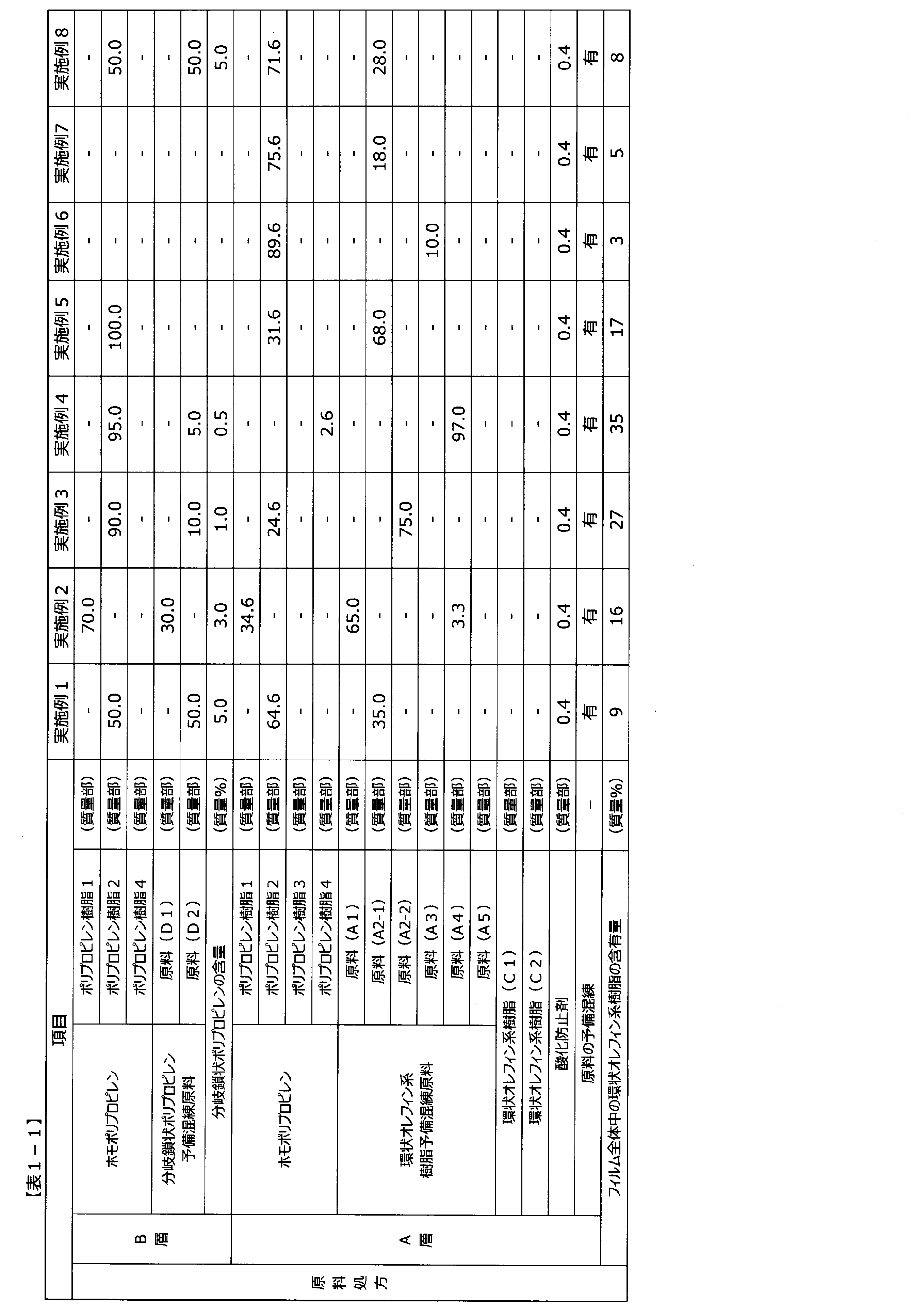
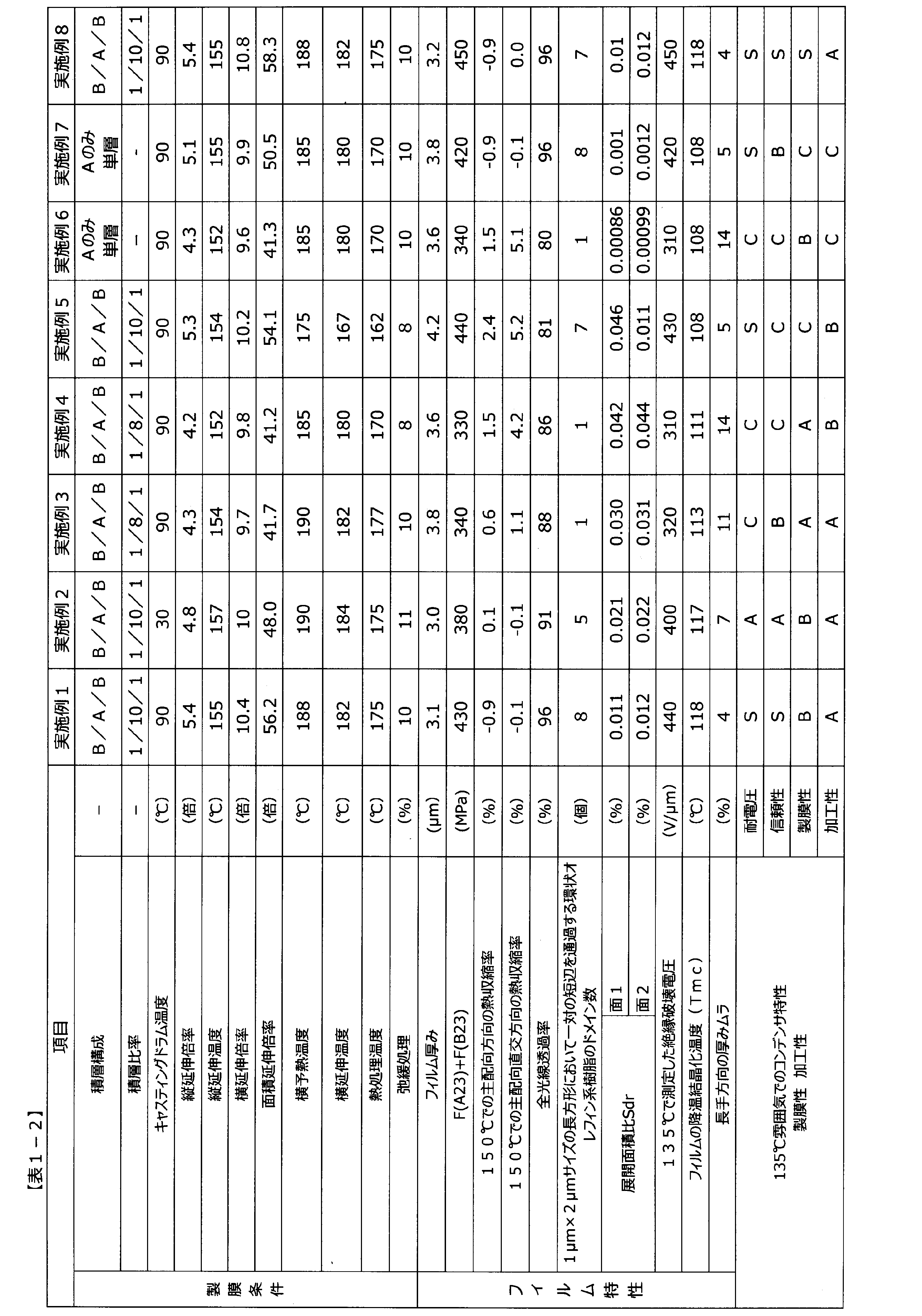


2 海部分
3 島部分(ドメイン)
4 断面X内に一対の短辺が厚み方向に平行となるように定めた1μm×2μmサイズの長方形
5 厚み方向と平行な一対の短辺
Claims (18)
- 23℃で測定した主配向方向の強度をF(A23)、23℃で測定した主配向直交方向の強度をF(B23)としたときに、F(A23)+F(B23)が120MPa以上1000MPa以下であり、150℃で測定した主配向方向の収縮率が-2.0%以上3.0%以下であり、かつ環状オレフィン系樹脂を含む、ポリプロピレンフィルム。
- 少なくとも一方の表面の展開面積比Sdrが0.002%以上0.050%以下である、請求項1に記載のポリプロピレンフィルム。
- 前記環状オレフィン系樹脂とポリプロピレン樹脂とを含む層(A層)を少なくとも1層有し、
主配向方向及び厚み方向に平行な面で前記A層を切断したときの断面を断面Xとしたときに、前記断面X内に一対の短辺が厚み方向に平行となるように定めた1μm×2μmサイズの長方形において、前記一対の短辺を通過する前記環状オレフィン系樹脂のドメインが2個以上存在する、請求項1または2に記載のポリプロピレンフィルム。 - 135℃で測定した絶縁破壊電圧が325V/μmを超え900V/μm以下である、請求項1~3のいずれかに記載のポリプロピレンフィルム。
- 厚みが0.50μm以上5.5μm以下である、請求項1~4のいずれかに記載のポリプロピレンフィルム。
- 150℃で測定したフィルムの主配向直交方向の収縮率が-2.0%以上4.0%以下である、請求項1~5のいずれかに記載のポリプロピレンフィルム。
- ガラス転移温度が125℃以上175℃以下の環状オレフィン系樹脂を含む、請求項1~6のいずれかに記載のポリプロピレンフィルム。
- 全光線透過率が85%以上99.9%以下である、請求項1~7のいずれかに記載のポリプロピレンフィルム。
- 示差走査熱量測定によって測定される降温結晶化温度(Tmc)が110℃以上である、請求項1~8のいずれかに記載のポリプロピレンフィルム。
- 長手方向の厚み斑が0.001%以上15%以下である、請求項1~9のいずれかに記載のポリプロピレンフィルム。
- 請求項1~10のいずれかに記載のポリプロピレンフィルムの少なくとも片面に金属膜を有する、金属膜積層フィルム。
- 請求項11に記載の金属膜積層フィルムを用いてなる、フィルムコンデンサ。
- 容量密度が1.1μF/cm3以上18μF/cm3以下である、請求項12に記載のフィルムコンデンサ。
- 135℃での耐電圧が0.60kV以上である、請求項12または13に記載のフィルムコンデンサ。
- 請求項12~14のいずれかに記載のフィルムコンデンサを有する、パワーコントロールユニット。
- 請求項15に記載のパワーコントロールユニットを有する、電動自動車。
- 請求項15に記載のパワーコントロールユニットを有する、電動航空機。
- 請求項1~10のいずれかに記載のポリプロピレンフィルムを用いてなる、包装材料。
Priority Applications (3)
| Application Number | Priority Date | Filing Date | Title |
|---|---|---|---|
| JP2022578977A JP7424517B1 (ja) | 2022-03-30 | 2022-12-19 | ポリプロピレンフィルム、それを用いた金属膜積層フィルムおよびフィルムコンデンサ |
| EP22935726.4A EP4502018A4 (en) | 2022-03-30 | 2022-12-19 | POLYPROPYLENE FILM, METALLIC MEMBRANE LAMINATED FILM USING IT, AND FILM CAPACITOR |
| CN202280092874.7A CN118786167A (zh) | 2022-03-30 | 2022-12-19 | 聚丙烯膜、使用了该聚丙烯膜的金属膜叠层膜及膜电容器 |
Applications Claiming Priority (2)
| Application Number | Priority Date | Filing Date | Title |
|---|---|---|---|
| JP2022-055758 | 2022-03-30 | ||
| JP2022055758 | 2022-03-30 |
Publications (1)
| Publication Number | Publication Date |
|---|---|
| WO2023188598A1 true WO2023188598A1 (ja) | 2023-10-05 |
Family
ID=88200037
Family Applications (1)
| Application Number | Title | Priority Date | Filing Date |
|---|---|---|---|
| PCT/JP2022/046637 Ceased WO2023188598A1 (ja) | 2022-03-30 | 2022-12-19 | ポリプロピレンフィルム、それを用いた金属膜積層フィルムおよびフィルムコンデンサ |
Country Status (4)
| Country | Link |
|---|---|
| EP (1) | EP4502018A4 (ja) |
| JP (1) | JP7424517B1 (ja) |
| CN (1) | CN118786167A (ja) |
| WO (1) | WO2023188598A1 (ja) |
Cited By (1)
| Publication number | Priority date | Publication date | Assignee | Title |
|---|---|---|---|---|
| WO2024135552A1 (ja) * | 2022-12-19 | 2024-06-27 | 東レ株式会社 | ポリプロピレンフィルム |
Citations (12)
| Publication number | Priority date | Publication date | Assignee | Title |
|---|---|---|---|---|
| JP2015012076A (ja) | 2013-06-27 | 2015-01-19 | 京セラ株式会社 | フィルムコンデンサ |
| WO2016175331A1 (ja) * | 2015-04-30 | 2016-11-03 | 王子ホールディングス株式会社 | コンデンサ用フィルムおよびその製造方法 |
| WO2017022706A1 (ja) | 2015-08-03 | 2017-02-09 | 東レ株式会社 | オレフィン系積層フィルムおよびフィルムコンデンサ |
| JP2018034510A (ja) | 2016-08-30 | 2018-03-08 | 東レ株式会社 | オレフィン系積層フィルムおよびフィルムコンデンサ |
| JP2020520127A (ja) * | 2017-05-15 | 2020-07-02 | ティーディーケイ・エレクトロニクス・アクチェンゲゼルシャフトTdk Electronics Ag | フィルムコンデンサ |
| JP2020521867A (ja) | 2017-04-27 | 2020-07-27 | トパス・アドバンスド・ポリマーズ・ゲゼルシャフト・ミト・ベシュレンクテル・ハフツング | ポリオレフィンフィルムおよびその使用 |
| WO2021070672A1 (ja) * | 2019-10-10 | 2021-04-15 | 東レ株式会社 | ポリオレフィンフィルム |
| WO2021176930A1 (ja) * | 2020-03-06 | 2021-09-10 | 株式会社プライムポリマー | コンデンサ用多層ポリプロピレンフィルム |
| JP6992929B1 (ja) * | 2020-02-21 | 2022-01-13 | 東レ株式会社 | ポリプロピレンフィルム、それを用いた金属膜積層フィルムおよびフィルムコンデンサ |
| JP2022035487A (ja) * | 2020-08-21 | 2022-03-04 | 東レ株式会社 | ポリプロピレンフィルム、積層体、包装材、及び梱包体 |
| JP7188651B1 (ja) * | 2021-03-31 | 2022-12-13 | 東レ株式会社 | ポリプロピレンフィルム、積層体、包装材、及び梱包体 |
| WO2022270577A1 (ja) * | 2021-06-25 | 2022-12-29 | 東レ株式会社 | ポリオレフィン系フィルム、それを用いた金属膜積層フィルム、フィルムコンデンサ、パワーコントロールユニット、電動自動車、および電動航空機 |
Family Cites Families (1)
| Publication number | Priority date | Publication date | Assignee | Title |
|---|---|---|---|---|
| DE102020006588A1 (de) * | 2020-10-27 | 2022-04-28 | Topas Advanced Polymers Gmbh | Kondensator enthaltend biaxial verstreckte Polypropylen-Cycloolefinpolymer-Folie als Dielektrikum und Verwendung dieser Folie |
-
2022
- 2022-12-19 EP EP22935726.4A patent/EP4502018A4/en active Pending
- 2022-12-19 WO PCT/JP2022/046637 patent/WO2023188598A1/ja not_active Ceased
- 2022-12-19 CN CN202280092874.7A patent/CN118786167A/zh active Pending
- 2022-12-19 JP JP2022578977A patent/JP7424517B1/ja active Active
Patent Citations (12)
| Publication number | Priority date | Publication date | Assignee | Title |
|---|---|---|---|---|
| JP2015012076A (ja) | 2013-06-27 | 2015-01-19 | 京セラ株式会社 | フィルムコンデンサ |
| WO2016175331A1 (ja) * | 2015-04-30 | 2016-11-03 | 王子ホールディングス株式会社 | コンデンサ用フィルムおよびその製造方法 |
| WO2017022706A1 (ja) | 2015-08-03 | 2017-02-09 | 東レ株式会社 | オレフィン系積層フィルムおよびフィルムコンデンサ |
| JP2018034510A (ja) | 2016-08-30 | 2018-03-08 | 東レ株式会社 | オレフィン系積層フィルムおよびフィルムコンデンサ |
| JP2020521867A (ja) | 2017-04-27 | 2020-07-27 | トパス・アドバンスド・ポリマーズ・ゲゼルシャフト・ミト・ベシュレンクテル・ハフツング | ポリオレフィンフィルムおよびその使用 |
| JP2020520127A (ja) * | 2017-05-15 | 2020-07-02 | ティーディーケイ・エレクトロニクス・アクチェンゲゼルシャフトTdk Electronics Ag | フィルムコンデンサ |
| WO2021070672A1 (ja) * | 2019-10-10 | 2021-04-15 | 東レ株式会社 | ポリオレフィンフィルム |
| JP6992929B1 (ja) * | 2020-02-21 | 2022-01-13 | 東レ株式会社 | ポリプロピレンフィルム、それを用いた金属膜積層フィルムおよびフィルムコンデンサ |
| WO2021176930A1 (ja) * | 2020-03-06 | 2021-09-10 | 株式会社プライムポリマー | コンデンサ用多層ポリプロピレンフィルム |
| JP2022035487A (ja) * | 2020-08-21 | 2022-03-04 | 東レ株式会社 | ポリプロピレンフィルム、積層体、包装材、及び梱包体 |
| JP7188651B1 (ja) * | 2021-03-31 | 2022-12-13 | 東レ株式会社 | ポリプロピレンフィルム、積層体、包装材、及び梱包体 |
| WO2022270577A1 (ja) * | 2021-06-25 | 2022-12-29 | 東レ株式会社 | ポリオレフィン系フィルム、それを用いた金属膜積層フィルム、フィルムコンデンサ、パワーコントロールユニット、電動自動車、および電動航空機 |
Non-Patent Citations (2)
| Title |
|---|
| MOTONOBU KAWAINIKKEI BP: "Film Capacitor Breakthrough, from Car to Energy", NIKKEI ELECTRONICS, 17 September 2012 (2012-09-17), pages 57 - 62 |
| See also references of EP4502018A4 |
Cited By (1)
| Publication number | Priority date | Publication date | Assignee | Title |
|---|---|---|---|---|
| WO2024135552A1 (ja) * | 2022-12-19 | 2024-06-27 | 東レ株式会社 | ポリプロピレンフィルム |
Also Published As
| Publication number | Publication date |
|---|---|
| EP4502018A4 (en) | 2026-04-01 |
| JP7424517B1 (ja) | 2024-01-30 |
| EP4502018A1 (en) | 2025-02-05 |
| JPWO2023188598A1 (ja) | 2023-10-05 |
| CN118786167A (zh) | 2024-10-15 |
Similar Documents
| Publication | Publication Date | Title |
|---|---|---|
| CN111051400B (zh) | 聚丙烯膜、金属膜叠层膜及膜电容器 | |
| JP6160782B2 (ja) | オレフィン系積層フィルムおよびフィルムコンデンサ | |
| JP7135320B2 (ja) | 二軸配向ポリプロピレンフィルム、金属膜積層フィルムおよびフィルムコンデンサ | |
| JP4962082B2 (ja) | 金属化二軸配向ポリプロピレンフィルム及びこれからなるコンデンサ | |
| US20240279410A1 (en) | Polyolefin-based film, metallized film including same, film capacitor, power control unit, electric vehicle, and electric aircraft | |
| KR20180005670A (ko) | 폴리프로필렌 필름, 금속막 적층 필름 및 필름 콘덴서 그리고 이들의 제조 방법 | |
| JP6926827B2 (ja) | オレフィン系積層フィルムおよびフィルムコンデンサ | |
| US12020871B2 (en) | Polypropylene film, metal layer laminated film using same, and film capacitor | |
| JP7188651B1 (ja) | ポリプロピレンフィルム、積層体、包装材、及び梱包体 | |
| JP7424517B1 (ja) | ポリプロピレンフィルム、それを用いた金属膜積層フィルムおよびフィルムコンデンサ | |
| JP7318187B2 (ja) | ポリプロピレンフィルム、金属膜積層フィルムおよびフィルムコンデンサ | |
| CN119654369A (zh) | 双轴取向聚烯烃膜 | |
| WO2024135552A1 (ja) | ポリプロピレンフィルム | |
| JP7347699B1 (ja) | ポリオレフィン系フィルム、積層体、包装材、及び梱包体 | |
| CN117480202A (zh) | 聚烯烃系膜、使用其的金属膜叠层膜、膜电容器、动力控制单元、电动车及电动航空器 | |
| WO2023188599A1 (ja) | ポリオレフィン系フィルム、積層体、包装材、及び梱包体 | |
| JP2025146739A (ja) | ポリプロピレンフィルム |
Legal Events
| Date | Code | Title | Description |
|---|---|---|---|
| WWE | Wipo information: entry into national phase |
Ref document number: 2022578977 Country of ref document: JP |
|
| 121 | Ep: the epo has been informed by wipo that ep was designated in this application |
Ref document number: 22935726 Country of ref document: EP Kind code of ref document: A1 |
|
| WWE | Wipo information: entry into national phase |
Ref document number: 202280092874.7 Country of ref document: CN |
|
| WWE | Wipo information: entry into national phase |
Ref document number: 2022935726 Country of ref document: EP |
|
| NENP | Non-entry into the national phase |
Ref country code: DE |
|
| ENP | Entry into the national phase |
Ref document number: 2022935726 Country of ref document: EP Effective date: 20241030 |