WO2023189807A1 - 物体検出装置 - Google Patents
物体検出装置 Download PDFInfo
- Publication number
- WO2023189807A1 WO2023189807A1 PCT/JP2023/010838 JP2023010838W WO2023189807A1 WO 2023189807 A1 WO2023189807 A1 WO 2023189807A1 JP 2023010838 W JP2023010838 W JP 2023010838W WO 2023189807 A1 WO2023189807 A1 WO 2023189807A1
- Authority
- WO
- WIPO (PCT)
- Prior art keywords
- frequency
- wave
- reflected wave
- information
- unit
- Prior art date
- Legal status (The legal status is an assumption and is not a legal conclusion. Google has not performed a legal analysis and makes no representation as to the accuracy of the status listed.)
- Ceased
Links
Images





Classifications
-
- G—PHYSICS
- G01—MEASURING; TESTING
- G01S—RADIO DIRECTION-FINDING; RADIO NAVIGATION; DETERMINING DISTANCE OR VELOCITY BY USE OF RADIO WAVES; LOCATING OR PRESENCE-DETECTING BY USE OF THE REFLECTION OR RERADIATION OF RADIO WAVES; ANALOGOUS ARRANGEMENTS USING OTHER WAVES
- G01S15/00—Systems using the reflection or reradiation of acoustic waves, e.g. sonar systems
- G01S15/88—Sonar systems specially adapted for specific applications
- G01S15/93—Sonar systems specially adapted for specific applications for anti-collision purposes
- G01S15/931—Sonar systems specially adapted for specific applications for anti-collision purposes of land vehicles
-
- G—PHYSICS
- G01—MEASURING; TESTING
- G01S—RADIO DIRECTION-FINDING; RADIO NAVIGATION; DETERMINING DISTANCE OR VELOCITY BY USE OF RADIO WAVES; LOCATING OR PRESENCE-DETECTING BY USE OF THE REFLECTION OR RERADIATION OF RADIO WAVES; ANALOGOUS ARRANGEMENTS USING OTHER WAVES
- G01S15/00—Systems using the reflection or reradiation of acoustic waves, e.g. sonar systems
- G01S15/02—Systems using the reflection or reradiation of acoustic waves, e.g. sonar systems using reflection of acoustic waves
- G01S15/50—Systems of measurement, based on relative movement of the target
-
- G—PHYSICS
- G01—MEASURING; TESTING
- G01S—RADIO DIRECTION-FINDING; RADIO NAVIGATION; DETERMINING DISTANCE OR VELOCITY BY USE OF RADIO WAVES; LOCATING OR PRESENCE-DETECTING BY USE OF THE REFLECTION OR RERADIATION OF RADIO WAVES; ANALOGOUS ARRANGEMENTS USING OTHER WAVES
- G01S7/00—Details of systems according to groups G01S13/00, G01S15/00, G01S17/00
- G01S7/52—Details of systems according to groups G01S13/00, G01S15/00, G01S17/00 of systems according to group G01S15/00
- G01S7/523—Details of pulse systems
- G01S7/524—Transmitters
-
- G—PHYSICS
- G01—MEASURING; TESTING
- G01S—RADIO DIRECTION-FINDING; RADIO NAVIGATION; DETERMINING DISTANCE OR VELOCITY BY USE OF RADIO WAVES; LOCATING OR PRESENCE-DETECTING BY USE OF THE REFLECTION OR RERADIATION OF RADIO WAVES; ANALOGOUS ARRANGEMENTS USING OTHER WAVES
- G01S7/00—Details of systems according to groups G01S13/00, G01S15/00, G01S17/00
- G01S7/52—Details of systems according to groups G01S13/00, G01S15/00, G01S17/00 of systems according to group G01S15/00
- G01S7/523—Details of pulse systems
- G01S7/526—Receivers
- G01S7/527—Extracting wanted echo signals
Definitions
- Embodiments of the present invention relate to an object detection device.
- object detection devices In systems that support the travel of moving objects such as vehicles, object detection devices are used that detect obstacles around moving objects by transmitting and receiving ultrasonic waves.
- multipath may occur in which reflected waves from the same obstacle are received by the receiving unit through different routes, depending on the shape of the obstacle and the surrounding environment.
- the accuracy of detecting obstacles may decrease due to phenomena such as a decrease in amplitude value due to antiphase waves.
- one of the problems that the embodiments of the present invention aim to solve is to provide an object detection device that can reduce the influence of multipath and improve the accuracy of detecting obstacles.
- An object detection device includes a transmitter that transmits a transmit wave in which a plurality of ultrasonic waves having different frequencies are multiplexed, and a transmitter that receives a reflected wave generated when the transmit wave is reflected by an object. frequency analysis that generates reflected wave frequency information indicating a plurality of frequency components included in the reflected wave, and separated echo information indicating changes over time in amplitude values for each of the plurality of frequency components included in the reflected wave.
- the apparatus includes a Doppler detection section that calculates a Doppler frequency based on frequency interval information indicating an interval between a plurality of frequency components included in the frequency component, and a correction section that corrects distance information based on the Doppler frequency.
- distance information can be generated using a plurality of frequency components, and the distance information can be corrected based on the Doppler frequency calculated with high accuracy using frequency interval information.
- the influence of multipath can be reduced and the accuracy of detecting obstacles can be improved.
- the Doppler detection unit interpolates deficiencies in multiple frequency components included in the reflected wave based on the frequency interval information, and calculates the Doppler frequency based on the difference between the frequency component of the reflected wave after interpolation and the frequency component of the transmitted wave. may be calculated.
- Doppler frequency can be calculated with high precision.
- the distance information generation unit may generate distance information based on the largest maximum amplitude value among a plurality of amplitude values detected for each frequency component at the same time, which is acquired from the separated echo information.
- the distance information generation unit may generate the distance information based on corrected echo information indicating a change in the maximum amplitude value over time.
- transmission of the transmitted wave and reception of the reflected wave may be performed using a common vibrator.
- FIG. 1 is a top view showing an example of the configuration of a vehicle according to an embodiment.
- FIG. 2 is a block diagram showing an example of the hardware configuration of the vehicle control system according to the embodiment.
- FIG. 3 is a perspective view showing an example of the configuration of the vibrator according to the embodiment.
- FIG. 4 is a diagram illustrating an example of a distance calculation method using the TOF method.
- FIG. 5 is a block diagram showing an example of the functional configuration of the object detection device according to the embodiment.
- FIG. 6 is a diagram illustrating an example of separated echo information according to the embodiment.
- FIG. 7 is a diagram illustrating an example of corrected echo information according to the embodiment.
- FIG. 8 is a diagram illustrating an example of FFT analysis results for reflected waves according to the embodiment.
- FIG. 9 is a flowchart illustrating an example of processing in the object detection device according to the embodiment.
- FIG. 10 is a perspective view showing an example of the configuration of a vibrator according to a modification.
- FIG. 1 is a top view showing an example of the configuration of a vehicle 1 according to an embodiment.
- the vehicle 1 is an example of a moving body on which the object detection device of this embodiment is mounted.
- the object detection device of this embodiment transmits a transmission wave (ultrasonic wave) from the vehicle 1 and receives a reflected wave generated when the transmission wave is reflected by an object.
- This is a device that detects obstacles around the vehicle 1 based on information such as Doppler shift.
- the object detection device of this embodiment includes a plurality of transmitting/receiving units 21A to 21L (hereinafter abbreviated as transmitting/receiving unit 21 when there is no need to distinguish between the plurality of transmitting/receiving units 21A to 21L).
- Each transmitting/receiving unit 21 is installed in the vehicle body 2 as the exterior of the vehicle 1, transmits a transmission wave toward the outside of the vehicle body 2, and receives reflected waves from objects existing outside the vehicle body 2.
- transmitting/receiving units 21A to 21D are arranged at the front end of the vehicle body 2
- four transmitting/receiving units 21E to 21H are arranged at the rear end
- two transmitting/receiving units 21I, 21J are arranged at the right side.
- two transmitter/receivers 21K and 21L are arranged on the left side. Note that the number and installation positions of the transmitting/receiving sections 21 are not limited to this example.
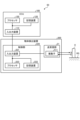
- FIG. 2 is a block diagram showing an example of the hardware configuration of the vehicle control system 50 according to the embodiment.
- Vehicle control system 50 performs processing for controlling vehicle 1 based on information output from object detection device 200.
- Vehicle control system 50 of this embodiment includes ECU 100 and object detection device 200.
- the object detection device 200 includes a plurality of transmitting/receiving sections 21 and a control section 220.
- Each transmitting/receiving section 21 includes a vibrator 511 configured using a piezoelectric element, an amplifier, etc., and realizes transmitting and receiving of ultrasonic waves by the vibration of the vibrator 511.
- each transmitter/receiver 21 transmits ultrasonic waves generated according to the vibration of the vibrator 511 as a transmission wave Wt, and the transmission wave Wt is reflected by objects such as an obstacle O and a road surface RS.
- the vibration of the vibrator 511 caused by the reflected wave Wr generated by the vibration is detected.
- the vibration of the vibrator 511 is converted into an electrical signal, and based on the electrical signal, TOF corresponding to the distance from the transmitter/receiver 21 to the obstacle O, Doppler shift information corresponding to the relative speed of the obstacle O, etc. can be obtained. .
- FIG. 2 illustrates a configuration in which both transmission of the transmitted wave Wt and reception of the reflected wave Wr are performed using a common vibrator 511
- the configuration of the transmitting/receiving section 21 is limited to this. It is not something that will be done.
- a vibrator for transmitting the transmitted wave Wt and a vibrator for receiving the reflected wave Wr may be provided separately.
- the control unit 220 includes an input/output device 221, a storage device 222, and a processor 223.
- the input/output device 221 is an interface device that enables information to be transmitted and received between the control section 220 and the outside (transmission/reception section 21, ECU 100, etc.).
- the storage device 222 includes a main storage device such as ROM (Read Only Memory) and RAM (Random Access Memory), and auxiliary storage devices such as HDD (Hard Disk Drive) and SSD (Solid State Drive).
- the processor 223 is an integrated circuit that executes various processes to realize the functions of the control unit 220, such as a CPU (Central Processing Unit) that operates according to a program, or an ASIC (Application Specific Integrated Circuit) designed for a specific purpose. It can be configured using etc.
- the processor 223 reads and executes programs stored in the storage device 222 to perform various calculation processes and control processes.
- the ECU 100 is a unit that executes various processes for controlling the vehicle 1 based on various information obtained from the object detection device 200 and the like.
- ECU 100 includes an input/output device 110, a storage device 120, and a processor 130.
- the input/output device 110 is an interface device that enables information to be sent and received between the ECU 100 and external mechanisms (object detection device 200, drive mechanism, braking mechanism, steering mechanism, transmission mechanism, in-vehicle display, speaker, various sensors, etc.). It is.
- the storage device 120 includes a main storage device such as ROM and RAM, and an auxiliary storage device such as HDD and SSD.
- the processor 130 is an integrated circuit that executes various processes to realize the functions of the ECU 100, and may be configured using, for example, a CPU, an ASIC, or the like.
- the processor 130 reads programs stored in the storage device 120 and executes various calculation processes and control processes.
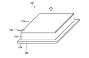
- FIG. 3 is a perspective view showing an example of the configuration of the vibrator 511 according to the embodiment.
- the vibrator 511 includes an upper electrode 521, an upper wiring 522, a piezoelectric body 523, a lower electrode 524, and a lower wiring 525.
- the upper electrode 521 is provided on the upper surface of the piezoelectric body 523 and is used as an electrode for voltage application.
- the upper wiring 522 is connected to the upper electrode 521 and a predetermined AC power source.
- the lower electrode 524 is provided on the lower surface of the piezoelectric body 523 and is used as a ground electrode.
- the lower wiring 525 is connected to the lower electrode 524 and a predetermined ground electrode.
- the above configuration is an example, and the configuration of the vibrator 511 is not limited to this.
- the upper electrode 521 may be used as a ground electrode
- the lower electrode 524 may be used as an electrode for voltage application.
- FIG. 4 is a diagram showing an example of a distance calculation method using the TOF method.
- FIG. 4 exemplifies an envelope L11 indicating a change over time in the amplitude value (signal intensity) of the ultrasound transmitted and received by the transmitting/receiving unit 210.
- the horizontal axis corresponds to time (TOF)
- the vertical axis corresponds to the amplitude value of the ultrasound transmitted and received by the transmitting/receiving section 210 (the magnitude of the vibration of the transducer 511).
- the envelope L11 indicates a change over time in the amplitude value indicating the magnitude of the vibration of the vibrator 511. From the envelope L11 illustrated in FIG. 4, the vibrator 511 is driven and vibrates for a time Ta from the timing t0, and the transmission of the transmission wave is completed at the timing t1, and then the time Tb until the timing t2 is reached. It can be seen that during this period, the vibration of the vibrator 511 due to inertia continues while being attenuated. Therefore, in the graph shown in FIG. 4, the time Tb corresponds to the so-called reverberation time.
- the envelope L11 reaches a peak at timing t4, when time Tp has elapsed from timing t0 when transmission of the transmission wave started, at which the magnitude of the vibration of the vibrator 511 exceeds the detection threshold Ith.
- This detection threshold Ith determines whether the vibration of the vibrator 511 is caused by reception of a reflected wave from an obstacle O (another vehicle, a structure, a pedestrian, etc.) or an object other than the obstacle O (for example, a road surface RS). This value is set to identify whether the wave was caused by the reception of a reflected wave from a source such as Note that although the detection threshold Ith is shown here as a constant value, the detection threshold Ith may be a variable value that changes depending on the situation. Vibrations having a peak equal to or higher than the detection threshold Ith can be considered to be caused by the reception of reflected waves from the obstacle O.
- the envelope L11 of this example shows that the vibration of the vibrator 511 is attenuated after timing t4. Therefore, the timing t4 corresponds to the timing at which the reception of the reflected wave from the obstacle O is completed, in other words, the timing at which the transmission wave last transmitted at the timing t1 returns as a reflected wave.
- timing t3 which is the starting point of the peak at timing t4 is the timing when the reception of the reflected wave from the obstacle O starts, in other words, the transmitted wave first transmitted at timing t0 is the reflected wave. It corresponds to the timing of the return. Therefore, the time ⁇ T between the timing t3 and the timing t4 is equal to the time Ta as the transmission time of the transmission wave.
- the timing t0 when the transmission wave starts to be transmitted can be easily identified as the timing when the object detection device 200 starts operating, and the time Ta as the transmission time of the transmission wave is predetermined by setting or the like. Therefore, by specifying the timing t4 at which the intensity of the reflected wave reaches its peak at or above the detection threshold Ith, the distance from the transmission/reception source to the obstacle O can be determined.
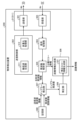
- FIG. 5 is a block diagram showing an example of the functional configuration of the object detection device 200 according to the embodiment.
- the object detection device 200 of this embodiment includes a transmitting section 301, a transmission controlling section 302, a receiving section 303, a signal processing section 304, a frequency analyzing section 305, a distance information generating section 306, a Doppler detecting section 307, a storage section 308, and a correcting section. It has 309.
- These functional components 301 to 309 can be realized, for example, by cooperation between hardware components as shown in FIG. 2 and software components such as programs and firmware. Furthermore, at least a portion of these functional components 301 to 309 may be realized by dedicated hardware (circuits, etc.).
- the transmitter 301 transmits a transmission wave Wt in which a plurality of ultrasound waves having different frequencies are multiplexed. That is, the transmitted wave Wt is an ultrasonic wave containing multiple frequency components.
- the transmitted wave Wt may be, for example, an ultrasonic wave in which sinusoidal waves having different frequencies in a frequency range of 20 kHz or more are multiplexed.
- the transmitter 301 is configured using the above-described vibrator 511 and the like.
- the transmission control unit 302 performs processing for causing the transmission unit 301 to transmit the transmission wave Wt including a plurality of frequency components as described above.
- the transmission control section 302 of this embodiment includes a carrier generation section 311 and a multiplexing processing section 312.
- the carrier wave generation unit 311 generates a plurality of carrier waves that become the source of the transmission wave Wt.
- the carrier wave generation unit 311 generates, for example, a plurality of sine waves having different frequencies.
- the multiplexing processing unit 312 generates an audio signal by multiplexing a plurality of carrier waves (sine waves) with different frequencies.
- the multiplexing method is not particularly limited, for example, methods such as OFDM (Orthogonal Frequency Division Multiplexing) and FDM (Frequency Division Multiplexing) may be used.
- the transmitter 301 outputs a transmission wave Wt including a plurality of frequency components according to the audio signal generated in this way.
- the receiving unit 303 receives a reflected wave Wr generated when the transmitted wave Wt is reflected by an object.
- the reflected wave Wr becomes an ultrasonic wave including a plurality of frequency components, similar to the transmitted wave Wt.
- the receiving unit 303 is configured using a vibrator 511, an AD conversion circuit, etc., and generates an audio signal of the received reflected wave Wr.
- the transmitter 301 and receiver 303 of this embodiment are configured using a common vibrator 511. That is, the transmission of the transmitted wave Wt and the reception of the reflected wave Wr in each transmitting/receiving section 21 (each of the transmitting/receiving sections 21A to 21L) are performed using a common vibrator 511. As a result, the paths of the transmitted wave Wt and the reflected wave Wr are minimized, so the possibility of multipath occurrence can be reduced compared to the case where a plurality of vibrators are used. Further, since it is not necessary to separately provide a vibrator for each frequency component, an increase in cost can be suppressed.
- the signal processing unit 304 performs predetermined signal processing on the audio signal of the reflected wave Wr.
- the signal processing may include filter processing for the purpose of noise removal, correlation processing for determining the degree of similarity between the transmitted wave Wt and the reflected wave Wr, and the like.
- the frequency analysis unit 305 performs frequency analysis processing on the audio signal of the reflected wave Wr after signal processing, and generates reflected wave frequency information indicating a plurality of frequency components included in the reflected wave Wr. Further, the frequency analysis unit 305 generates separated echo information indicating changes over time in amplitude values for each of the plurality of frequency components included in the reflected wave Wr.
- the frequency analysis process may be, for example, FFT (Fast Fourier Transform).
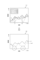
- FIG. 6 is a diagram showing an example of separated echo information 411 according to the embodiment.
- an audio signal 401 of the transmitted wave Wt an audio signal 402 of the reflected wave Wr, and separated echo information 411 are illustrated.
- the transmitted wave Wt includes four types of frequency components A to D
- the reflected wave Wr includes four types of frequency components A' to D'. That is, it is assumed that a Doppler shift occurs between the transmitted wave Wt and the reflected wave Wr due to the movement of the transmitter/receiver 21 or the obstacle O.
- the frequency difference (eg, A'-A) between a frequency component (eg, A) included in the transmitted wave Wt and a frequency component (eg, A') included in the corresponding reflected wave Wr is referred to as a Doppler frequency.
- the reflected wave frequency information in this embodiment is information indicating frequency components A' to D' after Doppler shift.
- the separated echo information 411 is generated based on the result of FFT analysis of the audio signal 402 of the reflected wave Wr.
- the horizontal axis corresponds to the elapsed time since the transmission wave Wt was transmitted, and the vertical axis corresponds to the amplitude value of the reflected wave Wr.
- the separated echo information 411 indicates changes over time in the amplitude values of each of the four types of frequency components A' to D' included in the reflected wave Wr.
- the object detection device 200 of this embodiment includes means for reducing the influence of such multipaths.
- the distance information generation unit 306 generates distance information regarding the distance from the reference position (for example, the installation position of the transmitting/receiving unit 21, etc.) to the object (obstacle O) based on the separated echo information 411.
- the distance information is output to, for example, the ECU 100 (see FIG. 2), and is used for automatic driving control, danger avoidance control, etc. of the vehicle 1.
- the distance information generation section 306 of this embodiment includes a corrected echo information generation section 321.
- the corrected echo information generation unit 321 generates corrected echo information based on the largest maximum amplitude value among a plurality of amplitude values detected for each frequency component at the same time, which is acquired from the separated echo information 411.
- the corrected echo information may be, for example, information indicating a change in the maximum amplitude value over time.
- FIG. 7 is a diagram showing an example of the corrected echo information 421 according to the embodiment.
- the corrected echo information 421 is generated by generating a maximum value line L1 that indicates a change over time in a plurality of maximum amplitude values (amplitude values corresponding to dot positions in FIG. 7) obtained from the separated echo information 411. .
- the maximum amplitude value corresponding to timing t1 is the amplitude value A' (solid line)
- the maximum amplitude value corresponding to timing t2 is the amplitude value C' (dotted chain line).
- a comparison is made between the maximum value line L1 and a reference line Lref (in this example, the line corresponding to frequency component B) indicating the change over time in the amplitude value of a single frequency component. ing.
- a reference line Lref in this example, the line corresponding to frequency component B
- the reference line Lref in a single frequency component, there appears a time period in which the amplitude value drops significantly due to the influence of multipath, but such a time period does not exist in the maximum value line L1.
- the Doppler detection unit 307 calculates the Doppler frequency based on the reflected wave frequency information, the transmitted wave frequency information, and the frequency interval information 308.
- the reflected wave frequency information is information indicating a plurality of frequency components A' to D' included in the reflected wave Wr.
- the transmission wave frequency information is information indicating a plurality of frequency components A to D included in the transmission wave Wt.
- the frequency interval information is information indicating the interval between a plurality of frequency components A to D included in the transmission wave Wt (frequency difference between two adjacent frequency components). The interval may be constant or different over the entire interval between the plurality of frequency components A to D.
- the transmission wave frequency information and frequency interval information may be stored in advance in the storage section 308 or may be acquired from the transmission control section 302.
- the Doppler detection unit 307 interpolates deficiencies in a plurality of frequency components A' to D' included in the reflected wave Wr based on the frequency interval information, and combines the interpolated frequency components A' to D' with the transmitted wave Wt.
- the Doppler frequency is calculated based on the difference between the frequency components A to D.
- the correction unit 309 corrects the distance information generated by the distance information generation unit 306 based on the Doppler frequency detected by the Doppler detection unit 307.
- the Doppler detection unit 307 of this embodiment uses the frequency interval information to interpolate the frequency components missing due to the influence of multipath etc., and calculates the Doppler frequency using the interpolated frequency components.
- FIG. 8 is a diagram showing an example of an FFT analysis result for the reflected wave Wr of the embodiment.
- the graph shown in FIG. 8 is an example of an analysis result corresponding to one time window in FFT analysis of the reflected wave Wr.
- peaks Pa to Pd are detected for four types of frequency components A' to D' included in the reflected wave Wr, respectively.
- ⁇ f indicates the interval (frequency difference) between a plurality of frequency components A to D included in the transmitted wave Wt.
- the interval ⁇ f is a value that can be similarly applied to the intervals between the plurality of frequency components A' to D' of the reflected wave Wr.
- FIG. 8 a state in which the peak Pb of the frequency component B' is much lower than the original peak Pb' is illustrated.
- Such a phenomenon may occur due to the influence of multipath as described above.
- the amplitude value of peak Pb becomes smaller than the threshold value, increasing the possibility that frequency component B' will not be detected.
- the Doppler detection unit 307 of this embodiment uses the interval ⁇ f to complement the missing frequency component B'.
- the missing frequency component B' can be interpolated by adding or subtracting the interval ⁇ f from the frequency components A', C', D' of the other detected peaks Pa, Pc, Pd. Then, by finding the difference between the frequency component of the reflected wave Wr and the frequency component of the transmitted wave Wt interpolated in this way, the Doppler frequency can be calculated with high precision.
- the frequency component A' falls below the original peak Pa.
- the interval ⁇ f is added or subtracted based on the frequency components B', C', and D' of the other detected peaks Pb, Pc, and Pd. By doing so, the frequency component A' of the missing peak Pa can be interpolated.
- the Doppler frequency can be determined with high precision by comparing the predicted amount of Doppler shift A' with the value of the interval ⁇ f from frequency component B' and determining consistency. It is possible to calculate.
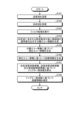
- FIG. 9 is a flowchart illustrating an example of processing in the object detection device 200 according to the embodiment.
- the transmitting unit 301 transmits a transmitted wave Wt (S101), and the receiving unit 303 receives a reflected wave Wr (S102).
- the transmission of the transmitted wave Wt and the reception of the reflected wave Wr are performed by a common vibrator 511 (one transmitting/receiving section 21).
- the signal processing unit 304 performs filter processing on the audio signal 402 of the reflected wave Wr (S103).
- the frequency analysis unit 305 executes a frequency analysis process on the reflected wave Wr after the filtering process, and generates separated echo information 411 indicating a change in amplitude value over time for each frequency component included in the reflected wave Wr (S104).
- the distance information generating unit 306 (corrected echo information generating unit 321) generates corrected echo information 421 indicating a change in maximum amplitude value over time based on the separated echo information 411 (S105). Then, the distance information generation unit 306 generates distance information regarding the distance to the obstacle O based on the corrected echo information 421 (S106).
- the Doppler detection unit 307 calculates the Doppler frequency based on the reflected wave frequency information, the transmitted wave frequency information, and the frequency interval information (S107). At this time, the Doppler detection unit 307 interpolates, for example, frequency components missing due to the influence of multipath etc. among the plurality of frequency components included in the reflected wave Wr using frequency interval information (interval ⁇ f), and The Doppler frequency is calculated based on the difference between the frequency component of Wr and the frequency component of the transmitted wave Wt. Then, the correction unit 309 corrects the frequency distance information based on the Doppler frequency (S108).
- Doppler frequency can be calculated with high accuracy by using frequency interval information indicating the interval between multiple frequency components included in a transmitted wave, and highly accurate distance information can be generated. . Thereby, it is possible to reduce the influence of multipath etc. and improve the accuracy of detecting obstacles.
- FIG. 10 is a perspective view showing an example of the configuration of a vibrator 551 according to a modification.
- the vibrator 551 of this modification includes nine (3 ⁇ 3) upper electrodes 521a to 521i, nine upper wirings 522a to 522i, a piezoelectric body 523, a lower electrode 524, and a lower wiring 525.
- the nine upper electrodes 521a to 521i are provided in different regions on the upper surface of the piezoelectric body 6 and are electrically insulated from each other.
- Nine upper wirings 522a to 522i are connected to upper electrodes 521a to 521i, respectively.
- a program that causes a computer for example, the processor 223, etc. to execute processes for realizing various functions in the embodiments described above is a file in an installable format or an executable format, and is stored on a CD (Compact Disc)-ROM or a flexible disk ( FD), CD-R (Recordable), DVD (Digital Versatile Disk), and other computer-readable recording media can be recorded and provided. Further, the program may be provided or distributed via a network such as the Internet.
- Transducer 521, 521a to 521i... Upper part Electrode, 522, 522a to 522i... Upper wiring, 523... Piezoelectric body, 524... Lower electrode, 525... Lower wiring, L1... Maximum value line, O... Obstacle, RS... Road surface, Wt... Transmitted wave, Wr... Reflected wave , ⁇ f...interval
Landscapes
- Engineering & Computer Science (AREA)
- Radar, Positioning & Navigation (AREA)
- Remote Sensing (AREA)
- Physics & Mathematics (AREA)
- Computer Networks & Wireless Communication (AREA)
- General Physics & Mathematics (AREA)
- Acoustics & Sound (AREA)
- Measurement Of Velocity Or Position Using Acoustic Or Ultrasonic Waves (AREA)
Abstract
Description
図10は、変形例に係る振動子551の構成の一例を示す斜視図である。本変形例の振動子551は、9枚(3×3枚)の上部電極521a~521i、9本の上部配線522a~522i、圧電体523、下部電極524及び下部配線525を有する。9枚の上部電極521a~521iは、圧電体6の上部側の表面の異なる領域に設けられ、互いに電気的に絶縁されている。9本の上部配線522a~522iは、それぞれ上部電極521a~521iに接続されている。
Claims (5)
- 周波数が異なる複数の超音波が多重化された送信波を送信する送信部と、
前記送信波が物体に反射されることにより発生する反射波を受信する受信部と、
前記反射波に含まれる複数の周波数成分を示す反射波周波数情報と、前記反射波に含まれる複数の周波数成分のそれぞれについて振幅値の経時変化を示す分離エコー情報とを生成する周波数解析部と、
前記分離エコー情報に基づいて前記物体までの距離に関する距離情報を生成する距離情報生成部と、
前記反射波周波数情報と、前記送信波に含まれる複数の周波数成分を示す送信波周波数情報と、前記送信波に含まれる複数の周波数成分の間隔を示す周波数間隔情報とに基づいて、ドップラー周波数を算出するドップラー検出部と、
前記ドップラー周波数に基づいて前記距離情報を補正する補正部と、
を備える物体検出装置。 - 前記ドップラー検出部は、前記周波数間隔情報に基づいて前記反射波に含まれる複数の周波数成分の欠損を補間し、補間後の前記反射波の周波数成分と前記送信波の周波数成分との差分に基づいて前記ドップラー周波数を算出する、
請求項1に記載の物体検出装置。 - 前記距離情報生成部は、前記分離エコー情報から取得される、同一の時間において周波数成分毎に検出された複数の振幅値のうち最も大きい最大振幅値に基づいて前記距離情報を生成する、
請求項1に記載の物体検出装置。 - 前記距離情報生成部は、前記最大振幅値の経時変化を示す補正エコー情報に基づいて前記距離情報を生成する、
請求項3に記載の物体検出装置。 - 前記送信波の送信及び前記反射波の受信は、共通の振動子を利用して行われる、
請求項1~4のいずれか1項に記載の物体検出装置。
Priority Applications (4)
| Application Number | Priority Date | Filing Date | Title |
|---|---|---|---|
| CN202380020927.9A CN118679405A (zh) | 2022-03-31 | 2023-03-20 | 物体检测装置 |
| EP23779823.6A EP4502655A4 (en) | 2022-03-31 | 2023-03-20 | OBJECT DETECTION DEVICE |
| JP2024511873A JP7729476B2 (ja) | 2022-03-31 | 2023-03-20 | 物体検出装置 |
| US18/724,262 US20250093503A1 (en) | 2022-03-31 | 2023-03-20 | Object detection device |
Applications Claiming Priority (2)
| Application Number | Priority Date | Filing Date | Title |
|---|---|---|---|
| JP2022059990 | 2022-03-31 | ||
| JP2022-059990 | 2022-03-31 |
Publications (1)
| Publication Number | Publication Date |
|---|---|
| WO2023189807A1 true WO2023189807A1 (ja) | 2023-10-05 |
Family
ID=88201044
Family Applications (1)
| Application Number | Title | Priority Date | Filing Date |
|---|---|---|---|
| PCT/JP2023/010838 Ceased WO2023189807A1 (ja) | 2022-03-31 | 2023-03-20 | 物体検出装置 |
Country Status (5)
| Country | Link |
|---|---|
| US (1) | US20250093503A1 (ja) |
| EP (1) | EP4502655A4 (ja) |
| JP (1) | JP7729476B2 (ja) |
| CN (1) | CN118679405A (ja) |
| WO (1) | WO2023189807A1 (ja) |
Cited By (1)
| Publication number | Priority date | Publication date | Assignee | Title |
|---|---|---|---|---|
| WO2025164629A1 (ja) * | 2024-02-02 | 2025-08-07 | 株式会社アイシン | 物体検出装置 |
Citations (5)
| Publication number | Priority date | Publication date | Assignee | Title |
|---|---|---|---|---|
| JPH01187485A (ja) * | 1988-01-21 | 1989-07-26 | Nec Corp | 超音波距離測定方法 |
| JPH03243881A (ja) * | 1990-02-21 | 1991-10-30 | Japan Radio Co Ltd | 超音波探知装置 |
| JPH0424580A (ja) * | 1990-05-18 | 1992-01-28 | Nec Corp | ソーナー装置 |
| WO2017141370A1 (ja) | 2016-02-17 | 2017-08-24 | 三菱電機株式会社 | 物体検出装置、物体検出方法及び物体検出プログラム |
| JP2020153876A (ja) * | 2019-03-20 | 2020-09-24 | アイシン精機株式会社 | 物体検出装置 |
-
2023
- 2023-03-20 US US18/724,262 patent/US20250093503A1/en active Pending
- 2023-03-20 JP JP2024511873A patent/JP7729476B2/ja active Active
- 2023-03-20 WO PCT/JP2023/010838 patent/WO2023189807A1/ja not_active Ceased
- 2023-03-20 CN CN202380020927.9A patent/CN118679405A/zh active Pending
- 2023-03-20 EP EP23779823.6A patent/EP4502655A4/en active Pending
Patent Citations (5)
| Publication number | Priority date | Publication date | Assignee | Title |
|---|---|---|---|---|
| JPH01187485A (ja) * | 1988-01-21 | 1989-07-26 | Nec Corp | 超音波距離測定方法 |
| JPH03243881A (ja) * | 1990-02-21 | 1991-10-30 | Japan Radio Co Ltd | 超音波探知装置 |
| JPH0424580A (ja) * | 1990-05-18 | 1992-01-28 | Nec Corp | ソーナー装置 |
| WO2017141370A1 (ja) | 2016-02-17 | 2017-08-24 | 三菱電機株式会社 | 物体検出装置、物体検出方法及び物体検出プログラム |
| JP2020153876A (ja) * | 2019-03-20 | 2020-09-24 | アイシン精機株式会社 | 物体検出装置 |
Non-Patent Citations (1)
| Title |
|---|
| See also references of EP4502655A4 |
Cited By (1)
| Publication number | Priority date | Publication date | Assignee | Title |
|---|---|---|---|---|
| WO2025164629A1 (ja) * | 2024-02-02 | 2025-08-07 | 株式会社アイシン | 物体検出装置 |
Also Published As
| Publication number | Publication date |
|---|---|
| EP4502655A1 (en) | 2025-02-05 |
| JPWO2023189807A1 (ja) | 2023-10-05 |
| EP4502655A4 (en) | 2025-07-09 |
| JP7729476B2 (ja) | 2025-08-26 |
| US20250093503A1 (en) | 2025-03-20 |
| CN118679405A (zh) | 2024-09-20 |
Similar Documents
| Publication | Publication Date | Title |
|---|---|---|
| JP7729476B2 (ja) | 物体検出装置 | |
| JP2021196254A (ja) | 物体検出装置 | |
| JP7729243B2 (ja) | 物体検出装置 | |
| JP7230619B2 (ja) | 物体検出装置 | |
| WO2022239470A1 (ja) | 物体検出装置 | |
| WO2023282098A1 (ja) | 物体検出装置及び物体検出方法 | |
| JP2022122197A (ja) | 物体検出装置及び移動体制御装置 | |
| WO2022239480A1 (ja) | 物体検出装置 | |
| US12517246B2 (en) | Object detection device | |
| JP2025119931A (ja) | 物体検出装置 | |
| WO2023282265A1 (ja) | 物体検出装置、物体検出方法、及びプログラム | |
| JP2025120046A (ja) | 物体検出装置 | |
| JP2025062323A (ja) | 物体検出装置 | |
| WO2025164629A1 (ja) | 物体検出装置 | |
| JP2025136665A (ja) | 物体検出装置 | |
| JP7547853B2 (ja) | 物体検出装置 | |
| JP7567221B2 (ja) | 物体検出装置 | |
| WO2023282097A1 (ja) | 物体検出装置 | |
| JP2025121307A (ja) | 物体検出装置 | |
| JP2022122196A (ja) | 物体検出装置及び移動体制御装置 | |
| WO2025074779A1 (ja) | 物体検出装置 | |
| JP2026009666A (ja) | 物体検出装置 | |
| JP2025118145A (ja) | 物体検出装置 |
Legal Events
| Date | Code | Title | Description |
|---|---|---|---|
| 121 | Ep: the epo has been informed by wipo that ep was designated in this application |
Ref document number: 23779823 Country of ref document: EP Kind code of ref document: A1 |
|
| WWE | Wipo information: entry into national phase |
Ref document number: 2024511873 Country of ref document: JP |
|
| WWE | Wipo information: entry into national phase |
Ref document number: 18724262 Country of ref document: US |
|
| WWE | Wipo information: entry into national phase |
Ref document number: 202380020927.9 Country of ref document: CN |
|
| WWE | Wipo information: entry into national phase |
Ref document number: 2023779823 Country of ref document: EP |
|
| ENP | Entry into the national phase |
Ref document number: 2023779823 Country of ref document: EP Effective date: 20241031 |
|
| NENP | Non-entry into the national phase |
Ref country code: DE |
|
| WWP | Wipo information: published in national office |
Ref document number: 18724262 Country of ref document: US |