WO2023190036A1 - ホイール式車両の走行装置 - Google Patents
ホイール式車両の走行装置 Download PDFInfo
- Publication number
- WO2023190036A1 WO2023190036A1 PCT/JP2023/011515 JP2023011515W WO2023190036A1 WO 2023190036 A1 WO2023190036 A1 WO 2023190036A1 JP 2023011515 W JP2023011515 W JP 2023011515W WO 2023190036 A1 WO2023190036 A1 WO 2023190036A1
- Authority
- WO
- WIPO (PCT)
- Prior art keywords
- coupling
- motor shaft
- lubricating oil
- spline
- spline portion
- Prior art date
- Legal status (The legal status is an assumption and is not a legal conclusion. Google has not performed a legal analysis and makes no representation as to the accuracy of the status listed.)
- Ceased
Links
Images


Classifications
-
- F—MECHANICAL ENGINEERING; LIGHTING; HEATING; WEAPONS; BLASTING
- F16—ENGINEERING ELEMENTS AND UNITS; GENERAL MEASURES FOR PRODUCING AND MAINTAINING EFFECTIVE FUNCTIONING OF MACHINES OR INSTALLATIONS; THERMAL INSULATION IN GENERAL
- F16D—COUPLINGS FOR TRANSMITTING ROTATION; CLUTCHES; BRAKES
- F16D1/00—Couplings for rigidly connecting two coaxial shafts or other movable machine elements
- F16D1/10—Quick-acting couplings in which the parts are connected by simply bringing them together axially
-
- B—PERFORMING OPERATIONS; TRANSPORTING
- B60—VEHICLES IN GENERAL
- B60B—VEHICLE WHEELS; CASTORS; AXLES FOR WHEELS OR CASTORS; INCREASING WHEEL ADHESION
- B60B35/00—Axle units; Parts thereof ; Arrangements for lubrication of axles
- B60B35/12—Torque-transmitting axles
- B60B35/14—Torque-transmitting axles composite or split, e.g. half- axles; Couplings between axle parts or sections
-
- B—PERFORMING OPERATIONS; TRANSPORTING
- B60—VEHICLES IN GENERAL
- B60B—VEHICLE WHEELS; CASTORS; AXLES FOR WHEELS OR CASTORS; INCREASING WHEEL ADHESION
- B60B35/00—Axle units; Parts thereof ; Arrangements for lubrication of axles
- B60B35/12—Torque-transmitting axles
- B60B35/16—Axle housings
-
- B—PERFORMING OPERATIONS; TRANSPORTING
- B60—VEHICLES IN GENERAL
- B60K—ARRANGEMENT OR MOUNTING OF PROPULSION UNITS OR OF TRANSMISSIONS IN VEHICLES; ARRANGEMENT OR MOUNTING OF PLURAL DIVERSE PRIME-MOVERS IN VEHICLES; AUXILIARY DRIVES FOR VEHICLES; INSTRUMENTATION OR DASHBOARDS FOR VEHICLES; ARRANGEMENTS IN CONNECTION WITH COOLING, AIR INTAKE, GAS EXHAUST OR FUEL SUPPLY OF PROPULSION UNITS IN VEHICLES
- B60K17/00—Arrangement or mounting of transmissions in vehicles
- B60K17/04—Arrangement or mounting of transmissions in vehicles characterised by arrangement, location or kind of gearing
- B60K17/043—Transmission unit disposed in on near the vehicle wheel, or between the differential gear unit and the wheel
- B60K17/046—Transmission unit disposed in on near the vehicle wheel, or between the differential gear unit and the wheel with planetary gearing having orbital motion
-
- B—PERFORMING OPERATIONS; TRANSPORTING
- B60—VEHICLES IN GENERAL
- B60K—ARRANGEMENT OR MOUNTING OF PROPULSION UNITS OR OF TRANSMISSIONS IN VEHICLES; ARRANGEMENT OR MOUNTING OF PLURAL DIVERSE PRIME-MOVERS IN VEHICLES; AUXILIARY DRIVES FOR VEHICLES; INSTRUMENTATION OR DASHBOARDS FOR VEHICLES; ARRANGEMENTS IN CONNECTION WITH COOLING, AIR INTAKE, GAS EXHAUST OR FUEL SUPPLY OF PROPULSION UNITS IN VEHICLES
- B60K7/00—Disposition of motor in, or adjacent to, traction wheel
- B60K7/0007—Disposition of motor in, or adjacent to, traction wheel the motor being electric
-
- F—MECHANICAL ENGINEERING; LIGHTING; HEATING; WEAPONS; BLASTING
- F16—ENGINEERING ELEMENTS AND UNITS; GENERAL MEASURES FOR PRODUCING AND MAINTAINING EFFECTIVE FUNCTIONING OF MACHINES OR INSTALLATIONS; THERMAL INSULATION IN GENERAL
- F16D—COUPLINGS FOR TRANSMITTING ROTATION; CLUTCHES; BRAKES
- F16D1/00—Couplings for rigidly connecting two coaxial shafts or other movable machine elements
- F16D1/02—Couplings for rigidly connecting two coaxial shafts or other movable machine elements for connecting two abutting shafts or the like
-
- F—MECHANICAL ENGINEERING; LIGHTING; HEATING; WEAPONS; BLASTING
- F16—ENGINEERING ELEMENTS AND UNITS; GENERAL MEASURES FOR PRODUCING AND MAINTAINING EFFECTIVE FUNCTIONING OF MACHINES OR INSTALLATIONS; THERMAL INSULATION IN GENERAL
- F16H—GEARING
- F16H57/00—General details of gearing
- F16H57/04—Features relating to lubrication or cooling or heating
- F16H57/042—Guidance of lubricant
- F16H57/0421—Guidance of lubricant on or within the casing, e.g. shields or baffles for collecting lubricant, tubes, pipes, grooves, channels or the like
- F16H57/0423—Lubricant guiding means mounted or supported on the casing, e.g. shields or baffles for collecting lubricant, tubes or pipes
-
- B—PERFORMING OPERATIONS; TRANSPORTING
- B60—VEHICLES IN GENERAL
- B60K—ARRANGEMENT OR MOUNTING OF PROPULSION UNITS OR OF TRANSMISSIONS IN VEHICLES; ARRANGEMENT OR MOUNTING OF PLURAL DIVERSE PRIME-MOVERS IN VEHICLES; AUXILIARY DRIVES FOR VEHICLES; INSTRUMENTATION OR DASHBOARDS FOR VEHICLES; ARRANGEMENTS IN CONNECTION WITH COOLING, AIR INTAKE, GAS EXHAUST OR FUEL SUPPLY OF PROPULSION UNITS IN VEHICLES
- B60K7/00—Disposition of motor in, or adjacent to, traction wheel
- B60K2007/0038—Disposition of motor in, or adjacent to, traction wheel the motor moving together with the wheel axle
-
- B—PERFORMING OPERATIONS; TRANSPORTING
- B60—VEHICLES IN GENERAL
- B60K—ARRANGEMENT OR MOUNTING OF PROPULSION UNITS OR OF TRANSMISSIONS IN VEHICLES; ARRANGEMENT OR MOUNTING OF PLURAL DIVERSE PRIME-MOVERS IN VEHICLES; AUXILIARY DRIVES FOR VEHICLES; INSTRUMENTATION OR DASHBOARDS FOR VEHICLES; ARRANGEMENTS IN CONNECTION WITH COOLING, AIR INTAKE, GAS EXHAUST OR FUEL SUPPLY OF PROPULSION UNITS IN VEHICLES
- B60K7/00—Disposition of motor in, or adjacent to, traction wheel
- B60K2007/0061—Disposition of motor in, or adjacent to, traction wheel the motor axle being parallel to the wheel axle
-
- B—PERFORMING OPERATIONS; TRANSPORTING
- B60—VEHICLES IN GENERAL
- B60K—ARRANGEMENT OR MOUNTING OF PROPULSION UNITS OR OF TRANSMISSIONS IN VEHICLES; ARRANGEMENT OR MOUNTING OF PLURAL DIVERSE PRIME-MOVERS IN VEHICLES; AUXILIARY DRIVES FOR VEHICLES; INSTRUMENTATION OR DASHBOARDS FOR VEHICLES; ARRANGEMENTS IN CONNECTION WITH COOLING, AIR INTAKE, GAS EXHAUST OR FUEL SUPPLY OF PROPULSION UNITS IN VEHICLES
- B60K7/00—Disposition of motor in, or adjacent to, traction wheel
- B60K2007/0092—Disposition of motor in, or adjacent to, traction wheel the motor axle being coaxial to the wheel axle
-
- B—PERFORMING OPERATIONS; TRANSPORTING
- B60—VEHICLES IN GENERAL
- B60K—ARRANGEMENT OR MOUNTING OF PROPULSION UNITS OR OF TRANSMISSIONS IN VEHICLES; ARRANGEMENT OR MOUNTING OF PLURAL DIVERSE PRIME-MOVERS IN VEHICLES; AUXILIARY DRIVES FOR VEHICLES; INSTRUMENTATION OR DASHBOARDS FOR VEHICLES; ARRANGEMENTS IN CONNECTION WITH COOLING, AIR INTAKE, GAS EXHAUST OR FUEL SUPPLY OF PROPULSION UNITS IN VEHICLES
- B60K6/00—Arrangement or mounting of plural diverse prime-movers for mutual or common propulsion, e.g. hybrid propulsion systems comprising electric motors and internal combustion engines
- B60K6/20—Arrangement or mounting of plural diverse prime-movers for mutual or common propulsion, e.g. hybrid propulsion systems comprising electric motors and internal combustion engines the prime-movers consisting of electric motors and internal combustion engines, e.g. HEVs
- B60K6/22—Arrangement or mounting of plural diverse prime-movers for mutual or common propulsion, e.g. hybrid propulsion systems comprising electric motors and internal combustion engines the prime-movers consisting of electric motors and internal combustion engines, e.g. HEVs characterised by apparatus, components or means specially adapted for HEVs
- B60K6/36—Arrangement or mounting of plural diverse prime-movers for mutual or common propulsion, e.g. hybrid propulsion systems comprising electric motors and internal combustion engines the prime-movers consisting of electric motors and internal combustion engines, e.g. HEVs characterised by apparatus, components or means specially adapted for HEVs characterised by the transmission gearings
-
- B—PERFORMING OPERATIONS; TRANSPORTING
- B60—VEHICLES IN GENERAL
- B60K—ARRANGEMENT OR MOUNTING OF PROPULSION UNITS OR OF TRANSMISSIONS IN VEHICLES; ARRANGEMENT OR MOUNTING OF PLURAL DIVERSE PRIME-MOVERS IN VEHICLES; AUXILIARY DRIVES FOR VEHICLES; INSTRUMENTATION OR DASHBOARDS FOR VEHICLES; ARRANGEMENTS IN CONNECTION WITH COOLING, AIR INTAKE, GAS EXHAUST OR FUEL SUPPLY OF PROPULSION UNITS IN VEHICLES
- B60K6/00—Arrangement or mounting of plural diverse prime-movers for mutual or common propulsion, e.g. hybrid propulsion systems comprising electric motors and internal combustion engines
- B60K6/20—Arrangement or mounting of plural diverse prime-movers for mutual or common propulsion, e.g. hybrid propulsion systems comprising electric motors and internal combustion engines the prime-movers consisting of electric motors and internal combustion engines, e.g. HEVs
- B60K6/42—Arrangement or mounting of plural diverse prime-movers for mutual or common propulsion, e.g. hybrid propulsion systems comprising electric motors and internal combustion engines the prime-movers consisting of electric motors and internal combustion engines, e.g. HEVs characterised by the architecture of the hybrid electric vehicle
- B60K6/46—Series type
-
- B—PERFORMING OPERATIONS; TRANSPORTING
- B60—VEHICLES IN GENERAL
- B60W—CONJOINT CONTROL OF VEHICLE SUB-UNITS OF DIFFERENT TYPE OR DIFFERENT FUNCTION; CONTROL SYSTEMS SPECIALLY ADAPTED FOR HYBRID VEHICLES; ROAD VEHICLE DRIVE CONTROL SYSTEMS FOR PURPOSES NOT RELATED TO THE CONTROL OF A PARTICULAR SUB-UNIT
- B60W2300/00—Indexing codes relating to the type of vehicle
- B60W2300/12—Trucks; Load vehicles
- B60W2300/125—Heavy duty trucks
-
- B—PERFORMING OPERATIONS; TRANSPORTING
- B60—VEHICLES IN GENERAL
- B60Y—INDEXING SCHEME RELATING TO ASPECTS CROSS-CUTTING VEHICLE TECHNOLOGY
- B60Y2200/00—Type of vehicle
- B60Y2200/10—Road Vehicles
- B60Y2200/14—Trucks; Load vehicles, Busses
- B60Y2200/142—Heavy duty trucks
-
- B—PERFORMING OPERATIONS; TRANSPORTING
- B60—VEHICLES IN GENERAL
- B60Y—INDEXING SCHEME RELATING TO ASPECTS CROSS-CUTTING VEHICLE TECHNOLOGY
- B60Y2200/00—Type of vehicle
- B60Y2200/90—Vehicles comprising electric prime movers
- B60Y2200/92—Hybrid vehicles
-
- F—MECHANICAL ENGINEERING; LIGHTING; HEATING; WEAPONS; BLASTING
- F16—ENGINEERING ELEMENTS AND UNITS; GENERAL MEASURES FOR PRODUCING AND MAINTAINING EFFECTIVE FUNCTIONING OF MACHINES OR INSTALLATIONS; THERMAL INSULATION IN GENERAL
- F16D—COUPLINGS FOR TRANSMITTING ROTATION; CLUTCHES; BRAKES
- F16D1/00—Couplings for rigidly connecting two coaxial shafts or other movable machine elements
- F16D1/10—Quick-acting couplings in which the parts are connected by simply bringing them together axially
- F16D2001/103—Quick-acting couplings in which the parts are connected by simply bringing them together axially the torque is transmitted via splined connections
-
- F—MECHANICAL ENGINEERING; LIGHTING; HEATING; WEAPONS; BLASTING
- F16—ENGINEERING ELEMENTS AND UNITS; GENERAL MEASURES FOR PRODUCING AND MAINTAINING EFFECTIVE FUNCTIONING OF MACHINES OR INSTALLATIONS; THERMAL INSULATION IN GENERAL
- F16D—COUPLINGS FOR TRANSMITTING ROTATION; CLUTCHES; BRAKES
- F16D2300/00—Special features for couplings or clutches
- F16D2300/06—Lubrication details not provided for in group F16D13/74
Definitions
- the present disclosure relates to a traveling device suitably used for a wheeled vehicle having wheels, such as a dump truck.
- a traveling device installed in a wheeled vehicle such as a dump truck, includes a cylindrical spindle that is provided on the vehicle body and rotatably supports a rim to which a wheel is attached, an electric motor attached to the spindle, and a cylindrical spindle that rotatably supports a rim to which a wheel is attached.
- a motor shaft that outputs rotation; a rotating shaft extending in the axial direction from the inner peripheral side of the spindle and transmitting the rotation of the motor shaft; and a rotating shaft that decelerates the rotation of the rotating shaft and transmits it to the rim.
- the apparatus includes a deceleration mechanism and a coupling that connects the motor shaft and the rotating shaft.
- a coupling is provided between the rotating shaft and the motor shaft, and a coupling is provided between the rotating shaft and the coupling, and between the motor shaft and the coupling. Spline connected.
- Patent Document 1 discloses a traveling device in which a motor rotation shaft and a reducer input shaft are connected by a spline connection, and a lubricant filled in the spline connection is sealed with a sealing material such as an O-ring. ing.
- the traveling device according to Patent Document 1 the lubricant filled in the spline joint between the motor rotating shaft and the reducer input shaft is sealed using a sealing material, so the lubricant deteriorates and the lubrication performance is reduced. There is a problem that the amount decreases. Furthermore, there is a problem in that it is necessary to periodically replace the lubricant (lubricating operation) in order to prevent wear particles remaining in the spline joint from accelerating wear.
- An object of the present invention is to provide a running device for a wheeled vehicle that can properly lubricate the joint between the motor shaft and the coupling.
- the present invention includes a cylindrical spindle that is provided on the body of a wheeled vehicle and rotatably supports a wheel mounting tube to which a wheel is attached, an electric motor attached to the spindle, and a cylindrical spindle that protrudes from the electric motor and that rotates the electric motor.
- a motor shaft that outputs the rotation of the motor shaft, a rotary shaft extending in the axial direction on the inner peripheral side of the spindle and transmitting the rotation of the motor shaft, and a rotary shaft that decelerates the rotation of the rotary shaft and the wheel mounting tube.
- a running device for a wheeled vehicle comprising: a speed reduction mechanism for transmitting transmission to the speed reduction mechanism; a lubricating oil circulation circuit for supplying lubricating oil to the speed reduction mechanism; and a coupling connecting the motor shaft and the rotating shaft.
- part of the lubricating oil supplied from the lubricating oil circulation circuit to the speed reduction mechanism is diverted to supply joint lubrication to the joint between the motor shaft and the coupling through the inside of the coupling. It is characterized by having a circuit.
- a part of the lubricating oil flowing through the lubricating oil circulation circuit can be supplied to the joint between the motor shaft and the coupling through the joint lubricating circuit, thereby properly lubricating the motor shaft and the coupling. can do.
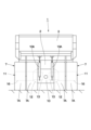
- FIG. 1 is a left side view showing a dump truck to which a traveling device according to an embodiment of the present invention is applied.
- FIG. 3 is a rear view of the dump truck seen from the rear.
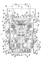
- FIG. 2 is a cross-sectional view of the rear wheel side traveling device viewed from the direction of arrow III-III in FIG. 1.
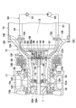
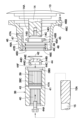
- FIG. 4 is an enlarged view showing a motor shaft, a rotating shaft, a coupling, a coupling housing, etc. in FIG. 3.
- FIG. FIG. 2 is an enlarged view of main parts showing main parts such as a coupling, a lubricating oil passage, a coupling housing, a supply oil passage, and a discharge oil passage.
- FIG. 3 is a sectional view showing the coupling alone.
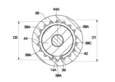
- FIG. 6 is a cross-sectional view of the spline joint between the motor shaft and the coupling, viewed from the direction of arrow VII-VII in FIG. 5.
- FIG. It is an exploded view showing a motor shaft, a rotation shaft, a coupling, a coupling housing, a stopper, etc. in an exploded state.
- a dump truck 1 includes a vehicle body 2 having a sturdy frame structure, a vessel (loading platform) 3 mounted on the vehicle body 2 so as to be able to rise and fall, a cab 5 provided at the front of the vehicle body 2, and wheels.
- the vehicle includes left and right front wheels 6 and left and right rear wheels 7.
- the vessel 3 is formed as a large container for loading heavy objects such as crushed stone, and the rear bottom of the vessel 3 can be raised and lowered (tilted) via a connecting pin 4 or the like on the rear end side of the vehicle body 2. connected.
- An eaves portion 3A that covers the cab 5 from above is integrally provided at the front upper part of the vessel 3.
- the cab 5 is provided at the front of the vehicle body 2, located below the eaves portion 3A.
- the cab 5 forms a driver's cabin, and the interior of the cab 5 is provided with a driver's seat, a steering handle, a plurality of operating levers (none of which are shown), and the like.
- the left and right front wheels 6 are rotatably provided on the front side of the vehicle body 2 (only the left front wheel is shown).
- the left and right front wheels 6 constitute steered wheels steered by the driver.
- the left and right rear wheels 7 are rotatably provided on the rear side of the vehicle body 2.
- the left and right rear wheels 7 constitute driving wheels of the dump truck 1, and are driven to rotate integrally with a wheel mounting tube 17 by a traveling device 11 shown in FIG.
- the rear wheel 7 includes two rows of tires 7A made of dual-wheel tires, and a rim 7B disposed on the radially inner side of the tires 7A.
- the engine 8 is located below the cab 5 and is provided inside the vehicle body 2.
- the engine 8 is configured by, for example, a diesel engine, and rotationally drives an electric motor 13, a hydraulic pump (not shown), etc., which are mounted on the vehicle body 2 and will be described later. Pressure oil discharged from the hydraulic pump is supplied to the hoist cylinder 9, a steering cylinder for power steering (not shown), and the like.
- the hoist cylinder 9 is provided between the vehicle body 2 and the vessel 3.
- the hoist cylinder 9 is located between the front wheels 6 and the rear wheels 7 and is disposed on both the left and right sides of the vehicle body 2, and expands and contracts upward and downward by supplying and discharging pressure oil from a hydraulic pump. , the vessel 3 is undulated (tilted) around the connecting pin 4.
- the axle housing 10 on the rear wheel side is provided on the rear side of the vehicle body 2.
- the axle housing 10 is made of a hollow cylindrical body extending in the left-right direction, and is attached to the rear side of the vehicle body 2 via the left and right rear wheel suspensions 10A. Traveling devices 11 for driving the left and right rear wheels 7 are provided on the left and right sides of the axle housing 10, respectively.
- the traveling devices 11 are provided on both the left and right sides of the axle housing 10, respectively. As shown in FIG. 3, the traveling device 11 includes a spindle 12, an electric motor 13, a rotating shaft 15, a wheel mounting tube 17, a reduction mechanism 21, a coupling 38, a coupling housing 46, and lubricating oil.
- the circuit includes a circulation circuit 50.
- the traveling device 11 decelerates the rotation of the rotary shaft 15 by a deceleration mechanism 21, and rotationally drives the left and right rear wheels 7, which serve as drive wheels, with a large rotational torque.
- the spindle 12 is attached to both left and right sides of the axle housing 10.
- the spindle 12 is formed into a stepped cylindrical shape extending in the axial direction (left-right direction), and has a tapered portion 12A, an intermediate cylindrical portion 12B, and a small diameter cylindrical portion 12C.
- the tapered portion 12A has a tapered shape whose diameter gradually decreases from one axial side of the spindle 12 (the axle housing 10 side) to the other axial side, and is attached to the end of the axle housing 10 using a plurality of bolts 12D. installed.
- the intermediate cylindrical portion 12B is integrally formed on the reduced diameter side of the tapered portion 12A and extends in the axial direction.
- the small diameter cylindrical portion 12C has a smaller outer diameter than the intermediate cylindrical portion 12B, and is integrally formed on the distal end side of the intermediate cylindrical portion 12B.
- a plurality of motor mounting seats 12E protruding radially inward are provided on one axial side of the tapered portion 12A, and an electric motor 13 is mounted on the motor mounting seats 12E.
- An annular flange portion 12F that protrudes radially outward is provided on the outer peripheral side of the tapered portion 12A, and a wet brake 35, which will be described later, is attached to the flange portion 12F.
- the tip of the small-diameter cylindrical portion 12C is an open end, and a cylindrical protrusion 33A of a second-stage carrier 33, which will be described later, is spline-coupled to the inner peripheral side thereof.
- An annular inner protrusion 12G that protrudes radially inward is integrally formed on the inner peripheral side of the axially intermediate portion of the small diameter cylindrical portion 12C, and a bearing 16, which will be described later, is attached to the inner protrusion 12G. There is.
- a radial hole 12H penetrating in the vertical direction (radial direction of the small diameter cylindrical portion 12C) is formed in the lower side of the small diameter cylindrical portion 12C, and a suction pipe 51, which will be described later, is inserted into the radial hole 12H.
- the tip 51A is inserted.
- the electric motor 13 for traveling is arranged within the axle housing 10 and the tapered portion 12A of the spindle 12.
- a plurality of mounting flanges 13A are provided on the outer peripheral side of the electric motor 13, and the mounting flanges 13A are mounted to the motor mounting seat 12E of the spindle 12 (tapered portion 12A) using bolts or the like.
- the motor shaft 14 protrudes from the electric motor 13.
- the electric motor 13 rotates a motor shaft 14 by being supplied with electric power from a generator (not shown) mounted on the vehicle body 2 , and transmits the rotation of the motor shaft 14 to a rotating shaft 15 .
- a motor shaft spline portion 14A having a spline groove is formed on the outer peripheral surface of the motor shaft 14, and the motor shaft spline portion 14A is located on the motor shaft side of a coupling 38, which will be described later. It meshes with the hole spline portion 39.
- a bottomed stopper mounting hole 14C is provided at the protruding end 14B of the motor shaft 14, and a bolt hole (female threaded hole) 14D is formed at the center of the bottom of the stopper mounting hole 14C.
- the rotating shaft 15 is provided extending in the axial direction on the inner peripheral side of the spindle 12.
- the rotating shaft 15 is formed using one long rod-shaped body.
- a rotary shaft spline portion 15A is formed on the outer peripheral surface of one end side of the rotary shaft 15 (on the electric motor 13 side), and the rotary shaft spline portion 15A meshes with a rotary shaft side hole spline portion 40 of a coupling 38, which will be described later. ing.
- the rotating shaft 15 is coupled to the motor shaft 14 of the electric motor 13 via the coupling 38, and is rotationally driven by the electric motor 13.
- the other end of the rotating shaft 15 protrudes from the open end of the small diameter cylindrical portion 12C of the spindle 12, and a sun gear 23, which will be described later, is attached to the other end (projecting end) of the rotating shaft 15.
- An axially intermediate portion of the rotating shaft 15 is rotatably supported by a bearing 16 attached to the inner protrusion 12G of the spindle 12.
- the wheel mounting tube 17 is rotatably provided on the outer peripheral side of the small diameter cylindrical portion 12C that constitutes the spindle 12 via two roller bearings 18.
- the wheel mounting tube 17 is supported by two roller bearings 18, and includes a hollow cylindrical portion 17A extending axially on the outer peripheral side of the small diameter cylindrical portion 12C, and a hollow cylindrical portion 17A extending axially from the tip of the hollow cylindrical portion 17A in a direction away from the spindle 12. It has an extended cylindrical portion 17B extending to .
- a cylindrical rim 7B constituting the rear wheel 7 is removably attached to the outer peripheral side of the wheel mounting tube 17, and the rear wheel 7 rotates together with the wheel mounting tube 17.
- An internal gear 32 and an outer drum 19, which will be described later, are integrally fixed to the end of the extended cylindrical portion 17B of the wheel mounting tube 17 using long bolts 20.
- the outer drum 19 is made of a cylindrical body, and a flange portion 19A provided on one side in the axial direction is fixed to the wheel mounting tube 17 via an internal gear 32.
- the other side of the outer drum 19 in the axial direction is an open end.
- the speed reduction mechanism 21 is provided between the rotating shaft 15 and the wheel mounting tube 17.
- the speed reduction mechanism 21 is constituted by a first-stage planetary gear speed reduction mechanism 22 and a second-stage planetary gear speed reduction mechanism 29, and transmits the rotation of the rotating shaft 15 to the wheel mounting tube 17 by reducing the speed in two steps.
- the first stage planetary gear reduction mechanism 22 includes a sun gear 23, a plurality of planetary gears 24, and a carrier 26.
- the sun gear 23 is spline-coupled to the tip of the rotating shaft 15 that protrudes from the spindle 12 (small diameter cylindrical portion 12C).
- the plurality of planetary gears 24 mesh with the sun gear 23 and the ring-shaped internal gear 25, and revolve around the sun gear 23 while rotating.
- the carrier 26 is fixed to the open end of the outer drum 19 integrated with the wheel mounting cylinder 17 via bolts or the like, and rotatably supports the planetary gear 24 via a support pin 27.
- the internal gear 25 is formed using a ring gear, and surrounds the sun gear 23 and the plurality of planetary gears 24 from the outside in the radial direction.
- the internal gear 25 is arranged to be rotatable relative to the inner peripheral surface of the outer drum 19 with a radial gap therebetween. The rotation of the internal gear 25 is transmitted to the second stage planetary gear reduction mechanism 29 via the coupling 28.
- the coupling 28 is provided between the first stage planetary gear reduction mechanism 22 and the second stage planetary gear reduction mechanism 29.
- the coupling 28 is formed into a disk shape with a boss 28A in the center.
- the outer circumferential side of the coupling 28 is spline-coupled to the first-stage internal gear 25, and the inner circumferential side of the boss 28A of the coupling 28 is spline-coupled to the second-stage sun gear 30, which will be described later.
- the coupling 28 transmits the rotation of the first stage internal gear 25 to the second stage sun gear 30, and causes the sun gear 30 to rotate integrally with the first stage internal gear 25.
- the first stage planetary gear reduction mechanism 22 converts the rotation of the sun gear 23 into rotational motion and revolution motion of the plurality of planetary gears 24 by rotating the sun gear 23 together with the rotating shaft 15 by the electric motor 13. Convert.
- the rotational motion of the planetary gear 24 is transmitted to the internal gear 25 as a reduced rotation, and the rotation of the internal gear 25 is transmitted to the second stage planetary gear reduction mechanism 29 via the coupling 28.
- the revolution motion of the planetary gear 24 turns into rotation of the carrier 26 and is transmitted to the wheel mounting tube 17 via the outer drum 19. At this time, since the wheel mounting cylinder 17 rotates together with the second stage internal gear 32, the revolution of the planetary gear 24 is suppressed to rotation in synchronization with the wheel mounting cylinder 17.
- the second-stage planetary gear reduction mechanism 29 includes a cylindrical sun gear 30, a plurality of planetary gears 31, and a carrier 33.
- the sun gear 30 is spline-coupled to the inner peripheral side of the boss 28A of the coupling 28 and rotates together with the coupling 28.
- the plurality of planetary gears 31 mesh with the sun gear 30 and the ring-shaped internal gear 32, and revolve around the sun gear 30 while rotating.
- the carrier 33 rotatably supports the planetary gear 31 via a support pin 34.
- a cylindrical protrusion 33A is provided at the center of the carrier 33, and the outer circumferential side of the cylindrical protrusion 33A is spline-coupled to the inner circumferential side of the small diameter cylindrical portion 12C.
- the second-stage internal gear 32 is formed using a ring gear that surrounds the sun gear 30, the plurality of planetary gears 31, etc. from the outside in the radial direction.
- the internal gear 32 is integrally fixed between the extended cylindrical portion 17B of the wheel mounting cylinder 17 and the outer drum 19 using long bolts 20.
- the cylindrical protruding portion 33A of the carrier 33 is spline-coupled to the small diameter cylindrical portion 12C of the spindle 12, so that the revolution of the planetary gear 31 (rotation of the carrier 33) is restrained. . Therefore, the second-stage planetary gear reduction mechanism 29 converts the rotation of the sun gear 30 into the rotation of the planetary gear 31 by rotating the sun gear 30 together with the coupling 28; The signal is transmitted to the second stage internal gear 32. As a result, the internal gear 32 rotates at a reduced speed, and the first stage planetary gear reduction mechanism 22 and the second stage planetary gear reduction mechanism 29 rotate in two stages with respect to the wheel mounting tube 17 to which the internal gear 32 is fixed. A high-output rotational torque is transmitted that is decelerated by .
- the lubricating oil L is stored inside the wheel mounting cylinder 17, and the liquid level of the lubricating oil L is at a lower position than, for example, the lowermost part of the small diameter cylindrical portion 12C that constitutes the spindle 12. Therefore, the lower portion of the roller bearing 18 is immersed in the lubricating oil L, and parts of the planetary gear reduction mechanisms 22 and 29 are always lubricated by the lubricating oil L. Further, the lubricating oil L splashed up by the planetary gear reduction mechanisms 22 and 29 becomes a mist and scatters inside the spindle 12, and is also supplied to the bearing 16 that supports the rotating shaft 15. Thereby, when the traveling device 11 is operated, the resistance due to stirring of the lubricating oil L can be reduced, energy loss can be suppressed, and heat generation of the traveling device 11 can be suppressed.
- the wet brake 35 is attached to the flange portion 12F of the spindle 12.
- the wet brake 35 is constituted by a wet multi-plate hydraulic brake, and applies braking force to the brake hub 36 attached to the wheel mounting tube 17. Thereby, a braking force is applied to the rotation of the wheel mounting tube 17, that is, the rotation of the rear wheel 7.
- the partition wall 37 is provided within the spindle 12.
- the partition wall 37 is formed of an annular plate, and the outer peripheral side of the partition wall 37 is attached to the boundary between the tapered portion 12A and the intermediate cylindrical portion 12B of the spindle 12 using bolts or the like.
- the partition wall 37 partitions the inside of the spindle 12 into a motor housing space 37A that accommodates the electric motor 13 and a cylindrical space 37B that communicates with the inside of the wheel mounting tube 17.
- the coupling 38 is arranged at the center of the annular partition wall 37 and connects the motor shaft 14 of the electric motor 13 and the rotating shaft 15. As shown in FIGS. 5 to 8, the coupling 38 is formed into a cylindrical shape as a whole, and a spline groove is provided on the inner circumferential surface of the coupling 38 on one side in the axial direction (motor shaft 14 side). A motor shaft side hole spline portion 39 is formed. The motor shaft side hole spline portion 39 is spline-coupled to the motor shaft spline portion 14A of the motor shaft 14. As shown in FIG. 7, the root diameter D1 of the motor shaft hole spline portion 39 is set larger than the tip diameter D2 of the motor shaft spline portion 14A (D1>D2).
- a gap 38A is formed between the bottoms of the plurality of teeth constituting the motor shaft side hole spline portion 39 and the tips of the plurality of teeth constituting the motor shaft spline portion 14A.
- the gap 38A is formed over the entire length of the spline joint portion 39A where the motor shaft spline portion 14A and the motor shaft side hole spline portion 39 engage with each other.
- a rotary shaft side hole spline portion 40 provided with a spline groove is formed on the inner peripheral surface of the coupling 38 on the other axial side (rotating shaft 15 side).
- the rotary shaft side hole spline portion 40 is spline-coupled to the rotary shaft spline portion 15A of the rotary shaft 15.
- the root circle diameter of the rotary shaft side hole spline portion 40 is set larger than the tip circle diameter of the rotary shaft spline portion 15A. Therefore, gaps (not shown) are formed between the bottoms of the plurality of teeth constituting the rotary shaft side hole spline portion 40 and the tips of the plurality of teeth constituting the rotary shaft spline portion 15A. There is. This gap is formed over the entire length of the spline joint portion 40A where the rotary shaft spline portion 15A and the rotary shaft side hole spline portion 40 engage with each other.
- a stopper fitting portion 41 is formed on the inner circumferential surface of the axially intermediate portion of the coupling 38, located between the motor shaft side hole spline portion 39 and the rotating shaft side hole spline portion 40. A portion of the stopper fitting portion 41 adjacent to the motor shaft side hole spline portion 39 becomes an annular oil passage 41A having an inner diameter larger than that of the stopper fitting portion 41. Passage 43 is open.
- a sleeve fitting portion 38B is provided on one end surface of the coupling 38 in the axial direction.
- a sleeve 45 which will be described later, is fitted into the sleeve fitting portion 38B.
- An annular groove 38C is formed all around the inner peripheral surface of the coupling 38 in which the motor shaft side hole spline portion 39 is formed.
- a C-shaped hole retaining ring 42 is attached to the annular groove 38C. As shown in FIG. 7, the outer diameter of the hole retaining ring 42 attached to the annular groove 38C is larger than the tip circle diameter D2 of the motor shaft spline portion 14A spline-coupled to the motor shaft side hole spline portion 39. It is set small. Therefore, the gap 38A formed between the tooth bottom of the motor shaft side hole spline portion 39 and the tooth tip of the motor shaft spline portion 14A is not blocked by the hole retaining ring 42.
- the lubricating oil passage 43 is provided in the axially intermediate portion of the coupling 38.
- the lubricating oil passage 43 is formed as a radial hole that penetrates from the outer peripheral surface of the coupling 38 to the annular oil passage 41A of the stopper fitting portion 41.
- the lubricating oil passage 43 constitutes a part of the joint lubricating circuit 58.
- the joint lubrication circuit 58 supplies a portion of the lubricating oil L flowing through the lubricating oil circulation circuit 50 to the spline joint 39A between the motor shaft side hole spline portion 39 and the motor shaft spline portion 14A, and the rotating shaft side hole spline portion 40. and the rotating shaft spline portion 15A.
- the lubricating oil circulation circuit 50 which will be described later, includes a main circuit consisting of a circulation path that supplies lubricating oil to the speed reduction mechanism 21, and a joint lubricating circuit 58 connected to the main circuit.
- the joint lubrication circuit 58 diverts a portion of the lubricant oil flowing to the reduction gear mechanism 21 through the main circuit of the lubricant oil circulation circuit 50 and connects the motor shaft 14 and the coupling 38 through the inside of the coupling 38 . (spline joint portion 39A), and a connecting portion between rotating shaft 15 and coupling 38 (spline joint portion 40A).
- the lubricating oil passage 43 includes a suction pipe 51, a lubricating oil pump 52, a discharge pipe 54, a branch joint 53, a coupling lubricating pipe 56, a supply oil passage 47 of the coupling 38, a stopper oil passage 44G, a counterbore hole 44F, and an annular oil passage. Together with the passage 41A, the gap 38A, the discharge oil passage 48, and the like, it constitutes a joint lubrication circuit 58.
- a stopper 44 as a positioning member is removably attached to the protruding end 14B side of the motor shaft 14 using a stopper bolt 44A.
- the stopper 44 has a stepped cylindrical shape as a whole, and has a small diameter fitting part 44B that fits into the stopper mounting hole 14C of the motor shaft 14, and a large diameter fitting part 44C. ing.
- the large diameter fitting portion 44C has a larger outer diameter than the small diameter fitting portion 44B, and fits into the tip circle of the motor shaft side hole spline portion 39 of the coupling 38.
- the stopper 44 positions the coupling 38 in the radial direction with respect to the motor shaft 14 by fitting the large diameter fitting portion 44C into the tip circle of the motor shaft side hole spline portion 39.
- the boundary between the small diameter fitting part 44B and the large diameter fitting part 44C is an annular step 44D, and the annular step 44D faces the protruding end 14B of the motor shaft 14 in the axial direction.
- a bolt insertion hole 44E that penetrates in the axial direction is formed in the center of the small diameter fitting portion 44B.
- a bottomed counterbore hole 44F is formed in the large-diameter fitting portion 44C concentrically with the bolt insertion hole 44E.
- the stopper 44 fits the small-diameter fitting portion 44B into the stopper mounting hole 14C of the motor shaft 14, and also sandwiches the hole retaining ring 42 between the annular step portion 44D and the protruding end 14B of the motor shaft 14.
- the stopper bolt 44A inserted into the bolt insertion hole 44E is screwed into the bolt hole 14D of the motor shaft 14, so that the stopper 44 is attached to the motor shaft 14, and the head of the stopper bolt 44A is inserted into the counterbore hole 44F. contained within.
- the stopper 44 is formed with a plurality of stopper oil passages 44G that penetrate from the outer peripheral surface of the large diameter fitting portion 44C to the counterbore hole 44F.
- the plurality of stopper oil passages 44G are connected via the annular oil passage 41A of the stopper fitting portion 41. and communicates with the lubricating oil passage 43 of the coupling 38. Therefore, the counterbore hole 44F and the stopper oil passage portion 44G constitute an oil passage of the stopper 44.
- the lubricating oil L supplied to the lubricating oil passage 43 of the coupling 38 passes through the annular oil passage 41A of the coupling 38, the counterbore hole 44F of the stopper 44, and the stopper oil passage part 44G, and passes through the motor shaft side hole spline part 39. and a spline joint portion 39A between the motor shaft spline portion 14A and a spline joint portion 40A between the rotary shaft side hole spline portion 40 and the rotary shaft spline portion 15A.
- the sleeve 45 is provided between one side of the coupling 38 in the axial direction and the motor shaft 14.
- the sleeve 45 is formed into a stepped cylindrical shape having a small diameter cylindrical portion 45A and a large diameter cylindrical portion 45B.
- the inner circumferential side of the sleeve 45 is fitted onto the motor shaft 14, and the outer circumferential side of the small diameter cylindrical portion 45A is fitted into the sleeve fitting portion 38B of the coupling 38.
- the sleeve 45 positions one axial side of the coupling 38 in the radial direction with respect to the motor shaft 14 .
- the coupling housing 46 is attached to the electric motor 13 so as to surround the outer circumferential side of the coupling 38.
- the coupling housing 46 includes a cylindrical portion 46A that surrounds the outer peripheral side of the coupling 38, and a flange portion 46B whose diameter increases from one side in the axial direction (the electric motor 13 side) of the cylindrical portion 46A. is attached to the electric motor 13 using bolts 46C.
- a coupling fitting part 46D is provided on the other side in the axial direction of the cylindrical part 46A, and the inner circumferential surface of the coupling fitting part 46D is slidably fitted to the outer circumferential surface of the coupling 38, This suppresses misalignment of the coupling 38.
- an annular groove 46E is formed on the inner peripheral surface of the coupling fitting portion 46D over the entire circumference.
- a supply oil passage 47 located above the coupling 38 and a discharge oil passage 48 located below the coupling 38 are formed in the cylindrical portion 46A of the coupling housing 46.
- One end 47A of the supply oil passage 47 opens on the outer circumferential surface of the cylindrical portion 46A, and is connected to a coupling lubrication pipe 56, which will be described later, and which constitutes a lubricant circulation circuit 50.
- the other end 47B of the supply oil passage 47 is connected to an annular groove 46E formed on the inner peripheral surface of the coupling fitting part 46D, and communicates with the lubricating oil passage 43 of the coupling 38 via the annular groove 46E. ing.
- seal rings 49 are provided on the inner circumferential surface of the coupling fitting portion 46D, sandwiching the annular groove 46E in the axial direction. These two seal rings 49 seal lubricating oil by having their inner peripheral edges slidingly contact the outer peripheral surface of the coupling 38 .
- the inner periphery of the sleeve 45 is fitted onto the motor shaft 14, and the flange portion 46B of the coupling housing 46 is attached to the electric motor 13 using bolts 46C.
- the large diameter fitting portion 44C of the stopper 44 is fitted into the inner peripheral surface of the stopper fitting portion 41 provided on the coupling 38. Then, by attaching the hole retaining ring 42 to the annular groove 38C of the coupling 38 and bringing the hole retaining ring 42 into contact with the annular stepped portion 44D of the stopper 44, the stopper 44 is positioned in the axial direction of the coupling 38. do.
- the motor shaft side hole spline portion 39 of the coupling 38 is spline-coupled to the motor shaft spline portion 14A of the motor shaft 14.
- the coupling 38 is inserted until the hole retaining ring 42 comes into contact with the protruding end 14B of the motor shaft 14 and the sleeve fitting part 38B of the coupling 38 fits into the small diameter cylindrical part 45A of the sleeve 45. It's crowded.
- the sleeve fitting portion 38B of the coupling 38 fits into the small diameter cylindrical portion 45A of the sleeve 45, and the tip circle of the motor shaft side hole spline portion 39 provided in the coupling 38 is aligned with the stopper 44. It fits into the large diameter fitting portion 44C.
- the coupling 38 is positioned (centered) in the radial direction with respect to the motor shaft 14.
- the hole retaining ring 42 attached to the annular groove 38C of the coupling 38 comes into contact with the protruding end 14B of the motor shaft 14 and the annular stepped portion 44D of the stopper 44.
- the coupling 38 is positioned in the axial direction with respect to the motor shaft 14.
- the rotary shaft spline portion 15A of the rotary shaft 15 is spline-coupled to the rotary shaft side hole spline portion 40 of the coupling 38 attached to the motor shaft 14, and the rotary shaft 15 is inserted in the axial direction.
- the motor shaft 14 and the rotating shaft 15 can be coupled using the coupling 38.
- the lubricating oil passage 43 of the coupling 38 opens into the annular groove 46E of the coupling housing 46, and the stopper oil passage 44G of the stopper 44 opens into the annular groove 46E of the stopper fitting part 41 provided in the coupling 38. It opens to the oil passage 41A.
- a gap 38A is formed between the tooth bottom of the motor shaft side hole spline portion 39 formed in the coupling 38 and the tooth tip of the motor shaft spline portion 14A.
- a gap (not shown) is also formed between the tooth bottom of the rotary shaft side hole spline portion 40 formed in the coupling 38 and the tooth tip of the rotary shaft spline portion 15A.
- the outer diameter of the hole retaining ring 42 is set smaller than the addendum circle diameter D2 of the motor shaft spline portion 14A. Therefore, the gap 38A formed between the tooth bottom of the motor shaft side hole spline portion 39 and the tooth tip of the motor shaft spline portion 14A is not blocked by the hole retaining ring 42.
- the lubricating oil circulation circuit 50 is provided inside the spindle 12 and the axle housing 10.
- the main circuit of the lubricating oil circulation circuit 50 is composed of a suction pipe 51, a lubricating oil pump 52, a discharge pipe 54, a supply pipe 55, etc.
- the lubricating oil L stored inside is repeatedly supplied. Further, a joint lubricating circuit 58 is connected to the lubricating oil circulation circuit 50 .
- the joint lubrication circuit 58 diverts a portion of the lubricant oil supplied from the lubricant circulation circuit 50 to the reduction mechanism 21 to pass through the interior of the coupling 38 to the joint between the motor shaft 14 and the coupling 38 ( The spline joint 39A) and the joint between the rotating shaft 15 and the coupling 38 (spline joint 40A) are supplied.
- a part of the lubricating oil L flowing through the lubricating oil circulation circuit 50 is used to lubricate the coupling lubrication pipe 56 , the supply oil path 47 of the coupling housing 46 , and the coupling 38 that constitute the joint lubrication circuit 58 .
- the oil is supplied to the spline joint 39A between the motor shaft hole spline portion 39 and the motor shaft spline portion 14A and the spline joint 40A between the rotary shaft hole spline portion 40 and the rotary shaft spline portion 15A through the oil passage 43 and the like. .
- the suction pipe 51 is provided within the spindle 12 and the axle housing 10.
- One lengthwise side of the suction pipe 51 extends axially within the axle housing 10 and is connected to a suction port of the lubricating oil pump 52 .
- the other longitudinal side of the suction pipe 51 is located below the rotating shaft 15 and extends in the axial direction within the spindle 12 .
- the tip 51A of the suction pipe 51 is bent into an L-shape from near the inner protrusion 12G of the spindle 12, extends downward, and is inserted into the radial hole 12H of the spindle 12. Thereby, the tip 51A of the suction pipe 51 is immersed in the lubricating oil L in the wheel mounting tube 17, and the lubricating oil pump 52 sucks up the lubricating oil L through the suction pipe 51.
- the branch joint 53 is provided on one of the plurality of motor mounting seats 12E provided on the spindle 12.
- the branch joint 53 has, for example, one inlet and two outlet ports (none of which are shown) having different flow rates.
- the discharge pipe 54 connects the discharge port of the lubricating oil pump 52 and the inlet of the branch joint 53.
- the lubricating oil L discharged from the lubricating oil pump 52 flows into the branch joint 53 through the discharge pipe 54, and is divided into two routes by a supply pipe 55 and a coupling lubricant pipe 56 connected to two outlets of the branch joint 53. Diverted.
- the branch joint 53 constitutes a flow dividing portion that divides the lubricating oil L discharged from the lubricating oil pump 52 into the supply pipe 55 and the coupling lubricating pipe 56. Further, an oil cooler 57 is provided in the middle of the discharge pipe 54.
- the supply pipe 55 is provided within the spindle 12.
- One lengthwise side of the supply pipe 55 is connected to one of the two outlet ports of the branch joint 53, which has a larger flow rate.
- the other longitudinal side of the supply pipe 55 is located above the rotating shaft 15 and extends in the axial direction within the spindle 12 .
- the tip 55A of the supply pipe 55 is bent in an S-shape from near the inner protrusion 12G of the spindle 12, and extends into the cylindrical protrusion 33A of the second stage carrier 33 along the rotation axis 15.
- the coupling lubrication pipe 56 is provided within the spindle 12 together with the supply pipe 55.
- One end of the coupling lubrication pipe 56 is connected to an outlet with a smaller flow rate among the two outlets of the branch joint 53.
- the other end 56A of the coupling lubrication pipe 56 is connected to one end 47A of a supply oil passage 47 formed in the coupling housing 46.
- the lubricating oil L introduced into the lubricating oil passage 43 is divided into a path shown by arrow F1 in FIG. 5 and a path shown by arrow F2.
- the lubricating oil L flowing along the path indicated by the arrow F1 is supplied from the lubricating oil passage 43 to the motor shaft side hole spline part 39 through the annular oil passage 41A of the stopper fitting part 41.
- a gap 38A is formed between the tooth bottom of the motor shaft side hole spline portion 39 and the tooth tip of the motor shaft spline portion 14A.
- the lubricating oil L flows in the axial direction of the motor shaft hole spline portion 39 through the gap 38A, and lubricates the spline joint portion 39A between the motor shaft hole spline portion 39 and the motor shaft spline portion 14A.
- the lubricating oil L flowing along the path indicated by the arrow F2 is supplied from the lubricating oil passage 43 to the rotary shaft side hole spline portion 40 through the stopper oil passage portion 44G of the stopper 44 and the counterbore hole 44F.
- a gap (not shown) is formed between the tooth bottom of the rotary shaft side hole spline portion 40 and the tooth tip of the rotary shaft spline portion 15A.
- the lubricating oil L flows through the gap in the axial direction of the rotary shaft-side hole spline portion 40, and lubricates the spline joint portion 40A between the rotary shaft-side hole spline portion 40 and the rotary shaft spline portion 15A.
- the traveling device 11 of the dump truck 1 has the configuration described above, and its operation will be explained next.
- the rotation of the rotating shaft 15 is reduced in two steps by the first stage planetary gear reduction mechanism 22 and the second stage planetary gear reduction mechanism 29 that constitute the reduction mechanism 21 and is transmitted to the wheel mounting tube 17. 17 rotates with a large rotational torque. As a result, the left and right rear wheels 7 serving as driving wheels rotate together with the wheel mounting tube 17, and can drive the dump truck 1.
- the lubricating oil L stored in the wheel mounting cylinder 17 is scraped up by the planetary gears 24, 31, etc. that constitute the planetary gear reduction mechanism 22, 29, and the meshing portion between the gears, It is supplied to the roller bearing 18, bearing 16, etc. Then, the lubricating oil L drips downward one by one and is collected on the lower side of the wheel mounting tube 17.
- the lubricating oil L collected on the lower side of the wheel mounting tube 17 is sucked up from the tip 51A of the suction pipe 51 by the lubricating oil pump 52 and discharged into the discharge pipe 54.
- the lubricating oil L discharged into the discharge pipe 54 flows into the branch joint 53 after being cooled by the oil cooler 57 .
- Most of the lubricating oil L that has flowed into the branch joint 53 is led to the supply pipe 55 and is supplied to the rotating shaft 15 through the tip 55A of the supply pipe 55.
- the rotating shaft 15 can be cooled by the lubricating oil L, and the bearing 16 and the like can be lubricated by the lubricating oil L scattered from the rotating shaft 15.
- the lubricating oil L led from the branch joint 53 to the coupling lubricating pipe 56 is introduced into the lubricating oil passage 43 of the coupling 38 through the supply oil passage 47 of the coupling housing 46 .
- the lubricating oil L introduced into the lubricating oil passage 43 is divided into a path shown by an arrow F1 and a path shown by an arrow F2 in FIG.
- the lubricating oil L flowing along the path indicated by the arrow F1 is supplied from the lubricating oil passage 43 to the motor shaft side hole spline portion 39 through the annular oil passage 41A of the stopper fitting portion 41.
- a gap 38A is formed between the tooth bottom of the motor shaft side hole spline portion 39 and the tooth tip of the motor shaft spline portion 14A.
- the lubricating oil L flows in the axial direction of the motor shaft side hole spline portion 39 through the gap 38A, and the lubricating oil L lubricates the spline joint portion 39A between the motor shaft side hole spline portion 39 and the motor shaft spline portion 14A. can do.
- the remaining amount of the lubricating oil L supplied to the spline joint portion 39A between the motor shaft side hole spline portion 39 and the motor shaft spline portion 14A is used when the coupling 38 (sleeve fitting portion 38B) and the sleeve 45 are fitted together.
- the oil flows down into the coupling housing 46 from the bottom and is discharged to the outside of the coupling housing 46 (inside the spindle 12) through the discharge oil passage 48. Thereby, the lubricating oil L can be prevented from leaking to the electric motor 13 side, and the electric motor 13 can be protected.
- the lubricating oil L flowing along the path indicated by the arrow F2 is supplied from the lubricating oil passage 43 to the rotary shaft side hole spline portion 40 through the stopper oil passage portion 44G of the stopper 44 and the counterbore hole 44F.
- a gap (not shown) is formed between the tooth bottom of the rotary shaft side hole spline portion 40 and the tooth tip of the rotary shaft spline portion 15A.
- the lubricating oil L flows in the axial direction of the rotary shaft-side hole spline portion 40 through the gap, and the lubricating oil L lubricates the spline joint portion 40A between the rotary shaft-side hole spline portion 40 and the rotary shaft spline portion 15A. can do. Then, the remaining amount of the lubricating oil L supplied to the spline joint 40A between the rotary shaft side hole spline portion 40 and the rotary shaft spline portion 15A is discharged from the rotary shaft spline portion 15A to the outer peripheral surface of the rotary shaft 15, and is rotated. As the shaft 15 rotates, the mist is dispersed into the spindle 12 and lubricates the bearing 16 that supports the rotating shaft 15.
- the traveling device 11 includes the joint lubricating circuit 58 that supplies a portion of the lubricating oil L circulating in the lubricating oil circulation circuit 50 to the lubricating oil passage 43 of the coupling 38.
- the joint lubrication circuit 58 includes the branch joint 53, the coupling lubrication pipe 56, the supply oil passage 47 of the coupling housing 46, the lubrication oil passage 43 of the coupling 38, and the connection between the coupling 38 and the stopper 44.
- annular oil passage 41A between, stopper oil passage part 44G and counterbore hole 44F of stopper 44, gap 38A between motor shaft spline part 14A and motor shaft side hole spline part 39, rotary shaft spline part 15A and rotary shaft side hole. It is configured to include a gap with the spline portion 40, a discharge oil passage 48 of the coupling housing 46, and the like. This lubricates the spline joint part 39A between the motor shaft side hole spline part 39 and the motor shaft spline part 14A of the coupling 38, and the spline joint part 40A between the rotary shaft side hole spline part 40 and the rotary shaft spline part 15A. Oil L can always provide proper lubrication.
- the lubricating oil L circulating through the lubricating oil circulation circuit 50, it is possible to remove the lubricating oil L from the spline joint 39A between the coupling 38 and the motor shaft 14 or the spline joint 40A between the coupling 38 and the rotating shaft 15. Even if wear powder is generated, this wear powder can be discharged from the spline joints 39A, 40A by the flow of lubricating oil L. As a result, the durability of the spline joint 39A between the coupling 38 and the motor shaft 14 and the spline joint 40A between the coupling 38 and the rotating shaft 15 is increased, and highly accurate power transmission from the motor shaft 14 to the rotating shaft 15 is achieved. can be maintained for a long period of time.
- the traveling device 11 includes a coupling housing 46 that rotatably holds the coupling 38, and the motor shaft 14, the rotating shaft 15, the coupling 38, the coupling housing 46, etc. are disassembled on the inner peripheral side of the spindle 12. , is provided so that it can be assembled. As a result, workability when performing maintenance on the motor shaft 14, rotating shaft 15, coupling 38, etc. can be improved, and the entire traveling device 11 can be downsized.
- the cylindrical spindle 12 that is provided on the body 2 of a wheeled vehicle and rotatably supports the wheel mounting tube 17 to which the wheel 7 is attached, the electric motor 13 attached to the spindle 12, and the electric A motor shaft 14 protrudes from the motor 13 and outputs the rotation of the electric motor 13; a rotation shaft 15 extending in the axial direction on the inner peripheral side of the spindle 12 and transmitting the rotation of the motor shaft 14; A deceleration mechanism 21 that decelerates rotation and transmits it to the wheel mounting cylinder 17, a lubricating oil circulation circuit 50 that supplies lubricating oil L to the deceleration mechanism 21, and a cup that connects the motor shaft 14 and the rotating shaft 15.
- a part of the lubricant L supplied from the lubricant circulation circuit 50 to the deceleration mechanism 21 is diverted and passed through the inside of the coupling 38 to the motor shaft 14 and the coupling. 38 (spline joint 39A).
- a part of the lubricating oil L flowing through the lubricating oil circulation circuit 50 is transferred by the joint lubricating circuit 58 to the spline joint between the coupling 38 and the motor shaft 14 through the lubricating oil passage 43 of the coupling 38. 39A.
- the spline joint 39A between the coupling 38 and the motor shaft 14 can always be properly lubricated with the lubricating oil L, and the rotation of the motor shaft 14 can be accurately transmitted to the coupling 38.
- the motor shaft 14 has a motor shaft spline portion 14A provided on the outer periphery
- the rotating shaft 15 has a rotating shaft spline portion 15A provided on the outer periphery
- the coupling 38 has a spline portion 14A provided on the outer periphery.
- a motor shaft side hole spline part 39 arranged on one side and spline-coupled to the motor shaft spline part 14A, and a rotary shaft side hole spline part 40 arranged on the other side in the axial direction and spline-coupled to the rotation shaft spline part 15A.
- the joint lubrication circuit 58 is provided in the axially intermediate portion of the coupling 38, and supplies lubricating oil L from the outer periphery of the coupling 38 to the motor shaft side hole spline portion 39 and the rotary shaft side hole spline portion 40. It has a lubricating oil passage 43 that supplies lubricating oil.
- the lubricating oil L is supplied through the lubricating oil passage 43 to the spline joint portion 39A between the motor shaft spline portion 14A and the motor shaft side hole spline portion 39, and the lubricating oil L is supplied to the spline joint portion 39A between the motor shaft spline portion 14A and the rotary shaft side hole spline portion 39. It can be supplied to the spline joint portion 40A with the hole spline portion 40.
- the spline joints 39A and 40A between the motor shaft 14 and the rotating shaft 15 and the coupling 38 can always be properly lubricated with the lubricating oil L, and highly accurate power can be transferred from the motor shaft 14 to the rotating shaft 15. Transmission can be maintained over a long period of time.
- the electric motor 13 is provided with a cylindrical coupling housing 46 in which a coupling fitting part 46D that slidably fits on the outer peripheral surface of the coupling 38 is formed, and a coupling part lubrication circuit 58 is provided in the coupling housing 46, one end 47A is connected to the lubricating oil circulation circuit 50, and the other end 47B is connected to the lubricating oil passage 43 of the coupling 38. It has a discharge oil passage 48 that discharges the lubricating oil L supplied to the shaft-side hole spline portion 39 and the rotary shaft-side hole spline portion 40 to the outside of the coupling housing 46 .
- the outer circumferential surface of the coupling 38 fits into the coupling fitting portion 46D of the coupling housing 46, thereby suppressing the misalignment of the coupling 38 and the centering of the rotating shaft 15 with respect to the motor shaft 14. Misalignment can be suppressed. Further, a part of the lubricating oil L circulating through the lubricating oil circulation circuit 50 is guided from the supply oil passage 47 of the coupling housing 46 to the lubricating oil passage 43 of the coupling 38 by the joint lubricating circuit 58, thereby ensuring that the lubricating oil L circulates through the motor shaft 14. It can also be supplied to the spline joints 39A and 40A between the rotating shaft 15 and the coupling 38.
- these spline joint parts 39A, 40A can be appropriately lubricated using the lubricating oil L circulating in the lubricating oil circulation circuit 50. Further, the excess lubricating oil L supplied to the spline joints 39A and 40A between the motor shaft 14 and the rotating shaft 15 and the coupling 38 can be discharged to the outside of the coupling housing 46 through the discharge oil path 48. . Thereby, excess lubricating oil L can be prevented from leaking to the electric motor 13 side, and the electric motor 13 can be protected.
- a stopper 44 for positioning the coupling 38 with respect to the motor shaft 14 is removably provided on the protruding end 14B of the motor shaft 14, and the stopper 44 has a tooth tip of the spline portion 39 in the motor shaft side hole.
- An oil passage portion (counterbore hole 44F and stopper oil passage portion 44G) forming a joint lubricating circuit 58 leading to the side hole spline portion 40 is provided.
- the lubricating oil L supplied to the lubricating oil passage 43 of the coupling 38 is transferred to the counterbore hole 44F and the stopper oil passage.
- the portion 44G it can be divided into a spline joint portion 39A between the motor shaft side hole spline portion 39 and the motor shaft spline portion 14A, and a spline joint portion 40A between the rotary shaft side hole spline portion 40 and the rotary shaft spline portion 15A.
- the lubricating oil L supplied to the lubricating oil passage 43 is connected between the motor shaft spline portion 14A and the motor shaft side between the tooth tips of the motor shaft spline portion 14A and the tooth bottoms of the motor shaft side hole spline portion 39.
- a gap 38A is formed to form a joint lubrication circuit 58 that supplies the spline joint 39A with the hole spline portion 39, and the protruding end 14B of the motor shaft 14 and the stopper 44 are formed on the inner circumferential side of the motor shaft side hole spline portion 39.
- a retaining ring 42 for the hole is provided to position the coupling 38 in the axial direction with respect to the motor shaft 14 by being sandwiched between the two, and the outer diameter of the retaining ring 42 for the hole is the same as that of the motor shaft spline portion 14A. It is set smaller than the tip circle diameter. According to this configuration, when the coupling 38 is positioned in the axial direction with respect to the motor shaft 14 by the hole retaining ring 42, the tooth bottom of the motor shaft side hole spline portion 39 and the tooth tip of the motor shaft spline portion 14A are connected. The gap 38A formed between the holes is not blocked by the hole retaining ring 42. Thereby, the lubricating oil L supplied to the lubricating oil passage 43 can be appropriately supplied to the spline joint portion 39A between the motor shaft spline portion 14A and the motor shaft side hole spline portion 39.
- the coupling 38 may be bolted to the motor shaft 14 by screwing a bolt inserted from the outer circumferential side of the coupling 38 to the motor shaft 14.
- the coupling 38 is positioned in the radial direction of the motor shaft 14 by fitting the large-diameter fitting portion 44C of the stopper 44 into the addendum circle of the motor shaft side hole spline portion 39. Illustrated. However, the present invention is not limited to this.
- the coupling 38 is positioned in the radial direction by fitting the stopper fitting part 41 provided on the coupling 38 to the large diameter fitting part 44C of the stopper 44. You can also use it as
- the rear-wheel drive dump truck 1 has been described as an example.
- the present invention is not limited to this, and may be applied to, for example, a front-wheel drive type dump truck or a four-wheel drive type dump truck that drives both front and rear wheels.
Landscapes
- Engineering & Computer Science (AREA)
- Mechanical Engineering (AREA)
- General Engineering & Computer Science (AREA)
- Chemical & Material Sciences (AREA)
- Combustion & Propulsion (AREA)
- Transportation (AREA)
- General Details Of Gearings (AREA)
Abstract
Description
2 車体
7 後輪(車輪)
11 走行装置
12 スピンドル
13 電動モータ
14 モータ軸
14A モータ軸スプライン部
14B 突出端
15 回転軸
15A 回転軸スプライン部
17 車輪取付筒
21 減速機構
38 カップリング
38A 隙間
39 モータ軸側穴スプライン部
39A,40A スプライン結合部(結合部)
40 回転軸側穴スプライン部
42 穴用止め輪
43 潤滑油通路
44 ストッパ(位置決め部材)
44C 大径嵌合部(嵌合部)
44F ざぐり穴(油路部)
44G ストッパ油路部(油路部)
46 カップリングハウジング
46D カップリング嵌合部(嵌合部)
47 供給油路
47A 一端
47B 他端
48 排出油路
50 潤滑油循環回路
58 結合部潤滑回路
Claims (5)
- ホイール式車両の車体に設けられ、車輪が取付けられる車輪取付筒を回転可能に支持する筒状のスピンドルと、
前記スピンドルに取付けられた電動モータと、
前記電動モータから突出し前記電動モータの回転を出力するモータ軸と、
前記スピンドルの内周側を軸方向に伸長して設けられ前記モータ軸の回転が伝達される回転軸と、
前記回転軸の回転を減速して前記車輪取付筒に伝達する減速機構と、
前記減速機構に潤滑油を供給するための潤滑油循環回路と、
前記モータ軸と前記回転軸との間を結合するカップリングとを備えてなるホイール式車両の走行装置において、
前記潤滑油循環回路から前記減速機構に供給される潤滑油の一部を分流させて、前記カップリングの内部を通って前記モータ軸と前記カップリングとの結合部に供給する結合部潤滑回路を有することを特徴とするホイール式車両の走行装置。 - 前記モータ軸は、外周に設けられたモータ軸スプライン部を有し、
前記回転軸は、外周に設けられた回転軸スプライン部を有し、
前記カップリングは、軸方向の一側に配置され前記モータ軸スプライン部にスプライン結合されるモータ軸側穴スプライン部と、軸方向の他側に配置され前記回転軸スプライン部にスプライン結合される回転軸側穴スプライン部とを有し、
前記結合部潤滑回路は、前記カップリングの軸方向の中間部に設けられ、前記カップリングの外周から前記モータ軸側穴スプライン部と前記回転軸側穴スプライン部とに潤滑油を供給する潤滑油通路を有することを特徴とする請求項1に記載のホイール式車両の走行装置。 - 前記電動モータには、前記カップリングの外周面に摺動可能に嵌合する嵌合部が形成された円筒状のカップリングハウジングが設けられ、
前記結合部潤滑回路は、前記カップリングハウジングに設けられ、一端が前記潤滑油循環回路に接続され、かつ他端が前記カップリングの前記潤滑油通路に連通する供給油路と、前記供給油路を通じて前記モータ軸側穴スプライン部と前記回転軸側穴スプライン部とに供給された潤滑油を前記カップリングハウジングの外部に排出する排出油路と、を有することを特徴とする請求項2に記載のホイール式車両の走行装置。 - 前記モータ軸の突出端には、前記カップリングを前記モータ軸に対して位置決めする位置決め部材が着脱可能に設けられ、
前記位置決め部材には、前記モータ軸側穴スプライン部の歯先円に嵌合することにより前記カップリングを前記モータ軸の径方向に位置決めする嵌合部と、前記潤滑油通路に供給された潤滑油を前記モータ軸側穴スプライン部および前記回転軸側穴スプライン部に導く前記結合部潤滑回路をなす油路部とが設けられていることを特徴とする請求項2に記載のホイール式車両の走行装置。 - 前記モータ軸スプライン部の歯先と前記モータ軸側穴スプライン部の歯底との間には、前記潤滑油通路に供給された潤滑油を前記モータ軸スプライン部と前記モータ軸側穴スプライン部とのスプライン結合部に供給する前記結合部潤滑回路をなす隙間が形成され、
前記モータ軸側穴スプライン部の内周側には、前記モータ軸の突出端と前記位置決め部材との間に挟込まれることにより前記モータ軸に対して前記カップリングを軸方向に位置決めする穴用止め輪が設けられ、
前記穴用止め輪の外径寸法は、前記モータ軸スプライン部の歯先円径よりも小さく設定されていることを特徴とする請求項4に記載のホイール式車両の走行装置。
Priority Applications (4)
| Application Number | Priority Date | Filing Date | Title |
|---|---|---|---|
| US18/695,910 US20250003481A1 (en) | 2022-03-30 | 2023-03-23 | Traveling Device for Wheeled Vehicle |
| CN202380013285.XA CN117881551A (zh) | 2022-03-30 | 2023-03-23 | 轮式车辆的行驶装置 |
| JP2024512269A JP7627812B2 (ja) | 2022-03-30 | 2023-03-23 | ホイール式車両の走行装置 |
| EP23780047.9A EP4501676A4 (en) | 2022-03-30 | 2023-03-23 | WHEELED VEHICLE MOVEMENT DEVICE |
Applications Claiming Priority (2)
| Application Number | Priority Date | Filing Date | Title |
|---|---|---|---|
| JP2022-054915 | 2022-03-30 | ||
| JP2022054915 | 2022-03-30 |
Publications (1)
| Publication Number | Publication Date |
|---|---|
| WO2023190036A1 true WO2023190036A1 (ja) | 2023-10-05 |
Family
ID=88202067
Family Applications (1)
| Application Number | Title | Priority Date | Filing Date |
|---|---|---|---|
| PCT/JP2023/011515 Ceased WO2023190036A1 (ja) | 2022-03-30 | 2023-03-23 | ホイール式車両の走行装置 |
Country Status (5)
| Country | Link |
|---|---|
| US (1) | US20250003481A1 (ja) |
| EP (1) | EP4501676A4 (ja) |
| JP (1) | JP7627812B2 (ja) |
| CN (1) | CN117881551A (ja) |
| WO (1) | WO2023190036A1 (ja) |
Cited By (1)
| Publication number | Priority date | Publication date | Assignee | Title |
|---|---|---|---|---|
| DE102024205274A1 (de) * | 2024-06-07 | 2025-12-11 | Zf Friedrichshafen Ag | Schmiermittelsystem für ein Nutzfahrzeug |
Families Citing this family (1)
| Publication number | Priority date | Publication date | Assignee | Title |
|---|---|---|---|---|
| DE102024205152A1 (de) * | 2024-06-05 | 2025-12-11 | Zf Friedrichshafen Ag | Radlagerschmiervorrichtung und Verfahren |
Citations (6)
| Publication number | Priority date | Publication date | Assignee | Title |
|---|---|---|---|---|
| JPS52168143U (ja) * | 1976-06-11 | 1977-12-20 | ||
| JPS55181025U (ja) * | 1979-06-15 | 1980-12-26 | ||
| JPH04298647A (ja) * | 1991-03-28 | 1992-10-22 | Toyota Motor Corp | ガスタービンエンジンのオイル供給構造 |
| JP2007002919A (ja) * | 2005-06-23 | 2007-01-11 | Hitachi Constr Mach Co Ltd | ダンプトラックの走行駆動装置 |
| JP2016097771A (ja) | 2014-11-20 | 2016-05-30 | Ntn株式会社 | インホイールモータ駆動装置 |
| JP2019002419A (ja) * | 2017-06-12 | 2019-01-10 | 日立建機株式会社 | 作業車両の走行装置 |
Family Cites Families (1)
| Publication number | Priority date | Publication date | Assignee | Title |
|---|---|---|---|---|
| US4693699A (en) * | 1985-09-24 | 1987-09-15 | Deere & Company | Seal assembly for rotary and reciprocating motion |
-
2023
- 2023-03-23 CN CN202380013285.XA patent/CN117881551A/zh active Pending
- 2023-03-23 WO PCT/JP2023/011515 patent/WO2023190036A1/ja not_active Ceased
- 2023-03-23 JP JP2024512269A patent/JP7627812B2/ja active Active
- 2023-03-23 EP EP23780047.9A patent/EP4501676A4/en active Pending
- 2023-03-23 US US18/695,910 patent/US20250003481A1/en active Pending
Patent Citations (6)
| Publication number | Priority date | Publication date | Assignee | Title |
|---|---|---|---|---|
| JPS52168143U (ja) * | 1976-06-11 | 1977-12-20 | ||
| JPS55181025U (ja) * | 1979-06-15 | 1980-12-26 | ||
| JPH04298647A (ja) * | 1991-03-28 | 1992-10-22 | Toyota Motor Corp | ガスタービンエンジンのオイル供給構造 |
| JP2007002919A (ja) * | 2005-06-23 | 2007-01-11 | Hitachi Constr Mach Co Ltd | ダンプトラックの走行駆動装置 |
| JP2016097771A (ja) | 2014-11-20 | 2016-05-30 | Ntn株式会社 | インホイールモータ駆動装置 |
| JP2019002419A (ja) * | 2017-06-12 | 2019-01-10 | 日立建機株式会社 | 作業車両の走行装置 |
Non-Patent Citations (1)
| Title |
|---|
| See also references of EP4501676A4 |
Cited By (1)
| Publication number | Priority date | Publication date | Assignee | Title |
|---|---|---|---|---|
| DE102024205274A1 (de) * | 2024-06-07 | 2025-12-11 | Zf Friedrichshafen Ag | Schmiermittelsystem für ein Nutzfahrzeug |
Also Published As
| Publication number | Publication date |
|---|---|
| EP4501676A4 (en) | 2026-04-22 |
| JPWO2023190036A1 (ja) | 2023-10-05 |
| EP4501676A1 (en) | 2025-02-05 |
| JP7627812B2 (ja) | 2025-02-06 |
| US20250003481A1 (en) | 2025-01-02 |
| CN117881551A (zh) | 2024-04-12 |
Similar Documents
| Publication | Publication Date | Title |
|---|---|---|
| JP6695305B2 (ja) | 作業車両の走行装置 | |
| US8562472B2 (en) | Travel drive device for dump truck | |
| EP2360047B1 (en) | Vehicle drive unit for dump truck | |
| KR20120030060A (ko) | 클러치 판으로의 양성 윤활 흐름을 갖는 차동 제한 장치 | |
| WO2023190036A1 (ja) | ホイール式車両の走行装置 | |
| WO2008039586A1 (en) | System and method for providing lubrication oil filtration in a sun pinion bore | |
| JP4490316B2 (ja) | ダンプトラックの走行駆動装置 | |
| US6743136B1 (en) | Differential case with lubrication passages | |
| JP2013060049A (ja) | ダンプトラックの走行駆動装置 | |
| JP4690180B2 (ja) | 遊星歯車減速装置 | |
| JP4699817B2 (ja) | ダンプトラックの走行駆動装置 | |
| JP7736898B2 (ja) | ホイール式車両の走行装置 | |
| JP4728057B2 (ja) | ダンプトラックの走行駆動装置 | |
| JP7736942B2 (ja) | 作業車両の走行装置 | |
| JP2006264395A (ja) | ダンプトラックの走行駆動装置 | |
| JP3287226B2 (ja) | ハブ減速機付車輪駆動装置 | |
| JP6691520B2 (ja) | ダンプトラックの走行装置 | |
| CN115580063A (zh) | 机械密封装置及其电动轮矿用自卸车驱动轮 | |
| JP4878448B2 (ja) | トルク伝達装置 | |
| JP4565851B2 (ja) | 車両用の減速装置 | |
| JPS6212664Y2 (ja) | ||
| JP2024140368A (ja) | ダンプトラックの走行装置 |
Legal Events
| Date | Code | Title | Description |
|---|---|---|---|
| 121 | Ep: the epo has been informed by wipo that ep was designated in this application |
Ref document number: 23780047 Country of ref document: EP Kind code of ref document: A1 |
|
| WWE | Wipo information: entry into national phase |
Ref document number: 202380013285.X Country of ref document: CN |
|
| WWE | Wipo information: entry into national phase |
Ref document number: 2024512269 Country of ref document: JP |
|
| WWE | Wipo information: entry into national phase |
Ref document number: 18695910 Country of ref document: US |
|
| WWE | Wipo information: entry into national phase |
Ref document number: 2023780047 Country of ref document: EP |
|
| NENP | Non-entry into the national phase |
Ref country code: DE |
|
| ENP | Entry into the national phase |
Ref document number: 2023780047 Country of ref document: EP Effective date: 20241030 |