WO2023190328A1 - 方向性電磁鋼板及びその製造方法 - Google Patents
方向性電磁鋼板及びその製造方法 Download PDFInfo
- Publication number
- WO2023190328A1 WO2023190328A1 PCT/JP2023/012179 JP2023012179W WO2023190328A1 WO 2023190328 A1 WO2023190328 A1 WO 2023190328A1 JP 2023012179 W JP2023012179 W JP 2023012179W WO 2023190328 A1 WO2023190328 A1 WO 2023190328A1
- Authority
- WO
- WIPO (PCT)
- Prior art keywords
- magnetic domain
- grain
- steel sheet
- electrical steel
- oriented electrical
- Prior art date
- Legal status (The legal status is an assumption and is not a legal conclusion. Google has not performed a legal analysis and makes no representation as to the accuracy of the status listed.)
- Ceased
Links
Images




Classifications
-
- H—ELECTRICITY
- H01—ELECTRIC ELEMENTS
- H01F—MAGNETS; INDUCTANCES; TRANSFORMERS; SELECTION OF MATERIALS FOR THEIR MAGNETIC PROPERTIES
- H01F1/00—Magnets or magnetic bodies characterised by the magnetic materials therefor; Selection of materials for their magnetic properties
- H01F1/01—Magnets or magnetic bodies characterised by the magnetic materials therefor; Selection of materials for their magnetic properties of inorganic materials
- H01F1/03—Magnets or magnetic bodies characterised by the magnetic materials therefor; Selection of materials for their magnetic properties of inorganic materials characterised by their coercivity
- H01F1/12—Magnets or magnetic bodies characterised by the magnetic materials therefor; Selection of materials for their magnetic properties of inorganic materials characterised by their coercivity of soft-magnetic materials
- H01F1/14—Magnets or magnetic bodies characterised by the magnetic materials therefor; Selection of materials for their magnetic properties of inorganic materials characterised by their coercivity of soft-magnetic materials metals or alloys
- H01F1/147—Alloys characterised by their composition
-
- C—CHEMISTRY; METALLURGY
- C21—METALLURGY OF IRON
- C21D—MODIFYING THE PHYSICAL STRUCTURE OF FERROUS METALS; GENERAL DEVICES FOR HEAT TREATMENT OF FERROUS OR NON-FERROUS METALS OR ALLOYS; MAKING METAL MALLEABLE, e.g. BY DECARBURISATION OR TEMPERING
- C21D9/00—Heat treatment, e.g. annealing, hardening, quenching or tempering, adapted for particular articles; Furnaces therefor
- C21D9/46—Heat treatment, e.g. annealing, hardening, quenching or tempering, adapted for particular articles; Furnaces therefor for sheet metals
-
- C—CHEMISTRY; METALLURGY
- C21—METALLURGY OF IRON
- C21D—MODIFYING THE PHYSICAL STRUCTURE OF FERROUS METALS; GENERAL DEVICES FOR HEAT TREATMENT OF FERROUS OR NON-FERROUS METALS OR ALLOYS; MAKING METAL MALLEABLE, e.g. BY DECARBURISATION OR TEMPERING
- C21D10/00—Modifying the physical properties by methods other than heat treatment or deformation
- C21D10/005—Modifying the physical properties by methods other than heat treatment or deformation by laser shock processing
-
- C—CHEMISTRY; METALLURGY
- C21—METALLURGY OF IRON
- C21D—MODIFYING THE PHYSICAL STRUCTURE OF FERROUS METALS; GENERAL DEVICES FOR HEAT TREATMENT OF FERROUS OR NON-FERROUS METALS OR ALLOYS; MAKING METAL MALLEABLE, e.g. BY DECARBURISATION OR TEMPERING
- C21D8/00—Modifying the physical properties of ferrous metals or ferrous alloys by deformation combined with, or followed by, heat treatment
- C21D8/12—Modifying the physical properties of ferrous metals or ferrous alloys by deformation combined with, or followed by, heat treatment during manufacturing of articles with special electromagnetic properties
- C21D8/1277—Modifying the physical properties of ferrous metals or ferrous alloys by deformation combined with, or followed by, heat treatment during manufacturing of articles with special electromagnetic properties involving a particular surface treatment
-
- C—CHEMISTRY; METALLURGY
- C21—METALLURGY OF IRON
- C21D—MODIFYING THE PHYSICAL STRUCTURE OF FERROUS METALS; GENERAL DEVICES FOR HEAT TREATMENT OF FERROUS OR NON-FERROUS METALS OR ALLOYS; MAKING METAL MALLEABLE, e.g. BY DECARBURISATION OR TEMPERING
- C21D8/00—Modifying the physical properties of ferrous metals or ferrous alloys by deformation combined with, or followed by, heat treatment
- C21D8/12—Modifying the physical properties of ferrous metals or ferrous alloys by deformation combined with, or followed by, heat treatment during manufacturing of articles with special electromagnetic properties
- C21D8/1294—Modifying the physical properties of ferrous metals or ferrous alloys by deformation combined with, or followed by, heat treatment during manufacturing of articles with special electromagnetic properties involving a localised treatment
-
- C—CHEMISTRY; METALLURGY
- C22—METALLURGY; FERROUS OR NON-FERROUS ALLOYS; TREATMENT OF ALLOYS OR NON-FERROUS METALS
- C22C—ALLOYS
- C22C38/00—Ferrous alloys, e.g. steel alloys
- C22C38/02—Ferrous alloys, e.g. steel alloys containing silicon
-
- H—ELECTRICITY
- H01—ELECTRIC ELEMENTS
- H01F—MAGNETS; INDUCTANCES; TRANSFORMERS; SELECTION OF MATERIALS FOR THEIR MAGNETIC PROPERTIES
- H01F1/00—Magnets or magnetic bodies characterised by the magnetic materials therefor; Selection of materials for their magnetic properties
- H01F1/01—Magnets or magnetic bodies characterised by the magnetic materials therefor; Selection of materials for their magnetic properties of inorganic materials
- H01F1/03—Magnets or magnetic bodies characterised by the magnetic materials therefor; Selection of materials for their magnetic properties of inorganic materials characterised by their coercivity
- H01F1/12—Magnets or magnetic bodies characterised by the magnetic materials therefor; Selection of materials for their magnetic properties of inorganic materials characterised by their coercivity of soft-magnetic materials
- H01F1/14—Magnets or magnetic bodies characterised by the magnetic materials therefor; Selection of materials for their magnetic properties of inorganic materials characterised by their coercivity of soft-magnetic materials metals or alloys
- H01F1/16—Magnets or magnetic bodies characterised by the magnetic materials therefor; Selection of materials for their magnetic properties of inorganic materials characterised by their coercivity of soft-magnetic materials metals or alloys in the form of sheets
-
- H—ELECTRICITY
- H01—ELECTRIC ELEMENTS
- H01F—MAGNETS; INDUCTANCES; TRANSFORMERS; SELECTION OF MATERIALS FOR THEIR MAGNETIC PROPERTIES
- H01F41/00—Apparatus or processes specially adapted for manufacturing or assembling magnets, inductances or transformers; Apparatus or processes specially adapted for manufacturing materials characterised by their magnetic properties
- H01F41/02—Apparatus or processes specially adapted for manufacturing or assembling magnets, inductances or transformers; Apparatus or processes specially adapted for manufacturing materials characterised by their magnetic properties for manufacturing cores, coils, or magnets
- H01F41/0206—Manufacturing of magnetic cores by mechanical means
- H01F41/0233—Manufacturing of magnetic circuits made from sheets
-
- C—CHEMISTRY; METALLURGY
- C21—METALLURGY OF IRON
- C21D—MODIFYING THE PHYSICAL STRUCTURE OF FERROUS METALS; GENERAL DEVICES FOR HEAT TREATMENT OF FERROUS OR NON-FERROUS METALS OR ALLOYS; MAKING METAL MALLEABLE, e.g. BY DECARBURISATION OR TEMPERING
- C21D2201/00—Treatment for obtaining particular effects
- C21D2201/05—Grain orientation
-
- C—CHEMISTRY; METALLURGY
- C22—METALLURGY; FERROUS OR NON-FERROUS ALLOYS; TREATMENT OF ALLOYS OR NON-FERROUS METALS
- C22C—ALLOYS
- C22C38/00—Ferrous alloys, e.g. steel alloys
Definitions
- the present disclosure relates to a grain-oriented electrical steel sheet and a method for manufacturing the same.
- This application claims priority based on Japanese Patent Application No. 2022-052344 filed in Japan on March 28, 2022, the contents of which are incorporated herein.
- a grain-oriented electrical steel sheet is a steel sheet that contains 7% by mass or less of Si and has a secondary recrystallized texture in which secondary recrystallized grains are accumulated in the ⁇ 110 ⁇ 001> orientation (Goss orientation).
- Grain-oriented electrical steel sheets are mainly used as iron cores in power transformers, and there is a growing need for them to reduce noise as well as reduce energy loss (iron loss).
- Patent Document 2 discloses that as the radius of curvature increases, the area where the magnetic domain width becomes wider due to the influence of the ⁇ angle increases.
- Patent Document 4 discloses a grain-oriented electrical steel sheet subjected to magnetic domain refining treatment, which has iron loss characteristics and magnetostriction characteristics that include a predetermined amount of a region with a ⁇ angle of 0.5° or less and a region of 2° to 6°. Discloses a grain-oriented electrical steel sheet with excellent properties.
- Patent Document 5 discloses that tensile stress is applied as a method for refining the magnetic domains of a grain-oriented electrical steel sheet. Patent Document 5 states that in order to promote magnetic domain refinement and reduce iron loss, the tensile stress applied inside the steel plate in the thickness direction should have a maximum value of 40 MPa or more and less than the yield stress of the steel plate material. is listed.
- FIG. 1A and 1B are graphs showing regions in which the magnetic domain width has been subdivided by 50 ⁇ m or more before and after the magnetic domain subdivision processing shown in FIGS. 1A and 1B.
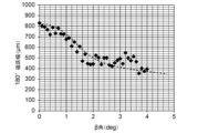
- FIG. It is a graph showing the relationship between the magnetic domain width before laser irradiation and the magnetic domain width after laser irradiation. It is a graph showing the relationship between the ⁇ angle and the average width of 180° magnetic domains of grain-oriented electrical steel sheets.
- the grain-oriented electrical steel sheet 50 has a stress introduction line 90, that is, a portion where tensile stress exists in the thickness direction.
- the tensile stress existing in the plate thickness direction is a component in the plate thickness direction of the tensile stress introduced into the grain-oriented electrical steel sheet 50 using the apparatus illustrated in FIG. 5 or the like.
- the number of measurement points is, for example, 10. If the tensile stress in the thickness direction is 40 MPa or more in at least one location of the grain-oriented electrical steel sheet 50, the maximum value of the tensile stress in the thickness direction at the stress treatment line of the grain-oriented electrical steel sheet 50 is 40 MPa or more. It is determined that there is. The measurement of the tensile stress may be stopped when a measurement point where the tensile stress in the plate thickness direction is 40 MPa or more is discovered.
- the magnetic domain control processed line 52 determines whether For example, if the length of one magnetic domain control processed line 52 included in the sample is X cm, and the number of stress introduction lines 90 included in the magnetic domain control processed line 52 is y, then the magnetic domain control processed line 52, it is determined that there are stress introduction lines 90 at y/X locations on average per 1 cm. Furthermore, whether or not the standard deviation of the length of the non-magnetic domain refining process line is 20 ⁇ m or less in each of the magnetic domain control process lines 52 that are determined to include stress introducing lines 90 at 10 or more locations per 1 cm on average. Determine.
- the plate thickness is 0.20 mm
- the magnetic flux density B8 when excited at 800 A/m is 1.87 T or more
- the excitation frequency is 50 Hz
- the iron loss measured at an excitation magnetic flux density of 1.7 T is 0.
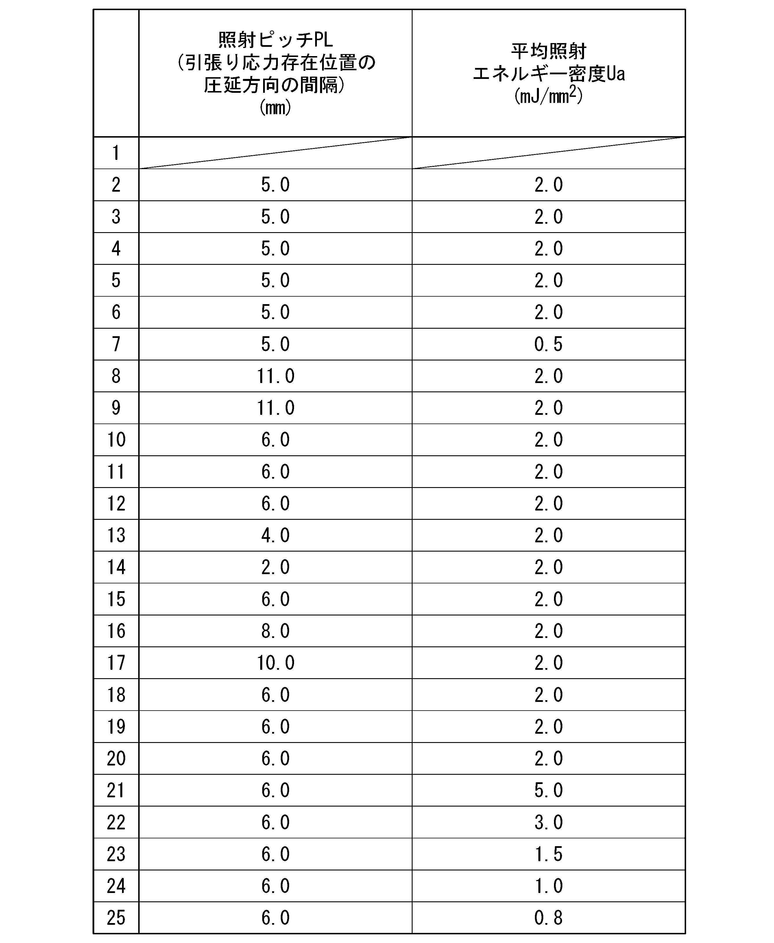
- Magnetic domain refining treatment was carried out under various conditions shown in Table 1 on the same lot of grain-oriented electrical steel sheets having a power of 80 W/kg or less.
- the irradiation pitch PL, the average irradiation energy density Ua, and the angle between the magnetic domain control processing line and the direction perpendicular to the rolling direction were set to constant values.
- the noise and iron loss of the grain-oriented electrical steel sheet that had been subjected to magnetic domain refining treatment thus obtained were evaluated and are listed in Tables 2 and 3. In Table 2, inappropriate values are underlined.
- Example where the tensile stress existence ratio in the first region is inappropriate stress was uniformly introduced.
- the tensile stress presence ratio in both the first region and the second region was set to a low level.
- noise was suppressed to a low level, but low iron loss was not achieved.
Landscapes
- Engineering & Computer Science (AREA)
- Chemical & Material Sciences (AREA)
- Physics & Mathematics (AREA)
- Power Engineering (AREA)
- Materials Engineering (AREA)
- Organic Chemistry (AREA)
- Metallurgy (AREA)
- Mechanical Engineering (AREA)
- Manufacturing & Machinery (AREA)
- Electromagnetism (AREA)
- Crystallography & Structural Chemistry (AREA)
- Thermal Sciences (AREA)
- Dispersion Chemistry (AREA)
- Optics & Photonics (AREA)
- Manufacturing Of Steel Electrode Plates (AREA)
Abstract
Description
本願は、2022年3月28日に、日本に出願された特願2022-052344号に基づき優先権を主張し、その内容をここに援用する。
具体的には、特許文献2の技術では、方向性電磁鋼板に磁区細分化処理を施すに際して、仕上焼鈍時のコイルの内巻部分から外巻部分に向けて、鋼板部分に照射するレーザのエネルギー密度を高めていく。特許文献2は、曲率半径が大きくなるとβ角の影響で磁区幅が広くなる領域が増加する旨を開示している。
特許文献4は、磁区細分化処理を施した方向性電磁鋼板であって、β角が0.5°以下の領域と2°~6°の領域を所定量含んでいる鉄損特性と磁歪特性の良好な方向性電磁鋼板を開示している。
特許文献5は、方向性電磁鋼板の磁区細分化の手法として引張応力を付与する旨を開示している。特許文献5には、磁区細分化を促進させ、鉄損を低減するために、鋼板内部に付与される板厚方向に対する引張応力は、最大値が40MPa以上で鋼板素材の降伏応力以下であることが記載されている。
(2)好ましくは、上記(1)に記載の方向性電磁鋼板では、前記引張り応力存在割合が、前記β角が1°超2°以下の領域である第3領域では20%以上80%以下であり、前記第1領域の前記引張り応力存在割合≧前記第3領域の前記引張り応力存在割合≧前記第2領域の前記引張り応力存在割合である。
(3)好ましくは、上記(1)又は(2)に記載の方向性電磁鋼板では、前記板厚方向に対して前記引張り応力が存在する前記部分は、圧延方向に10.0mm以下の間隔で存在する。
(5)好ましくは、上記(4)に記載の方向性電磁鋼板の製造方法では、前記決定ステップは、前記磁区制御処理線のうち、前記β角が1°以下の箇所を、前記引張り応力を導入する箇所として決定する。
(6)好ましくは、上記(4)又は(5)に記載の方向性電磁鋼板の製造方法では、前記決定ステップは、2次元フーリエ変換を用いて、前記磁区画像から前記引張り応力を導入する箇所を決定する。
(A-1)磁区画像から複数の部分領域を切り出すステップ;
(A-2)ST2DFTを行うステップ;
(A-3)磁区幅の空間分布を導出するステップ.
以下、各ステップについて詳細に説明する。
磁区画像から複数の部分領域を切り出して、それぞれの周波数構造を分析するために、k方向の範囲を0≦k≦Nk-1、l方向の範囲を0≦l≦Nl-1とした矩形窓の窓関数Wa(k,l)を用いる(Nk及びNlは自然数)。窓関数Wa(k,l)としては、Hamming窓、Hanning窓、Blackman窓などが適用可能である。

部分領域のデータ列をxnm(n´, m´)=xnm(k-nSk,l-mSl)と定義し、xnm(n´, m´)に対して2次元フーリエ変換を施すと、式(2)のように、観察位置(n,m)の部分領域に対応する部分フーリエ画像X(fk,fl,n,m)が得られる。

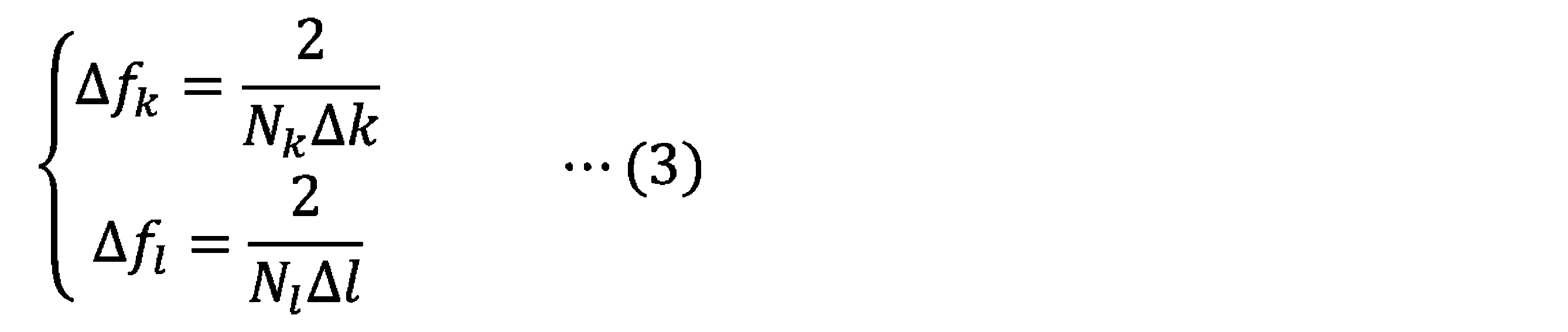
部分フーリエ画像X(fk,fl,n,m)が得られると、部分フーリエ画像X(fk,fl,n,m)のスポットのピーク位置の座標(k成分fk max(n,m)及びl成分fl max(n,m))が求められる。なお、ピーク位置の導出について、k=0、l=0の近傍の領域は、画像のコントラストに大きく依存する部分であるため、除外する。

本実施形態に係る方向性電磁鋼板50は、図9に例示されるように、応力導入線90、即ち板厚方向に対して引張り応力が存在する部分を有する。板厚方向に対して存在する引張り応力とは、図5に例示される装置などを用いて方向性電磁鋼板50に導入される引張り応力のうち、板厚方向の成分のことである。
応力導入線90は、図9に例示されるように、磁区制御処理線52上に配されている。磁区制御処理線52は、方向性電磁鋼板50の表面において、圧延直角方向(TD)に対して0°~45°の角度をなし、圧延方向(RD)に沿って並べられている。磁区制御処理線52は、互いに平行に並べられていることが好ましい。磁区制御処理線52は、方向性電磁鋼板50の製造段階におけるレーザビームLBの焦点の軌跡に対応する。磁区制御処理線52は、方向性電磁鋼板50において実体として存在するものではなく、応力導入線90に沿った仮想線である。応力導入線90に沿って線を引くこと等により、磁区制御処理線52を特定することができる。圧延直角方向(TD)と応力導入線90の延在方向とがなす角度は、圧延直角方向(TD)と、当該応力導入線90が設けられた磁区制御処理線52の延在方向とがなす角度と同一である。
また、鉄損を低減する効果を一層高めるため、圧延方向(RD)に沿って測定される、隣り合う磁区制御処理線52の間隔Pを10.0mm以下とすることが好ましい。すなわち、最大値が40MPa以上の引張り応力が、圧延方向(RD)に10.0mm以下の間隔で存在することが好ましい。なお、方向性電磁鋼板において、磁区制御処理線52の間隔Pは一様であってもよいし、ばらついていてもよい。方向性電磁鋼板の一部のみにおいて隣り合う磁区制御処理線52の間隔Pを10.0mm以下としてもよいし、方向性電磁鋼板の全ての領域において隣り合う磁区制御処理線52の間隔Pを10.0mm以下としてもよい。また、方向性電磁鋼板における隣り合う磁区制御処理線52の間隔Pの平均値を10.0mm以下としてもよい。隣り合う磁区制御処理線52の間隔P、又は磁区制御処理線52の間隔Pの平均値を1.0mm以上、2.0mm以上、3.0mm以上、又は5.0mm以上としてもよい。隣り合う磁区制御処理線52の間隔P、又は磁区制御処理線52の間隔Pの平均値を9.0mm以下、8.0mm以下、又は7.0mm以下としてもよい。
第1領域の引張り応力存在割合≧第3領域の引張り応力存在割合≧第2領域の引張り応力存在割合
第3領域を、β角が1.0°超2.0°以下の領域、β角が1.1°以上1.9°以下の領域、又はβ角が1.2°以上1.8°以下の領域と定義してもよい。
以下に、本実施形態に係る方向性電磁鋼板50に関するパラメータの測定方法について説明する。なお、いずれのパラメータの測定も、方向性電磁鋼板50から採取された所定サイズの試料に対して行われる。例えば、両辺の長さが100mm(又は100mm以上)の矩形試料を、方向性電磁鋼板50から切り出して、測定に供することができる。方向性電磁鋼板50がコイルである場合は、コイルの任意の箇所から試料を採取すればよい。また、方向性電磁鋼板50が、変圧器やモータなどの電機製品に組み込まれた部品とされている場合も、当該部品の任意の箇所から試料を採取すればよい。部品のサイズが小さい場合、試料の1辺の長さを100mm未満としてもよい。この場合、試料面積の合計値が10000mm2以上となるようにする。その際、試料に機械歪み等の影響を最小とするためワイヤーカット加工等の方法で試料を採取することが望ましい。
磁区制御処理線52と圧延直角方向(TD)とがなす角度の測定方法は以下の通りである。
(1)試料が、コイル状の方向性電磁鋼板50から切り出されたものである場合、方向性電磁鋼板50の幅方向が圧延直角方向(TD)であるとみなすことができる。
(2)試料が、電機製品の部品等から切り出されたものである場合、圧延直角方向(TD)を方向性電磁鋼板50の表面の圧延疵から特定する。圧延疵の延在方向を圧延方向(RD)とみなし、圧延方向(RD)に垂直且つ鋼板表面に平行な方向を、圧延直角方向(TD)とみなす。
(3)方向性電磁鋼板50の表面の圧延疵からの圧延直角方向(TD)の特定が困難である場合、圧延直角方向(TD)を方向性電磁鋼板50の結晶方位から特定する。具体的には、評価対象となる方向性電磁鋼板50の結晶方位を複数点で測定する。そして、当該測定点におけるGOSS方位からのずれ角が最小となる方向を、圧延方向(RD)とみなし、圧延方向(RD)に垂直且つ方向性電磁鋼板50の表面に平行な方向を、圧延直角方向(TD)とみなす。
いずれの場合も、測定の便宜の観点から、試料の一辺と圧延直角方向(TD)とが一致するように試料を方向性電磁鋼板50から切り出すことが好ましい。
方向性電磁鋼板50におけるβ角の測定は、側面反射ラウエ法によって行う。側面反射ラウエ法は、結晶方位の測定方法として広く知られている。
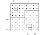
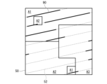
第1領域、第2領域、及び第3領域の特定方法は以下の通りである。図10に例示されるように、まず、試料の表面に仮想的な格子Lを設定する。これにより、試料の表面を、格子Lによって区切られた複数のセルCとして分割する。セルCの形状は、例えば1辺2mmの正方形とする。そして、セルCそれぞれの中心を測定点として、実側面反射ラウエ法による結晶方位の測定を実施する。これにより、測定点のβ角を特定し、測定点が第1領域A1、第2領域A2、及び第3領域A3のいずれに属するかを判定する。そして、中心が第1領域A1であると判定されたセルCは、その全体にわたって第1領域A1であるとみなす。同様に、中心が第2領域A2であると判定されたセルCは、その全体にわたって第2領域A2であるとみなし、中心が第3領域A3であると判定されたセルCは、その全体にわたって第3領域A3であるとみなす。図10においては、第1領域A1であるとみなされた測定点を黒色の丸印P1として表記し、第2領域A2であるとみなされた測定点を灰色の丸印P2として表記し、第3領域A3であるとみなされた測定点を黒色の丸印P3として表記している。上述の手順により、図10及び図11に示されるように、方向性電磁鋼板50の表面における第1領域A1、第2領域A2、及び第3領域A3を特定することができる。
磁区制御処理線52と圧延直角方向(TD)とがなす角度の測定方法の説明において示された手順により、図11に示されるように、第1領域A1、第2領域A2、及び第3領域A3にそれぞれにおける磁区制御処理線52及び応力導入線90を特定する。試料の全ての第1領域A1に含まれる全ての応力導入線90の合計長さを、試料の全ての第1領域A1に含まれる全ての磁区制御処理線52で割った値が、第1領域A1における引張り応力存在割合である。同様に、試料の全ての第2領域A2に含まれる全ての応力導入線90の合計長さを、試料の全ての第2領域A2に含まれる全ての磁区制御処理線52で割った値が、第2領域A2における引張り応力存在割合であり、試料の全ての第3領域A3に含まれる全ての応力導入線90の合計長さを、試料の全ての第3領域A3に含まれる全ての磁区制御処理線52で割った値が、第3領域A3における引張り応力存在割合である。
応力導入線90における、板厚方向に対する引張り応力の大きさは、EBSD Wilkinson法およびBLG Vantage社製Cross Courtにより測定する。EBSD Wilkinson法は、A. J.Wilkinson, et al.「High-resolution elastic strain measurement from electron backscatter diffraction patterns:New levels of sensitivity」Ultramicroscopy Vol 106,No.4-5,March 2006,P.307-313に詳細に説明されている。


例2では、磁区制御処理線と圧延直角方向がなす角度が過剰であった。例2においては、騒音評価結果が悪化した一方で、低鉄損化が達成されなかった。
例3及び例4では、応力の導入を均一的に行った。そして、例3及び例4では、第1領域及び第2領域の両方における引張り応力存在割合が低い水準とされた。例3及び例4においては、騒音は低い水準に抑制されていたが、低鉄損化が達成されなかった。
例5及び例6では、応力の導入を均一的に行った。そして、例5及び例6では、第1領域及び第2領域の両方における引張り応力存在割合が高い水準とされた。例3及び例4においては、低鉄損化が達成されていたが、低騒音化は達成されなかった。
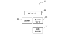
31 光源部
33 MOセンサ
35 イメージセンサ
37 信号処理部
40 解析装置
41 演算部
43 メモリ
45 表示部
47 入力部
49 通信I/F
50 方向性電磁鋼板
52 磁区制御処理線
90 応力導入線(板厚方向に対して引張り応力が存在する部分)
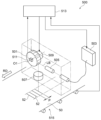
500 レーザ照射装置
L 格子
C セル
A1 第1領域
A2 第2領域
A3 第3領域
P1 第1領域と判定された測定点
P2 第2領域と判定された測定点
P3 第3領域と判定された測定点
RD 圧延方向
TD 圧延直角方向
Claims (6)
- 方向性電磁鋼板の表面において、圧延直角方向に対して0°~45°の角度をなし、且つ圧延方向に並ぶ磁区制御処理線の総延長のうち、非単一周期で存在し、板厚方向に対して引張り応力が存在する部分の占める割合である引張り応力存在割合が、圧延直角方向の軸まわりにおける結晶粒のGoss方位からのずれ角であるβ角が1°以下の領域である第1領域では50%以上であり、
前記引張り応力存在割合が、前記β角が2°超の領域である第2領域では50%未満であり、
前記引張り応力は、最大値が40MPa以上である、
方向性電磁鋼板。 - 前記引張り応力存在割合が、前記β角が1°超2°以下の領域である第3領域では20%以上80%以下であり、
前記第1領域の前記引張り応力存在割合≧前記第3領域の前記引張り応力存在割合≧前記第2領域の前記引張り応力存在割合である、請求項1に記載の方向性電磁鋼板。 - 前記板厚方向に対して前記引張り応力が存在する前記部分は、圧延方向に10.0mm以下の間隔で存在する、請求項1又は2に記載の方向性電磁鋼板。
- 方向性電磁鋼板の磁区画像を取得する画像取得ステップと、
前記磁区画像の磁区幅の空間分布と、圧延直角方向の軸まわりにおける結晶粒のGoss方位からのずれ角であるβ角とに基づいて、前記方向性電磁鋼板の圧延直角方向に対して0°~45°の角度をなし、且つ圧延方向に並ぶ磁区制御処理線のうち、引張り応力を導入する箇所を決定する決定ステップと、
前記磁区制御処理線のうち、前記決定ステップで決定された箇所に前記引張り応力を導入する応力導入ステップと、
を含む、方向性電磁鋼板の製造方法。 - 前記決定ステップは、前記磁区制御処理線のうち、前記β角が1°以下の箇所を、前記引張り応力を導入する箇所として決定する、請求項4に記載の方向性電磁鋼板の製造方法。
- 前記決定ステップは、2次元フーリエ変換を用いて、前記磁区画像から前記引張り応力を導入する箇所を決定する、請求項4又は5に記載の方向性電磁鋼板の製造方法。
Priority Applications (5)
| Application Number | Priority Date | Filing Date | Title |
|---|---|---|---|
| KR1020247026899A KR102871723B1 (ko) | 2022-03-28 | 2023-03-27 | 방향성 전자 강판 및 그 제조 방법 |
| JP2024512451A JPWO2023190328A1 (ja) | 2022-03-28 | 2023-03-27 | |
| US18/726,373 US20250243558A1 (en) | 2022-03-28 | 2023-03-27 | Grain-oriented electrical steel sheet and manufacturing method therefor |
| CN202380021779.2A CN118696142A (zh) | 2022-03-28 | 2023-03-27 | 方向性电磁钢板及其制造方法 |
| EP23780338.2A EP4502188A4 (en) | 2022-03-28 | 2023-03-27 | GRAIN-ORIENTED ELECTRICAL STEEL SHEET AND METHOD FOR PRODUCING SAME |
Applications Claiming Priority (2)
| Application Number | Priority Date | Filing Date | Title |
|---|---|---|---|
| JP2022052344 | 2022-03-28 | ||
| JP2022-052344 | 2022-03-28 |
Publications (1)
| Publication Number | Publication Date |
|---|---|
| WO2023190328A1 true WO2023190328A1 (ja) | 2023-10-05 |
Family
ID=88202353
Family Applications (1)
| Application Number | Title | Priority Date | Filing Date |
|---|---|---|---|
| PCT/JP2023/012179 Ceased WO2023190328A1 (ja) | 2022-03-28 | 2023-03-27 | 方向性電磁鋼板及びその製造方法 |
Country Status (6)
| Country | Link |
|---|---|
| US (1) | US20250243558A1 (ja) |
| EP (1) | EP4502188A4 (ja) |
| JP (1) | JPWO2023190328A1 (ja) |
| KR (1) | KR102871723B1 (ja) |
| CN (1) | CN118696142A (ja) |
| WO (1) | WO2023190328A1 (ja) |
Cited By (1)
| Publication number | Priority date | Publication date | Assignee | Title |
|---|---|---|---|---|
| WO2025070781A1 (ja) * | 2023-09-27 | 2025-04-03 | 日本製鉄株式会社 | 方向性電磁鋼板、及び方向性電磁鋼板の製造方法 |
Citations (10)
| Publication number | Priority date | Publication date | Assignee | Title |
|---|---|---|---|---|
| JPS55119125A (en) * | 1979-03-05 | 1980-09-12 | Nippon Steel Corp | Manufacture of low iron loss one-directional silicon steel plate |
| JPH11293340A (ja) * | 1998-04-08 | 1999-10-26 | Kawasaki Steel Corp | 低鉄損方向性電磁鋼板及びその製造方法 |
| JP2006144058A (ja) | 2004-11-18 | 2006-06-08 | Nippon Steel Corp | 磁気特性の優れた方向性電磁鋼板およびその製造方法 |
| JP2008127632A (ja) | 2006-11-21 | 2008-06-05 | Nippon Steel Corp | 低鉄損一方向性電磁鋼板 |
| JP2012012664A (ja) | 2010-06-30 | 2012-01-19 | Jfe Steel Corp | 方向性電磁鋼板の製造方法 |
| JP2012057219A (ja) | 2010-09-09 | 2012-03-22 | Jfe Steel Corp | 方向性電磁鋼板およびその製造方法 |
| JP2012057218A (ja) * | 2010-09-09 | 2012-03-22 | Jfe Steel Corp | 方向性電磁鋼板およびその製造方法 |
| CN106282512A (zh) * | 2015-05-11 | 2017-01-04 | 宝山钢铁股份有限公司 | 低噪音变压器用取向硅钢片制造方法 |
| JP2020169373A (ja) * | 2019-04-05 | 2020-10-15 | 日本製鉄株式会社 | 方向性電磁鋼板 |
| JP2022052344A (ja) | 2020-09-23 | 2022-04-04 | オリオン機械工業株式会社 | 集積装置 |
-
2023
- 2023-03-27 WO PCT/JP2023/012179 patent/WO2023190328A1/ja not_active Ceased
- 2023-03-27 KR KR1020247026899A patent/KR102871723B1/ko active Active
- 2023-03-27 US US18/726,373 patent/US20250243558A1/en active Pending
- 2023-03-27 EP EP23780338.2A patent/EP4502188A4/en active Pending
- 2023-03-27 CN CN202380021779.2A patent/CN118696142A/zh active Pending
- 2023-03-27 JP JP2024512451A patent/JPWO2023190328A1/ja active Pending
Patent Citations (11)
| Publication number | Priority date | Publication date | Assignee | Title |
|---|---|---|---|---|
| JPS55119125A (en) * | 1979-03-05 | 1980-09-12 | Nippon Steel Corp | Manufacture of low iron loss one-directional silicon steel plate |
| JPH11293340A (ja) * | 1998-04-08 | 1999-10-26 | Kawasaki Steel Corp | 低鉄損方向性電磁鋼板及びその製造方法 |
| JP2006144058A (ja) | 2004-11-18 | 2006-06-08 | Nippon Steel Corp | 磁気特性の優れた方向性電磁鋼板およびその製造方法 |
| JP2008127632A (ja) | 2006-11-21 | 2008-06-05 | Nippon Steel Corp | 低鉄損一方向性電磁鋼板 |
| JP5241095B2 (ja) | 2006-11-21 | 2013-07-17 | 新日鐵住金株式会社 | 低鉄損一方向性電磁鋼板 |
| JP2012012664A (ja) | 2010-06-30 | 2012-01-19 | Jfe Steel Corp | 方向性電磁鋼板の製造方法 |
| JP2012057219A (ja) | 2010-09-09 | 2012-03-22 | Jfe Steel Corp | 方向性電磁鋼板およびその製造方法 |
| JP2012057218A (ja) * | 2010-09-09 | 2012-03-22 | Jfe Steel Corp | 方向性電磁鋼板およびその製造方法 |
| CN106282512A (zh) * | 2015-05-11 | 2017-01-04 | 宝山钢铁股份有限公司 | 低噪音变压器用取向硅钢片制造方法 |
| JP2020169373A (ja) * | 2019-04-05 | 2020-10-15 | 日本製鉄株式会社 | 方向性電磁鋼板 |
| JP2022052344A (ja) | 2020-09-23 | 2022-04-04 | オリオン機械工業株式会社 | 集積装置 |
Non-Patent Citations (2)
| Title |
|---|
| A.J.WILKINSON ET AL.: "High-resolution elastic strain measurement from electron backscatter diffraction patterns: New levels of sensitivity", ULTRAMICROSCOPY, vol. 106, 4 March 2006 (2006-03-04), pages 307 - 313, XP025025471, DOI: 10.1016/j.ultramic.2005.10.001 |
| See also references of EP4502188A4 |
Cited By (1)
| Publication number | Priority date | Publication date | Assignee | Title |
|---|---|---|---|---|
| WO2025070781A1 (ja) * | 2023-09-27 | 2025-04-03 | 日本製鉄株式会社 | 方向性電磁鋼板、及び方向性電磁鋼板の製造方法 |
Also Published As
| Publication number | Publication date |
|---|---|
| EP4502188A4 (en) | 2025-07-16 |
| KR102871723B1 (ko) | 2025-10-17 |
| JPWO2023190328A1 (ja) | 2023-10-05 |
| EP4502188A1 (en) | 2025-02-05 |
| KR20240136374A (ko) | 2024-09-13 |
| US20250243558A1 (en) | 2025-07-31 |
| CN118696142A (zh) | 2024-09-24 |
Similar Documents
| Publication | Publication Date | Title |
|---|---|---|
| US20250118469A1 (en) | Grain-oriented electrical steel sheet and manufacturing method therefor | |
| WO2023190339A1 (ja) | 方向性電磁鋼板及びその製造方法 | |
| KR102871723B1 (ko) | 방향성 전자 강판 및 그 제조 방법 | |
| WO2025070780A1 (ja) | 方向性電磁鋼板、及び方向性電磁鋼板の製造方法 | |
| RU2841654C2 (ru) | Лист электротехнической стали с ориентированной зеренной структурой и способ его изготовления | |
| JP7817657B2 (ja) | 方向性電磁鋼板及びその製造方法 | |
| RU2840516C2 (ru) | Лист электротехнической стали с ориентированной зеренной структурой и способ его изготовления | |
| RU2846912C2 (ru) | Лист электротехнической стали с ориентированной зеренной структурой и способ его изготовления | |
| WO2025070785A1 (ja) | 方向性電磁鋼板 | |
| WO2025070790A1 (ja) | 方向性電磁鋼板、及び方向性電磁鋼板の製造方法 | |
| JP7836023B2 (ja) | 方向性電磁鋼板及びその製造方法 | |
| WO2025070793A1 (ja) | 方向性電磁鋼板及びその製造方法 | |
| WO2025070776A1 (ja) | 方向性電磁鋼板、及び方向性電磁鋼板の製造方法 | |
| KR20260057131A (ko) | 방향성 전자 강판, 및 방향성 전자 강판의 제조 방법 | |
| WO2025070786A1 (ja) | 方向性電磁鋼板及びその製造方法 | |
| CN118688583A (zh) | 一种基于阈值函数与变密度网格的局部放电超声检测方法 |
Legal Events
| Date | Code | Title | Description |
|---|---|---|---|
| 121 | Ep: the epo has been informed by wipo that ep was designated in this application |
Ref document number: 23780338 Country of ref document: EP Kind code of ref document: A1 |
|
| WWE | Wipo information: entry into national phase |
Ref document number: 2024512451 Country of ref document: JP |
|
| WWE | Wipo information: entry into national phase |
Ref document number: 202417050561 Country of ref document: IN Ref document number: 18726373 Country of ref document: US |
|
| REG | Reference to national code |
Ref country code: BR Ref legal event code: B01A Ref document number: 112024013603 Country of ref document: BR |
|
| ENP | Entry into the national phase |
Ref document number: 20247026899 Country of ref document: KR Kind code of ref document: A |
|
| WWE | Wipo information: entry into national phase |
Ref document number: 202380021779.2 Country of ref document: CN |
|
| ENP | Entry into the national phase |
Ref document number: 112024013603 Country of ref document: BR Kind code of ref document: A2 Effective date: 20240702 |
|
| WWE | Wipo information: entry into national phase |
Ref document number: 2023780338 Country of ref document: EP Ref document number: 2024128162 Country of ref document: RU |
|
| NENP | Non-entry into the national phase |
Ref country code: DE |
|
| ENP | Entry into the national phase |
Ref document number: 2023780338 Country of ref document: EP Effective date: 20241028 |
|
| WWG | Wipo information: grant in national office |
Ref document number: 2024128162 Country of ref document: RU |
|
| WWP | Wipo information: published in national office |
Ref document number: 18726373 Country of ref document: US |