WO2023190533A1 - 塗装方法および塗装装置 - Google Patents
塗装方法および塗装装置 Download PDFInfo
- Publication number
- WO2023190533A1 WO2023190533A1 PCT/JP2023/012554 JP2023012554W WO2023190533A1 WO 2023190533 A1 WO2023190533 A1 WO 2023190533A1 JP 2023012554 W JP2023012554 W JP 2023012554W WO 2023190533 A1 WO2023190533 A1 WO 2023190533A1
- Authority
- WO
- WIPO (PCT)
- Prior art keywords
- mode
- coating
- area
- painted
- painting
- Prior art date
- Legal status (The legal status is an assumption and is not a legal conclusion. Google has not performed a legal analysis and makes no representation as to the accuracy of the status listed.)
- Ceased
Links
Images





Classifications
-
- B—PERFORMING OPERATIONS; TRANSPORTING
- B05—SPRAYING OR ATOMISING IN GENERAL; APPLYING FLUENT MATERIALS TO SURFACES, IN GENERAL
- B05D—PROCESSES FOR APPLYING FLUENT MATERIALS TO SURFACES, IN GENERAL
- B05D1/00—Processes for applying liquids or other fluent materials
- B05D1/26—Processes for applying liquids or other fluent materials performed by applying the liquid or other fluent material from an outlet device in contact with, or almost in contact with, the surface
-
- B—PERFORMING OPERATIONS; TRANSPORTING
- B05—SPRAYING OR ATOMISING IN GENERAL; APPLYING FLUENT MATERIALS TO SURFACES, IN GENERAL
- B05B—SPRAYING APPARATUS; ATOMISING APPARATUS; NOZZLES
- B05B12/00—Arrangements for controlling delivery; Arrangements for controlling the spray area
- B05B12/14—Arrangements for controlling delivery; Arrangements for controlling the spray area for supplying a selected one of a plurality of liquids or other fluent materials or several in selected proportions to a spray apparatus, e.g. to a single spray outlet
- B05B12/1418—Arrangements for controlling delivery; Arrangements for controlling the spray area for supplying a selected one of a plurality of liquids or other fluent materials or several in selected proportions to a spray apparatus, e.g. to a single spray outlet for supplying several liquids or other fluent materials in selected proportions to a single spray outlet
-
- B—PERFORMING OPERATIONS; TRANSPORTING
- B05—SPRAYING OR ATOMISING IN GENERAL; APPLYING FLUENT MATERIALS TO SURFACES, IN GENERAL
- B05B—SPRAYING APPARATUS; ATOMISING APPARATUS; NOZZLES
- B05B12/00—Arrangements for controlling delivery; Arrangements for controlling the spray area
- B05B12/02—Arrangements for controlling delivery; Arrangements for controlling the spray area for controlling time, or sequence, of delivery
- B05B12/04—Arrangements for controlling delivery; Arrangements for controlling the spray area for controlling time, or sequence, of delivery for sequential operation or multiple outlets
-
- B—PERFORMING OPERATIONS; TRANSPORTING
- B05—SPRAYING OR ATOMISING IN GENERAL; APPLYING FLUENT MATERIALS TO SURFACES, IN GENERAL
- B05B—SPRAYING APPARATUS; ATOMISING APPARATUS; NOZZLES
- B05B13/00—Machines or plants for applying liquids or other fluent materials to surfaces of objects or other work by spraying, not covered by groups B05B1/00 - B05B11/00
- B05B13/002—Machines or plants for applying coating liquids or other fluent materials by inkjet
-
- B—PERFORMING OPERATIONS; TRANSPORTING
- B05—SPRAYING OR ATOMISING IN GENERAL; APPLYING FLUENT MATERIALS TO SURFACES, IN GENERAL
- B05B—SPRAYING APPARATUS; ATOMISING APPARATUS; NOZZLES
- B05B13/00—Machines or plants for applying liquids or other fluent materials to surfaces of objects or other work by spraying, not covered by groups B05B1/00 - B05B11/00
- B05B13/02—Means for supporting work; Arrangement or mounting of spray heads; Adaptation or arrangement of means for feeding work
- B05B13/04—Means for supporting work; Arrangement or mounting of spray heads; Adaptation or arrangement of means for feeding work the spray heads being moved during spraying operation
- B05B13/0431—Means for supporting work; Arrangement or mounting of spray heads; Adaptation or arrangement of means for feeding work the spray heads being moved during spraying operation with spray heads moved by robots or articulated arms, e.g. for applying liquid or other fluent material to three-dimensional [3D] surfaces
-
- B—PERFORMING OPERATIONS; TRANSPORTING
- B05—SPRAYING OR ATOMISING IN GENERAL; APPLYING FLUENT MATERIALS TO SURFACES, IN GENERAL
- B05B—SPRAYING APPARATUS; ATOMISING APPARATUS; NOZZLES
- B05B13/00—Machines or plants for applying liquids or other fluent materials to surfaces of objects or other work by spraying, not covered by groups B05B1/00 - B05B11/00
- B05B13/02—Means for supporting work; Arrangement or mounting of spray heads; Adaptation or arrangement of means for feeding work
- B05B13/04—Means for supporting work; Arrangement or mounting of spray heads; Adaptation or arrangement of means for feeding work the spray heads being moved during spraying operation
- B05B13/0431—Means for supporting work; Arrangement or mounting of spray heads; Adaptation or arrangement of means for feeding work the spray heads being moved during spraying operation with spray heads moved by robots or articulated arms, e.g. for applying liquid or other fluent material to three-dimensional [3D] surfaces
- B05B13/0433—Means for supporting work; Arrangement or mounting of spray heads; Adaptation or arrangement of means for feeding work the spray heads being moved during spraying operation with spray heads moved by robots or articulated arms, e.g. for applying liquid or other fluent material to three-dimensional [3D] surfaces the work being vehicle components, e.g. vehicle bodies
-
- B—PERFORMING OPERATIONS; TRANSPORTING
- B05—SPRAYING OR ATOMISING IN GENERAL; APPLYING FLUENT MATERIALS TO SURFACES, IN GENERAL
- B05B—SPRAYING APPARATUS; ATOMISING APPARATUS; NOZZLES
- B05B15/00—Details of spraying plant or spraying apparatus not otherwise provided for; Accessories
- B05B15/20—Arrangements for agitating the material to be sprayed, e.g. for stirring, mixing or homogenising
-
- B—PERFORMING OPERATIONS; TRANSPORTING
- B05—SPRAYING OR ATOMISING IN GENERAL; APPLYING FLUENT MATERIALS TO SURFACES, IN GENERAL
- B05B—SPRAYING APPARATUS; ATOMISING APPARATUS; NOZZLES
- B05B15/00—Details of spraying plant or spraying apparatus not otherwise provided for; Accessories
- B05B15/50—Arrangements for cleaning; Arrangements for preventing deposits, drying-out or blockage; Arrangements for detecting improper discharge caused by the presence of foreign matter
-
- B—PERFORMING OPERATIONS; TRANSPORTING
- B05—SPRAYING OR ATOMISING IN GENERAL; APPLYING FLUENT MATERIALS TO SURFACES, IN GENERAL
- B05D—PROCESSES FOR APPLYING FLUENT MATERIALS TO SURFACES, IN GENERAL
- B05D5/00—Processes for applying liquids or other fluent materials to surfaces to obtain special surface effects, finishes or structures
- B05D5/06—Processes for applying liquids or other fluent materials to surfaces to obtain special surface effects, finishes or structures to obtain multicolour or other optical effects
- B05D5/065—Processes for applying liquids or other fluent materials to surfaces to obtain special surface effects, finishes or structures to obtain multicolour or other optical effects having colour interferences or colour shifts or opalescent looking, flip-flop, two tones
-
- B—PERFORMING OPERATIONS; TRANSPORTING
- B05—SPRAYING OR ATOMISING IN GENERAL; APPLYING FLUENT MATERIALS TO SURFACES, IN GENERAL
- B05D—PROCESSES FOR APPLYING FLUENT MATERIALS TO SURFACES, IN GENERAL
- B05D2490/00—Intermixed layers
- B05D2490/60—Intermixed layers compositions varying with a gradient parallel to the surface
-
- B—PERFORMING OPERATIONS; TRANSPORTING
- B05—SPRAYING OR ATOMISING IN GENERAL; APPLYING FLUENT MATERIALS TO SURFACES, IN GENERAL
- B05D—PROCESSES FOR APPLYING FLUENT MATERIALS TO SURFACES, IN GENERAL
- B05D7/00—Processes, other than flocking, specially adapted for applying liquids or other fluent materials to particular surfaces or for applying particular liquids or other fluent materials
- B05D7/14—Processes, other than flocking, specially adapted for applying liquids or other fluent materials to particular surfaces or for applying particular liquids or other fluent materials to metal, e.g. car bodies
-
- B—PERFORMING OPERATIONS; TRANSPORTING
- B41—PRINTING; LINING MACHINES; TYPEWRITERS; STAMPS
- B41J—TYPEWRITERS; SELECTIVE PRINTING MECHANISMS, i.e. MECHANISMS PRINTING OTHERWISE THAN FROM A FORME; CORRECTION OF TYPOGRAPHICAL ERRORS
- B41J3/00—Typewriters or selective printing or marking mechanisms characterised by the purpose for which they are constructed
- B41J3/407—Typewriters or selective printing or marking mechanisms characterised by the purpose for which they are constructed for marking on special material
- B41J3/4073—Printing on three-dimensional objects not being in sheet or web form, e.g. spherical or cubic objects
Definitions
- the disclosed embodiments relate to a coating method and a coating device.
- a coating device using an inkjet method is known.
- Such an inkjet coating device is equipped with a head for discharging coating material.
- a coating method coats a coating area of a surface to be coated using a head having a plurality of nozzles that discharge liquid.
- the painting method includes a step of painting in a first mode while moving the head in a direction along the edge of the painting area, and a step of painting in a second mode having a higher discharge rate than the first mode.
- a first area including at least a portion of the edge is painted in the first mode.
- the coating device coats the coating area.
- the coating device includes a head having a plurality of nozzles that eject liquid, and a control section that controls ejection of liquid from the plurality of nozzles.
- the coating device has a first mode in which coating is performed while moving the head in a direction along the edge of the coating area, and a second mode in which the discharge rate is higher than in the first mode.
- the control unit paints a first area including at least a portion of the edge in the first mode.
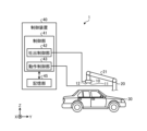
- FIG. 1 is an explanatory diagram of a coating apparatus according to an embodiment.
- FIG. 2 is a plan view of the head included in the coating apparatus according to the embodiment, viewed from the nozzle surface side.
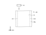
- FIG. 3 is a plan view showing a schematic configuration of the surface to be painted.
- FIG. 4 is a diagram illustrating the process of ejected liquid until it lands.
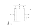
- FIG. 5 is a plan view showing an example of a first area and a second area of the painting area painted by the painting method according to the first embodiment.
- FIG. 6 is an explanatory diagram showing an example of the first mode of the coating device.
- FIG. 7 is a plan view showing an example of a painted area painted by the painting method according to the second embodiment.
- FIG. 8 is a plan view showing an example of a painted area painted by the painting method according to the third embodiment.
- FIG. 9 is a plan view showing an example of a painted area painted by the painting method according to the fourth embodiment.
- FIG. 10 is a plan view showing an example of a painted area painted by the painting method according to the fifth embodiment.
- FIG. 11 is a plan view showing an example of a painted area painted by the painting method according to the sixth embodiment.
- FIG. 12 is a plan view showing an example of a painted area painted by the painting method according to the seventh embodiment.
- FIG. 13 is a plan view showing an example of a painted area painted by the painting method according to the eighth embodiment.
- FIG. 14 is a plan view showing an example of a painted area painted by the painting method according to the ninth embodiment.
- FIG. 15 is a plan view showing an example of a painted area painted by the painting method according to the tenth embodiment.
- the above-mentioned coating equipment has room for further improvement in terms of improving coating quality. Therefore, it is expected to provide a coating method and a coating device that can improve coating quality.
- each embodiment can be combined as appropriate within the range that does not conflict with the processing contents. Further, in each of the embodiments below, the same parts are given the same reference numerals, and redundant explanations will be omitted.
- FIG. 1 is an explanatory diagram of a coating apparatus according to an embodiment.
- FIG. 1 shows a three-dimensional orthogonal coordinate system including a Z-axis with the vertically upward direction being the positive direction and the vertically downward direction being the negative direction.
- Such an orthogonal coordinate system may also be shown in other drawings used in the description below.
- the coating device 1 includes a head 10, a robot 20, and a control device 40.
- a head 10 for example, a valve-type, piezo-type, or thermal-type inkjet head can be used. If a piezo type or thermal type inkjet head is used as the head 10, high resolution can be easily achieved.
- the head 10 is fixed to the robot 20.
- the head 10 moves according to the operation of the robot 20 controlled by the control device 40.
- the head 10 has a plurality of nozzles 11.
- the surface on which the plurality of nozzles 11 are located is referred to as a nozzle surface 12.
- the head 10 coats the object 30 by making the liquid discharged from the plurality of nozzles 11 located on the nozzle surface 12 land on the surface of the object 30 facing the nozzle surface 12.
- Liquid is supplied to the head 10 from a tank (not shown).
- the head 10 discharges liquid supplied from a tank.
- a liquid is a mixture containing volatile components and non-volatile components, and has fluidity.
- the tank may be a reservoir (not shown) housed in the head 10.
- the volatile component is, for example, water, an organic solvent, alcohol, etc., and adjusts the physical properties of the liquid, such as viscosity and surface tension.
- Nonvolatile components include, for example, pigments, resin materials, and additives. Pigments include one or more colored pigments used depending on the desired paint color.
- the resin material adheres to the object 30 to form a film.
- the additive is a functional material added for the purpose of weather resistance, for example.
- Such non-volatile components may be dissolved in the volatile components, or may be dispersed without being dissolved. In this way, the liquid discharged from the nozzle 11 is a coating material prepared by mixing a plurality of components so as to develop a desired coating color.
- the robot 20 holds the head 10.
- the robot 20 is, for example, a six-axis articulated robot.
- the robot 20 may be, for example, a vertically articulated robot or a horizontally articulated robot.
- the robot 20 has a plurality of arms 21, and the head 10 is fixed to the tip of the arm 21.
- the robot 20 is fixed to a floor, wall, ceiling, or the like. Note that there is no limit to the degree of freedom of the arm 21 of the robot 20 as long as the held head 10 can be moved appropriately.
- the control device 40 controls the coating device 1.
- the control device 40 includes a control section 41 that controls the coating device 1 and a storage section 45.
- the control section 41 includes a discharge control section 42 and an operation control section 43.
- the control unit 41 includes, for example, a computer having a CPU (Central Processing Unit), a ROM (Read Only Memory), a RAM (Random Access Memory), an HDD (Hard Desk Drive), an input/output port, and various circuits.
- the CPU of such a computer functions as the control unit 41 by reading and executing a program stored in a ROM, for example.
- the control unit 41 may be configured with hardware such as an ASIC (Application Specific Integrated Circuit) or an FPGA (Field Programmable Gate Array).
- the discharge control unit 42 controls the head 10 based on the setting information stored in the storage unit 45 and causes the plurality of nozzles 11 to discharge liquid toward the object 30 to be coated.
- the operation control section 43 controls the operations of the plurality of arms 21 based on the setting information stored in the storage section 45, and controls the movement of the head 10 via the arms 21.
- the distance between the head 10 and the object to be coated 30 is maintained at, for example, about 0.5 mm to 20 mm. Note that detailed movements of the head 10 including liquid ejection will be described later.
- the storage unit 45 corresponds to, for example, a ROM and an HDD.
- the ROM and HDD can store setting information for various controls in the control device 40.
- the storage unit 45 stores information regarding the control of ejection of coating material by the head 10. Furthermore, the storage unit 45 stores information regarding the operation control of the plurality of arms 21.
- the storage unit 45 may store data input by a user's teaching work using a terminal device (not shown) as teaching data for operating the robot 20. Further, the control unit 41 may acquire the setting information via another computer or a portable recording medium connected via a wired or wireless network.
- the object to be painted 30 is, for example, a car body.
- the object to be coated 30 is placed on a transport device (not shown) and is carried in and out.
- the coating apparatus 1 according to the embodiment coats the object to be coated 30 while the conveyance device is stopped.
- the coating device 1 may be used to paint the object 30 that is repeatedly transported and stopped, or may be used to paint the object 30 in parallel with the transportation of the object 30.
- FIG. 2 is a plan view of the head included in the coating apparatus according to the embodiment, viewed from the nozzle surface side.
- the head 10 has a substantially rectangular shape in plan view.
- the nozzle surface 12 has a first side 13 along the length direction of the head 10 and a second side 14 along the width direction of the head 10.
- the nozzles 11 are arranged in a column direction along the first side 13 and in a row direction crossing the column direction.
- the head 10 paints the object 30 by discharging the liquid while moving along the second side 14, that is, in the example shown in FIG. 2, along the Y-axis positive direction or the Y-axis negative direction.
- FIG. 3 is a plan view showing the schematic configuration of the object to be painted.
- the object to be painted 30 has a surface to be painted 30a.
- the head 10 paints a predetermined painting area 31 of the surface to be painted 30a.
- FIG. 4 is a diagram illustrating the process of ejected liquid until it lands.
- the liquid 50 discharged from the nozzle 11 of the head 10 lands as a droplet 51 on the coating area 31 of the surface to be coated 30a.
- the airflow 60 may deviate from directly below the nozzle 11 .
- the influence of the airflow 60 becomes significant, for example, when the distance g1 between the head 10 and the surface to be coated 30a is set to 5 mm or more.
- the liquid 50 discharged from the nozzle 11 is affected by the airflow 60, for example, an area including the edges 311 and 312 of the coating area 31 shown in FIG. 3 is coated using the head 10 that moves along the Y-axis direction.
- the landing of the droplets 51 for coating the edges 311 and 312 may vary and the coating quality may deteriorate.
- the linearity of the edges 311 and 312 may be disturbed, or the droplet 51 may land on the outside of the coating area 31, which tends to cause the coating quality to deteriorate.
- Such deterioration in coating quality becomes noticeable, for example, when the straightness is 70 ⁇ m or more, furthermore 100 ⁇ m or more.
- straightness refers to the distance from the virtual droplet 51a located directly below the nozzle 11 shown in FIG. 4 to the droplet 51 that actually landed.
- the coating device 1 sets the discharge rate of the liquid 50 discharged from the nozzle 11 to be different depending on whether the edges 311, 312 of the coating area 31 are coated or the other parts.
- the decision was made to control the Specifically, a first area including the edges 311 and 312 of the coating area 31 is painted in the first mode, and a second area not including the edges 311 and 312 is painted in the first mode, which has a higher discharge rate than the first mode. Paint in 2 modes. As a result, the edges 311 and 312 of the painted area 31 become sharp and look good. Therefore, according to the coating apparatus 1 according to the embodiment, coating quality can be improved.
- FIG. 5 is a plan view showing an example of a first area and a second area of the painting area painted by the painting method according to the first embodiment.
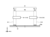
- FIG. 6 is an explanatory diagram showing an example of the first mode of the coating device.
- the coating device 1 coats the first region R1 including the edges 311 and 312 of the coating region 31 in the first mode.
- the first mode is a mode in which liquid 50 is ejected using some of the plurality of nozzles 11 of the head 10 and painting is performed without ejecting the liquid 50 from the remaining nozzles 11. It is.
- coating can be performed with the discharge rate in the first mode being 1% to 10%, and further 4% to 6%. If the discharge rate is less than 1%, for example, there is a possibility that the edges 311, 312 of the coating area 31 cannot be coated with good appearance.
- the discharge rate refers to the ratio of the nozzles 11 used for painting among the plurality of nozzles 11 shown in FIG.
- the ejection rate is 5%.
- ejection/non-ejection of the liquid 50 from the plurality of nozzles 11 may be controlled, for example, in units of rows, or may be controlled individually.
- the nozzles 11 that eject the liquid 50 may be continuous in the column direction and/or the row direction, or may be discontinuous.
- edges 311 and 312 are formed by droplets 51 that are ejected to the outermost side of the coating area 31, and are ejected from the nozzle 11 located at the outermost side of the coating area 31 among the nozzles 11 of the head 10. Ru.
- the edge portions 311 and 312 represent droplets 51 ejected from the 16th nozzle 11, which is 1% of the total, from the nozzle 11 located at the outermost position of the painting area 31 among the nozzles 11 of the head 10. It may be formed by.
- the region R1-1 of the first region R1 is a region where the droplets 51 land when the coating region 31 including the edge 311 of the coating region 31 is coated at a predetermined discharge rate using the head 10. be.
- the region R1-2 of the first region R1 is the region where the droplet 51 lands when the coating region 31 including the edge 312 of the coating region 31 is coated at a predetermined discharge rate using the head 10. It is.
- the second region R2 is a region of the painted region 31 that does not include the edges 311 and 312.
- the second region R2 according to this embodiment is a region other than the first region R1.
- the head 10 paints the second region R2 in the second mode, which has a higher discharge rate than the first mode. Specifically, coating can be performed with the discharge rate in the second mode being 90% or more, further 95% or more.
- the ejection rate in the second mode only needs to be higher than that in the first mode, and may be 50% or more.
- the influence of the airflow 60 on the liquid 50 discharged from the nozzle 11 can be reduced.
- the coating quality can be improved.
- the coating efficiency is less likely to decrease.
- control unit 41 may cause the coating to be applied in the order of the first area R1 ⁇ the second area R2, or may cause the coating to be applied in the order of the second area R2 ⁇ the first area R1. Further, the coating may be performed in the order of region R1-1 ⁇ second region R2 ⁇ region R1-2.
- control unit 41 may input a predetermined control signal to the liquid 50 in the nozzle 11 from which the liquid 50 is not ejected, and may cause the liquid 50 to vibrate. This makes it possible to prevent the nozzles 11 that are not used in the first mode from becoming clogged.
- waste discharge may be performed in which the liquid 50 located in the nozzle 11 that does not correspond to the first region R1 is discharged.
- the wasteful discharge includes, for example, discharging a small amount of liquid 50 to the second region R2.
- first region R1 and the second region R2 may be painted at the same speed, or may be painted at different speeds.
- the first area R1 may be painted at the same speed as the second area R2. This can reduce problems caused by, for example, timing discrepancies between the discharge speed from the nozzle 11 and the coating speed.
- FIG. 7 is a plan view showing an example of a painted area painted by the painting method according to the second embodiment.
- the object to be painted 30 shown in FIG. 7 has a rectangular painting area 31 on the surface to be painted 30a.
- the painting area 31 has edges 321 and 323 extending along the Y-axis direction and edges 322 and 324 extending along the X-axis direction.
- the coating device 1 coats the first region R1 including the edges 321 to 324 of the coating region 31 in the first mode.
- the first region R1 includes a region R11 including an edge 321, a region R12 including an edge 322, a region R13 including an edge 323, and a region R14 including an edge 324.
- Areas R11 and R13 are painted by a head 10-3 that moves along the Y-axis direction.
- Regions R12 and R14 are painted by a head 10-4 that moves along the X-axis direction.
- the first region R1 may include a first overlapping region S1 that is an overlapping region that is painted overlappingly in the first mode.
- the first overlapping region S1 may be coated multiple times while moving the head 10 in different directions.
- the second region R2 that does not include the edges 321 to 314 is painted in the second mode, which has a higher discharge rate than the first mode. This makes it difficult to reduce coating efficiency.
- the second region R2 may be painted by the head 10-3 that moves along the Y-axis direction, or may be painted by the head 10-4 that moves along the X-axis direction.
- control unit 41 may cause the painting areas 31 to be painted in any order.
- the control unit 41 may cause the coating to be applied in the order of the first area R1 ⁇ the second area R2, or may cause the coating to be applied in the order of the second area R2 ⁇ the first area R1.
- the control unit 41 may cause the first area R1 to be painted in the order of, for example, area R11 ⁇ area R12 ⁇ area R13 ⁇ area R14, or may cause the first area R1 to be painted in the order of area R11 ⁇ area R13 ⁇ area R12 ⁇ area R14. Good too.
- the control unit 41 may, for example, cause the mutually facing areas R11 and R13 to be coated at the same time, or may cause the areas R12 and R14 to be coated at the same time.
- first region R1 and the second region R2 may be painted at different speeds.
- the first area R1 may be painted at a higher speed than the second area R2.
- the first region R1 is painted in the first mode, for example, the liquid 50 adheres to the outside of the painting region 31 located near the edges 321 to 324, and the appearance of the edges 321 to 324 deteriorates. It is possible to reduce the number of defects that occur.
- the regions R11 to R14 may be painted at the same speed or may be painted at different speeds.
- FIG. 8 is a plan view showing an example of a painted area painted by the painting method according to the third embodiment.
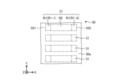
- the object to be painted 30 shown in FIG. 8 has a plurality of painting areas 31 arranged in the Y-axis direction on the surface to be painted 30a.
- the coating device 1 coats the area R1-1 of the first area R1 including the edge 331 of the coating area 31 in the first mode.
- the area R1-1 of the plurality of painting areas 31 is painted by the head 10 moving along the Y-axis direction.
- the coating device 1 coats the area R1-2 of the first area R1 including the edge 332 of the coating area 31 in the first mode.
- the area R1-1 of the plurality of painting areas 31 is painted by the head 10 moving along the Y-axis direction.
- the coating device 1 coats the second region R2 of the coating region 31 that does not include the edges 331 and 332 in the second mode.
- the second region R2 of the plurality of painting regions 31 is painted by the head 10 moving along the Y-axis direction.
- coating efficiency is improved by sequentially coating the plurality of coating areas 31 by moving the head 10 in one direction.
- FIG. 9 is a plan view showing an example of a painted area painted by the painting method according to the fourth embodiment.
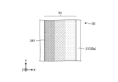
- the object 30 shown in FIG. 9 has a coating area 31 including the first area R1 on the coating surface 30a.
- the first region R1 includes an edge 341 extending along the Y-axis direction. Note that in FIG. 9, illustration of the second region R2 is omitted.
- the first region R1 is painted in the first mode while moving the head 10 in the direction along the edge 341.
- the first region R1 may be painted with a gradation coating whose brightness increases as the distance from the edge 341 increases.
- FIG. 10 is a plan view showing an example of a painted area painted by the painting method according to the fifth embodiment.
- the object to be painted 30 shown in FIG. 10 has a painting area 31 including the first area R1 on the painting surface 30a.
- the first region R1 has a region R11 including an edge 351 extending along the Y-axis direction and a region R12 including an edge 352 extending along the X-axis direction. Note that in FIG. 10, illustration of the second region R2 is omitted.
- the area R11 is painted in the first mode by the head 10 moving in the direction along the edge 351.
- the region R12 is painted in the first mode by the head 10 moving in the direction along the edge 352.
- the region R11 and/or the region R12 may be painted with a gradation coating whose brightness increases as the distance from the edge 351 side and/or edge 352 side increases. This makes it possible to appropriately reduce the number of droplets 51 that land on the first overlapping region S1 that is coated multiple times in the first mode, thereby improving the coating quality.
- FIG. 11 is a plan view showing an example of a painted area painted by the painting method according to the sixth embodiment.
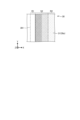
- the object 30 shown in FIG. 11 has a coating area 31 including a first area R1 and a second area R2 on a coating surface 30a.
- the first region R1 includes an edge 361 extending along the Y-axis direction.
- the second region R2 is painted in the second mode by the head 10 moving in the direction along the edge 361.
- the second region R2 may be painted with a gradation coating whose brightness increases as the distance from the edge 361 increases.
- FIG. 12 is a plan view showing an example of a painted area painted by the painting method according to the seventh embodiment.
- the object to be painted 30 shown in FIG. 12 has a painting area 31 including a first area R1, a second area R2, and a second overlapping area S2 on a painting surface 30a.
- the first region R1 includes an edge 371 extending along the Y-axis direction.
- the first region R1 is painted in the first mode while moving the head 10 in the direction along the edge 371.
- the second region R2 is painted in the second mode, which has a higher discharge rate than the first mode, while moving the head 10 in the direction along the edge 371.
- the second overlapping area S2 is an area that is painted in duplicate when it is painted in the first mode and when it is painted in the second mode. In this way, by locating the second overlapping region S2 between the first region R1 and the second region R2, the first region R1 to be painted in the first mode and the second region R2 to be painted in the second mode can be The border between the two surfaces becomes even more difficult to see, and the quality of the coating further improves. Note that in the example shown in FIG. 12, an example has been described in which the first region R1 and the second region R2 are painted in the same direction; however, the present invention is not limited to this; The second area R2 may be painted while applying the coating.
- FIGS. 13 to 15 are plan views showing examples of painted areas painted by the painting methods according to the eighth to tenth embodiments.
- a second overlapping region S2 is located between the first region R1 and the second region R2 in the painting region 31 of the surface to be painted 30a.
- the second overlapping region S2 may be painted with a gradation coating whose brightness increases as the distance from the edge 371 increases.
- gradation painting may be performed, for example, in a first mode in which the first region R1 is painted, or in a second mode in which the second region R2 is painted.
- gradation painting may be performed in both the first mode and the second mode.
- the second overlapping region S2 is formed when the first region R1 is painted with gradation painting (first gradation painting) whose brightness increases as the distance from the edge 381 increases. It may also be painted in the first mode. Further, as shown in FIG. 15, the second overlapping region S2 is formed when the second region R2 is painted with gradation painting (second gradation painting) whose brightness increases as the distance from the edge 391 increases. It may also be painted in the second mode.
- the present invention is not limited to the above embodiments, and various changes can be made without departing from the spirit thereof.
- the present invention is not limited to this.
- the number of droplets ejected in the first mode may be smaller than the number of droplets ejected in the second mode.
- the size of the droplets ejected in the first mode may be smaller than the size of the droplets ejected in the second mode.
- the coating area 31 of the surface to be coated 30a is coated using the head 10 having a plurality of nozzles 11 that discharge the liquid 50.
- the coating method includes a step of painting in a first mode while moving the head 10 in a direction along the edge of the painting area 31, and a step of painting in a second mode with a higher discharge rate than the first mode.
- a first region R1 including at least a portion of the edge is painted in a first mode.
- the coating device 1 coats the coating area 31.
- the coating device 1 includes a head 10 having a plurality of nozzles 11 that ejects a liquid 50, and a control section 41 that controls the ejection of the liquid 50 from the plurality of nozzles 11.
- the coating device 1 has a first mode in which painting is performed while moving the head 10 in a direction along the edge of the coating area 31, and a second mode in which the discharge rate is higher than in the first mode.
- the control unit 41 paints the first region R1 including at least a part of the edge of the painting region 31 in the first mode.
Landscapes
- Engineering & Computer Science (AREA)
- Robotics (AREA)
- Application Of Or Painting With Fluid Materials (AREA)
- Coating Apparatus (AREA)
Abstract
Description
<塗装装置の構成>
まず、図1を参照して実施形態に係る塗装装置の概要について説明する。図1は、実施形態に係る塗装装置の説明図である。なお、説明を分かりやすくするために、図1には、鉛直上向きを正方向とし、鉛直下向きを負方向とするZ軸を含む3次元の直交座標系を図示している。かかる直交座標系は、後述の説明に用いる他の図面でも示す場合がある。
(第1の実施形態)
次に、実施形態に係る塗装装置1が実行する塗装方法について、図5、図6を用いて説明する。図5は、第1の実施形態に係る塗装方法で塗装された塗装領域の第1領域および第2領域の一例を示す平面図である。図6は、塗装装置の第1モードの一例を示す説明図である。
図7は、第2の実施形態に係る塗装方法で塗装された塗装領域の一例を示す平面図である。図7に示す被塗装物30は、被塗装面30aに矩形状の塗装領域31を有している。塗装領域31は、Y軸方向に沿って延びる縁部321,323と、X軸方向に沿って延びる縁部322,324を有している。
図8は、第3の実施形態に係る塗装方法で塗装された塗装領域の一例を示す平面図である。図8に示す被塗装物30は、Y軸方向に並ぶ複数の塗装領域31を被塗装面30aに有している。
図9は、第4の実施形態係る塗装方法で塗装された塗装領域の一例を示す平面図である。図9に示す被塗装物30は、第1領域R1を含む塗装領域31を被塗装面30aに有する。第1領域R1は、Y軸方向に沿って延びる縁部341を含む。なお、図9では、第2領域R2の図示を省略している。
図10は、第5の実施形態に係る塗装方法で塗装された塗装領域の一例を示す平面図である。図10に示す被塗装物30は、第1領域R1を含む塗装領域31を被塗装面30aに有する。第1領域R1は、Y軸方向に沿って延びる縁部351を含む領域R11と、X軸方向に沿って延びる縁部352を含む領域R12とを有する。なお、図10では、第2領域R2の図示を省略している。
図11は、第6の実施形態に係る塗装方法で塗装された塗装領域の一例を示す平面図である。図11に示す被塗装物30は、第1領域R1および第2領域R2を含む塗装領域31を被塗装面30aに有する。第1領域R1は、Y軸方向に沿って延びる縁部361を含む。
図12は、第7の実施形態に係る塗装方法で塗装された塗装領域の一例を示す平面図である。図12に示す被塗装物30は、第1領域R1、第2領域R2および第2重複領域S2を含む塗装領域31を被塗装面30aに有する。
図13~図15は、第8~第10の実施形態に係る塗装方法で塗装された塗装領域の一例を示す平面図である。図13~図15に示す被塗装物30は、被塗装面30aの塗装領域31のうち、第1領域R1と第2領域R2との間に第2重複領域S2が位置している。図13に示すように、第2重複領域S2は、縁部371から離れるにしたがって明度が高くなるグラデーション塗装で塗装されてもよい。縁部371から離れるにしたがって明度を高くすることにより、第1モードで塗装される第1領域R1と第2モードで塗装される第2領域R2との境界がさらに視認しにくくなり、塗装品質がさらに向上する。かかるグラデーション塗装は、例えば、第1領域R1を塗装する第1モードで行われてもよく、第2領域R2を塗装する第2モードで行われてもよい。さらに、第1モードおよび第2モードの両方でグラデーション塗装が行われてもよい。
10 ヘッド
11 ノズル
12 ノズル面
20 ロボット
21 アーム
30 被塗装物
30a 被塗装面
31 塗装領域
40 制御装置
41 制御部
45 記憶部
50 液体
51 液滴
Claims (14)
- 液体を吐出する複数のノズルを有するヘッドを用いて被塗装面の塗装領域を塗装する塗装方法であって、
前記塗装領域の縁部に沿う方向に前記ヘッドを移動させながら第1モードで塗装する工程と、
前記第1モードよりも吐出率の高い第2モードで塗装する工程と
を含み、
前記縁部の少なくとも一部を含む第1領域は、前記第1モードで塗装される
塗装方法。 - 前記縁部を含まない第2領域は、前記第2モードで塗装される
請求項1に記載の塗装方法。 - 前記第1モードにおいて液体が吐出されない前記ノズル内の液体を振動させる工程を含む
請求項1または2に記載の塗装方法。 - 前記第1モードにおいて、前記第1領域に対応しない前記ノズル内に位置する前記液体を吐出させる
請求項1または2に記載の塗装方法。 - 前記第1モードでは、前記縁部から離れるにしたがって明度が高くなる第1グラデーション塗装を行う
請求項1~4のいずれか1つに記載の塗装方法。 - 前記第1領域は、前記第1モードで重複して塗装される第1重複領域を含み、
前記第1重複領域は、前記第1グラデーション塗装で塗装される
請求項5に記載の塗装方法。 - 前記第1重複領域は、前記ヘッドを異なる方向に移動させながら複数回塗装される
請求項6に記載の塗装方法。 - 前記第2モードでは、前記縁部から離れるにしたがって明度が高くなる第2グラデーション塗装を行う
請求項1~7のいずれか1つに記載の塗装方法。 - 前記塗装領域は、前記第1モードおよび前記第2モードで重複して塗装される第2重複領域を含み、
前記第2モードでは、前記第2重複領域を前記第2グラデーション塗装で塗装する
請求項8に記載の塗装方法。 - 前記第1モードでは、前記第2重複領域を、前記縁部から離れるにしたがって明度が高くなる第1グラデーション塗装で塗装する
請求項9に記載の塗装方法。 - 前記塗装領域を塗装する前記ヘッドと前記被塗装面との間隔は5mm以上である
請求項1~10のいずれか1つに記載の塗装方法。 - 前記第1モードでは、1%~10%の吐出率で塗装する
請求項1~11のいずれか1つに記載の塗装方法。 - 塗装領域を塗装する塗装装置であって、
液体を吐出する複数のノズルを有するヘッドと、
前記複数のノズルからの液体の吐出を制御する制御部と
を備え、
前記塗装装置は、
前記ヘッドを前記塗装領域の縁部に沿う方向に移動させながら塗装する第1モードと、
前記第1モードよりも吐出率の高い第2モードとを有し、
前記制御部は、前記縁部の少なくとも一部を含む第1領域を、前記第1モードで塗装する
塗装装置。 - 前記制御部は、前記縁部を含まない第2領域を、前記第2モードで塗装する
請求項13に記載の塗装装置。
Priority Applications (4)
| Application Number | Priority Date | Filing Date | Title |
|---|---|---|---|
| EP23780542.9A EP4501468A4 (en) | 2022-03-31 | 2023-03-28 | COATING METHOD AND COATING DEVICE |
| US18/852,485 US20250222481A1 (en) | 2022-03-31 | 2023-03-28 | Coating method and coating device |
| CN202380030970.3A CN118946413A (zh) | 2022-03-31 | 2023-03-28 | 涂装方法及涂装装置 |
| JP2024512577A JP7791309B2 (ja) | 2022-03-31 | 2023-03-28 | 塗装方法および塗装装置 |
Applications Claiming Priority (2)
| Application Number | Priority Date | Filing Date | Title |
|---|---|---|---|
| JP2022060519 | 2022-03-31 | ||
| JP2022-060519 | 2022-03-31 |
Publications (1)
| Publication Number | Publication Date |
|---|---|
| WO2023190533A1 true WO2023190533A1 (ja) | 2023-10-05 |
Family
ID=88201759
Family Applications (1)
| Application Number | Title | Priority Date | Filing Date |
|---|---|---|---|
| PCT/JP2023/012554 Ceased WO2023190533A1 (ja) | 2022-03-31 | 2023-03-28 | 塗装方法および塗装装置 |
Country Status (5)
| Country | Link |
|---|---|
| US (1) | US20250222481A1 (ja) |
| EP (1) | EP4501468A4 (ja) |
| JP (1) | JP7791309B2 (ja) |
| CN (1) | CN118946413A (ja) |
| WO (1) | WO2023190533A1 (ja) |
Cited By (1)
| Publication number | Priority date | Publication date | Assignee | Title |
|---|---|---|---|---|
| EP4659868A1 (en) * | 2024-06-06 | 2025-12-10 | Abb Schweiz Ag | Painting robot |
Citations (7)
| Publication number | Priority date | Publication date | Assignee | Title |
|---|---|---|---|---|
| JP2004167772A (ja) * | 2002-11-19 | 2004-06-17 | Matsushita Electric Ind Co Ltd | インクジェット式記録装置 |
| JP2005067120A (ja) * | 2003-08-27 | 2005-03-17 | Micro Jet:Kk | パターン作成方法およびパターン作成装置 |
| JP2005178145A (ja) | 2003-12-18 | 2005-07-07 | Seiko Epson Corp | 印刷装置、印刷方法、及び、プログラム |
| JP2005305241A (ja) * | 2004-04-19 | 2005-11-04 | Seiko Epson Corp | 液滴吐出装置を用いた描画方法および液滴吐出装置、並びに電気光学装置の製造方法、電気光学装置および電子機器 |
| JP2006346931A (ja) * | 2005-06-14 | 2006-12-28 | Fuji Xerox Co Ltd | 画像形成装置、画像形成方法、画像処理装置、及びプログラム |
| WO2018092439A1 (ja) | 2016-11-17 | 2018-05-24 | 昭和アルミニウム缶株式会社 | 飲料用缶の製造方法、印刷システム、および、飲料用缶 |
| JP2021030520A (ja) * | 2019-08-21 | 2021-03-01 | 株式会社ミマキエンジニアリング | インクジェットプリンタおよびインクジェットプリンタの制御方法 |
Family Cites Families (9)
| Publication number | Priority date | Publication date | Assignee | Title |
|---|---|---|---|---|
| JP3738913B2 (ja) * | 1994-06-17 | 2006-01-25 | ソニー株式会社 | 塗布方法 |
| WO2006022217A1 (ja) * | 2004-08-23 | 2006-03-02 | Kabushiki Kaisha Ishiihyoki | インクジェットプリンタの吐出量制御方法、及びインク滴広がり検査方法、並びに配向膜形成方法。 |
| FR3048368A1 (fr) * | 2016-03-04 | 2017-09-08 | Exel Ind | Applicateur de produit de revetement, robot multiaxes comprenant un tel applicateur et procede d'application d'un produit de revetement |
| JP6821951B2 (ja) * | 2016-04-18 | 2021-01-27 | 株式会社リコー | 隣接する複数領域を均一な厚みで塗膜を形成する塗装方法 |
| DE102017118442A1 (de) * | 2017-08-14 | 2019-02-14 | Océ Holding B.V. | Verfahren und Steuereinheit zur Ermittlung einer Menge an Beschichtungsstoff |
| FR3095132B1 (fr) * | 2019-04-19 | 2021-05-07 | Exel Ind | Applicateur de produit de revêtement, installation d’application comprenant un tel applicateur et procédé d’application au moyen d’un tel applicateur |
| DE102019003844A1 (de) * | 2019-06-03 | 2020-12-03 | Burkhard Büstgens | Drop-on-Demand Beschichtung von Flächen |
| CN114173936A (zh) * | 2019-07-31 | 2022-03-11 | 京瓷株式会社 | 涂装装置及涂装方法 |
| WO2021039292A1 (ja) * | 2019-08-30 | 2021-03-04 | 京セラ株式会社 | 塗装装置、塗装膜および塗装方法 |
-
2023
- 2023-03-28 CN CN202380030970.3A patent/CN118946413A/zh active Pending
- 2023-03-28 WO PCT/JP2023/012554 patent/WO2023190533A1/ja not_active Ceased
- 2023-03-28 JP JP2024512577A patent/JP7791309B2/ja active Active
- 2023-03-28 EP EP23780542.9A patent/EP4501468A4/en active Pending
- 2023-03-28 US US18/852,485 patent/US20250222481A1/en active Pending
Patent Citations (7)
| Publication number | Priority date | Publication date | Assignee | Title |
|---|---|---|---|---|
| JP2004167772A (ja) * | 2002-11-19 | 2004-06-17 | Matsushita Electric Ind Co Ltd | インクジェット式記録装置 |
| JP2005067120A (ja) * | 2003-08-27 | 2005-03-17 | Micro Jet:Kk | パターン作成方法およびパターン作成装置 |
| JP2005178145A (ja) | 2003-12-18 | 2005-07-07 | Seiko Epson Corp | 印刷装置、印刷方法、及び、プログラム |
| JP2005305241A (ja) * | 2004-04-19 | 2005-11-04 | Seiko Epson Corp | 液滴吐出装置を用いた描画方法および液滴吐出装置、並びに電気光学装置の製造方法、電気光学装置および電子機器 |
| JP2006346931A (ja) * | 2005-06-14 | 2006-12-28 | Fuji Xerox Co Ltd | 画像形成装置、画像形成方法、画像処理装置、及びプログラム |
| WO2018092439A1 (ja) | 2016-11-17 | 2018-05-24 | 昭和アルミニウム缶株式会社 | 飲料用缶の製造方法、印刷システム、および、飲料用缶 |
| JP2021030520A (ja) * | 2019-08-21 | 2021-03-01 | 株式会社ミマキエンジニアリング | インクジェットプリンタおよびインクジェットプリンタの制御方法 |
Non-Patent Citations (1)
| Title |
|---|
| See also references of EP4501468A4 |
Cited By (1)
| Publication number | Priority date | Publication date | Assignee | Title |
|---|---|---|---|---|
| EP4659868A1 (en) * | 2024-06-06 | 2025-12-10 | Abb Schweiz Ag | Painting robot |
Also Published As
| Publication number | Publication date |
|---|---|
| US20250222481A1 (en) | 2025-07-10 |
| JP7791309B2 (ja) | 2025-12-23 |
| EP4501468A1 (en) | 2025-02-05 |
| EP4501468A4 (en) | 2026-03-11 |
| CN118946413A (zh) | 2024-11-12 |
| JPWO2023190533A1 (ja) | 2023-10-05 |
Similar Documents
| Publication | Publication Date | Title |
|---|---|---|
| JP7746364B2 (ja) | 塗装装置および塗装方法 | |
| JP7617891B2 (ja) | 塗装装置および塗装方法 | |
| US7389154B2 (en) | Fabricating a three-dimensional object | |
| CN115052686B (zh) | 涂装装置、涂装方法及程序 | |
| CN116353204A (zh) | 液体喷射装置、液体喷射方法和存储介质 | |
| JP7791309B2 (ja) | 塗装方法および塗装装置 | |
| JP7490034B2 (ja) | 塗装装置および塗装方法 | |
| JP7453246B2 (ja) | 塗装膜、自動車および塗装方法 | |
| EP4684885A1 (en) | Inkjet coating method | |
| CN114641352B (zh) | 涂装膜、机动车及涂装方法 | |
| JP2025141376A (ja) | 液体吐出装置、及び液体吐出方法 | |
| JP4399180B2 (ja) | 建築板印刷方法及び建築板 |
Legal Events
| Date | Code | Title | Description |
|---|---|---|---|
| 121 | Ep: the epo has been informed by wipo that ep was designated in this application |
Ref document number: 23780542 Country of ref document: EP Kind code of ref document: A1 |
|
| WWE | Wipo information: entry into national phase |
Ref document number: 202380030970.3 Country of ref document: CN |
|
| ENP | Entry into the national phase |
Ref document number: 2024512577 Country of ref document: JP Kind code of ref document: A |
|
| WWE | Wipo information: entry into national phase |
Ref document number: 18852485 Country of ref document: US |
|
| WWE | Wipo information: entry into national phase |
Ref document number: 2023780542 Country of ref document: EP |
|
| ENP | Entry into the national phase |
Ref document number: 2023780542 Country of ref document: EP Effective date: 20241031 |
|
| NENP | Non-entry into the national phase |
Ref country code: DE |
|
| WWP | Wipo information: published in national office |
Ref document number: 18852485 Country of ref document: US |