WO2023190867A1 - 鋼部材及び鋼板 - Google Patents
鋼部材及び鋼板 Download PDFInfo
- Publication number
- WO2023190867A1 WO2023190867A1 PCT/JP2023/013175 JP2023013175W WO2023190867A1 WO 2023190867 A1 WO2023190867 A1 WO 2023190867A1 JP 2023013175 W JP2023013175 W JP 2023013175W WO 2023190867 A1 WO2023190867 A1 WO 2023190867A1
- Authority
- WO
- WIPO (PCT)
- Prior art keywords
- less
- steel
- content
- steel member
- depth position
- Prior art date
- Legal status (The legal status is an assumption and is not a legal conclusion. Google has not performed a legal analysis and makes no representation as to the accuracy of the status listed.)
- Ceased
Links
Classifications
-
- C—CHEMISTRY; METALLURGY
- C21—METALLURGY OF IRON
- C21D—MODIFYING THE PHYSICAL STRUCTURE OF FERROUS METALS; GENERAL DEVICES FOR HEAT TREATMENT OF FERROUS OR NON-FERROUS METALS OR ALLOYS; MAKING METAL MALLEABLE, e.g. BY DECARBURISATION OR TEMPERING
- C21D9/00—Heat treatment, e.g. annealing, hardening, quenching or tempering, adapted for particular articles; Furnaces therefor
- C21D9/46—Heat treatment, e.g. annealing, hardening, quenching or tempering, adapted for particular articles; Furnaces therefor for sheet metals
-
- C—CHEMISTRY; METALLURGY
- C21—METALLURGY OF IRON
- C21D—MODIFYING THE PHYSICAL STRUCTURE OF FERROUS METALS; GENERAL DEVICES FOR HEAT TREATMENT OF FERROUS OR NON-FERROUS METALS OR ALLOYS; MAKING METAL MALLEABLE, e.g. BY DECARBURISATION OR TEMPERING
- C21D8/00—Modifying the physical properties of ferrous metals or ferrous alloys by deformation combined with, or followed by, heat treatment
- C21D8/02—Modifying the physical properties of ferrous metals or ferrous alloys by deformation combined with, or followed by, heat treatment during manufacturing of plates or strips
- C21D8/0221—Modifying the physical properties of ferrous metals or ferrous alloys by deformation combined with, or followed by, heat treatment during manufacturing of plates or strips characterised by the working steps
- C21D8/0242—Flattening; Dressing; Flexing
-
- C—CHEMISTRY; METALLURGY
- C21—METALLURGY OF IRON
- C21D—MODIFYING THE PHYSICAL STRUCTURE OF FERROUS METALS; GENERAL DEVICES FOR HEAT TREATMENT OF FERROUS OR NON-FERROUS METALS OR ALLOYS; MAKING METAL MALLEABLE, e.g. BY DECARBURISATION OR TEMPERING
- C21D8/00—Modifying the physical properties of ferrous metals or ferrous alloys by deformation combined with, or followed by, heat treatment
- C21D8/02—Modifying the physical properties of ferrous metals or ferrous alloys by deformation combined with, or followed by, heat treatment during manufacturing of plates or strips
- C21D8/0247—Modifying the physical properties of ferrous metals or ferrous alloys by deformation combined with, or followed by, heat treatment during manufacturing of plates or strips characterised by the heat treatment
- C21D8/0263—Modifying the physical properties of ferrous metals or ferrous alloys by deformation combined with, or followed by, heat treatment during manufacturing of plates or strips characterised by the heat treatment following hot rolling
-
- C—CHEMISTRY; METALLURGY
- C22—METALLURGY; FERROUS OR NON-FERROUS ALLOYS; TREATMENT OF ALLOYS OR NON-FERROUS METALS
- C22C—ALLOYS
- C22C38/00—Ferrous alloys, e.g. steel alloys
- C22C38/002—Ferrous alloys, e.g. steel alloys containing In, Mg, or other elements not provided for in one single group C22C38/001 - C22C38/60
-
- C—CHEMISTRY; METALLURGY
- C22—METALLURGY; FERROUS OR NON-FERROUS ALLOYS; TREATMENT OF ALLOYS OR NON-FERROUS METALS
- C22C—ALLOYS
- C22C38/00—Ferrous alloys, e.g. steel alloys
- C22C38/005—Ferrous alloys, e.g. steel alloys containing rare earths, i.e. Sc, Y, Lanthanides
-
- C—CHEMISTRY; METALLURGY
- C22—METALLURGY; FERROUS OR NON-FERROUS ALLOYS; TREATMENT OF ALLOYS OR NON-FERROUS METALS
- C22C—ALLOYS
- C22C38/00—Ferrous alloys, e.g. steel alloys
- C22C38/008—Ferrous alloys, e.g. steel alloys containing tin
-
- C—CHEMISTRY; METALLURGY
- C22—METALLURGY; FERROUS OR NON-FERROUS ALLOYS; TREATMENT OF ALLOYS OR NON-FERROUS METALS
- C22C—ALLOYS
- C22C38/00—Ferrous alloys, e.g. steel alloys
- C22C38/02—Ferrous alloys, e.g. steel alloys containing silicon
-
- C—CHEMISTRY; METALLURGY
- C22—METALLURGY; FERROUS OR NON-FERROUS ALLOYS; TREATMENT OF ALLOYS OR NON-FERROUS METALS
- C22C—ALLOYS
- C22C38/00—Ferrous alloys, e.g. steel alloys
- C22C38/04—Ferrous alloys, e.g. steel alloys containing manganese
-
- C—CHEMISTRY; METALLURGY
- C22—METALLURGY; FERROUS OR NON-FERROUS ALLOYS; TREATMENT OF ALLOYS OR NON-FERROUS METALS
- C22C—ALLOYS
- C22C38/00—Ferrous alloys, e.g. steel alloys
- C22C38/06—Ferrous alloys, e.g. steel alloys containing aluminium
-
- C—CHEMISTRY; METALLURGY
- C22—METALLURGY; FERROUS OR NON-FERROUS ALLOYS; TREATMENT OF ALLOYS OR NON-FERROUS METALS
- C22C—ALLOYS
- C22C38/00—Ferrous alloys, e.g. steel alloys
- C22C38/12—Ferrous alloys, e.g. steel alloys containing tungsten, tantalum, molybdenum, vanadium, or niobium
-
- C—CHEMISTRY; METALLURGY
- C22—METALLURGY; FERROUS OR NON-FERROUS ALLOYS; TREATMENT OF ALLOYS OR NON-FERROUS METALS
- C22C—ALLOYS
- C22C38/00—Ferrous alloys, e.g. steel alloys
- C22C38/14—Ferrous alloys, e.g. steel alloys containing titanium or zirconium
-
- C—CHEMISTRY; METALLURGY
- C22—METALLURGY; FERROUS OR NON-FERROUS ALLOYS; TREATMENT OF ALLOYS OR NON-FERROUS METALS
- C22C—ALLOYS
- C22C38/00—Ferrous alloys, e.g. steel alloys
- C22C38/18—Ferrous alloys, e.g. steel alloys containing chromium
- C22C38/28—Ferrous alloys, e.g. steel alloys containing chromium with titanium or zirconium
-
- C—CHEMISTRY; METALLURGY
- C22—METALLURGY; FERROUS OR NON-FERROUS ALLOYS; TREATMENT OF ALLOYS OR NON-FERROUS METALS
- C22C—ALLOYS
- C22C38/00—Ferrous alloys, e.g. steel alloys
- C22C38/18—Ferrous alloys, e.g. steel alloys containing chromium
- C22C38/32—Ferrous alloys, e.g. steel alloys containing chromium with boron
-
- C—CHEMISTRY; METALLURGY
- C22—METALLURGY; FERROUS OR NON-FERROUS ALLOYS; TREATMENT OF ALLOYS OR NON-FERROUS METALS
- C22C—ALLOYS
- C22C38/00—Ferrous alloys, e.g. steel alloys
- C22C38/18—Ferrous alloys, e.g. steel alloys containing chromium
- C22C38/34—Ferrous alloys, e.g. steel alloys containing chromium with more than 1.5% by weight of silicon
-
- C—CHEMISTRY; METALLURGY
- C22—METALLURGY; FERROUS OR NON-FERROUS ALLOYS; TREATMENT OF ALLOYS OR NON-FERROUS METALS
- C22C—ALLOYS
- C22C38/00—Ferrous alloys, e.g. steel alloys
- C22C38/18—Ferrous alloys, e.g. steel alloys containing chromium
- C22C38/38—Ferrous alloys, e.g. steel alloys containing chromium with more than 1.5% by weight of manganese
-
- C—CHEMISTRY; METALLURGY
- C22—METALLURGY; FERROUS OR NON-FERROUS ALLOYS; TREATMENT OF ALLOYS OR NON-FERROUS METALS
- C22C—ALLOYS
- C22C38/00—Ferrous alloys, e.g. steel alloys
- C22C38/18—Ferrous alloys, e.g. steel alloys containing chromium
- C22C38/40—Ferrous alloys, e.g. steel alloys containing chromium with nickel
- C22C38/42—Ferrous alloys, e.g. steel alloys containing chromium with nickel with copper
-
- C—CHEMISTRY; METALLURGY
- C22—METALLURGY; FERROUS OR NON-FERROUS ALLOYS; TREATMENT OF ALLOYS OR NON-FERROUS METALS
- C22C—ALLOYS
- C22C38/00—Ferrous alloys, e.g. steel alloys
- C22C38/18—Ferrous alloys, e.g. steel alloys containing chromium
- C22C38/40—Ferrous alloys, e.g. steel alloys containing chromium with nickel
- C22C38/44—Ferrous alloys, e.g. steel alloys containing chromium with nickel with molybdenum or tungsten
-
- C—CHEMISTRY; METALLURGY
- C22—METALLURGY; FERROUS OR NON-FERROUS ALLOYS; TREATMENT OF ALLOYS OR NON-FERROUS METALS
- C22C—ALLOYS
- C22C38/00—Ferrous alloys, e.g. steel alloys
- C22C38/18—Ferrous alloys, e.g. steel alloys containing chromium
- C22C38/40—Ferrous alloys, e.g. steel alloys containing chromium with nickel
- C22C38/46—Ferrous alloys, e.g. steel alloys containing chromium with nickel with vanadium
-
- C—CHEMISTRY; METALLURGY
- C22—METALLURGY; FERROUS OR NON-FERROUS ALLOYS; TREATMENT OF ALLOYS OR NON-FERROUS METALS
- C22C—ALLOYS
- C22C38/00—Ferrous alloys, e.g. steel alloys
- C22C38/18—Ferrous alloys, e.g. steel alloys containing chromium
- C22C38/40—Ferrous alloys, e.g. steel alloys containing chromium with nickel
- C22C38/48—Ferrous alloys, e.g. steel alloys containing chromium with nickel with niobium or tantalum
-
- C—CHEMISTRY; METALLURGY
- C22—METALLURGY; FERROUS OR NON-FERROUS ALLOYS; TREATMENT OF ALLOYS OR NON-FERROUS METALS
- C22C—ALLOYS
- C22C38/00—Ferrous alloys, e.g. steel alloys
- C22C38/18—Ferrous alloys, e.g. steel alloys containing chromium
- C22C38/40—Ferrous alloys, e.g. steel alloys containing chromium with nickel
- C22C38/50—Ferrous alloys, e.g. steel alloys containing chromium with nickel with titanium or zirconium
-
- C—CHEMISTRY; METALLURGY
- C22—METALLURGY; FERROUS OR NON-FERROUS ALLOYS; TREATMENT OF ALLOYS OR NON-FERROUS METALS
- C22C—ALLOYS
- C22C38/00—Ferrous alloys, e.g. steel alloys
- C22C38/18—Ferrous alloys, e.g. steel alloys containing chromium
- C22C38/40—Ferrous alloys, e.g. steel alloys containing chromium with nickel
- C22C38/52—Ferrous alloys, e.g. steel alloys containing chromium with nickel with cobalt
-
- C—CHEMISTRY; METALLURGY
- C22—METALLURGY; FERROUS OR NON-FERROUS ALLOYS; TREATMENT OF ALLOYS OR NON-FERROUS METALS
- C22C—ALLOYS
- C22C38/00—Ferrous alloys, e.g. steel alloys
- C22C38/18—Ferrous alloys, e.g. steel alloys containing chromium
- C22C38/40—Ferrous alloys, e.g. steel alloys containing chromium with nickel
- C22C38/54—Ferrous alloys, e.g. steel alloys containing chromium with nickel with boron
-
- C—CHEMISTRY; METALLURGY
- C22—METALLURGY; FERROUS OR NON-FERROUS ALLOYS; TREATMENT OF ALLOYS OR NON-FERROUS METALS
- C22C—ALLOYS
- C22C38/00—Ferrous alloys, e.g. steel alloys
- C22C38/60—Ferrous alloys, e.g. steel alloys containing lead, selenium, tellurium, or antimony, or more than 0.04% by weight of sulfur
-
- C—CHEMISTRY; METALLURGY
- C21—METALLURGY OF IRON
- C21D—MODIFYING THE PHYSICAL STRUCTURE OF FERROUS METALS; GENERAL DEVICES FOR HEAT TREATMENT OF FERROUS OR NON-FERROUS METALS OR ALLOYS; MAKING METAL MALLEABLE, e.g. BY DECARBURISATION OR TEMPERING
- C21D1/00—General methods or devices for heat treatment, e.g. annealing, hardening, quenching or tempering
- C21D1/18—Hardening; Quenching with or without subsequent tempering
-
- C—CHEMISTRY; METALLURGY
- C21—METALLURGY OF IRON
- C21D—MODIFYING THE PHYSICAL STRUCTURE OF FERROUS METALS; GENERAL DEVICES FOR HEAT TREATMENT OF FERROUS OR NON-FERROUS METALS OR ALLOYS; MAKING METAL MALLEABLE, e.g. BY DECARBURISATION OR TEMPERING
- C21D1/00—General methods or devices for heat treatment, e.g. annealing, hardening, quenching or tempering
- C21D1/62—Quenching devices
- C21D1/673—Quenching devices for die quenching
-
- C—CHEMISTRY; METALLURGY
- C21—METALLURGY OF IRON
- C21D—MODIFYING THE PHYSICAL STRUCTURE OF FERROUS METALS; GENERAL DEVICES FOR HEAT TREATMENT OF FERROUS OR NON-FERROUS METALS OR ALLOYS; MAKING METAL MALLEABLE, e.g. BY DECARBURISATION OR TEMPERING
- C21D1/00—General methods or devices for heat treatment, e.g. annealing, hardening, quenching or tempering
- C21D1/74—Methods of treatment in inert gas, controlled atmosphere, vacuum or pulverulent material
- C21D1/76—Adjusting the composition of the atmosphere
-
- C—CHEMISTRY; METALLURGY
- C21—METALLURGY OF IRON
- C21D—MODIFYING THE PHYSICAL STRUCTURE OF FERROUS METALS; GENERAL DEVICES FOR HEAT TREATMENT OF FERROUS OR NON-FERROUS METALS OR ALLOYS; MAKING METAL MALLEABLE, e.g. BY DECARBURISATION OR TEMPERING
- C21D2211/00—Microstructure comprising significant phases
- C21D2211/008—Martensite
-
- C—CHEMISTRY; METALLURGY
- C21—METALLURGY OF IRON
- C21D—MODIFYING THE PHYSICAL STRUCTURE OF FERROUS METALS; GENERAL DEVICES FOR HEAT TREATMENT OF FERROUS OR NON-FERROUS METALS OR ALLOYS; MAKING METAL MALLEABLE, e.g. BY DECARBURISATION OR TEMPERING
- C21D8/00—Modifying the physical properties of ferrous metals or ferrous alloys by deformation combined with, or followed by, heat treatment
- C21D8/02—Modifying the physical properties of ferrous metals or ferrous alloys by deformation combined with, or followed by, heat treatment during manufacturing of plates or strips
- C21D8/0221—Modifying the physical properties of ferrous metals or ferrous alloys by deformation combined with, or followed by, heat treatment during manufacturing of plates or strips characterised by the working steps
- C21D8/0226—Hot rolling
-
- C—CHEMISTRY; METALLURGY
- C21—METALLURGY OF IRON
- C21D—MODIFYING THE PHYSICAL STRUCTURE OF FERROUS METALS; GENERAL DEVICES FOR HEAT TREATMENT OF FERROUS OR NON-FERROUS METALS OR ALLOYS; MAKING METAL MALLEABLE, e.g. BY DECARBURISATION OR TEMPERING
- C21D8/00—Modifying the physical properties of ferrous metals or ferrous alloys by deformation combined with, or followed by, heat treatment
- C21D8/02—Modifying the physical properties of ferrous metals or ferrous alloys by deformation combined with, or followed by, heat treatment during manufacturing of plates or strips
- C21D8/0221—Modifying the physical properties of ferrous metals or ferrous alloys by deformation combined with, or followed by, heat treatment during manufacturing of plates or strips characterised by the working steps
- C21D8/0236—Cold rolling
-
- C—CHEMISTRY; METALLURGY
- C21—METALLURGY OF IRON
- C21D—MODIFYING THE PHYSICAL STRUCTURE OF FERROUS METALS; GENERAL DEVICES FOR HEAT TREATMENT OF FERROUS OR NON-FERROUS METALS OR ALLOYS; MAKING METAL MALLEABLE, e.g. BY DECARBURISATION OR TEMPERING
- C21D8/00—Modifying the physical properties of ferrous metals or ferrous alloys by deformation combined with, or followed by, heat treatment
- C21D8/02—Modifying the physical properties of ferrous metals or ferrous alloys by deformation combined with, or followed by, heat treatment during manufacturing of plates or strips
- C21D8/0247—Modifying the physical properties of ferrous metals or ferrous alloys by deformation combined with, or followed by, heat treatment during manufacturing of plates or strips characterised by the heat treatment
- C21D8/0273—Final recrystallisation annealing
Definitions
- the present invention relates to a steel member and a steel plate. This application claims priority based on Japanese Patent Application No. 2022-055819 filed in Japan on March 30, 2022, the contents of which are incorporated herein.
- Hot stamping technology is a hot forming technology in which the material to be molded is heated and then molded.
- the material is heated and then molded. Therefore, during forming, the steel material is soft and has good formability. Thereby, even a high-strength steel plate can be formed into a complex shape with high precision. Further, in the hot stamping technique, since quenching is performed simultaneously with forming using a press die, the steel member after forming has sufficient strength.
- Patent Document 1 discloses that hot stamping technology makes it possible to impart a tensile strength of 1400 MPa or more to a steel member after forming.
- automobiles are also required to have collision safety.
- the collision safety of an automobile is evaluated based on the crushing strength and absorbed energy in a crash test of the entire vehicle body or some parts of the vehicle.
- crushing strength is highly dependent on material strength
- the demand for ultra-high strength steel members for automobile parts is increasing dramatically.
- their fracture toughness and deformability generally decrease.
- the material may break early or break at a location where deformation is concentrated during impact crushing, and the crushing strength commensurate with the material strength may not be achieved and sufficient absorbed energy may not be obtained.
- the steel members used are required to have not only material strength but also improved fracture toughness and deformability, that is, improved toughness and bendability. Therefore, in order to apply high-strength steel members with a tensile strength exceeding 1.0 GPa to car bodies, steel members must have toughness and bendability higher than conventional ones, and exhibit sufficient energy absorption even in the event of a collision. A technology that provides this is needed.
- Patent Document 2 discloses a hot press-formed product having excellent toughness and a tensile strength of 1.8 GPa or more.
- Patent Document 3 discloses a steel material that has an extremely high tensile strength of 2.0 GPa or more and also has good toughness and ductility.
- Patent Document 4 discloses a steel material that has a high tensile strength of 1.8 GPa or more and also has good toughness.
- Patent Document 5 discloses a steel material that has extremely high tensile strength of 2.0 GPa or more and also has good toughness.
- Patent Documents 1 to 5 do not contain any description regarding bendability, and when using high-strength steel materials with a tensile strength exceeding 1.0 GPa as automobile parts, higher demands may not be met sufficiently. .
- Patent Documents 1 to 5 have room for further improvement from the viewpoint of hydrogen embrittlement resistance.
- An object of the present invention is to provide a steel member having high strength and excellent bendability and hydrogen embrittlement resistance (hydrogen embrittlement resistance), and a steel plate suitable as a material for the steel member.
- the present inventors conducted studies to obtain excellent bendability and hydrogen embrittlement resistance in high-strength steel members obtained by hot stamping steel plates. As a result, it has been found that excellent bendability and hydrogen embrittlement resistance can be obtained by enriching B while forming a decarburized layer on the surface layer of a steel member. We have also found that the above-mentioned steel member can be stably obtained by introducing cracks into the scale formed on the surface of the steel plate (material steel plate) to be subjected to hot stamping.
- the present invention has been made in view of the above problems.
- the gist of the invention is as follows.
- the steel member according to one embodiment of the present invention has, in mass %, C: 0.10 to 0.70%, Si: 3.00% or less, Mn: 0.01 to 3.00%, P: 0.100% or less, S: 0.0100% or less, N: 0.020% or less, O: 0.010% or less, B: 0.0002 to 0.0200%, Ti: 0 to 0.200%, Cr: 0-1.00%, Mo: 0-1.00%, Ni: 0-2.00%, Nb: 0-0.10%, Cu: 0-2.00%, V: 0-1 .00%, Ca: 0-0.020%, Mg: 0-0.020%, Al: 0-1.00%, Sn: 0-1.00%, W: 0-2.00%, Sb : 0-1.00%, Zr: 0-1.00%, Se: 0-1.00%, Bi: 0-1.00%, As: 0-1.00%, Ta: 0-1.00%
- the decarburization depth is 20 ⁇ m.
- the Vickers hardness at the 1/4 depth position is 310 to 890.
- the steel member according to [1] has Vickers hardness at the 0.1 mm depth position, when a position 0.1 mm deep from the surface in the thickness direction is defined as a 0.1 mm depth position. The hardness may be 0.95 times or less of the Vickers hardness at the 1/4 depth position.
- the Vickers hardness at the 1/4 depth position is 310 to 450, and the steel member with a plate thickness of 1.6 mm is deformed to a bending angle of 50 degrees. In this case, the maximum principal plastic strain at the center of the outer bending surface layer may be 0.340 or less.
- the Vickers hardness at the 1/4 depth position is more than 450 and 530 or less, and the Vickers hardness at the 0.1 mm depth position is the 1/4 depth position.
- the maximum principal plastic strain at the center of the outer bending surface layer is 0.310. It may be the following.
- the Vickers hardness at the 1/4 depth position is more than 530 and 700 or less, and the Vickers hardness at the 0.1 mm depth position is the 1/4 depth position.
- the maximum principal plastic strain at the center of the outer surface layer of the bend is 0.280.
- the Vickers hardness at the 1/4 depth position is more than 700 and 890 or less, and the Vickers hardness at the 0.1 mm depth position is the 1/4 depth position.
- the maximum principal plastic strain at the center of the outer bending surface layer is 0.260. It may be the following.
- the steel member according to any one of [1] to [6] may further have an alloy layer on the surface.
- the alloy layer may be a Fe--Al alloy layer.
- the alloy layer may be a Fe--Zn alloy layer.
- a steel plate according to another aspect of the present invention has a base steel plate and an iron scale formed on the surface of the base steel plate, and the base steel plate has a C:0 in mass%.
- the steel member includes cases in which the steel member has an alloy layer on its surface, and the steel plate also includes cases in which the steel plate has a plating layer (in the case of a plated steel plate).
- (A) Steel member Maximum B content in the range from the surface to a depth of 10 ⁇ m in the thickness direction, where the position 1/4 depth from the surface in the thickness direction is defined as the 1/4 depth position is more than 5 times the B content at the 1/4 depth position, and the C content was measured from the surface in the thickness direction using GDS.
- the decarburization depth is defined as the distance to the position where the C content is obtained, the decarburization depth is 20 ⁇ m or more, and the Vickers hardness at the 1/4 depth position is 310 to 890.
- the steel member may have a strength gradient.
- the steel member may have an alloy layer (coating) on the surface.
- the steel member according to this embodiment has, in mass %, C: 0.10 to 0.70%, Si: 3.00% or less, Mn: 0.01 to 3.00%, P: 0.100% or less, S: 0.0100% or less, N: 0.020% or less, O: 0.010% or less, B: 0.0002 to 0.0200%, Ti: 0 to 0.200%, Cr: 0-1.00%, Mo: 0-1.00%, Ni: 0-2.00%, Nb: 0-0.10%, Cu: 0-2.00%, V: 0-1 .00%, Ca: 0-0.020%, Mg: 0-0.020%, Al: 0-1.00%, Sn: 0-1.00%, W: 0-2.00%, Sb : 0-1.00%, Zr: 0-1.00%, Se: 0-1.00%, Bi: 0-1.00%, As: 0-1.00%, Ta: 0-1.00%.
- the chemical composition of the steel member refers to the chemical composition of a portion excluding the vicinity of the surface (for example, a position 1/4 of the thickness in the thickness direction from the surface of the steel member: 1/4 depth position).
- % regarding content is mass % unless otherwise specified. The reason for limiting the content of each element is as follows.
- C 0.10-0.70%
- C is an element that increases the hardenability of steel and improves the strength of a steel member obtained by hot stamping a steel plate.
- the C content is set to 0.10% or more.
- the C content is preferably 0.15% or more.
- the C content is set to 0.70% or less.
- the C content is preferably 0.60% or less.
- Si 3.00% or less
- Si is an element that is effective in improving the hardenability of steel and stably ensuring strength in steel members. Therefore, it may be included.
- the Si content is preferably 0.05% or more, more preferably 0.10% or more.
- the Si content in the steel sheet exceeds 3.00%, the heating temperature required for austenite transformation during heat treatment becomes significantly high. This may increase the cost required for heat treatment.
- the Si content exceeds 3.00%, the toughness of the hardened portion deteriorates. Therefore, the Si content is set to 3.00% or less.
- the Si content is preferably 2.00% or less, more preferably 1.80% or less.
- Mn 0.01-3.00%
- Mn is a very effective element for improving the hardenability of steel and ensuring stable strength in steel members.
- Mn is an element that further lowers the Ac3 point and promotes lowering of the quenching temperature. If the Mn content is less than 0.01%, these effects are not sufficient, so the Mn content is set to 0.01% or more.
- the Mn content is preferably 0.05% or more. On the other hand, if the Mn content exceeds 3.00%, the above effects are saturated, and the toughness, bendability, and hydrogen embrittlement resistance of the quenched part deteriorate. Therefore, the Mn content is set to 3.00% or less.
- the Mn content is preferably 2.80% or less, more preferably 2.50% or less.
- P 0.100% or less
- P is an element that deteriorates the toughness and hydrogen embrittlement resistance of steel members.
- the P content is limited to 0.100% or less. It is preferable to limit the P content to 0.050% or less. Since it is preferable that the P content be small, it may be 0%, but from the viewpoint of cost it may be 0.001% or more.
- S 0.0100% or less
- S is an element that deteriorates the toughness, bendability, and hydrogen embrittlement resistance of steel members.
- the S content is limited to 0.0100% or less. It is preferable to limit the S content to 0.0050% or less. Since it is preferable that the S content be small, it may be 0%, but from the viewpoint of cost it may be 0.0001% or more.
- N 0.020% or less
- N is an element that deteriorates the toughness and hydrogen embrittlement resistance of steel members.
- the N content is set to 0.020% or less.
- the lower limit of the N content does not need to be particularly limited and may be 0%, but setting the N content to less than 0.0002% increases steel manufacturing costs and is economically unfavorable. Therefore, the N content may be set to 0.0002% or more, or may be set to 0.0008% or more.
- O 0.010% or less
- O is an element that deteriorates the toughness and hydrogen embrittlement resistance of steel members.
- the O content is set to 0.010% or less.
- the lower limit of the O content does not need to be particularly limited and may be 0%, but setting the O content to less than 0.0002% increases steel manufacturing costs and is economically unfavorable. Therefore, the O content may be 0.0002% or more, 0.0008% or more, or 0.001% or more.
- B 0.0002-0.0200%
- B is an element that has the effect of dramatically increasing the hardenability of steel even in a small amount.
- B is an element that segregates at grain boundaries to strengthen the grain boundaries and improve toughness and hydrogen embrittlement resistance, and is an element that suppresses austenite grain growth during heating of the steel sheet.
- B is an effective element for obtaining a fine martensite-based surface structure having strong grain boundaries by concentrating it in the surface layer as described below. If the B content is less than 0.0002%, these effects are not sufficient. Therefore, the B content is set to 0.0002% or more.
- the B content is preferably 0.0005% or more, more preferably 0.0010% or more.
- the B content exceeds 0.0200%, many coarse compounds precipitate, and the toughness and hydrogen embrittlement resistance of the steel member deteriorate. Therefore, when B is included, the B content is set to 0.0200% or less.
- the B content is preferably 0.0100% or less.
- the steel member according to the present embodiment contains the following elements in addition to the above elements: Ti, Cr, Mo, Ni, Nb, Contains one or more elements selected from Cu, V, Ca, Mg, Al, Sn, W, Sb, Zr, Se, Bi, As, Ta, Re, Os, Ir, Tc, Co, and REM. It's okay. These elements are optional elements and do not necessarily need to be included, so the lower limit is 0%. These elements may be contained as impurities as long as the content is below the upper limit described below.
- Ti 0-0.200% Ti suppresses recrystallization when a steel plate is heated to a temperature of Ac 3 or higher and undergoes heat treatment, and also forms fine carbides and suppresses grain growth, which has the effect of making austenite grains finer. It is an element that has Therefore, by including Ti, the toughness of the steel member can be greatly improved. Further, Ti is an element that suppresses the consumption of B due to precipitation of BN by preferentially bonding with N in the steel, and promotes the effect of improving hardenability due to B, which will be described later. Therefore, Ti may be contained. In order to fully obtain the above effects, the Ti content is preferably 0.010% or more. The Ti content is more preferably 0.020% or more.
- the Ti content exceeds 0.200%, the amount of precipitated TiC increases and C is consumed, resulting in a decrease in the strength of the steel member. Therefore, the Ti content is set to 0.200% or less.
- the Ti content is preferably 0.100% or less.
- Cr 0-1.00% Cr is an effective element for improving the hardenability of steel and stably ensuring the strength of steel members. Therefore, Cr may be contained.
- the Cr content is preferably 0.01% or more.
- the Cr content is more preferably 0.05% or more, and still more preferably 0.08% or more.
- the Cr content exceeds 1.00%, the above effects are saturated and costs increase.
- the Cr content should be 1.00% or less.
- the Cr content is preferably 0.80% or less.
- Mo 0-1.00%
- Mo is an effective element for improving the hardenability of steel and stably ensuring the strength of steel members. Therefore, Mo may be included.
- the Mo content is preferably 0.01% or more.
- Mo content is more preferably 0.05% or more.
- Mo content exceeds 1.00%, the above effects are saturated and costs increase.
- Mo has the effect of stabilizing iron carbides, if the Mo content exceeds 1.00%, coarse iron carbides remain undissolved when the steel plate is heated, and the toughness of the steel member may deteriorate. Therefore, when Mo is included, the Mo content should be 1.00% or less. Mo content is preferably 0.80% or less.
- Ni is an effective element for improving the hardenability of steel and stably ensuring the strength of steel members. Therefore, Ni may be included.
- the Ni content is preferably 0.01% or more.
- the Ni content is more preferably 0.10% or more.
- the Ni content should be 2.00% or less.
- Ni content is preferably 1.00% or less.
- Nb 0-0.10%
- Nb is an element that forms fine carbides and has the effect of increasing the toughness of steel due to its grain refining effect. Therefore, Nb may be included.
- the Nb content is 0.02% or more.
- the Nb content is more preferably 0.03% or more.
- the Nb content is set to 0.10% or less.
- the Nb content is preferably 0.08% or less.
- Cu 0-2.00%
- Cu is an effective element for improving the hardenability of steel and stably ensuring the strength of steel members. Therefore, Cu may be contained.
- Cu is an element that has the effect of improving the corrosion resistance of steel members.
- the Cu content is preferably 0.01% or more.
- the Cu content is more preferably 0.05% or more.
- the Cu content is set to 2.00% or less.
- the Cu content is preferably 1.00% or less.
- V 0-1.00%
- V is an element that forms fine carbides and improves the toughness of steel due to its grain refining effect. Therefore, V may be contained.
- the V content is preferably 0.01% or more.
- the V content is more preferably 0.10% or more.
- V content should be 1.00% or less.
- Ca is an element that has the effect of making inclusions in steel finer and improving the toughness of steel members. Therefore, Ca may be contained. In order to obtain the above effects, it is preferable that the Ca content is 0.001% or more. The Ca content is more preferably 0.002% or more. On the other hand, when the Ca content exceeds 0.020%, the effect is saturated and the cost increases. Therefore, when Ca is contained, the Ca content should be 0.020% or less. The Ca content is preferably 0.010% or less, more preferably 0.005% or less.
- Mg 0-0.020%
- Mg is an element that has the effect of making inclusions in steel finer and improving the toughness of steel members. Therefore, Mg may be included.
- the Mg content is 0.001% or more.
- the Mg content is more preferably 0.002% or more.
- the Mg content should be 0.020% or less.
- the Mg content is preferably 0.010% or less, more preferably 0.005% or less.
- Al 0-1.00%
- Al is an element commonly used as a deoxidizing agent for steel. Therefore, Al may be contained.
- the Al content is 0.01% or more.
- the Al content should be 1.00% or less.
- the Al content here is total. This is the Al content.
- Sn 0-1.00%
- Sn is an element that improves corrosion resistance in a corrosive environment. Therefore, Sn may be contained.
- the Sn content is preferably 0.01% or more.
- the Sn content is set to 1.00% or less.
- W 0-2.00%
- W is an element that improves the hardenability of steel and makes it possible to stably ensure the strength of steel members. Therefore, W may be contained. Further, W is an element that improves corrosion resistance in a corrosive environment. In order to obtain the above effects, it is preferable that the W content is 0.01% or more. On the other hand, when the W content exceeds 2.00%, the above-mentioned effects are saturated and economical efficiency decreases. Therefore, when W is included, the W content should be 2.00% or less. The W content is preferably 1.00% or less.
- Sb 0-1.00%
- Sb is an element that improves corrosion resistance in a corrosive environment. Therefore, Sb may be contained. In order to obtain the above effects, it is preferable that the Sb content is 0.01% or more. On the other hand, when the Sb content exceeds 1.00%, the grain boundary strength decreases and the toughness of the steel member deteriorates. Therefore, when Sb is included, the Sb content should be 1.00% or less.
- Zr 0-1.00%
- Zr is an element that improves corrosion resistance in a corrosive environment. Therefore, Zr may be contained.
- the Zr content is preferably 0.01% or more.
- the Zr content should be 1.00% or less.
- Se 0-1.00% Se is an element that improves hydrogen embrittlement resistance. Therefore, it may be included. In order to obtain the above effects, it is preferable that the Se content is 0.01% or more. On the other hand, if the Se content exceeds 1.00%, the effect will be saturated and the cost will increase. Therefore, when included, the Se content should be 1.00% or less.
- Bi 0 ⁇ 1.00%
- Bi is an element that improves hydrogen embrittlement resistance. Therefore, it may be included.
- the Bi content is 0.01% or more.
- the Bi content exceeds 1.00%, the effect is saturated and the cost increases. Therefore, when included, the Bi content is set to 1.00% or less.
- As is an element that improves hydrogen embrittlement resistance. Therefore, it may be included.
- the As content is preferably 0.01% or more.
- the As content should be 1.00% or less.
- Ta 0-1.00%
- the Ta content is preferably 0.01% or more.
- the Ta content is set to 1.00% or less.
- Re 0 ⁇ 1.00%
- Re is an element that improves hydrogen embrittlement resistance. Therefore, it may be included.
- the Re content is 0.01% or more.
- the Re content exceeds 1.00%, the effect is saturated and the cost increases. Therefore, when it is included, the Re content is set to 1.00% or less.
- Os 0 ⁇ 1.00%
- Os is an element that improves hydrogen embrittlement resistance. Therefore, it may be included.
- the Os content is preferably 0.01% or more.
- the Os content exceeds 1.00%, the effect will be saturated and the cost will increase. Therefore, when included, the Os content should be 1.00% or less.
- Ir 0-1.00% Ir is an element that improves hydrogen embrittlement resistance. Therefore, it may be included. In order to obtain the above effects, it is preferable that the Ir content is 0.01% or more. On the other hand, if the Ir content exceeds 1.00%, the effect will be saturated and the cost will increase. Therefore, when Ir is included, the Ir content should be 1.00% or less.
- Tc 0-1.00%
- Tc is an element that improves hydrogen embrittlement resistance. Therefore, it may be included.
- the Tc content is preferably 0.01% or more.
- the Tc content should be 1.00% or less.
- Co 0-1.00%
- Co is an element that improves corrosion resistance in a corrosive environment. Therefore, Co may be included.
- the Co content is 0.01% or more.
- the Co content should be 1.00% or less.
- REM 0-0.30% Like Ca, REM is an element that has the effect of making inclusions in steel finer and improving the toughness of steel members. Therefore, REM may be included. In order to obtain the above effects, it is preferable that the REM content is 0.01% or more. The REM content is more preferably 0.02% or more. On the other hand, when the REM content exceeds 0.30%, the effect is saturated and the cost increases. Therefore, when it is included, the REM content should be 0.30% or less. The REM content is preferably 0.20% or less.
- REM refers to a total of 17 elements such as Sc, Y, and lanthanoids such as La and Nd, and the content of REM refers to the total content of these elements.
- REM is added to molten steel using, for example, a Fe-Si-REM alloy, which includes, for example, La, Nd, Ce, Pr.
- the elements other than those mentioned above, that is, the remainder are Fe and impurities.
- impurities are components that are mixed into raw materials such as ores and scraps and various factors in the manufacturing process when steel sheets are manufactured industrially, and have an adverse effect on the characteristics of the steel member according to this embodiment. It means that it is permissible within the range that does not give.
- the industrial manufacturing method is a blast furnace steel manufacturing method or an electric furnace steel manufacturing method, and includes the level of contamination (impurity level) when manufactured by either method.
- the chemical composition of a steel member can be determined by the following method. It is obtained by cutting out an analysis sample from a steel member and performing elemental analysis such as ICP (inductively coupled plasma) emission spectroscopy. C and S may be measured using the combustion-infrared absorption method, N may be measured using the inert gas melting-thermal conductivity method, and O may be measured using the inert gas melting-non-dispersive infrared absorption method. You can measure it using As described in JIS G 0417:1999, the analysis sample was prepared from the surface, avoiding the widthwise edges of the base steel plate, in order to obtain an average chemical composition over the entire thickness of the steel member. An analysis sample is taken from a position of 1/4 of the thickness in the direction.
- ICP inductively coupled plasma
- the C content and B content obtained here are the C content and B content at the 1/4 depth position, which will be described later, but in the steel member according to this embodiment, the chemical composition is generally uniform. It can also be said that this is the average chemical composition of the entire steel member, excluding the decarburized layer and the surface layer where B is concentrated.
- the maximum B content in the range from the surface to a depth of 10 ⁇ m is more than 5 times the B content at the 1/4 depth position, and the decarburization depth is 20 ⁇ m. That's all.
- the decarburization depth of the steel member is 20 ⁇ m or more, bendability is improved. Therefore, the decarburization depth is set to 20 ⁇ m or more.
- decarburizing the surface layer to soften it is effective in improving the bendability of steel members.
- carbon is an element that segregates and strengthens grain boundaries, it is not preferable that carbon at grain boundaries decrease. Since carbon is an element that segregates and strengthens grain boundaries, if the amount of carbon in grain boundaries decreases and grain boundary strength decreases, hydrogen embrittlement resistance and toughness may decrease.
- it is effective to soften the surface layer by decarburizing it, it is not preferable to make the surface a ferrite-based structure.
- B is concentrated in the surface layer while decarburizing the surface layer.
- B is an element that segregates at grain boundaries, strengthens the grain boundaries, and improves hardenability. Therefore, by concentrating B in the surface layer, a martensite-based structure with tough and fine grain boundaries can be obtained.
- the martensite-based structure in the surface layer has been decarburized, it is softer than the martensite-based structure in the base material, resulting in high levels of bendability, hydrogen embrittlement resistance, and toughness. Specifically, bendability and hydrogen embrittlement resistance are improved when the maximum B content in the range from the surface of the steel member to a depth of 10 ⁇ m is 5 times or more the B content at the 1/4 depth position.
- the steel member according to the present embodiment has a hardness (Vickers hardness (HV)) of 310 to 890 at the 1/4 depth position. Having this Vickers hardness corresponds to a steel member having a tensile strength of 1.0 GPa to 3.1 GPa, and when applied to automobile parts, it contributes to reducing the weight of automobile bodies and enhancing collision safety. do.
- the relationship between hardness and tensile strength is described, for example, in SAE J417.
- the surface layer is decarburized and softened, and that the strength gradient from the surface layer toward the inside is controlled within the following range.
- bendability is further improved. The reason for this is that during bending deformation, as mentioned above, the maximum strain and stress are applied to the outer bending surface, and cracks tend to propagate from the surface to the inside. However, if an appropriate strength gradient exists, the development of strain on the surface is inhibited. This is thought to be because it has a suppressing effect.
- the Vickers hardness at the position (0.1 mm depth position) within an appropriate range. Specifically, it is preferable that the Vickers hardness at the 0.1 mm depth position is 0.95 times or less than the Vickers hardness at the 1/4 depth position. Further, it is more preferable to further control the above-mentioned hardness ratio according to the Vickers hardness at the 1/4 depth position, and to control the maximum principal plastic strain at the center of the outer bending surface layer within a predetermined range.
- the Vickers hardness at the 1/4 depth position is over 700 and 890 or less (equivalent to a tensile strength of over 2.4 GPa and 3.1 GPa or less)
- the Vickers hardness at the 0.1 mm depth position is It is 0.86 times or less of the Vickers hardness at the 1/4 depth position, and when a steel member with a plate thickness of 1.6 mm is deformed to a bending angle of 50 degrees, the maximum principal plastic strain at the center of the outer surface layer of the bend is 0. It is preferably 260 or less.
- the plate thickness is not limited, it is preferably 0.6 to 4.0 mm.
- the Vickers hardness at the 1/4 depth position is over 530 and 700 or less (equivalent to a tensile strength of over 1.8 GPa and 2.4 GPa or less)
- the Vickers hardness at the 0.1 mm depth position is is less than 0.88 times the Vickers hardness at the 1/4 depth position, and when a steel member with a thickness of 1.6 mm is deformed to a bending angle of 50 degrees, the maximum principal plastic strain at the center of the outer surface layer of the bend is 0. It is preferable that it is .280 or less.
- the Vickers hardness at the 1/4 depth position is over 450 and 530 or less (equivalent to a tensile strength of over 1.5 GPa and 1.8 GPa or less)
- the Vickers hardness at the 0.1 mm depth position is is less than 0.90 times the Vickers hardness at the 1/4 depth position, and when a steel member with a thickness of 1.6 mm is deformed to a bending angle of 50 degrees, the maximum principal plastic strain at the center of the outer surface layer of the bend is 0. It is preferable that it is .310 or less.
- the Vickers hardness at a depth of 1/4 is 310 to 450 (equivalent to a tensile strength of 1.0 to 1.5 GPa)
- the Vickers hardness at a depth of 0.1 mm is 1/4.
- the Vickers hardness at the depth position is 0.95 times or less, and when a steel member with a plate thickness of 1.6 mm is deformed to a bending angle of 50 degrees, the maximum principal plastic strain at the center of the outer surface layer of the bend is 0.340 or less. It is preferable that there be.
- the Vickers hardness at the 0.1 mm depth position is preferably at least 0.70 times the Vickers hardness at the 1/4 depth position in any case.
- B enrichment ratio the ratio of the maximum B content in the range up to a depth of 10 ⁇ m to the B content at the 1/4 depth position
- decarburization depth GDS was used. It can be determined using the following method. At a position 1/4 of the plate width (short side) from the end of the steel member in the width direction, the outermost surface of the steel member (the surface of the scale if the surface has scale, the surface of the alloy layer if the surface has an alloy layer) GDS (glow discharge optical emission spectrometry) is performed at a pitch of 50 nm or less from the top surface in the thickness direction to measure the B content, C content, and Fe content.
- the position where the Fe content first becomes 95% by mass or more is defined as the surface.
- the maximum value among the B contents in the depth range of 10 ⁇ m from the above-mentioned surface obtained by GDS analysis is defined as the maximum B content.
- the maximum value of the B content within a depth of 10 ⁇ m from the position where the total of Fe and Al is 70% by mass or more is determined.
- the maximum B content is determined as the maximum value.
- the concentration degree of B in the surface layer is calculated from this maximum B content and the B content at the 1/4 depth position determined by the method described above.
- the position where the C content obtained by the same GDS analysis is equivalent to the C content at the 1/4 depth position described above is the end of the decarburization depth, and the distance from the surface to this end is defined as the end of the decarburization depth. Let be the decarburization depth. However, the above GDS measurement is performed five times at different locations, and the average value of the five measurements is used.
- the hardness at the 1/4 depth position and the hardness at the 0.1 mm depth position are determined by the following method. A sample for cross-sectional observation was taken from a position 1/4 of the width (short side) from the width direction end of the steel member, and the target depth position (1/4 depth position) was measured according to JIS Z2244-1:2020. , 0.1 mm depth position), the Vickers hardness is measured. The test force is 100gf. Measurement is performed five times at each depth, and the average value is taken as the hardness at that position.
- the maximum principal plastic strain at the center of the outer bending surface layer when deformed to a predetermined bending angle is determined by the following method.
- a steel member with a strength gradient on its surface is modeled using the finite element method. With respect to the total plate thickness, the ranges of 50 ⁇ m, 50 to 100 ⁇ m, and 100 to 250 ⁇ m from the surface are set to have the same hardness as the steel member to be evaluated.
- a test jig for conducting a bending test of VDA238-100 will be modeled. According to the standard, for example, the punch diameter R is 0.4 mm, the roll diameter is 30 mm ⁇ , and the distance between the rolls is 2 ⁇ plate thickness+0.05.
- the modeled steel member and test jig Using the modeled steel member and test jig, push (simulation) is performed to a predetermined bending angle.
- the maximum principal plastic strain at a predetermined bending angle is output, and the maximum principal plastic strain at the center of the outer bending surface layer (the location on the bending ridgeline where the maximum principal plastic strain is maximum) is determined.
- the software for analysis using the finite element method is not limited, but for example, Marc manufactured by MSC Software is used.
- the mesh size is 5 ⁇ m, and the friction coefficient ⁇ of the contact area between the steel member and the test jig is 0.05.
- the metal structure (internal structure) at the 1/4 depth position of the steel member according to the present embodiment is not limited, it is preferably a structure containing martensite at a volume fraction of 80% or more.
- the Vickers hardness at the 1/4 depth position is 310 or more (equivalent to a tensile strength of 1.0 GPa or more). be able to.
- the volume fraction is 90% or more martensite. More preferably, it is 95% or more. 100% martensite may be used. When the volume fraction of martensite is small, it becomes difficult to obtain a tensile strength of 1.0 GPa or more.
- the metal structure at the 1/4 depth position of the steel member may contain residual austenite, bainite, ferrite, and/or pearlite as the remainder other than martensite.
- Martensite includes not only so-called fresh martensite but also tempered martensite and automatically tempered martensite.
- Automatically tempered martensite is tempered martensite that is generated during cooling during quenching without any heat treatment for tempering. It is produced by tempering.
- the microstructure fraction in the metal structure at a 1/4 depth position of a steel member can be measured by the following method.
- the area fraction of martensite (including fresh martensite, tempered martensite, and automatically tempered martensite) is measured using a transmission electron microscope (TEM) and an electron diffraction device attached to the TEM.
- TEM transmission electron microscope
- a measurement sample was cut out from the width direction end of the steel member at a position 1/4 of the width of the steel member (1/4 width position) and at a 1/4 depth position of the steel member, and was subjected to TEM analysis.
- a range of 400 ⁇ m 2 or more including the 1/4 width position and the 1/4 depth position of this thin film sample is observed with a TEM.
- the electron beam diffraction pattern of the thin film sample distinguishes between martensite and bainite, which have body-centered cubic lattices, and retained austenite, which has face-centered cubic lattice.
- iron carbides (Fe 3 C) in martensite and bainite are found by diffraction patterns, and the structure fractions of martensite and bainite are measured by observing their precipitation forms. Specifically, if the precipitation form is three-directional precipitation, it is determined to be martensite (tempered martensite), and if the precipitation is limited to one direction, it is determined to be bainite. If no iron carbide precipitation is observed, it is also determined to be martensite (fresh martensite).
- the structure fractions of martensite and bainite measured by TEM are measured as area percentages, but since the steel member according to this embodiment has an isotropic metal structure, the area fraction values are directly calculated as volume fractions. It can be replaced by a rate. Although carbides are observed to distinguish between martensite and bainite, in this embodiment, carbides are not included in the volume fraction of the structure. If ferrite or pearlite is present as a residual structure, it can be easily confirmed using an optical microscope or a scanning electron microscope. Specifically, a measurement sample including a position of 1/4 width of the steel member and a position of 1/4 depth of the steel member is cut out and used as a sample for observation. The cut samples are mechanically polished and then polished to a mirror finish.
- the sample is etched with a nital etching solution to reveal ferrite and pearlite, and the presence of ferrite or pearlite is confirmed by observing an area of 40,000 ⁇ m 2 or more using a scanning electron microscope.
- Pearlite is a structure in which ferrite and cementite are arranged in alternating layers, and it is distinguished from bainite, in which cementite is precipitated in granular form.
- the steel member according to this embodiment may include an alloy layer on at least a portion of the surface (or the entire surface may be sufficient).
- the alloy layer may be a Fe--Al alloy layer or a Fe--Zn alloy layer.
- the Fe-Al alloy layer is an alloy layer containing 70% by mass or more of Fe and Al in total
- the Fe-Zn alloy layer is an alloy layer containing 70% by mass or more of Fe and Zn in total. .
- the thickness of the alloy layer is preferably 5 to 100 ⁇ m.
- the reference surface for each depth position is the surface of the portion (base steel material) excluding the alloy layer.
- the thickness of the alloy layer can be determined by observing a cross section in the thickness direction using a scanning electron microscope. Specifically, 1/2 part in the longitudinal direction of the steel member (1/2 position in the longitudinal direction from the end in the longitudinal direction) and 1/4 part in the width (1/2 part in the width direction from the end in the width direction) Cut out the measurement sample from the /4 position) and observe it.
- the observation range using a microscope is, for example, a magnification of 400 times and an area of 40,000 ⁇ m 2 or more.
- the cut samples are mechanically polished and then polished to a mirror finish.
- the thickness of the alloy layer in ten arbitrary fields of view is measured, and the average value is taken as the thickness of the alloy layer.
- the thickness of the alloy layer can be measured by measuring the thickness from the outermost surface to the position where the contrast changes. Measurements were made at 20 equally spaced locations within the observation photograph, with the distance between the measurement locations being 6.5 ⁇ m. In addition, during measurement, five visual fields were observed in the manner described above, and the average value was used to determine the thickness of the alloy layer.
- spot elemental analysis (beam diameter of 1 ⁇ m or less) was performed using an electron probe microanalyzer (EPMA) in the same observation range as above. Contents of Al, Zn, etc. can be determined. A total of 10 points are analyzed in the alloy layer in 10 arbitrary views, and the average value is taken as the content of Fe, Al, and Zn contained in the alloy layer. Even when elements other than Fe, Al, and Zn are included, the same method is used.
- the shape of the steel member according to this embodiment is not particularly limited. That is, the steel member may be a flat plate, or may be a molded body formed from a steel plate into a predetermined shape. A hot-formed steel member is often a molded body, but in this embodiment, the term “steel member” includes both a molded body and a flat plate. Further, the steel member may be a tailored property material whose strength differs depending on its location. In this case, it is preferable that at least a part of the steel member has a tensile strength of 1.0 GPa (1000 MPa) or more.
- the tailored property material may be made by joining steel plates with different chemical compositions, strengths, and thicknesses, or may be made by subjecting a portion of the steel plate to heat treatment.
- the steel plate according to the present embodiment that is the material of the steel member according to the present embodiment will be explained.
- a steel member can be obtained by subjecting the steel plate described below to the heat treatment described below.
- the steel plate according to this embodiment includes a base steel plate and an iron scale formed on the surface of the base steel plate.
- the steel plate according to this embodiment may have a plating layer on the iron scale (the surface of the iron scale).
- (B1) Chemical composition of steel plate The range of chemical composition of the base steel plate included in the steel plate according to this embodiment is the same as the chemical composition of the steel member according to this embodiment described above, and the reason for its limitation is also the same.
- the chemical composition of the base steel plate can be determined, for example, at a representative position (1/4 depth position) from the surface of the base steel plate in the thickness direction. It is obtained by performing elemental analysis using a method.
- the scale included in the steel plate according to this embodiment has a density of 90 cracks/mm 2 or more.
- the steel plate according to the present embodiment decarburizes the base steel plate by utilizing scale O formed on the surface of the base steel plate by hot rolling or the like, as will be described later.
- decarburizing is carried out by annealing in a coil shape (box annealing), the sheets are closely and tightly sealed in the inner part of the coil, so the decarburization reaction, which is the release of CO, does not proceed and the coil is heated in the longitudinal and width directions. Uniform decarburization cannot be achieved.
- the scale crack density is controlled in order to obtain the above effects.
- the scale crack density can be determined by SEM observation of the surface. Avoiding the edges of the steel plate (for example, within 50 mm from the edges), collect a sample approximately 15 mm square. At this time, be careful not to peel off the scale, and if necessary, cut out pieces larger than 15 mm square.
- the surface on which the scale is formed is observed by SEM, a BSE image is obtained, and the crack density is counted using a cutting method. SEM observation is performed at a magnification of 500 times, avoiding the edges of the sample (for example, within 2 mm from the edges) so that the field of view is 50,000 ⁇ m or more per field of view.
- a BSE image or COMPO image
- the obtained BSE image (or COMPO image) is cut into 10 pieces vertically and 10 pieces horizontally, and the number of cracks that overlap the cutting line is counted and converted into a number density. Ten arbitrary visual fields are observed, and the average value of the crack density in each visual field is defined as the crack density of the scale.
- the steel plate according to this embodiment may be provided with a plating layer (coating) on a part of the surface (or the entire surface).
- the plating layer may be an Al-based plating layer mainly containing Al, or a Zn-based plating layer mainly containing Zn.
- the Al-based plating layer is a plating layer containing 70% by mass or more of Al
- the Zn-based plating layer is a plating layer containing 70% by mass or more of Zn.
- the shape of the steel plate according to this embodiment is not particularly limited. That is, the steel plate may be a flat plate, or may be a tailored property material made by joining steel plates with different strengths and plate thicknesses.
- the steel plate steel member according to this embodiment can obtain the effect regardless of the manufacturing method as long as it has the above characteristics. This is preferred because it can be produced stably.
- Winding Step (IV) Light Reduction Step of Lightly Reducing the Hot-Rolled Steel Sheet After the Winding Step
- each step will be explained. Steps and conditions not described below can be performed by appropriately known methods.
- a steel billet such as a slab, having a preferable chemical composition of the steel plate according to the present embodiment described above is manufactured.
- Molten steel adjusted to a predetermined chemical composition under known conditions may be made into steel slabs by continuous casting or the like.
- Hot rolling process In the hot rolling process, the obtained steel piece is heated and hot rolled to form a hot rolled steel plate. In the hot rolling process, iron scale (hot rolling scale) is formed on the surface of the steel plate.
- the hot rolling conditions are not particularly limited, and may be appropriately set within a known range of conditions depending on the required characteristics of the steel sheet.
- (IV) Light Reduction Step the hot rolled steel sheet on which hot rolling scale has been formed is subjected to light reduction by unwinding the coil.
- the scale cracks described above can be introduced.
- the upper limit of the rolling reduction rate is not particularly limited, rolling down by 10.0% or more is not preferable because scale may peel off.
- the reduction ratio is preferably less than 5.0%, or less than 2.0%, or less than 1.0%.
- shot blasting may be performed on the hot rolled steel sheet together with or in place of light reduction.
- a steel plate which has a base steel plate having a predetermined chemical composition and iron scale formed on the surface of the base steel plate, and in which the iron scale includes cracks at a predetermined density.
- the purpose is generally to facilitate pickling. That is, lightly rolling a hot-rolled sheet whose next step is not a pickling step is not normally carried out because it increases the number of steps.
- a steel plate to be subjected to hot-rolled plate annealing is subjected to light reduction without scale removal (in a so-called black scale state). Moreover, this provides effects that were not previously anticipated.
- (D) Method for manufacturing steel member The method for manufacturing the steel member according to the present embodiment is not limited, but the steel member described above can be manufactured by using, for example, a manufacturing method including the steps shown below.
- V A hot rolled sheet annealing step of annealing the hot rolled steel sheet after the light reduction step
- (VI) A pickling step of pickling the hot rolled steel sheet after the hot rolled sheet annealing step if necessary
- VII If necessary, a cold rolling step of cold rolling the hot rolled steel sheet after the pickling step to obtain a cold rolled steel sheet
- VIII If necessary, rolling the hot rolled steel sheet after the cold rolling step.
- annealing step (IX) of annealing the rolled steel sheet optionally a plating step (X) of plating the cold rolled steel sheet after the annealing step; or (X) the hot rolled steel sheet after the hot rolled sheet annealing step;
- the steel plate according to the present embodiment (a steel plate on which hot-rolled scale with cracks introduced on the surface is formed) is not subjected to scale removal (so-called black Box annealing (BAF) is performed in the coiled state.
- BAF black Box annealing
- the annealing atmosphere is an inert gas atmosphere (N 2 atmosphere, H 2 atmosphere, etc.), and annealing is performed at 650 to 950° C. for 4 to 30 hours.
- decarburization is performed by annealing a hot-rolled steel sheet with hot-rolled scale, using O in the scale as a decarburization source.
- decarburization occurs when C in the outermost layer of the base steel plate reacts with O in the scale to become CO gas. Further, the insufficient C is subsequently supplied from the inside of the base steel plate to the outermost layer, and the C becomes CO gas, thereby further progressing the decarburization reaction.
- the annealing temperature is less than 650°C or the annealing time is less than 4 hours, decarburization will not proceed sufficiently.
- the annealing temperature exceeds 950° C. or the annealing time exceeds 30 hours, the scale reduction reaction is completed and C continues to be supplied from the inside of the steel sheet to the surface layer, resulting in shallow decarburization.
- the hot-rolled steel plate to be subjected to the hot-rolled plate annealing process preferably has a thickness of 9 mm or less, a plate width of 2100 mm or less, an outer diameter of 2000 mm or less when made into a coil, and a weight of one coil of 30 tons or less.
- (VI) Pickling process In the pickling process, the hot rolled steel sheet after the hot rolled sheet annealing process is pickled.
- the pickling solution known hydrochloric acid or sulfuric acid may be used, but if scale is not removed sufficiently during pickling, shot blasting may be performed before pickling to mechanically promote scale removal. For example, a shot particle size of #60 may be used. The pickling step may be omitted.
- the cold rolled steel sheet after the pickling process is cold rolled.
- the rolling reduction is not particularly limited, from the viewpoint of ensuring good flatness, the cumulative rolling reduction in cold rolling is preferably 30% or more.
- the cumulative reduction rate in cold rolling is preferably 80% or less. The cold rolling step may be omitted.
- the annealing atmosphere is a moist hydrogen atmosphere with a high dew point due to humidification, and annealing is performed in a temperature range of 700 to 950°C.
- a temperature range of 700 to 950°C For example, in a two-stage heating furnace with a direct flame burner and a radiant tube, it is heated to 560 to 650°C at an air-fuel ratio of 0.9 to 1.2, an oxygen potential of -1.5 or more, a hydrogen concentration of 1 to 20% by mass, Heat to 700 to 950°C in an atmosphere with a dew point of -10°C to +30°C.
- the temperature is maintained at 700° C. or higher for 30 seconds or more in a high dew point atmosphere containing hydrogen.
- the main annealing step may be omitted or may be performed under conditions other than the above.
- the coating method is not particularly limited, and may include hot-dip plating, electroplating, vacuum evaporation, cladding, thermal spraying, and the like.
- the most widely used method industrially is hot-dip plating.
- the coating include Al-based plating containing Al and Zn-based plating containing Zn. The plating step may be omitted.
- the plating bath When an Al-based plating layer is formed by hot-dip plating, the plating bath often contains Fe as an impurity in addition to Al. In addition, as long as it contains 70% by mass or more of Al, the plating bath may further contain Si, Ni, Mg, Ti, Zn, Sb, Sn, Cu, Co, In, Bi, Ca, misch metal, etc. in addition to the above-mentioned elements. You may let them.
- the steel plate after the annealing process may be cooled to room temperature and then heated again to perform plating, or after the annealing process is held, the steel plate is cooled to 650 to 750°C near the plating bath temperature (i.e. once heated). Hot-dip plating may be performed without cooling to room temperature).
- Pre-treatment and post-treatment of plating are not particularly limited, and pre-coating, solvent coating, alloying treatment, temper rolling, etc. are possible.
- As an alloying treatment it is also possible to maintain the temperature at, for example, 450 to 800°C.
- temper rolling is useful for shape adjustment, etc., and it is possible to reduce the rolling by, for example, 0.1 to 0.5%.
- (X) Heat Treatment Step a steel plate having a predetermined chemical composition that has gone through the above steps is heat treated to produce a steel member.
- a steel plate obtained by the method described below is heated at an average temperature increase rate of 1.0 to 1000 °C/sec to a temperature of Ac3 point to (Ac3 point + 300) °C, and then the upper critical cooling rate is reduced to below the Ms point. This is performed under the conditions of cooling at the above average cooling rate. It is not preferable that the temperature increase rate is less than 1.0° C./sec because the productivity of heat treatment decreases.
- the temperature increase rate exceeds 1000° C./sec, a mixed grain structure will be formed and the bendability will decrease, which is not preferable. Further, if the heat treatment temperature is less than the Ac3 point (° C.), ferrite remains after cooling, which is not preferable because the strength is insufficient. On the other hand, if the heat treatment temperature exceeds Ac3 point + 300°C, the structure becomes coarse grained and the hydrogen embrittlement resistance decreases, which is not preferable.
- the upper critical cooling rate is the minimum cooling rate that does not precipitate ferrite or pearlite in the structure and supercools austenite to produce martensite.If cooled below the upper critical cooling rate, ferrite and pearlite will form. However, the strength is insufficient.
- the heating temperature may be maintained within ⁇ 10° C. for 1 to 300 seconds. Further, after cooling to a temperature below the Ms point, a tempering treatment may be performed in a temperature range of about 100 to 600° C. in order to adjust the strength of the steel member.
- the Ac3 point, Ms point, and upper critical cooling rate are measured by the following method.
- a strip-shaped test piece with a width of 30 mm and a length of 200 mm was cut out from the steel plate according to this embodiment, and this test piece was heated in a nitrogen atmosphere to 1000°C at a heating rate of 10°C/sec, and kept at that temperature for 5 minutes. After holding, it is cooled to room temperature at various cooling rates.
- the cooling rate is set from 1°C/second to 100°C/second at intervals of 10°C/second (however, the rate is 10°C/second after 1°C/second).
- the Ac3 point and Ms point are determined by measuring the change in thermal expansion of the test piece during heating and cooling.
- the minimum cooling rate at which precipitation of the ferrite phase did not occur is defined as the upper critical cooling rate.
- the Ms point obtained from the change in thermal expansion when cooling at a rate equal to or higher than the upper critical cooling rate is defined as the Ms point of the steel member.
- Hot forming such as stamping may also be performed.
- hot forming include bending, drawing, stretch forming, hole expansion forming, and flange forming.
- the present invention may be applied to forming methods other than press forming, such as roll forming, as long as a means for cooling the steel plate at the same time as forming or immediately after forming is provided. Repeated hot forming may be performed if the thermal history described above is followed. Further, the above series of heat treatments may be repeated multiple times.
- the steel member according to the present embodiment includes both a steel plate that is hot-formed into a molded body and a flat plate that has been subjected to only heat treatment.
- hot forming or heat treatment may be performed on a portion of a steel plate serving as a raw material to obtain a steel member having regions with different strengths.
- the series of heat treatments described above can be performed by any method; for example, the heating may be performed by high frequency heating, electrical heating, infrared heating, or furnace heating. Cooling may also be performed by water cooling, mold cooling, or the like. In addition to the atmosphere, city gas or nitrogen gas may be used as the atmosphere inside the heating furnace. Further, in order to suppress hydrogen generation during heat treatment, the dew point in the heating furnace may be controlled.
- the obtained slab was hot-rolled to form a hot-rolled steel plate with a thickness of 3.2 mm and a width of 1000 mm, and then wound at a temperature of 800°C or less to form a hot-rolled coil with an outer diameter of 1700 mm and a weight of 14 tons. .
- the obtained hot-rolled coils were subjected to light rolling at the rolling reduction ratios listed in Table 2.
- a steel plate (blank) of a predetermined size was cut out from the obtained lightly rolled coil, and SEM observation was performed in the manner described above to evaluate the scale crack density.
- the chemical composition at the 1/4 depth position of the steel plate was measured and found to be similar to the chemical composition of the slab.
- steel plates B1 to B21 satisfying the scope of the present invention had a base steel plate with a predetermined chemical composition and a scale with a predetermined crack density.
- the steel plates shown in Table 2 above were subjected to hot-rolled plate annealing under the conditions shown in Table 3A.
- some of the steel plates (C2 to C30, C2 to C16) after hot-rolled plate annealing were pickled and cold-rolled to obtain cold-rolled steel plates with a thickness of 1.6 mm.
- some of the cold-rolled steel sheets (C4 to C22, C24 to C30, and C5 to C16) were subjected to hot-dip Al plating or hot-dip Zn plating.
- Hot-rolled steel sheets after annealing, or cold-rolled steel sheets that have been pickled, cold-rolled, and annealed, or pickled, cold-rolled, and annealed and plated during annealing were heat treated under the conditions shown in Table 3A to obtain steel members.
- the surface In a steel member in which a plated steel plate is heat-treated, the surface has an Fe-Al alloy layer containing a total of 70% by mass or more of Fe and Al, or an Fe-Zn alloy layer containing a total of 70% by mass or more of Fe and Zn.
- a system alloy layer was formed with a thickness of 5 to 100 ⁇ m.
- the obtained steel member was cut out and subjected to GDS (glow discharge optical spectroscopy) in the manner described above to determine the B concentration ratio and decarburization depth.
- GDS low discharge optical spectroscopy
- the martensite volume fraction at the 1/4 depth position was measured. The results are shown in Table 3B.
- ⁇ Vickers hardness> A sample for cross-sectional observation was taken from a position 1/4 of the width (short side) from the width direction end of the steel member, and was measured at a 1/4 depth position and a 0.1 mm depth position in accordance with JIS Z2244-1:2020. Vickers hardness was measured for each. The test force was 100 gf. Measurements were taken five times at each depth, and the average value was taken as the hardness at that position.
- ⁇ Tensile strength> The tensile test was conducted in accordance with the provisions of ASTM Standard E8. After grinding the soaking part of the steel member to a thickness of 1.2 mm, a half-size plate-shaped test piece of ASTM standard E8 (parallel part length: 32 mm, parallel part plate width: 6.25 mm) was collected. Then, a strain gauge (gauge length: 5 mm, e.g. FLAB-5 manufactured by Tokyo Sokki Kenkyusho Co., Ltd.) was attached to the center of the width and length of the parallel part of the specimen, and a room temperature tensile test was performed at a strain rate of 3 mm/min. , tensile strength (maximum strength) was measured. In this example, a case having a tensile strength of 1000 MPa or more was evaluated as having high strength.
- ⁇ Bendability> A bending test piece measuring 60 mm parallel to the rolling direction and 30 mm perpendicular to the rolling direction was taken from the soaking area of the steel member, and a bending test was performed on this test piece in accordance with the regulations of DA238-100. During the test, the bending punch was aligned perpendicular to the rolling direction, and the bending angle at the maximum load was measured. Since the bending angle has a correlation with strength, in this example, the bending angle is 70 degrees when the tensile strength is less than 1500 MPa, 55 degrees when the tensile strength is 1500 MPa or more and less than 2100 MPa, and 45 degrees when the tensile strength is 2100 MPa or more. A case in which the bending angle exceeds 100 degrees was evaluated as having better bendability than the conventional technology.
- Hydrogen embrittlement resistance was evaluated by performing a 4-point bending test on a test piece and determining the amount of hydrogen Hc that can be stored in the test piece to the limit where no cracking occurs. Specifically, as a test piece, a strip-shaped test piece with a width of 8 mm and a length of 68 mm was cut out, avoiding the edge of the steel member to be evaluated. Then, after pasting a strain gauge similar to that used in the tensile test (gauge length: 5 mm, e.g.
- test piece was bent along the longitudinal direction using a four-point support jig to a strain equivalent to 3/5 of the tensile strength measured in the above-described tensile test for steel members.
- the jig used had an interval of 10 mm between inner pins (two inner stress points) and a interval of 60 mm between outer pins (two outer fulcrums).
- a plurality of test pieces having different amounts of hydrogen occluded (hydrogen storage amount) were observed for the presence or absence of cracking, and the maximum (limit) amount of hydrogen Hc (mass ppm) at which no cracking occurs was determined.
- the hydrogen amount Hc is 0.7 mass ppm or more for steel members whose tensile strength is less than 1500 to 2000 MPa, and 0.5 mass ppm or more for steel members whose tensile strength is 2000 to less than 2500 MPa.
- the hydrogen embrittlement resistance was evaluated to be excellent if the resistance was 0.3 mass ppm or more.
- the maximum principal plastic strain at the center of the outer bending surface layer was determined using the finite element method.
- invention examples C1 to C30 that satisfied the scope of the present invention had good results in both structure and properties, and had high strength and excellent bendability and hydrogen embrittlement resistance.
- Comparative Examples c1 to c16 which did not satisfy the scope of the present invention, had insufficient chemical composition and structure formation, and were inferior in at least one of strength, bendability, and hydrogen embrittlement resistance.
- the steel member according to the present invention is particularly suitable for use as a frame part of an automobile.
Landscapes
- Chemical & Material Sciences (AREA)
- Engineering & Computer Science (AREA)
- Materials Engineering (AREA)
- Mechanical Engineering (AREA)
- Metallurgy (AREA)
- Organic Chemistry (AREA)
- Thermal Sciences (AREA)
- Crystallography & Structural Chemistry (AREA)
- Physics & Mathematics (AREA)
- Heat Treatment Of Steel (AREA)
- Heat Treatment Of Sheet Steel (AREA)
- Pressure Welding/Diffusion-Bonding (AREA)
- Arc Welding In General (AREA)
- Portable Nailing Machines And Staplers (AREA)
Abstract
Description
本願は、2022年03月30日に、日本に出願された特願2022-055819号に基づき優先権を主張し、その内容をここに援用する。
しかしながら、一般に鋼部材は、高強度化に伴って破壊靱性および変形能が低下する。そのため、衝突圧壊時に早期に破断するか、または変形が集中するような部位において破断し、材料強度に見合った圧壊強度が発揮されず、十分な吸収エネルギーが得られない場合がある。したがって、自動車の衝突安全性を向上させるためには、用いられる鋼部材に対して、材料強度だけでなく、破壊靱性および変形能の向上、つまり靱性や曲げ性の向上が求められる。したがって、引張強さが1.0GPaを超える高強度鋼部材を車体に適用するためには、従来以上の靭性や曲げ性を具備し、衝突事故が発生した場合でも十分な吸収エネルギーを示す鋼部材を提供する技術が必要である。
しかしながら特許文献1~5には、曲げ性に関する記述はなく、引張強さが1.0GPaを超える高強度鋼材の自動車部材としての使用において、より高い要求に対しては十分応えられない場合がある。
しかしながら、特許文献1~5技術には、耐水素脆性の観点から、更なる改善の余地がある。
その結果、鋼部材の表層に脱炭層を形成させながらBを濃化させることで優れた曲げ性や耐水素脆性が得られることを見出した。また、ホットスタンプに供する鋼板(素材鋼板)において、表面に形成されるスケールにクラックを導入することで上記鋼部材が安定的に得られることを見出した。
[1]本発明の一態様に係る鋼部材は、質量%で、C:0.10~0.70%、Si:3.00%以下、Mn:0.01~3.00%、P:0.100%以下、S:0.0100%以下、N:0.020%以下、O:0.010%以下、B:0.0002~0.0200%、Ti:0~0.200%、Cr:0~1.00%、Mo:0~1.00%、Ni:0~2.00%、Nb:0~0.10%、Cu:0~2.00%、V:0~1.00%、Ca:0~0.020%、Mg:0~0.020%、Al:0~1.00%、Sn:0~1.00%、W:0~2.00%、Sb:0~1.00%、Zr:0~1.00%、Se:0~1.00%、Bi:0~1.00%、As:0~1.00%、Ta:0~1.00%、Re:0~1.00%、Os:0~1.00%、Ir:0~1.00%、Tc:0~1.00%、Co:0~1.00%、REM:0~0.30%、及び残部:Fe及び不純物からなる化学組成を有し、表面から厚さ方向に厚さの1/4の深さの位置を1/4深さ位置としたとき、前記表面から前記厚さ方向に10μmの深さまでの範囲における最大B含有量が、前記1/4深さ位置におけるB含有量の5倍以上であり、前記表面から前記厚さ方向にGDSを用いてC含有量を測定し、前記表面から、最初にC含有量が前記1/4深さ位置のC含有量となる位置までの距離を、脱炭深さとしたとき、前記脱炭深さが20μm以上であり、前記1/4深さ位置のビッカース硬さが310~890である。
[2][1]に記載の鋼部材は、前記表面から前記厚さ方向に0.1mmの深さの位置を0.1mm深さ位置としたとき、前記0.1mm深さ位置のビッカース硬さが前記1/4深さ位置の前記ビッカース硬さの0.95倍以下であってもよい。
[3][2]に記載の鋼部材は、前記1/4深さ位置の前記ビッカース硬さが、310~450であり、板厚1.6mmの鋼部材を曲げ角50度まで変形させたとき、曲げ外表層中心の最大主塑性ひずみが0.340以下であってもよい。
[4][2]に記載の鋼部材は、前記1/4深さ位置の前記ビッカース硬さが、450超、530以下であり、前記0.1mm深さ位置のビッカース硬さが前記1/4深さ位置の前記ビッカース硬さの0.90倍以下であり、板厚1.6mmの鋼部材を曲げ角50度まで変形させたとき、曲げ外表層中心の最大主塑性ひずみが0.310以下であってもよい。
[5][2]に記載の鋼部材は、前記1/4深さ位置の前記ビッカース硬さが、530超、700以下であり、前記0.1mm深さ位置のビッカース硬さが前記1/4深さ位置の前記ビッカース硬さの0.88倍以下であり、板厚1.6mmの鋼部材を曲げ角50度まで変形させたとき、曲げ外表層中心の最大主塑性ひずみが0.280以下であってもよい。
[6][2]に記載の鋼部材は、前記1/4深さ位置の前記ビッカース硬さが、700超、890以下であり、前記0.1mm深さ位置のビッカース硬さが前記1/4深さ位置の前記ビッカース硬さの0.86倍以下であり、板厚1.6mmの鋼部材を曲げ角50度まで変形させたとき、曲げ外表層中心の最大主塑性ひずみが0.260以下であってもよい。
[7][1]~[6]のいずれか一項に記載の鋼部材は、さらに、前記表面に合金層を有してもよい。
[8][7]に記載の鋼部材は、前記合金層が、Fe-Al系合金層であってもよい。
[9][7]に記載の鋼部材は、前記合金層が、Fe-Zn系合金層であってもよい。
[10]本発明の別の態様に係る鋼板は、母材鋼板と、前記母材鋼板の表面に形成された鉄スケールと、を有し、前記母材鋼板が、質量%で、C:0.10~0.70%、Si:3.00%以下、Mn:0.01~3.00%、P:0.100%以下、S:0.0100%以下、N:0.020%以下、O:0.010%以下、B:0.0002~0.0200%、Ti:0~0.200%、Cr:0~1.00%、Mo:0~1.00%、Ni:0~2.00%、Nb:0~0.10%、Cu:0~2.00%、V:0~1.00%、Ca:0~0.020%、Mg:0~0.020%、Al:0~1.00%、Sn:0~1.00%、W:0~2.00%、Sb:0~1.00%、Zr:0~1.00%、Se:0~1.00%、Bi:0~1.00%、As:0~1.00%、Ta:0~1.00%、Re:0~1.00%、Os:0~1.00%、Ir:0~1.00%、Tc:0~1.00%、Co:0~1.00%、REM:0~0.30%、及び残部:Fe及び不純物からなる化学組成を有し、前記鉄スケールが、クラックを90個/mm2以上の密度で含む。
本実施形態において、鋼部材は、表面に合金層を有する場合も含み、鋼板は、めっき層を有する場合(めっき鋼板である場合)も含む。
表面から厚さ方向に厚さの1/4の深さの位置を1/4深さ位置としたとき、表面から厚さ方向に10μmの深さまでの範囲における最大B含有量が、1/4深さ位置におけるB含有量の5倍以上であり、表面から厚さ方向にGDSを用いてC含有量を測定し、表面から、最初にC含有量が1/4深さ位置のC含有量となる位置までの距離を脱炭深さとしたとき、脱炭深さが20μm以上であり、1/4深さ位置のビッカース硬さが310~890である。
鋼部材は、強度傾斜を有していてもよい。
鋼部材は、表面に合金層(被覆)を有していてもよい。鋼部材が合金層を有する場合、「表面から厚さ方向に厚さの1/4の深さ」、「表面から厚さ方向に10μmの深さ」などの基準となる鋼部材の表面とは、合金層を除く部分(いわゆる母材)の表面を意味する。
以下、各要件について詳しく説明する。
本実施形態に係る鋼部材は、質量%で、C:0.10~0.70%、Si:3.00%以下、Mn:0.01~3.00%、P:0.100%以下、S:0.0100%以下、N:0.020%以下、O:0.010%以下、B:0.0002~0.0200%、Ti:0~0.200%、Cr:0~1.00%、Mo:0~1.00%、Ni:0~2.00%、Nb:0~0.10%、Cu:0~2.00%、V:0~1.00%、Ca:0~0.020%、Mg:0~0.020%、Al:0~1.00%、Sn:0~1.00%、W:0~2.00%、Sb:0~1.00%、Zr:0~1.00%、Se:0~1.00%、Bi:0~1.00%、As:0~1.00%、Ta:0~1.00%、Re:0~1.00%、Os:0~1.00%、Ir:0~1.00%、Tc:0~1.00%、Co:0~1.00%、REM:0~0.30%、及び、残部:Fe及び不純物からなる化学組成を有する。
ここで鋼部材の化学組成は、表面付近を除いた部分(例えば鋼部材の表面から厚さ方向に厚さの1/4の位置:1/4深さ位置)の化学組成をいう。以下、含有量に関する%は、断りがない限り質量%である。
各元素の含有量の限定理由は下記の通りである。
Cは、鋼の焼入れ性を高め、鋼板をホットスタンプして得られる鋼部材の強度を向上させる元素である。しかしながら、C含有量が0.10%未満では、鋼部材において十分な強度(1.0GPa以上)を確保することが困難となる。したがって、C含有量は0.10%以上とする。C含有量は0.15%以上が好ましい。
一方、C含有量が0.70%を超えると、鋼部材の強度が高くなり過ぎて、曲げ性や耐水素脆性の劣化が著しくなる。また、溶接性も劣化する。したがって、C含有量は0.70%以下とする。C含有量は、0.60%以下が好ましい。
Siは、鋼の焼入れ性を高め、かつ鋼部材において強度を安定して確保するために効果のある元素である。そのため、含有させてもよい。上記の効果を得る場合、Si含有量は0.05%以上とすることが好ましく、0.10%以上とすることがより好ましい。
一方、鋼板中のSi含有量が3.00%を超えると、熱処理に際して、オーステナイト変態のために必要となる加熱温度が著しく高くなる。これにより、熱処理に要するコストが上昇する場合がある。さらに、Si含有量が3.00%超であると、焼入れ部の靱性が劣化する。したがって、Si含有量は3.00%以下とする。Si含有量は、2.00%以下が好ましく、1.80%以下がより好ましい。
Mnは、鋼の焼入れ性を高め、鋼部材において強度を安定して確保するために、非常に効果のある元素である。Mnはさらに、Ac3点を下げ、焼入れ処理温度の低温化を促進する元素である。Mn含有量が0.01%未満ではこれらの効果が十分ではないので、Mn含有量を0.01%以上とする。Mn含有量は0.05%以上が好ましい。
一方、Mn含有量が3.00%を超えると上記の効果が飽和する上、焼入れ部の靭性や曲げ性、耐水素脆性が劣化する。そのため、Mn含有量は3.00%以下とする。Mn含有量は、2.80%以下が好ましく、2.50%以下がより好ましい。
Pは、鋼部材の靱性や耐水素脆性を劣化させる元素である。特に、P含有量が0.100%を超えると、靭性や耐水素脆性の劣化が著しくなる。したがって、P含有量は0.100%以下に制限する。P含有量は、0.050%以下に制限することが好ましい。P含有量は少ない方が好ましいので、0%でもよいが、コストの観点から0.001%以上としてもよい。
Sは、鋼部材の靱性や曲げ性、耐水素脆性を劣化させる元素である。特に、S含有量が0.0100%を超えると、靭性や曲げ性、耐水素脆性の劣化が著しくなる。したがって、S含有量は0.0100%以下に制限する。S含有量は、0.0050%以下に制限することが好ましい。S含有量は少ない方が好ましいので、0%でもよいが、コストの観点から0.0001%以上としてもよい。
Nは、鋼部材の靱性や耐水素脆性を劣化させる元素である。特に、N含有量が0.020%を超えると、鋼中に粗大な窒化物が形成され、靭性や耐水素脆性が著しく劣化する。したがって、N含有量は0.020%以下とする。N含有量の下限は特に限定する必要はなく0%でもよいが、N含有量を0.0002%未満とすることは製鋼コストの増大を招き、経済的に好ましくない。そのため、N含有量は0.0002%以上としてもよく、0.0008%以上としてもよい。
Oは、鋼部材の靱性や耐水素脆性を劣化させる元素である。特に、O含有量が0.010%を超えると、鋼中に粗大な窒化物が形成され、靭性や耐水素脆性が著しく劣化する。したがって、O含有量は0.010%以下とする。O含有量の下限は特に限定する必要はなく0%でもよいが、O含有量を0.0002%未満とすることは製鋼コストの増大を招き、経済的に好ましくない。そのため、O含有量は0.0002%以上としてもよく、0.0008%以上、または0.001%以上としてもよい。
Bは、微量でも鋼の焼入れ性を劇的に高める作用を有する元素である。また、Bは粒界に偏析することで、粒界を強化して靱性や耐水素脆性を高める元素であり、鋼板の加熱時にオーステナイトの粒成長を抑制する元素である。また、Bは後述するように表層に濃化させることで、強靭な粒界を有しかつ微細なマルテンサイト主体の表層組織を得るために有効な元素である。B含有量が0.0002%未満ではこれらの効果が十分ではない。そのため、B含有量を0.0002%以上とする。B含有量は、好ましくは0.0005%以上、より好ましくは0.0010%以上である。
一方、B含有量が0.0200%を超えると、粗大な化合物が多く析出し、鋼部材の靭性や耐水素脆性が劣化する。したがって、含有させる場合、B含有量は0.0200%以下とする。B含有量は、好ましくは0.0100%以下である。
Tiは、鋼板をAc3点以上の温度に加熱して熱処理を施す際に再結晶を抑制するとともに、微細な炭化物を形成して粒成長を抑制することで、オーステナイト粒を細粒にする作用を有する元素である。このため、Tiを含有させることによって、鋼部材の靭性が大きく向上する効果が得られる。また、Tiは、鋼中のNと優先的に結合することによってBNの析出によるBの消費を抑制し、後述するBによる焼入れ性向上の効果を促進する元素である。そのため、Tiを含有させてもよい。上記の効果を十分に得る場合、Ti含有量は0.010%以上とすることが好ましい。Ti含有量は、より好ましくは0.020%以上である。
一方、Ti含有量が0.200%を超えると、TiCの析出量が増加してCが消費されるため、鋼部材の強度が低下する。したがって、Ti含有量は0.200%以下とする。Ti含有量は、好ましくは0.100%以下である。
Crは、鋼の焼入れ性を高め、鋼部材の強度を安定して確保するために有効な元素である。そのため、Crを含有させてもよい。上記の効果を得る場合、Cr含有量は0.01%以上とすることが好ましい。Cr含有量は、より好ましくは0.05%以上であり、さらに好ましくは0.08%以上である。
一方、Cr含有量が1.00%を超えると上記の効果は飽和する上、コストが増加する。またCrは鉄炭化物を安定化させる作用を有するので、Cr含有量が1.00%を超えると鋼板の加熱時に粗大な鉄炭化物が溶け残り、鋼部材の靱性が劣化する場合がある。したがって、含有させる場合、Cr含有量は1.00%以下とする。Cr含有量は、好ましくは0.80%以下である。
Moは、鋼の焼入れ性を高め、鋼部材の強度を安定して確保するために有効な元素である。そのため、Moを含有させてもよい。上記の効果を得る場合、Mo含有量は0.01%以上とすることが好ましい。Mo含有量は、より好ましくは0.05%以上である。
一方、Mo含有量が1.00%を超えると上記の効果は飽和する上、コストが増加する。またMoは、鉄炭化物を安定化させる作用を有するので、Mo含有量が1.00%を超えると鋼板の加熱時に粗大な鉄炭化物が溶け残り、鋼部材の靱性が劣化する場合がある。したがって、含有させる場合、Mo含有量は1.00%以下とする。Mo含有量は、好ましくは0.80%以下である。
Niは、鋼の焼入れ性を高め、かつ鋼部材の強度を安定して確保するために有効な元素である。そのため、Niを含有させてもよい。上記の効果を得る場合、Ni含有量を0.01%以上とすることが好ましい。Ni含有量は、より好ましくは0.10%以上である。
一方、Ni含有量が2.00%を超えると、上記の効果が飽和して経済性が低下する。したがって、含有させる場合、Ni含有量は2.00%以下とする。Ni含有量は、好ましくは1.00%以下である。
Nbは、微細な炭化物を形成し、その細粒化効果により鋼の靱性を高める作用を有する元素である。そのため、Nbを含有させてもよい。上記の効果を十分に得る場合、Nb含有量を0.02%以上とすることが好ましい。Nb含有量は、より好ましくは0.03%以上である。
一方、Nb含有量が0.10%を超えると、炭化物が粗大化し、鋼部材の靭性が劣化する。したがって、含有させる場合、Nb含有量は0.10%以下とする。Nb含有量は0.08%以下が好ましい。
Cuは、鋼の焼入れ性を高め、鋼部材の強度を安定して確保するために有効な元素である。そのため、Cuを含有させてもよい。また、Cuは、鋼部材の耐食性を向上させる効果を有する元素である。上記の効果を得る場合、Cu含有量を0.01%以上とすることが好ましい。Cu含有量は、より好ましくは0.05%以上である。
一方、Cu含有量が2.00%を超えると上記の効果は飽和する上、コストが増加する。したがって、含有させる場合、Cu含有量は2.00%以下とする。Cu含有量は、好ましくは1.00%以下である。
Vは、微細な炭化物を形成し、その細粒化効果により鋼の靱性を高める元素である。そのため、Vを含有させてもよい。上記の効果を得る場合、V含有量を0.01%以上とすることが好ましい。V含有量は、より好ましくは0.10%以上である。
一方、V含有量が1.00%を超えると、上記の効果が飽和して経済性が低下する。したがって、含有させる場合、V含有量は1.00%以下とする。
Caは、鋼中の介在物を微細化し、鋼部材の靱性を向上させる効果を有する元素である。そのため、Caを含有させてもよい。上記の効果を得る場合、Ca含有量を0.001%以上とすることが好ましい。Ca含有量は、より好ましくは0.002%以上である。
一方、Ca含有量が0.020%を超えるとその効果は飽和する上、コストが増加する。したがって、含有させる場合、Ca含有量は0.020%以下とする。Ca含有量は、好ましくは0.010%以下であり、より好ましくは0.005%以下である。
Mgは、鋼中の介在物を微細化し、鋼部材の靱性を向上させる効果を有する元素である。そのため、Mgを含有させてもよい。上記の効果を得る場合、Mg含有量を0.001%以上とすることが好ましい。Mg含有量は、より好ましくは0.002%以上である。
一方、Mg含有量が0.020%を超えるとその効果は飽和する上、コストが増加する。したがって、含有させる場合、Mg含有量は0.020%以下とする。Mg含有量は、好ましくは0.010%以下であり、より好ましくは0.005%以下である。
Alは、鋼の脱酸剤として一般的に用いられる元素である。そのため、Alを含有させてもよい。上記の効果を得る場合、Al含有量を0.01%以上とすることが好ましい。
一方、Al含有量が1.00%を超えると、上記の効果が飽和して経済性が低下する。したがって、含有させる場合、Al含有量は1.00%以下とする。ここでのAl含有量は、total.Al含有量である。
Snは腐食環境において耐食性を向上させる元素である。そのため、Snを含有させてもよい。上記の効果を得る場合、Sn含有量を0.01%以上とすることが好ましい。
一方、Sn含有量が1.00%を超えると粒界強度が低下し、鋼部材の靭性が劣化する。したがって、含有させる場合、Sn含有量は1.00%以下とする。
Wは鋼の焼入れ性を高め、かつ鋼部材の強度を安定して確保することを可能にする元素である。そのため、Wを含有させてもよい。また、Wは、腐食環境において耐食性を向上させる元素である。上記の効果を得る場合、W含有量を0.01%以上とすることが好ましい。
一方、W含有量が2.00%を超えると、上記の効果が飽和して経済性が低下する。したがって、含有させる場合、W含有量は2.00%以下とする。W含有量は、好ましくは1.00%以下である。
Sbは腐食環境において耐食性を向上させる元素である。そのため、Sbを含有させてもよい。上記の効果を得る場合、Sb含有量を0.01%以上とすることが好ましい。
一方、Sb含有量が1.00%を超えると粒界強度が低下し、鋼部材の靭性が劣化する。したがって、含有させる場合、Sb含有量は1.00%以下とする。
Zrは、腐食環境において耐食性を向上させる元素である。そのため、Zrを含有させてもよい。上記の効果を得るためには、Zr含有量を0.01%以上とすることが好ましい。
一方、Zr含有量が1.00%を超えると粒界強度が低下し、鋼部材の耐水素脆性が低下する。したがって、含有させる場合、Zr含有量は1.00%以下とする。
Seは、耐水素脆性を向上させる元素である。そのため、含有させてもよい。上記の効果を得る場合、Se含有量を0.01%以上とすることが好ましい。
一方、Se含有量が1.00%を超えるとその効果は飽和する上、コストが増加する。したがって、含有させる場合、Se含有量は1.00%以下とする。
Biは、耐水素脆性を向上させる元素である。そのため、含有させてもよい。上記の効果を得る場合、Bi含有量を0.01%以上とすることが好ましい。
一方、Bi含有量が1.00%を超えるとその効果は飽和する上、コストが増加する。したがって、含有させる場合、Bi含有量は1.00%以下とする。
Asは、耐水素脆性を向上させる元素である。そのため、含有させてもよい。上記の効果を得る場合、As含有量を0.01%以上とすることが好ましい。
一方、As含有量が1.00%を超えるとその効果は飽和する上、コストが増加する。したがって、含有させる場合、As含有量は1.00%以下とする。
Taは、耐水素脆性を向上させる元素である。そのため、含有させてもよい。上記の効果を得る場合、Ta含有量を0.01%以上とすることが好ましい。
一方、Ta含有量が1.00%を超えるとその効果は飽和する上、コストが増加する。したがって、含有させる場合、Ta含有量は1.00%以下とする。
Reは、耐水素脆性を向上させる元素である。そのため、含有させてもよい。上記の効果を得る場合、Re含有量を0.01%以上とすることが好ましい。
一方、Re含有量が1.00%を超えるとその効果は飽和する上、コストが増加する。したがって、含有させる場合、Re含有量は1.00%以下とする。
Osは、耐水素脆性を向上させる元素である。そのため、含有させてもよい。上記の効果を得る場合、Os含有量を0.01%以上とすることが好ましい。
一方、Os含有量が1.00%を超えるとその効果は飽和する上、コストが増加する。したがって、含有させる場合、Os含有量は1.00%以下とする。
Irは、耐水素脆性を向上させる元素である。そのため、含有させてもよい。上記の効果を得る場合、Ir含有量を0.01%以上とすることが好ましい。
一方、Ir含有量が1.00%を超えるとその効果は飽和する上、コストが増加する。したがって、含有させる場合、Ir含有量は1.00%以下とする。
Tcは、耐水素脆性を向上させる元素である。そのため、含有させてもよい。上記の効果を得る場合、Tc含有量を0.01%以上とすることが好ましい。
一方、Tc含有量が1.00%を超えるとその効果は飽和する上、コストが増加する。したがって、含有させる場合、Tc含有量は1.00%以下とする。
Coは腐食環境において耐食性を向上させる元素である。そのため、Coを含有させてもよい。上記の効果を得る場合、Co含有量を0.01%以上とすることが好ましい。
一方、Co含有量が1.00%を超えると、上記の効果が飽和して経済性が低下する。したがって、含有させる場合、Co含有量は1.00%以下とする。
REMは、Caと同様に鋼中の介在物を微細化し、鋼部材の靱性を向上させる効果を有する元素である。そのため、REMを含有させてもよい。上記の効果を得る場合、REM含有量を0.01%以上とすることが好ましい。REM含有量は、より好ましくは0.02%以上である。
一方、REM含有量が0.30%を超えるとその効果は飽和する上、コストが増加する。したがって、含有させる場合、REM含有量は0.30%以下とする。REM含有量は、好ましくは0.20%以下である。
ここで「不純物」とは、鋼板を工業的に製造する際に、鉱石、スクラップ等の原料、製造工程の種々の要因によって混入する成分であって、本実施形態に係る鋼部材の特性に悪影響を与えない範囲で許容されるものを意味する。工業的に製造する方法とは、高炉製鋼法や電炉製鋼法であり、いずれの方法で製造された際に混入する水準(不純物レベル)も含む。
鋼部材から分析試料を切り出し、ICP(誘導結合プラズマ)発光分光分析法などの元素分析を行うことによって得られる。CおよびSは燃焼-赤外線吸収法を用いて測定すればよく、Nは不活性ガス融解-熱伝導度法を用いて測定すればよく、Oは不活性ガス融解-非分散型赤外線吸収法を用いて測定すればよい。
分析試料は、JIS G 0417:1999に記載されているように、鋼部材の厚さ全体の平均的な化学組成が得られるように、母材鋼板の幅方向端部を避け、表面から厚さ方向に厚さの1/4の位置から、分析試料を採取する。
ここで得られるC含有量、B含有量は、後述する1/4深さ位置のC含有量、B含有量であるが、本実施形態に係る鋼部材では、化学組成は概ね均一であるため、脱炭層やBの濃化のある表層を除いて鋼部材全体の平均的な化学組成でもあると言える。
以下、表面から厚さ方向に厚さの1/4の深さの位置を1/4深さ位置、表面から厚さ方向に0.1mmの深さの位置を0.1mm深さ位置として説明する。また、表面から厚さ方向にGDSを用いてC含有量を測定しとき、表面から、最初にC含有量が前記1/4深さ位置のC含有量と同等となる位置(1/4深さ位置のC含有量と同等のC含有量となる位置のうち、最も表面に近い位置)までの距離を脱炭深さとして説明する。
本実施形態に係る鋼部材の表層の組織は、表面から深さ10μmまでの範囲における最大B含有量が1/4深さ位置のB含有量の5倍以上であり、脱炭深さが20μm以上である。
また、表層を脱炭して軟質化することが有効であるものの、表面をフェライト主体組織にすることは好ましくない。なぜなら、フェライトは、母材の緻密なマルテンサイト主体組織に対し、粗大かつ軟質であるため、表層のフェライト主体組織と母材のマルテンサイト主体組織とのミスマッチが大きく、曲げ性や耐水素脆性、靭性が劣化の原因となるからである。
そこで、本実施形態に係る鋼部材では、表層を脱炭する一方で、Bを表層に濃化させる。Bは炭素と同様に粒界に偏析して粒界を強化し、また焼入れ性を向上させる元素である。そのため、Bを表層に濃化させると粒界が強靭かつ微細なマルテンサイト主体の組織を得ることができる。表層のマルテンサイト主体組織は脱炭しているため母材のマルテンサイト主体組織より軟質であり、曲げ性、耐水素脆性、靭性が高い水準で得られる。
具体的には、鋼部材の表面から深さ10μmまでの範囲における最大B含有量が1/4深さ位置のB含有量の5倍以上であると曲げ性や耐水素脆性が向上する。
鋼部材において、上記の効果を得るためには、鋼部材の引張強さと相関の大きい1/4深さ位置でのビッカース硬さに応じて、表面から厚さ方向に0.1mmの深さの位置(0.1mm深さ位置)のビッカース硬さを適正な範囲に制御することが好ましい。
具体的には、0.1mm深さ位置のビッカース硬さが1/4深さ位置のビッカース硬さの0.95倍以下であることが好ましい。
また、1/4深さ位置でのビッカース硬さに応じて、上記の硬さ比をさらに制御するとともに、曲げ外表層中心の最大主塑性ひずみを所定の範囲に制御することがより好ましい。
1/4深さ位置でのビッカース硬さが700超、890以下(引張強さが2.4GPa超、3.1GPa以下に相当)の場合に、0.1mm深さ位置でのビッカース硬さが1/4深さ位置のビッカース硬さの0.86倍以下であり、板厚1.6mmの鋼部材を曲げ角50度まで変形させたとき、曲げ外表層中心の最大主塑性ひずみが0.260以下であることが好ましい。
板厚が1.6mm以外の鋼部材の場合は、板厚1.6mmの鋼部材を曲げ角50度まで変形させた場合と同等の変形となるように曲げ角を調整する。
具体的には、以下の式を満たすような曲げ角まで変形させる。
曲げ角=6×(板厚)2-32×(板厚)+86
例えば板厚1.0mmの場合は、曲げ角60度まで変形させたとき、また板厚2.3mmの場合は、曲げ角44度まで変形させたときの曲げ外中心の最大主塑性ひずみを評価する。板厚は限定しないが、0.6~4.0mmが好ましい。
また、1/4深さ位置でのビッカース硬さが530超、700以下(引張強さ1.8GPa超、2.4GPa以下に相当)の場合に、0.1mm深さ位置でのビッカース硬さが1/4深さ位置のビッカース硬さの0.88倍以下であり、板厚1.6mmの鋼部材を曲げ角50度まで変形させたとき、曲げ外表層中心の最大主塑性ひずみが0.280以下であることが好ましい。
また、1/4深さ位置でのビッカース硬さが450超、530以下(引張強さ1.5GPa超、1.8GPa以下に相当)の場合に、0.1mm深さ位置でのビッカース硬さが1/4深さ位置のビッカース硬さの0.90倍以下であり、板厚1.6mmの鋼部材を曲げ角50度まで変形させたとき、曲げ外表層中心の最大主塑性ひずみが0.310以下であることが好ましい。
また、1/4深さ位置でのビッカース硬さが310~450(引張強さ1.0~1.5GPaに相当)の場合に、0.1mm深さ位置でのビッカース硬さが1/4深さ位置のビッカース硬さの0.95倍以下であり、板厚1.6mmの鋼部材を曲げ角50度まで変形させたとき、曲げ外表層中心の最大主塑性ひずみが0.340以下であることが好ましい。
0.1mm深さ位置のビッカース硬さは、いずれの場合にも、1/4深さ位置のビッカース硬さの0.70倍以上であることが好ましい。
鋼部材の幅方向端部から板幅(短手)の1/4の位置において、鋼部材の最表面(表面にスケールを有する場合はスケールの表面、表面に合金層を有する場合は合金層の表面)から板厚方向に向かって、50nm以下のピッチでGDS(グロー放電発光分析)を行い、B含有量、C含有量及びFe含有量を測定する。測定の結果、Fe含有量が最初に95質量%以上となる位置を、表面とする。
また、GDS分析で得られる、上述した表面から深さ10μmの範囲におけるB含有量のうち、最大の値を、最大B含有量とする。ただし、表面に後述するFe-Al系合金層を有する場合は、FeとAlとが最初に合計70質量%以上となる位置から、深さ10μmの範囲におけるB含有量のうち、最大の値を、最大B含有量とする。表面に後述するFe-Zn系合金層を有する場合は、FeとZnとが最初に合計70質量%以上となる位置から、深さ10μmの範囲におけるB含有量のうち、最大の値を、最大B含有量とする。Fe-Al系合金層を有する場合とは、GDS分析で得られる、鋼部材表面の合金層領域のAl含有量が25質量%以上となる場合である。またFe-Zn系合金層を有する場合とは、GDS分析で得られる、鋼部材表面の合金層領域のZn含有量が25質量%以上となる場合である。
この最大B含有量と上述する方法で求めた1/4深さ位置のB含有量とから、表層のBの濃化度合いを算出する。
また、同様のGDS分析で得られるC含有量が、最初に上述した1/4深さ位置のC含有量と同等になる位置を、脱炭深さの終端とし、表面からこの終端までの距離を脱炭深さとする。
ただし、上記のGDS測定は、箇所を変えて5回行い、5回の平均値を採用する。
鋼部材の幅方向端部から幅(短手)の1/4の位置から断面観察用サンプルを採取し、JISZ2244-1:2020に準じて、対象とする深さ位置(1/4深さ位置、0.1mm深さ位置)において、ビッカース硬さ測定を行う。試験力は100gfとする。各深さにおいて5回測定を行い、その平均値をその位置の硬さとする。
表面に強度傾斜を有する鋼部材を、有限要素法を用いてモデル化する。全板厚に対し、表面から50μm、50~100μm、100~250μmの範囲を評価したい鋼部材と同様の硬さを有するように設定する。
またVDA238-100の曲げ試験を実施する試験治具をモデル化する。規格に従い、例えばパンチ径Rを0.4mm、ロール径を30mmφとし、ロール間距離を2×板厚+0.05とする。
モデル化した鋼部材および試験治具を用いて、所定の曲げ角度まで押し込み(シミュレーション)を行う。所定の曲げ角度における最大主塑性ひずみを出力し、曲げ外表層中心(曲げ稜線上の最大主塑性ひずみが最大となる箇所)の最大主塑性ひずみを求める。
有限要素法の解析用ソフトは限定しないが、例えばMSC Software社製のMarcを用いる。メッシュサイズは5μmとし、鋼部材と試験治具との接触部の摩擦係数μは0.05とする。
マルテンサイトには、いわゆるフレッシュマルテンサイトだけでなく、焼戻しマルテンサイトや自動焼戻しマルテンサイトも含む。自動焼戻しマルテンサイトとは、焼戻しのための熱処理を行うことなく、焼入れ時の冷却中に生成した焼戻しマルテンサイトのことであり、マルテンサイト変態に伴う自己発熱によって、発生したマルテンサイトがその場で焼き戻されて生成するものである。
マルテンサイト(フレッシュマルテンサイト、焼戻しマルテンサイト、自動焼戻しマルテンサイトを含む)の面積分率は、透過型電子顕微鏡(TEM)及びTEMに付属する電子線回折装置によって測定する。
具体的には、鋼部材の幅方向端部から鋼部材の幅の1/4の位置(1/4幅の位置)、かつ鋼部材の1/4深さ位置を含む測定試料を切り出し、TEM観察用の薄膜試料とする。この薄膜試料の、1/4幅の位置かつ1/4深さ位置を含む400μm2以上の範囲をTEM観察する。
薄膜試料の電子線の回折パターンにより、体心立方格子であるマルテンサイトやベイナイトと、面心立方格子の残留オーステナイトとを区別する。そして、マルテンサイトおよびベイナイト中の鉄炭化物(Fe3C)を回折パターンにより見出し、その析出形態を観察することで、マルテンサイトとベイナイトの組織分率をそれぞれ測定する。具体的には、析出形態が3方向析出ならマルテンサイト(焼戻しマルテンサイト)と判断し、1方向の限定析出ならベイナイトと判断する。鉄炭化物の析出が見られない場合もマルテンサイト(フレッシュマルテンサイト)と判断する。
TEMによって測定されるマルテンサイトとベイナイトの組織分率は面積%として測定されるが、本実施形態に係る鋼部材は、金属組織が等方性を有するので、面積分率の値をそのまま体積分率に置き換えることができる。マルテンサイトとベイナイトとの判別のため炭化物を観察するが、本実施形態では、炭化物は組織の体積分率に含めない。
残部組織としてフェライトまたはパーライトが存在している場合は、光学顕微鏡または走査型電子顕微鏡で容易に確認できる。具体的には、鋼部材の1/4幅の位置、かつ鋼部材の1/4深さ位置を含む測定試料を切り出し、観察用の試料とする。切り出した試料を機械研磨し、続いて鏡面仕上げする。次いで、試料にナイタール腐食液によりエッチングを行ってフェライト及びパーライトを現出させ、走査型電子顕微鏡を用いて、面積で40000μm2以上の範囲について観察することで、フェライトまたはパーライトの存在を確認する。フェライトとセメンタイトとが交互に層状に並んだ組織をパーライトとし、セメンタイトが粒状に析出するベイナイトと判別する。
本実施形態に係る鋼部材は表面の少なくとも一部(全面でもよい)に合金層を備えていても良い。
合金層はFe-Al系合金層であっても良いし、Fe-Zn系合金層であっても良い。
Fe-Al系合金層とは、FeとAlとを合計で70質量%以上含む合金層であり、Fe-Zn系合金層は、FeとZnとを合計で70質量%以上含む合金層である。
合金層を有することで、耐食性を有するため自動車使用における耐水素脆性が向上するという効果が得られる。
合金層の厚みは、5~100μmであることが好ましい。
具体的には、鋼部材の長手方向の1/2部(長手方向端部から長手方向に長手の1/2の位置)かつ幅1/4部(幅方向端部から幅方向に幅の1/4の位置)から測定試料を切り出し、観察する。顕微鏡による観察範囲は例えば400倍の倍率で、面積で40000μm2以上の範囲とする。切り出した試料を機械研磨し、続いて鏡面仕上げする。次いで、任意の10視野の合金層の厚みを測定し、その平均値を合金層の厚みとする。BSE像(あるいはCOMPO像)によって観察すると、合金層と、地鉄(鋼板基材)とでは、明確なコントラストの差が確認される。そのため、最表面からコントラストの変わる位置までの厚みを測定することで、合金層の厚みを測定することができる。測定は、観察写真内で等間隔に20カ所測定し、測定箇所間の距離は6.5μmとする。また測定に際しては、上記の要領で5視野観察を行い、その平均値を用いて合金層の厚みとする。
また、合金層の化学組成について、上記と同様の観察範囲に対し、電子プローブマイクロアナライザ(EPMA)を用いて、スポットの元素分析(ビーム直径1μm以下)を行うことで合金層に含まれるFe、Al、Zn等の含有量を求めることができる。任意の10視野の合金層において計10点の分析を行い、その平均値を合金層に含まれるFe、Al、Zn含有量とする。Fe、Al、Zn以外の元素が含まれる場合であっても同様の方法を用いて求める。
次に、本実施形態に係る鋼部材の素材となる鋼板(以下本実施形態に係る鋼板という場合がある)について説明する。以下に説明する鋼板に、後述する熱処理を行うことで、鋼部材を得ることができる。
本実施形態に係る鋼板は、母材鋼板と、前記母材鋼板の表面に形成された鉄スケールとを有する。
本実施形態に係る鋼板は、鉄スケール上(鉄スケールの表面)に、めっき層を有していてもよい。
本実施形態に係る鋼板が備える母材鋼板の化学組成の範囲は、上述した本実施形態に係る鋼部材の化学組成と同一であり、その限定理由も同様である。
母材鋼板の化学組成は、例えば、母材鋼板の表面から板厚方向に板厚の1/4の位置(1/4深さ位置)を代表位置として、この位置で、ICPなどの一般的な方法で元素分析を行うことによって得られる。
本実施形態に係る鋼板が備えるスケールは、クラックを90個/mm2以上の密度で有する。
本実施形態に係る鋼板は、後述するように熱間圧延等で母材鋼板の表面に形成されたスケールのOを活用して母材鋼板の脱炭を行う。脱炭をコイル形状での焼鈍(箱焼鈍)にて行う場合、コイル内ほど板と板とが密着・密閉されるため、脱炭反応であるCOの排出が進まず、コイル長手および幅方向に均一な脱炭が得られない。これに対し、スケールにクラックを導入することにより、COの排出路が形成され、脱炭反応が速やかに、均一に進むようになる。本実施形態に係る鋼板は、上記の効果を得るために、スケールのクラック密度を制御する。
鋼板の端部(例えば端部から50mm以内)を避け、15mm角程度のサンプルを採取する。この時、スケールが剥離しないように注意し、必要に応じて15mm角以上のサイズを切り出す。スケールが形成された表面をSEM観察し、BSE像を取得し、切断法を用いてクラック密度を数え上げる。SEM観察はサンプルの端部(例えば端部から2mm以内)を避け、50000μm2以上/1視野となるように、500倍で観察する。BSE像(あるいはCOMPO像)によって観察すると、スケールとクラックとでは、明確なコントラストの差が確認される。得られたBSE像(あるいはCOMPO像)を縦10分割、横10分割に切断して、切断線に重なるクラックの個数を数え上げ、個数密度へ変換する。任意の10視野を観察し、それぞれの視野のクラック密度の平均値を、スケールのクラック密度とする。
本実施形態に係る鋼板は表面の一部(全面でもよい)にめっき層(被覆)を備えていても良い。めっき層はAlを主体としたAl系めっき層であっても良いし、Znを主体としたZn系めっき層であっても良い。Al系めっき層とは、Alを70質量%以上含むめっき層であり、Zn系めっき層とは、Znを70質量%以上含むめっき層である。
本実施形態に係る鋼板の形状については特に限定されない。すなわち、鋼板が平板であってもよく、強度や板厚が異なる鋼板を接合したテーラードプロパティ材であっても良い。
本実施形態に係る鋼板鋼部材は、製造方法によらず、上記の特徴を有していれば効果を得ることができるが、以下に示す工程を含む製造方法であれば、安定して製造できるので好ましい。
(I)所定の化学組成を有する鋼片を製造する鋼片製造工程
(II)前記鋼片を加熱し、熱間圧延し、熱延鋼板とする熱間圧延工程
(III)前記熱延鋼板を巻き取る巻取工程
(IV)前記巻取工程後の前記熱延鋼板に軽圧下を行う軽圧下工程
以下、各工程について説明する。以下で説明していない工程や条件は、適宜公知の方法で行うことができる。
鋼片製造工程では、上述した本実施形態に係る鋼板の好ましい化学組成を有する、スラブ等の鋼片を製造する。
公知の条件で、所定の化学組成に調整した溶鋼を連続鋳造等によって鋼片とすればよい。
熱間圧延工程では、得られた鋼片を加熱し、熱間圧延することによって、熱延鋼板とする。熱間圧延工程では、鋼板の表面に鉄スケール(熱延スケール)が形成される。
熱間圧延条件は、特に限定されず、要求される鋼板の特性に応じて、公知の条件範囲で適宜設定すればよい。
巻取工程では、熱延工程で得られた熱延鋼板をコイル状に巻き取る。
巻取温度等の条件は特に限定されない。
軽圧下工程では、表面に熱延スケールが形成された熱延鋼板に対し、コイルを巻戻して軽圧下を行う。圧下率が0.2%以上の軽圧下を行うことで、前述したスケールクラックを導入することができる。圧下率の上限は特に限定しないが、10.0%以上圧下するとスケールが剥離することが起こり得るため好ましくない。圧下率は好ましくは5.0%未満、または2.0%未満、1.0%未満である。前述した量のスケールクラックを導入する手段として、軽圧下と共に、または軽圧下に代えて熱延鋼板にショットブラストを行っても良い。
従来、熱延板への軽圧下を行う場合として、酸洗前に調質圧延を行う場合はあった。しかしながら、その目的は、一般に、酸洗を行いやすくするためである。すなわち、次工程が酸洗工程でない熱延板に軽圧下を行うことは、工程の増加にもつながるため、通常実施されていなかった。
これに対し、本実施形態に係る鋼板の製造方法では、後述するようにスケール除去を行わないで(いわゆる黒皮の状態で)熱延板焼鈍に供する鋼板に軽圧下を行う。また、これにより、従来では想定されていなかった効果が得られる。
本実施形態に係る鋼部材の製造方法は限定されないが、前述した鋼板に対し、例えば以下に示す工程を含む製造方法を用いることにより製造することができる。
(V)前記軽圧下工程後の前記熱延鋼板を、焼鈍する熱延板焼鈍工程
(VI)必要に応じて、前記熱延板焼鈍工程後の前記熱延鋼板を酸洗する酸洗工程
(VII)必要に応じて、前記酸洗工程後の前記熱延鋼板を、冷間圧延して冷延鋼板とする冷間圧延工程
(VIII)必要に応じて、前記冷間圧延工程後の前記冷延鋼板を、焼鈍する焼鈍工程
(IX)必要に応じて、前記焼鈍工程後の前記冷延鋼板にめっきを施すめっき工程
(X)前記熱延板焼鈍工程後の前記熱延鋼板、あるいは、前記冷間圧延工程後、前記焼鈍工程後、または前記めっき工程後の前記冷延鋼板に熱処理を行って鋼部材を得る熱処理工程
熱延板焼鈍工程では、本実施形態に係る鋼板(表面にクラックが導入された熱延スケールが形成された鋼板)に対し、スケール除去を行わないで(いわゆる黒皮の状態で)、コイル状態で箱焼鈍(BAF)を行う。
焼鈍に際しては、焼鈍雰囲気を、不活性ガス雰囲気(N2雰囲気、H2雰囲気、等)とし、650~950℃で4~30時間焼鈍する。
本実施形態では、熱延スケールがついた状態の熱延鋼板に対して焼鈍を行うことで、スケール中のOを脱炭源として脱炭を行う。具体的には、母材鋼板の最表層のCが、スケール中のOと反応してCOガスとなることで、脱炭が生じる。また、続いて不足したCが母材鋼板の内部から最表層へ供給され、そのCがCOガスとなることで、さらに脱炭反応が進む。
しかしながら、焼鈍温度が650℃未満である、または焼鈍時間が4時間未満であると、十分に脱炭が進まない。一方、焼鈍温度が950℃超、または焼鈍時間が30時間超だと、スケールの還元反応が完了し、その後も鋼板内部から表層へのCの供給が続くため、脱炭が浅くなる。
また、コイル状の熱延鋼板を箱焼鈍する場合、コイル内部ほど密閉されCOガス排出が抑制されるため、コイル長手方向および幅方向に均一な脱炭が得られない。そこで前述したスケールクラックを導入することによって、いずれの位置でも、速やかに、かつ均一に脱炭層を得ることができる。熱延板焼鈍工程に供する熱延鋼板は、板厚9mm以下、板幅2100mm以下、コイルとしたときの外形2000mm以下、コイル1個の重量が30トン以下であることが望ましい。
酸洗工程では、熱延板焼鈍工程後の熱延鋼板に対し、酸洗を行う。酸洗液は公知な塩酸や硫酸を用いれば良いが、酸洗時にスケールが十分に剥離されない場合は、酸洗前にショットブラストを行い、機械的にスケール剥離を助長させても良い。ショット粒度は例えば#60を使えば良い。酸洗工程は省略してもよい。
冷間圧延工程では、酸洗工程後の冷延鋼板に対し、冷間圧延を行う。圧下率は特に限定しないが、良好な平坦性を確保する観点からは、冷間圧延における累積圧下率は30%以上とすることが好ましい。一方、圧延荷重が過大となることを避けるため、冷間圧延における累積圧下率は80%以下とすることが好ましい。冷間圧延工程は省略してもよい。
焼鈍工程では冷延板に対し、焼鈍を行う。焼鈍雰囲気は加湿によって高露点の湿潤水素雰囲気下で、700~950℃の温度域で焼鈍を施す。例えば直火バーナーとラジアントチューブの二段加熱炉において、空燃比0.9~1.2にて560~650℃に加熱し、酸素ポテンシャルが-1.5以上、水素濃度1~20質量%、露点が-10℃~+30℃の雰囲気にて700~950℃に加熱する。水素を含む高露点雰囲気にて、30秒以上の間、700℃以上で保持されることが好ましい。
ただし、本焼鈍工程は省略してもよく、上記の条件以外で行ってもよい。
めっき工程では、鋼板の表面に被覆を形成し、被覆鋼板とする。被覆の方法については、特に限定するものではなく、溶融めっき法をはじめとして電気めっき法、真空蒸着法、クラッド法、溶射法等が可能である。工業的に最も普及しているのは溶融めっき法である。
被覆については、Alを含むAl系めっきやZnを含むZn系めっき等が挙げられる。
めっき工程は省略してもよい。
溶融めっきを行う場合、焼鈍工程後の鋼板を、室温まで冷却した後に再度昇温し、めっきを行ってもよく、焼鈍工程の保持後にめっき浴温近傍の650~750℃に冷却し(すなわち一旦室温まで冷却することなく)、溶融めっきを行ってもよい。
熱処理工程では、上記工程を経た、所定の化学組成を有する鋼板に熱処理を行って鋼部材とする。熱処理は、例えば後述の方法で得られた鋼板を、1.0~1000℃/秒の平均昇温速度で、Ac3点~(Ac3点+300)℃まで加熱し、Ms点以下まで上部臨界冷却速度以上の平均冷却速度で冷却する条件で行う。
昇温速度が1.0℃/秒未満であると熱処理の生産性が低下するので好ましくない。一方、昇温速度が1000℃/秒超であると混粒組織となり曲げ性が低下するので好ましくない。
また、熱処理温度がAc3点(℃)未満であると、冷却後にフェライトが残存し、強度が不足するので好ましくない。一方、熱処理温度がAc3点+300℃超であると、組織が粗粒化し耐水素脆性が低下するので好ましくない。
上部臨界冷却速度とは、組織にフェライトやパーライトを析出させず、オーステナイトを過冷してマルテンサイトを生成させる最小の冷却速度のことであり、上部臨界冷却速度未満で冷却するとフェライトやパーライトが生成し、強度が不足する。
加熱時には、加熱温度の±10℃以内の範囲で、1~300秒の保持を行ってもよい。
また、Ms点以下の温度まで冷却した後に、鋼部材の強度を調整するために100~600℃程度の温度範囲での焼戻し処理を行ってもよい。
本実施形態に係る鋼板から、幅30mm、長さ200mmの短冊状試験片を切り出し、この試験片を窒素雰囲気中で1000℃まで10℃/秒の昇温速度で加熱し、その温度に5分間保持したのち、種々の冷却速度で室温まで冷却する。冷却速度の設定は、1℃/秒から100℃/秒まで、10℃/秒の間隔(ただし、1℃/秒の次は10℃/秒とする)で設定する。加熱、冷却中の試験片の熱膨張変化を測定することにより、Ac3点およびMs点を測定する。
また、上記の冷却速度で冷却したそれぞれの試験片のうち、フェライト相の析出が起きなかった最小の冷却速度を、上部臨界冷却速度とする。また上部臨界冷却速度以上で冷却した場合の熱膨張変化から得られたMs点を、鋼部材のMs点とする。
得られたスラブに熱間圧延を施し、厚さ3.2mm、板幅1000mmの熱延鋼板とした後、800℃以下の温度で巻き取り、外形1700mm、重量が14トンの熱延コイルとした。
得られた熱延コイルに表2に記載の圧下率で軽圧下を施した。

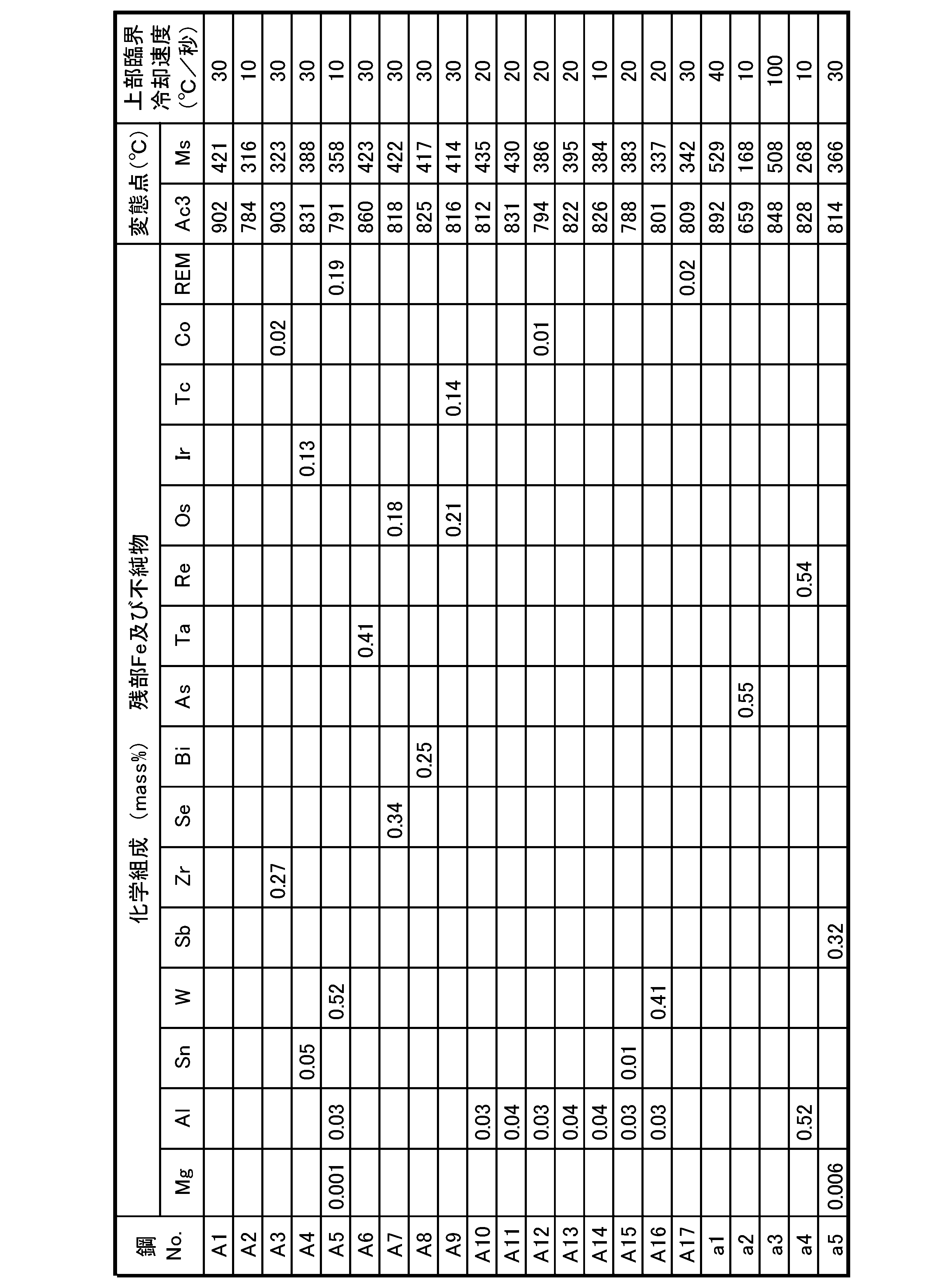
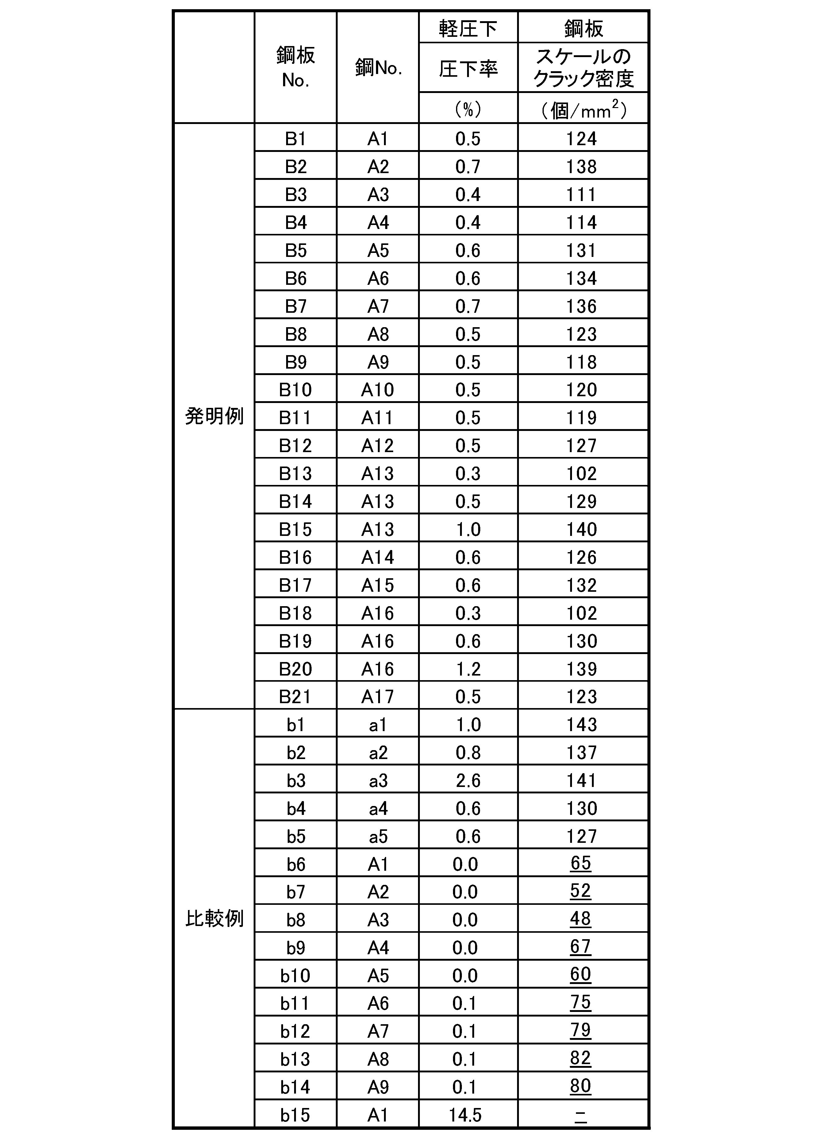
また、鋼板の1/4深さ位置の化学組成を測定した結果、スラブの化学組成と同様であった。
また、熱延板焼鈍後の鋼板のうち、一部の鋼板(C2~C30、c2~c16)に対し、酸洗、冷延を施し、厚さ1.6mmの冷延鋼板を得た。さらに、冷延鋼板のうちの一部(C4~C22、C24~C30、c5~c16)に対し、溶融Alめっきあるいは溶融Znめっきを施した。
熱延板焼鈍後の熱延鋼板、または酸洗、冷間圧延、焼鈍を行った冷延鋼板、または、酸洗、冷間圧延、焼鈍を行い焼鈍の途中(保持後の冷却過程)でめっきを行った冷延鋼板に対し、表3Aに示す条件で熱処理を施し、鋼部材を得た。めっき鋼板に熱処理を行った鋼部材では、表面に、FeとAlとを合計で70質量%以上含むFe-Al系合金層、または、FeとZnとを合計で70質量%以上含むFe-Zn系合金層が、5~100μmの厚みで形成されていた。
鋼部材の幅方向端部から幅(短手)の1/4の位置から断面観察用サンプルを採取し、JISZ2244-1:2020に準じて、1/4深さ位置および0.1mm深さ位置のそれぞれにおいて、ビッカース硬さ測定を行った。試験力は100gfとした。各深さにおいて5回測定を行い、その平均値をその位置の硬さとした。
引張試験はASTM規格E8の規定に準拠して実施した。鋼部材の均熱部位を1.2mm厚まで研削した後、試験方向が圧延方向に平行になるように、ASTM規格E8のハーフサイズ板状試験片(平行部長さ:32mm、平行部板幅:6.25mm)を採取した。そして、試験片平行部の幅および長さ方向中心にひずみゲージ(ゲージ長:5mm、例えば株式会社東京測器研究所製FLAB-5)を貼付け、3mm/minのひずみ速度で室温引張試験を行い、引張強さ(最大強度)を測定した。
本実施例においては、1000MPa以上の引張強さを有する場合を高強度であると評価した。
鋼部材の均熱部位より、圧延方向に平行に60mm、垂直に30mmの曲げ用試験片を採取し、この試験片に対し、DA238―100の規定に準拠して曲げ試験を実施した。
試験に際しては、曲げパンチを圧延方向と垂直となるように合わせ、最大荷重時の曲げ角度を測定した。
曲げ角度は強度と相関があるため、本実施例においては、引張強さに応じてそれぞれ、引張強さが1500MPa未満では70度、引張強さが1500MPa以上2100MPa未満では55度、2100MPa以上では45度、を超える曲げ角度を有する場合を、従来技術より曲げ性に優れると評価した。
耐水素脆性は、試験片に対し4点曲げ試験を行い、割れが発生しない限界まで試験片中に吸蔵可能な水素量Hcにより評価した。具体的には、試験片として、評価対象の鋼部材の端部を避けて、幅8mm、長さ68mmの短冊状の試験片を切り出した。そして、試験片の表面の幅方向および長さ方向の中心に引張試験と同様のひずみゲージ(ゲージ長:5mm、例えば株式会社東京測器研究所製FLAB-5)を貼付けた後、評価対象の鋼部材に対する上述の引張試験により測定された引張強さの3/5相当のひずみまで、4点支持の治具で試験片の長手方向に沿って曲げた。治具としては、内ピン(内側の2つ加力点)の間隔が10mm、外ピン(外側の2つ支点)の間隔が60mmのものを用いた。
吸蔵させた水素量(水素吸蔵量)が異なる複数の試験片について、割れ発生の有無を観察し、割れが発生しない最大(限界)の水素量Hc(mass ppm)を求めた。Fe-Al系被覆を有する鋼部材の場合は、熱処理工程における炉内露点を変更することにより水素吸蔵量を変化させ、4点曲げ試験から72時間以内に割れが発生したか否かを観察した。また、被覆なしの鋼部材、又はFe-Zn系被覆を有する鋼部材の場合は、複数の試験片について、4点曲げ試験後に、それぞれ濃度が異なるチオシアン酸アンモニウム液に浸漬させて水素を吸蔵させ、浸漬後72時間以内に割れが発生したか否かを観察した。鋼部材に吸蔵された水素は、昇温水素分析にて100℃/hrで昇温し250℃までに放出される拡散性水素量を鋼部材に含まれる水素量とした。
本実施例においては、水素量Hcが、引張強さ1500~2000MPa未満の鋼部材については0.7mass ppm以上、引張強さ2000~2500MPa未満の鋼部材については0.5mass ppm以上、引張強さ2500MPa以上の鋼部材については0.3mass ppm以上である場合に、耐水素脆性に優れると評価した。
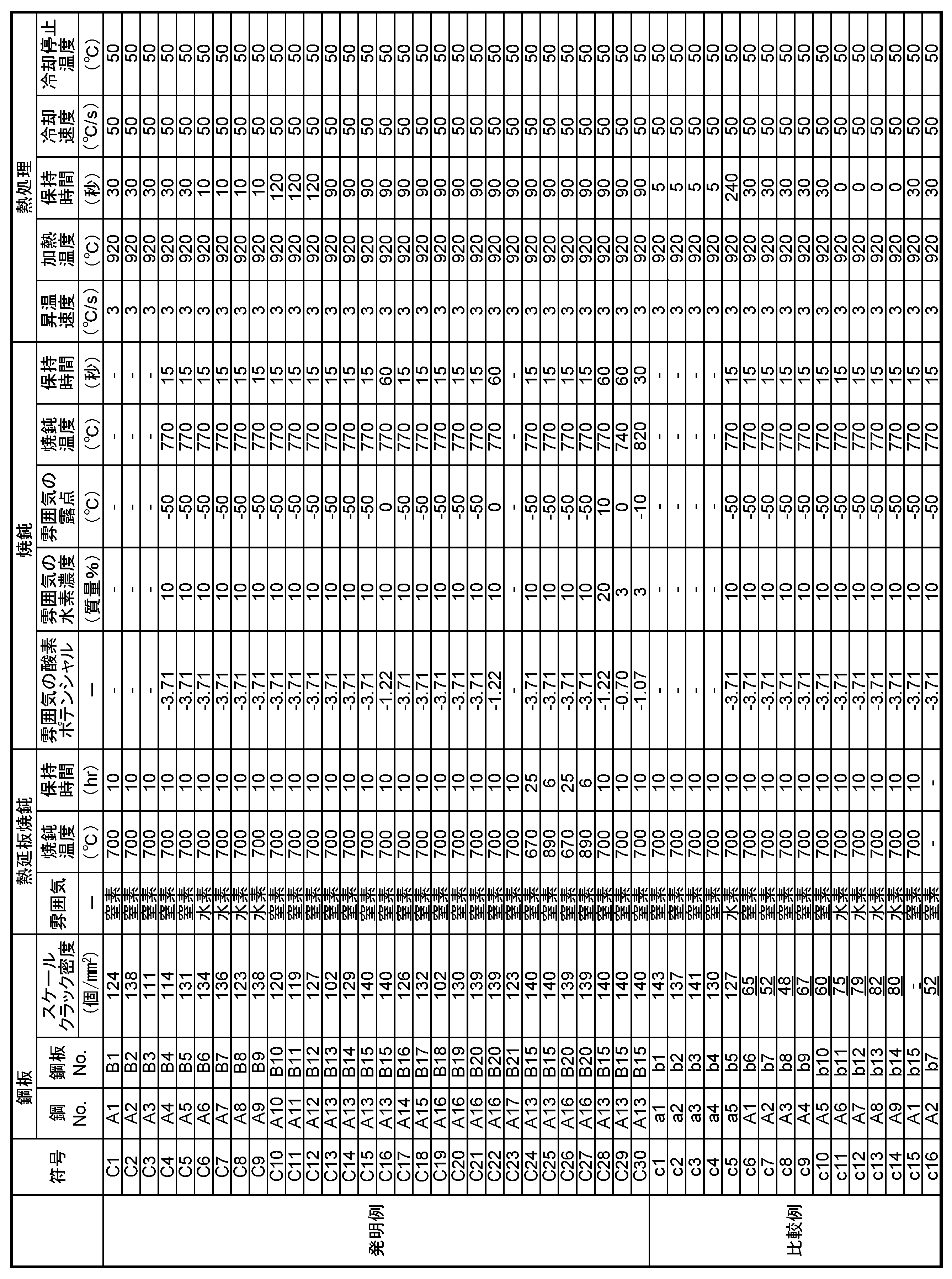

Claims (10)
- 質量%で、
C:0.10~0.70%、
Si:3.00%以下、
Mn:0.01~3.00%、
P:0.100%以下、
S:0.0100%以下、
N:0.020%以下、
O:0.010%以下、
B:0.0002~0.0200%、
Ti:0~0.200%、
Cr:0~1.00%、
Mo:0~1.00%、
Ni:0~2.00%、
Nb:0~0.10%、
Cu:0~2.00%、
V:0~1.00%、
Ca:0~0.020%、
Mg:0~0.020%、
Al:0~1.00%、
Sn:0~1.00%、
W:0~2.00%、
Sb:0~1.00%、
Zr:0~1.00%、
Se:0~1.00%、
Bi:0~1.00%、
As:0~1.00%、
Ta:0~1.00%、
Re:0~1.00%、
Os:0~1.00%、
Ir:0~1.00%、
Tc:0~1.00%、
Co:0~1.00%、
REM:0~0.30%、及び
残部:Fe及び不純物
からなる化学組成を有し、
表面から厚さ方向に厚さの1/4の深さの位置を1/4深さ位置としたとき、
前記表面から前記厚さ方向に10μmの深さまでの範囲における最大B含有量が、前記1/4深さ位置におけるB含有量の5倍以上であり、
前記表面から前記厚さ方向にGDSを用いてC含有量を測定し、前記表面から、最初にC含有量が前記1/4深さ位置のC含有量となる位置までの距離を、脱炭深さとしたとき、前記脱炭深さが20μm以上であり、
前記1/4深さ位置のビッカース硬さが310~890である、
ことを特徴とする鋼部材。 - 前記表面から前記厚さ方向に0.1mmの深さの位置を0.1mm深さ位置としたとき、前記0.1mm深さ位置のビッカース硬さが前記1/4深さ位置の前記ビッカース硬さの0.95倍以下である、
ことを特徴とする、請求項1に記載の鋼部材。 - 前記1/4深さ位置の前記ビッカース硬さが、310~450であり、
板厚1.6mmの鋼部材を曲げ角50度まで変形させたとき、曲げ外表層中心の最大主塑性ひずみが0.340以下である、
ことを特徴とする請求項2に記載の鋼部材。 - 前記1/4深さ位置の前記ビッカース硬さが、450超、530以下であり、前記0.1mm深さ位置のビッカース硬さが前記1/4深さ位置の前記ビッカース硬さの0.90倍以下であり、
板厚1.6mmの鋼部材を曲げ角50度まで変形させたとき、曲げ外表層中心の最大主塑性ひずみが0.310以下である、
ことを特徴とする請求項2に記載の鋼部材。 - 前記1/4深さ位置の前記ビッカース硬さが、530超、700以下であり、前記0.1mm深さ位置のビッカース硬さが前記1/4深さ位置の前記ビッカース硬さの0.88倍以下であり、
板厚1.6mmの鋼部材を曲げ角50度まで変形させたとき、曲げ外表層中心の最大主塑性ひずみが0.280以下である、
ことを特徴とする、請求項2に記載の鋼部材。 - 前記1/4深さ位置の前記ビッカース硬さが、700超、890以下であり、前記0.1mm深さ位置のビッカース硬さが前記1/4深さ位置の前記ビッカース硬さの0.86倍以下であり、
板厚1.6mmの鋼部材を曲げ角50度まで変形させたとき、曲げ外表層中心の最大主塑性ひずみが0.260以下である、
ことを特徴とする、請求項2に記載の鋼部材。 - さらに、前記表面に合金層を有する、
ことを特徴とする請求項1~6のいずれか一項に記載の鋼部材。 - 前記合金層が、Fe-Al系合金層である、
ことを特徴とする請求項7に記載の鋼部材。 - 前記合金層が、Fe-Zn系合金層である、
ことを特徴とする請求項7に記載の鋼部材。 - 母材鋼板と、
前記母材鋼板の表面に形成された鉄スケールと、
を有し、
前記母材鋼板が、質量%で、
C:0.10~0.70%、
Si:3.00%以下、
Mn:0.01~3.00%、
P:0.100%以下、
S:0.0100%以下、
N:0.020%以下、
O:0.010%以下、
B:0.0002~0.0200%、
Ti:0~0.200%、
Cr:0~1.00%、
Mo:0~1.00%、
Ni:0~2.00%、
Nb:0~0.10%、
Cu:0~2.00%、
V:0~1.00%、
Ca:0~0.020%、
Mg:0~0.020%、
Al:0~1.00%、
Sn:0~1.00%、
W:0~2.00%、
Sb:0~1.00%、
Zr:0~1.00%、
Se:0~1.00%、
Bi:0~1.00%、
As:0~1.00%、
Ta:0~1.00%、
Re:0~1.00%、
Os:0~1.00%、
Ir:0~1.00%、
Tc:0~1.00%、
Co:0~1.00%、
REM:0~0.30%、及び
残部:Fe及び不純物からなる化学組成を有し、
前記鉄スケールが、クラックを90個/mm2以上の密度で含む、
ことを特徴とする鋼板。
Priority Applications (5)
| Application Number | Priority Date | Filing Date | Title |
|---|---|---|---|
| KR1020247031722A KR20240155913A (ko) | 2022-03-30 | 2023-03-30 | 강 부재 및 강판 |
| MX2024011522A MX2024011522A (es) | 2022-03-30 | 2023-03-30 | Miembro de acero y lamina de acero. |
| EP23780875.3A EP4502193A4 (en) | 2022-03-30 | 2023-03-30 | STEEL ELEMENT AND STEEL SHEET |
| JP2024512794A JPWO2023190867A1 (ja) | 2022-03-30 | 2023-03-30 | |
| CN202380029343.8A CN118922573A (zh) | 2022-03-30 | 2023-03-30 | 钢构件及钢板 |
Applications Claiming Priority (2)
| Application Number | Priority Date | Filing Date | Title |
|---|---|---|---|
| JP2022-055819 | 2022-03-30 | ||
| JP2022055819 | 2022-03-30 |
Publications (1)
| Publication Number | Publication Date |
|---|---|
| WO2023190867A1 true WO2023190867A1 (ja) | 2023-10-05 |
Family
ID=88202887
Family Applications (1)
| Application Number | Title | Priority Date | Filing Date |
|---|---|---|---|
| PCT/JP2023/013175 Ceased WO2023190867A1 (ja) | 2022-03-30 | 2023-03-30 | 鋼部材及び鋼板 |
Country Status (6)
| Country | Link |
|---|---|
| EP (1) | EP4502193A4 (ja) |
| JP (1) | JPWO2023190867A1 (ja) |
| KR (1) | KR20240155913A (ja) |
| CN (1) | CN118922573A (ja) |
| MX (1) | MX2024011522A (ja) |
| WO (1) | WO2023190867A1 (ja) |
Cited By (4)
| Publication number | Priority date | Publication date | Assignee | Title |
|---|---|---|---|---|
| WO2025198021A1 (ja) * | 2024-03-21 | 2025-09-25 | 日本製鉄株式会社 | ホットスタンプ用鋼板及びホットスタンプ成形体 |
| WO2025249571A1 (ja) * | 2024-05-30 | 2025-12-04 | 日本製鉄株式会社 | 鋼部材及び鋼板 |
| WO2025254096A1 (ja) * | 2024-06-04 | 2025-12-11 | 日本製鉄株式会社 | 鋼板及びそれを含む部品 |
| WO2025263129A1 (ja) * | 2024-06-21 | 2025-12-26 | 日本製鉄株式会社 | ホットスタンプ成形体 |
Citations (17)
| Publication number | Priority date | Publication date | Assignee | Title |
|---|---|---|---|---|
| JP2002102980A (ja) | 2000-07-28 | 2002-04-09 | Aisin Takaoka Ltd | 車輌用衝突補強材の製造方法および車輌用衝突補強材 |
| JP2004346416A (ja) * | 2003-05-26 | 2004-12-09 | Kobe Steel Ltd | スケール密着性に優れた熱延鋼板 |
| JP2006161064A (ja) * | 2004-12-02 | 2006-06-22 | Sumitomo Metal Ind Ltd | 高張力溶融亜鉛めっき鋼板とその製造方法 |
| JP2011202231A (ja) * | 2010-03-25 | 2011-10-13 | Nisshin Steel Co Ltd | 酸洗性および加工性に優れた熱延鋼板の製造方法 |
| JP2011236483A (ja) * | 2010-05-12 | 2011-11-24 | Sumitomo Metal Ind Ltd | 熱処理用鋼板およびその製造方法 |
| JP2012001802A (ja) | 2010-06-21 | 2012-01-05 | Sumitomo Metal Ind Ltd | 鋼材およびその製造方法ならびに焼入処理用鋼板 |
| JP2012514133A (ja) * | 2008-12-26 | 2012-06-21 | ポスコ | 表面脱炭が抑制された鋼材及びその製造方法 |
| JP2012180594A (ja) | 2006-05-10 | 2012-09-20 | Sumitomo Metal Ind Ltd | 熱間プレス成形された鋼板部材および熱間プレス鋼板部材用鋼板ならびにそれらの製造方法 |
| JP2013237101A (ja) * | 2012-04-20 | 2013-11-28 | Kobe Steel Ltd | 耐水素誘起割れ性に優れた鋼材およびその製造方法 |
| JP2014136824A (ja) * | 2013-01-17 | 2014-07-28 | Nisshin Steel Co Ltd | 素材スラブ、薄鋼板及びその製造方法 |
| WO2015182596A1 (ja) | 2014-05-29 | 2015-12-03 | 新日鐵住金株式会社 | 熱処理鋼材及びその製造方法 |
| WO2015182591A1 (ja) | 2014-05-29 | 2015-12-03 | 新日鐵住金株式会社 | 熱処理鋼材及びその製造方法 |
| WO2021019947A1 (ja) * | 2019-07-30 | 2021-02-04 | Jfeスチール株式会社 | 高強度鋼板およびその製造方法 |
| WO2021117989A1 (ko) * | 2019-12-09 | 2021-06-17 | 현대제철 주식회사 | 초고강도 냉연강판 및 이의 제조방법 |
| JP2021155790A (ja) * | 2020-03-26 | 2021-10-07 | 日本製鉄株式会社 | ホットスタンプ部品およびその製造方法 |
| WO2021255858A1 (ja) * | 2020-06-17 | 2021-12-23 | 日本製鉄株式会社 | 鋼板 |
| JP2022055819A (ja) | 2020-09-29 | 2022-04-08 | コベルコ建機株式会社 | 抜け止めユニット |
Family Cites Families (6)
| Publication number | Priority date | Publication date | Assignee | Title |
|---|---|---|---|---|
| JP5273324B1 (ja) * | 2011-07-29 | 2013-08-28 | 新日鐵住金株式会社 | 曲げ性に優れた高強度亜鉛めっき鋼板およびその製造方法 |
| UA116699C2 (uk) * | 2013-12-11 | 2018-04-25 | Арселорміттал | Лист з мартенситної сталі і спосіб його отримання, а також деталь і конструктивний елемент транспортного засобу, виконані з вказаного листа, і сам транспортний засіб |
| JP6010144B2 (ja) * | 2015-01-09 | 2016-10-19 | 株式会社神戸製鋼所 | めっき性、加工性、および耐遅れ破壊特性に優れた高強度めっき鋼板、並びにその製造方法 |
| WO2016163467A1 (ja) * | 2015-04-08 | 2016-10-13 | 新日鐵住金株式会社 | 熱処理用鋼板 |
| EP3584339B1 (en) * | 2017-02-20 | 2022-01-19 | Nippon Steel Corporation | Steel sheet |
| CN113597474B (zh) * | 2019-03-20 | 2023-04-28 | 日本制铁株式会社 | 热冲压成形体 |
-
2023
- 2023-03-30 JP JP2024512794A patent/JPWO2023190867A1/ja active Pending
- 2023-03-30 WO PCT/JP2023/013175 patent/WO2023190867A1/ja not_active Ceased
- 2023-03-30 KR KR1020247031722A patent/KR20240155913A/ko active Pending
- 2023-03-30 MX MX2024011522A patent/MX2024011522A/es unknown
- 2023-03-30 CN CN202380029343.8A patent/CN118922573A/zh active Pending
- 2023-03-30 EP EP23780875.3A patent/EP4502193A4/en active Pending
Patent Citations (17)
| Publication number | Priority date | Publication date | Assignee | Title |
|---|---|---|---|---|
| JP2002102980A (ja) | 2000-07-28 | 2002-04-09 | Aisin Takaoka Ltd | 車輌用衝突補強材の製造方法および車輌用衝突補強材 |
| JP2004346416A (ja) * | 2003-05-26 | 2004-12-09 | Kobe Steel Ltd | スケール密着性に優れた熱延鋼板 |
| JP2006161064A (ja) * | 2004-12-02 | 2006-06-22 | Sumitomo Metal Ind Ltd | 高張力溶融亜鉛めっき鋼板とその製造方法 |
| JP2012180594A (ja) | 2006-05-10 | 2012-09-20 | Sumitomo Metal Ind Ltd | 熱間プレス成形された鋼板部材および熱間プレス鋼板部材用鋼板ならびにそれらの製造方法 |
| JP2012514133A (ja) * | 2008-12-26 | 2012-06-21 | ポスコ | 表面脱炭が抑制された鋼材及びその製造方法 |
| JP2011202231A (ja) * | 2010-03-25 | 2011-10-13 | Nisshin Steel Co Ltd | 酸洗性および加工性に優れた熱延鋼板の製造方法 |
| JP2011236483A (ja) * | 2010-05-12 | 2011-11-24 | Sumitomo Metal Ind Ltd | 熱処理用鋼板およびその製造方法 |
| JP2012001802A (ja) | 2010-06-21 | 2012-01-05 | Sumitomo Metal Ind Ltd | 鋼材およびその製造方法ならびに焼入処理用鋼板 |
| JP2013237101A (ja) * | 2012-04-20 | 2013-11-28 | Kobe Steel Ltd | 耐水素誘起割れ性に優れた鋼材およびその製造方法 |
| JP2014136824A (ja) * | 2013-01-17 | 2014-07-28 | Nisshin Steel Co Ltd | 素材スラブ、薄鋼板及びその製造方法 |
| WO2015182596A1 (ja) | 2014-05-29 | 2015-12-03 | 新日鐵住金株式会社 | 熱処理鋼材及びその製造方法 |
| WO2015182591A1 (ja) | 2014-05-29 | 2015-12-03 | 新日鐵住金株式会社 | 熱処理鋼材及びその製造方法 |
| WO2021019947A1 (ja) * | 2019-07-30 | 2021-02-04 | Jfeスチール株式会社 | 高強度鋼板およびその製造方法 |
| WO2021117989A1 (ko) * | 2019-12-09 | 2021-06-17 | 현대제철 주식회사 | 초고강도 냉연강판 및 이의 제조방법 |
| JP2021155790A (ja) * | 2020-03-26 | 2021-10-07 | 日本製鉄株式会社 | ホットスタンプ部品およびその製造方法 |
| WO2021255858A1 (ja) * | 2020-06-17 | 2021-12-23 | 日本製鉄株式会社 | 鋼板 |
| JP2022055819A (ja) | 2020-09-29 | 2022-04-08 | コベルコ建機株式会社 | 抜け止めユニット |
Non-Patent Citations (1)
| Title |
|---|
| See also references of EP4502193A4 |
Cited By (5)
| Publication number | Priority date | Publication date | Assignee | Title |
|---|---|---|---|---|
| WO2025198021A1 (ja) * | 2024-03-21 | 2025-09-25 | 日本製鉄株式会社 | ホットスタンプ用鋼板及びホットスタンプ成形体 |
| WO2025249571A1 (ja) * | 2024-05-30 | 2025-12-04 | 日本製鉄株式会社 | 鋼部材及び鋼板 |
| WO2025254096A1 (ja) * | 2024-06-04 | 2025-12-11 | 日本製鉄株式会社 | 鋼板及びそれを含む部品 |
| JP7817659B1 (ja) * | 2024-06-04 | 2026-02-19 | 日本製鉄株式会社 | 鋼板及びそれを含む部品 |
| WO2025263129A1 (ja) * | 2024-06-21 | 2025-12-26 | 日本製鉄株式会社 | ホットスタンプ成形体 |
Also Published As
| Publication number | Publication date |
|---|---|
| EP4502193A1 (en) | 2025-02-05 |
| KR20240155913A (ko) | 2024-10-29 |
| JPWO2023190867A1 (ja) | 2023-10-05 |
| CN118922573A (zh) | 2024-11-08 |
| MX2024011522A (es) | 2024-09-25 |
| EP4502193A4 (en) | 2025-07-30 |
Similar Documents
| Publication | Publication Date | Title |
|---|---|---|
| JP7111252B2 (ja) | 被覆鋼部材、被覆鋼板およびそれらの製造方法 | |
| CN113840934B (zh) | 高强度构件、高强度构件的制造方法和高强度构件用钢板的制造方法 | |
| JP7747986B2 (ja) | 鋼板および鋼板の製造方法 | |
| WO2023190867A1 (ja) | 鋼部材及び鋼板 | |
| JP7216933B2 (ja) | 鋼板およびその製造方法 | |
| CN114729429A (zh) | 被覆钢构件、被覆钢板及它们的制造方法 | |
| JP7553837B2 (ja) | ホットスタンプ用鋼板及びその製造方法、並びに、ホットスタンプ部材及びその製造方法 | |
| JP7791453B2 (ja) | 鋼部材及び鋼板 | |
| JP7695582B2 (ja) | 鋼板、鋼部材及び被覆鋼部材 | |
| WO2024166891A1 (ja) | ホットスタンプ成形体及び鋼板、並びにこれらの製造方法 | |
| WO2023162190A1 (ja) | 鋼板、部材、それらの製造方法、冷延鋼板用熱延鋼板の製造方法及び冷延鋼板の製造方法 | |
| JP7617452B2 (ja) | 鋼材 | |
| WO2023199776A1 (ja) | ホットスタンプ成形体 | |
| JP7708344B1 (ja) | 亜鉛めっき鋼板および部材、ならびに、それらの製造方法 | |
| EP4640883A1 (en) | Cold-rolled steel sheet and manufacturing method therefor | |
| WO2025249571A1 (ja) | 鋼部材及び鋼板 | |
| WO2024190779A1 (ja) | 鋼部材及び鋼板 | |
| WO2025249572A1 (ja) | 鋼部材及び鋼板 | |
| WO2025249559A1 (ja) | 鋼部材及び鋼板 | |
| WO2025263571A1 (ja) | 鋼部材及び鋼板 | |
| KR20250143340A (ko) | 강 부재 및 강판 | |
| WO2023162381A1 (ja) | 鋼板、部材、それらの製造方法、冷延鋼板用熱延鋼板の製造方法及び冷延鋼板の製造方法 | |
| WO2025263572A1 (ja) | 鋼部材及び鋼板 | |
| WO2024190415A1 (ja) | 鋼板 | |
| WO2024122119A1 (ja) | ホットスタンプ成形体 |
Legal Events
| Date | Code | Title | Description |
|---|---|---|---|
| 121 | Ep: the epo has been informed by wipo that ep was designated in this application |
Ref document number: 23780875 Country of ref document: EP Kind code of ref document: A1 |
|
| ENP | Entry into the national phase |
Ref document number: 2024512794 Country of ref document: JP Kind code of ref document: A |
|
| WWE | Wipo information: entry into national phase |
Ref document number: 18845720 Country of ref document: US |
|
| WWE | Wipo information: entry into national phase |
Ref document number: 202417070639 Country of ref document: IN |
|
| WWE | Wipo information: entry into national phase |
Ref document number: MX/A/2024/011522 Country of ref document: MX |
|
| ENP | Entry into the national phase |
Ref document number: 20247031722 Country of ref document: KR Kind code of ref document: A |
|
| WWE | Wipo information: entry into national phase |
Ref document number: 202380029343.8 Country of ref document: CN Ref document number: 1020247031722 Country of ref document: KR |
|
| WWE | Wipo information: entry into national phase |
Ref document number: 2401006288 Country of ref document: TH |
|
| WWE | Wipo information: entry into national phase |
Ref document number: 2023780875 Country of ref document: EP |
|
| NENP | Non-entry into the national phase |
Ref country code: DE |
|
| ENP | Entry into the national phase |
Ref document number: 2023780875 Country of ref document: EP Effective date: 20241030 |
|
| WWP | Wipo information: published in national office |
Ref document number: 202417070639 Country of ref document: IN |