WO2023195058A1 - 成膜装置 - Google Patents
成膜装置 Download PDFInfo
- Publication number
- WO2023195058A1 WO2023195058A1 PCT/JP2022/017073 JP2022017073W WO2023195058A1 WO 2023195058 A1 WO2023195058 A1 WO 2023195058A1 JP 2022017073 W JP2022017073 W JP 2022017073W WO 2023195058 A1 WO2023195058 A1 WO 2023195058A1
- Authority
- WO
- WIPO (PCT)
- Prior art keywords
- magnetic field
- cathode
- plasma
- field generating
- anode
- Prior art date
- Legal status (The legal status is an assumption and is not a legal conclusion. Google has not performed a legal analysis and makes no representation as to the accuracy of the status listed.)
- Ceased
Links
Images


Classifications
-
- C—CHEMISTRY; METALLURGY
- C23—COATING METALLIC MATERIAL; COATING MATERIAL WITH METALLIC MATERIAL; CHEMICAL SURFACE TREATMENT; DIFFUSION TREATMENT OF METALLIC MATERIAL; COATING BY VACUUM EVAPORATION, BY SPUTTERING, BY ION IMPLANTATION OR BY CHEMICAL VAPOUR DEPOSITION, IN GENERAL; INHIBITING CORROSION OF METALLIC MATERIAL OR INCRUSTATION IN GENERAL
- C23C—COATING METALLIC MATERIAL; COATING MATERIAL WITH METALLIC MATERIAL; SURFACE TREATMENT OF METALLIC MATERIAL BY DIFFUSION INTO THE SURFACE, BY CHEMICAL CONVERSION OR SUBSTITUTION; COATING BY VACUUM EVAPORATION, BY SPUTTERING, BY ION IMPLANTATION OR BY CHEMICAL VAPOUR DEPOSITION, IN GENERAL
- C23C14/00—Coating by vacuum evaporation, by sputtering or by ion implantation of the coating forming material
- C23C14/22—Coating by vacuum evaporation, by sputtering or by ion implantation of the coating forming material characterised by the process of coating
- C23C14/24—Vacuum evaporation
- C23C14/32—Vacuum evaporation by explosion; by evaporation and subsequent ionisation of the vapours, e.g. ion-plating
-
- H—ELECTRICITY
- H01—ELECTRIC ELEMENTS
- H01J—ELECTRIC DISCHARGE TUBES OR DISCHARGE LAMPS
- H01J37/00—Discharge tubes with provision for introducing objects or material to be exposed to the discharge, e.g. for the purpose of examination or processing thereof
- H01J37/32—Gas-filled discharge tubes
- H01J37/32431—Constructional details of the reactor
- H01J37/3266—Magnetic control means
- H01J37/32669—Particular magnets or magnet arrangements for controlling the discharge
-
- C—CHEMISTRY; METALLURGY
- C23—COATING METALLIC MATERIAL; COATING MATERIAL WITH METALLIC MATERIAL; CHEMICAL SURFACE TREATMENT; DIFFUSION TREATMENT OF METALLIC MATERIAL; COATING BY VACUUM EVAPORATION, BY SPUTTERING, BY ION IMPLANTATION OR BY CHEMICAL VAPOUR DEPOSITION, IN GENERAL; INHIBITING CORROSION OF METALLIC MATERIAL OR INCRUSTATION IN GENERAL
- C23C—COATING METALLIC MATERIAL; COATING MATERIAL WITH METALLIC MATERIAL; SURFACE TREATMENT OF METALLIC MATERIAL BY DIFFUSION INTO THE SURFACE, BY CHEMICAL CONVERSION OR SUBSTITUTION; COATING BY VACUUM EVAPORATION, BY SPUTTERING, BY ION IMPLANTATION OR BY CHEMICAL VAPOUR DEPOSITION, IN GENERAL
- C23C14/00—Coating by vacuum evaporation, by sputtering or by ion implantation of the coating forming material
- C23C14/22—Coating by vacuum evaporation, by sputtering or by ion implantation of the coating forming material characterised by the process of coating
- C23C14/24—Vacuum evaporation
- C23C14/32—Vacuum evaporation by explosion; by evaporation and subsequent ionisation of the vapours, e.g. ion-plating
- C23C14/325—Electric arc evaporation
-
- H—ELECTRICITY
- H01—ELECTRIC ELEMENTS
- H01J—ELECTRIC DISCHARGE TUBES OR DISCHARGE LAMPS
- H01J37/00—Discharge tubes with provision for introducing objects or material to be exposed to the discharge, e.g. for the purpose of examination or processing thereof
- H01J37/32—Gas-filled discharge tubes
- H01J37/32009—Arrangements for generation of plasma specially adapted for examination or treatment of objects, e.g. plasma sources
- H01J37/32055—Arc discharge
-
- H—ELECTRICITY
- H01—ELECTRIC ELEMENTS
- H01J—ELECTRIC DISCHARGE TUBES OR DISCHARGE LAMPS
- H01J37/00—Discharge tubes with provision for introducing objects or material to be exposed to the discharge, e.g. for the purpose of examination or processing thereof
- H01J37/32—Gas-filled discharge tubes
- H01J37/32431—Constructional details of the reactor
- H01J37/32532—Electrodes
- H01J37/32559—Protection means, e.g. coatings
-
- H—ELECTRICITY
- H01—ELECTRIC ELEMENTS
- H01J—ELECTRIC DISCHARGE TUBES OR DISCHARGE LAMPS
- H01J37/00—Discharge tubes with provision for introducing objects or material to be exposed to the discharge, e.g. for the purpose of examination or processing thereof
- H01J37/32—Gas-filled discharge tubes
- H01J37/32431—Constructional details of the reactor
- H01J37/3266—Magnetic control means
-
- H—ELECTRICITY
- H05—ELECTRIC TECHNIQUES NOT OTHERWISE PROVIDED FOR
- H05H—PLASMA TECHNIQUE; PRODUCTION OF ACCELERATED ELECTRICALLY-CHARGED PARTICLES OR OF NEUTRONS; PRODUCTION OR ACCELERATION OF NEUTRAL MOLECULAR OR ATOMIC BEAMS
- H05H1/00—Generating plasma; Handling plasma
- H05H1/24—Generating plasma
- H05H1/26—Plasma torches
- H05H1/32—Plasma torches using an arc
- H05H1/34—Details, e.g. electrodes, nozzles
- H05H1/40—Details, e.g. electrodes, nozzles using applied magnetic fields, e.g. for focusing or rotating the arc
-
- H—ELECTRICITY
- H01—ELECTRIC ELEMENTS
- H01J—ELECTRIC DISCHARGE TUBES OR DISCHARGE LAMPS
- H01J2237/00—Discharge tubes exposing object to beam, e.g. for analysis treatment, etching, imaging
- H01J2237/32—Processing objects by plasma generation
- H01J2237/33—Processing objects by plasma generation characterised by the type of processing
- H01J2237/332—Coating
- H01J2237/3322—Problems associated with coating
- H01J2237/3323—Problems associated with coating uniformity
-
- H—ELECTRICITY
- H05—ELECTRIC TECHNIQUES NOT OTHERWISE PROVIDED FOR
- H05H—PLASMA TECHNIQUE; PRODUCTION OF ACCELERATED ELECTRICALLY-CHARGED PARTICLES OR OF NEUTRONS; PRODUCTION OR ACCELERATION OF NEUTRAL MOLECULAR OR ATOMIC BEAMS
- H05H2242/00—Auxiliary systems
- H05H2242/10—Cooling arrangements
Definitions
- the present invention relates to a film forming apparatus, and particularly to an apparatus that generates plasma by arc discharge in a vacuum (for example, 0.0001 to 50 Pa) and evaporates a cathode material to form a film on the surface of a workpiece.
- a vacuum for example, 0.0001 to 50 Pa
- a solid material can be improved by generating plasma to form a thin film on the surface of the solid material (workpiece) or by implanting ions. ing. Films formed using plasma containing metal ions and/or non-metal ions enhance the wear resistance and corrosion resistance of solid surfaces and are useful as protective films and the like.
- a carbon film using carbon plasma has high utility value as a diamond-like carbon film (DLC film) consisting of an amorphous hybrid of a diamond structure and a graphite structure.
- DLC film diamond-like carbon film
- metal nitride films such as titanium nitride films and titanium aluminum nitride films, which are formed by introducing nitrogen gas into the atmosphere and evaporating metals or alloys such as titanium (Ti) and titanium aluminum (TiAl), are It is also known that it can be used in various ways, such as as a protective film for parts and parts, and as a decoration for other parts. Such methods are called vacuum arc deposition, arc ion plating, arc PVD, cathodic arc deposition, and the like. In most general vacuum arc evaporation apparatuses, the vacuum vessel itself functions as an anode, but the present invention relates to an apparatus in which the anode is placed inside the vacuum vessel, independent of the vacuum vessel.
- Vacuum arc discharge is generated between a cathode and an anode, exists on the surface of the cathode, and is generated at the starting point of vacuum arc discharge.
- Cathode material evaporates from a hot cathode spot, and a vacuum arc plasma is formed by the cathode evaporated material.
- reactive gases nitrogen, oxygen, hydrogen, hydrocarbons, fluorine, silicon, etc.
- inert gases rare gases
- constituent particles such as electrons and cathode material evaporated particles (atoms (or molecules)) are emitted from the cathode spot, and particles ranging from submicrons to hundreds of microns (0.01 to Droplets (also called macroparticles) with a size of 1000 ⁇ m are also released as by-product particles at the same time.
- electrons emitted from the cathode spot collide with the evaporated particles of the cathode material, thereby ionizing the particles and generating metal ions and/or non-metal ions.
- Cathode material evaporated particles are exclusively ionized by colliding with electrons immediately after being emitted from the cathode spot (at a very close distance of several mm from the cathode surface), but cathode material evaporation particles that are not ionized (excluding those that are subsequently ionized) ), introduced gas particles (molecules or atoms), reaction particles (molecules), etc., become neutral particles (hereinafter sometimes referred to collectively as neutral particles), and are initially treated as particles that are not affected by magnetic and electric fields. It will go straight in the direction of emission.
- droplets are bumped and ejected at the cathode section, but since they also have no electric charge, they proceed without being affected by magnetic and electric fields.
- droplets by-product fine particles adhere to the surface of the substrate. That is, when droplets (by-product particles) adhere to the surface of a solid material, the surface becomes uneven and the uniformity of the thin film is not maintained, resulting in a low-quality or defective product.
- some of the inventors of the present application have proposed that the flow of plasma emitted from the plasma generation section (vacuum arc plasma generated at the cathode point be transferred to the anode and/or
- the flow of plasma toward an object (hereinafter sometimes referred to as plasma flow) is bent by a curved magnetic field, guiding the plasma flow in a direction that does not face the plasma generation part, while directing by-product particles in a direction facing the plasma generation part.
- a plasma generator configured to separate a plasma flow and droplets (by-product particles) by guiding the plasma flow to the droplets (see Patent Document 1).
- a substantially T-shaped branch structure was used so that the droplets (by-product particles) were allowed to advance straight and the plasma flow was bent in the lateral direction. Therefore, the branching separates the droplets (by-product particles) from the plasma flow, allowing only the plasma flow to reach the solid material.
- droplets (by-product particulates) emitted from the plasma generation part may collide with the side wall of the plasma path along which the plasma advances, and the droplets (by-product particulates) are reflected by the collision, causing the plasma flow to Sometimes it got mixed in.
- the droplets (by-product particles) mixed into the plasma flow in this way adhere to the surface of the solid material and impede the smoothness of the surface.
- a restriction plate that restricts the advancement of droplets (by-product particles) inside the plasma traveling path, and an oblique movement that reflects the droplets (by-product particles) that have passed through the restriction plate.
- a configuration having a wall see Patent Document 2.
- the traveling direction of droplets (by-product fine particles) is restricted by a restriction plate provided near the plasma generation part, and the droplets (by-product fine particles) travel in a predetermined direction after passing through the restriction plate.
- the droplets (by-product fine particles) are further reflected by a diagonal wall and collected by a collection section placed at a desired position.
- the distance from the plasma generation part (cathode part) to the solid material (workpiece) needs to be 500 mm or more, which is approximately 500 mm to 1,000 mm. Generally, it was set within the range of . The reason for this is that in order to bend the plasma flow, it is necessary to arrange a plurality of magnetic field generators while ensuring a space for the plasma flow to flow, resulting in a longer flow path.
- the flow path that also serves as a magnetic field generation coil is S-shaped (see Non-Patent Document 1), but even in this case, the actual flow path length of the plasma flow is long as a result. .
- droplets (by-products) separated from the plasma flow are used.
- the particles fine particles
- the magnetic generation coil is curved to make the flow path S-shaped, the magnetic generation coil A gap is created in the curved part, and the droplets (by-product particles) can adhere to the solid material (processed object) as they progress toward the solid material (processed object) located at the opposite position through the gap. It became.
- the present invention has been made in view of the above points, and its purpose is to reduce the adhesion of by-product fine particles to the surface of the workpiece, and to reduce the adhesion of particles released from the cathode (atmosphere introduction gas). It is an object of the present invention to provide a film forming apparatus that can reduce the adhesion of magnetic field generating parts (including those that have reacted) to the magnetic field generating part itself, and can effectively form a film by vapor deposition.
- a first configuration of the present invention is provided with a plasma generating means for generating plasma by performing arc discharge between a cathode and an anode connected via a power source in vacuum, and a cathode material constituting the cathode.
- the plasma generating means includes a cathode section, an anode section disposed at an appropriate distance from the cathode section, and an anode section.
- a magnetic field generating section that is configured integrally or continuously with the anode section and generates a magnetic field by the self-current of the arc discharge itself;
- the magnetic field generating section may be configured independently while being connected to the magnetic field generating section, or may be substituted by a part of the magnetic field generating section, and placed between the magnetic field generating section and the plasma, so that part or all of the magnetic field generating section is connected to the cathode material.
- the invention is characterized by comprising a protection member that protects from
- the magnetic field generating section is configured to generate a magnetic field by using the current generated by arc discharge by the anode section (the anode section or a member configured integrally or continuously with the anode section) constituting the plasma generation means. Therefore, it is possible to generate a magnetic field for inducing a plasma flow at a position extremely close to the plasma generating means.
- a protective member is provided outside the plasma flow induced by the magnetic field generating section, and by placing this protective member between the cathode section and the magnetic field generating section, particles emitted from the cathode ( (hereinafter sometimes referred to as released substances). Protection means protecting the magnetic field generating part from adhesion of emitted substances.
- the emitted substances include uncharged neutral particles (evaporated substances) and droplets (by-product particles).
- Some of the neutral particles that are evaporated substances become ions by collision with electrons.
- Charged particles such as electrons and ions are guided by the magnetic field of the magnetic field generating section and guided toward the object to be processed, but neutral particles and droplets are not affected by the magnetic field and travel straight in the direction in which they are radially released. Therefore, when the droplets are attached due to the selection of the cathode material, the magnetic field generating section can be protected by attaching the droplets to the protection member together with the neutral particles.
- ions that cannot be fully controlled by the magnetic field also adhere, but this explanation will be omitted hereafter.
- the magnetic field generating part can be protected by colliding the droplets with the protective member, and the neutral particles can be prevented by adhering.
- the magnetic field generating section can be protected.
- the magnetic field generating section will not be adversely affected by the droplets even if the degree of protection is insufficient.
- the purpose of bouncing (reflecting) the colliding droplets by the protection member is to prevent them from advancing toward the object to be processed.
- the reflective surface of the protection member so that the traveling direction after reflection is not directed toward the object to be processed, it is possible to reduce the amount of droplets reaching the object to be processed.
- the droplets that advance to the object to be treated from the time they are released from the cathode may adhere to the surface of the object to be treated, but if we accept the amount of adhesion, no preventive measures can be taken.
- the amount of droplets attached will be reduced compared to the case where no measures are taken.
- it contributes to effective vapor deposition formation of a film.
- the magnetic field generating section is formed in a substantially cylindrical shape around a region in which the plasma flow flows, and the protection member is formed in a substantially cylindrical shape.
- the magnetic field generating section is disposed at at least one edge located on the cathode side or the opposite side thereof, and has a surface having an appropriate area in the radial direction of the magnetic field generating section, and introduces cooling water into the inside thereof. It is constituted by a water cooling ring member having a hollow part for cooling.
- the magnetic field generating section is approximately cylindrical, and the plasma flow is induced to flow inside the magnetic field generating section.
- one edge should have a ring shape (it does not have to be a complete ring, as it is partially cut off.
- the magnetic field generating part it is possible to protect the magnetic field generating part by reflecting the droplets while adhering the droplets. Basically, by placing a protective member on the edge of the cathode side, evaporated particles (neutral particles evaporated from the cathode and subsequently ionized particles) and droplets are attached (or reflection). In addition, by providing a protective member on the opposite edge of the above, the droplets traveling toward the object to be processed are attached (or reflected), thereby reducing the amount of droplets reaching the object to be processed. I can do it.
- the protective member functions as a part of the anode by being electrically connected to the anode, and functions as a part of the plasma generating means.
- substantially cylindrical refers to an electromagnetic coil wired in a coil shape, but in addition to a coil shape that is formed continuously in the circumferential direction, it can also be used to electrically connect members that are not continuous in the circumferential direction. It means a concept that also includes the structure.
- the magnetic field generating section is formed in a substantially cylindrical shape around a region in which the plasma flow flows, and the protection member It is constituted by a cylindrical member disposed between the region and the magnetic field generating section.
- the cylindrical protection member is formed inside the magnetic field generation part formed in a substantially cylindrical shape, the magnetic field generation part is protected from the cathode material contained in the plasma flow by the protection member.
- the Rukoto At this time, by electrically connecting the protective member to the magnetic field generating section, the cylindrical protective member substantially functions as an anode of the plasma generating means.
- the protection member in the third configuration, has a plurality of through holes.
- the protective member is formed so that at least an inner surface thereof is not flat.
- the amount of droplets bouncing back toward the object to be processed is reduced by diffusely reflecting the droplets.
- the inner surface of the protective member is processed to be intentionally undulating instead of flat, thereby changing the bounce angle (reflection angle) of the droplets and reducing the amount of droplets heading toward the object to be processed. It is.
- the evaporated particles can be attached to the surface without rebounding, the magnetic field generating section can be protected.
- a sixth configuration of the present invention embodies the fifth configuration, in which the inner surface of the protective member is partially bent by providing partial cuts at a plurality of locations on the protective member.
- the above configuration is a specific example of a case where the inner surface of the protective member is not flat, and a large number of uprights are formed by making partial cuts at multiple locations and bending some of the parts.
- the shape is such that a raised portion is provided, droplets can be prevented from rebounding in the forward direction by colliding with the portion erected by bending.
- it is also necessary to deflect the direction of rebound when colliding with the inner circumference of the through-hole from the direction toward the object to be processed. can be set.
- the evaporated particles since the evaporated particles are attached in any state, it contributes to protecting the magnetic field generating section. It goes without saying that the surface shape and holes of the protective member should be such that even if they are present, it is easy to remove (clean) the deposits from the protective member, and that its function will not deteriorate even after cleaning. .
- a seventh configuration of the present invention is that in each of the configurations, the magnetic field generating section is configured of a continuous spiral conductive material, or a coil configured of a hollow conductive material continuous spirally. This is a shaped magnetic field generating section.
- the magnetic field generating section functions as a part of the anode section of the plasma generating means, or is electrically connected to the protective member and causes a current to flow spirally to generate arc discharge. , which generates a magnetic field.
- the magnetic field generated by this coiled magnetic field generating section can induce a plasma flow in a predetermined direction inside the coiled magnetic field generating section.
- the coiled magnetism generating part is made of a hollow conductive material, it becomes possible to introduce cooling water into the hollow interior, and the introduction of the cooling water increases the temperature of the magnetic field generating part that functions as an anode.
- the lift can be cooled by cooling water.
- An eighth configuration of the present invention is that in any one of the first to sixth configurations, the magnetic field generating section is constituted by a plurality of conductive plate-like members arranged at appropriate intervals,
- the plate-like member is provided in a substantially horseshoe shape having a cut part on a part of the ring, and one of the edges on both sides of the cut part of the plate-like member is between the other edge of the adjacent plate-like member.
- the structure is such that the current caused by the arc discharge sequentially flows through adjacent plate members in a substantially spiral manner.
- the magnetic field generating section has a plurality of substantially horseshoe-shaped plate members arranged in a ring shape, and sequentially electrically connects the edges of the cut portions of the substantially horseshoe-shaped plate members.
- This allows current to flow through the plurality of plate-like members in the same circumferential direction, and a magnetic field can be generated by flowing the current in a state that approximates a spiral.
- the surface of the plate-like member becomes an adhesion surface for evaporated particles, and serves as an adhesion surface for droplets or a reflection surface. It can be made to work.
- the plate-like member located on the cathode part side functions as a protection member, and can protect the other plate-like member (a part of the magnetic field generating part) disposed after it.
- all of the plate-like members do not have to have the same size, and some of the plate-like members may have small diameters. This is because when moving the plasma flow by bending the plasma flow as described above, by making the plate member near the bend smaller in diameter than the other plate members, the magnetic flux density at the bend can be increased. These can reduce the loss of ions to be transported.
- a ninth configuration of the present invention is that in the eighth configuration, the plate member is arranged such that the center position of the substantially horseshoe shape is sequentially displaced in an angular direction with respect to the direction in which the plasma flow flows, and the magnetic field
- the center hole of the generating part is made to meander.
- the plasma flow meanderes in accordance with the shape of the magnetic field generating section due to the meandering of the center hole of the magnetic field generating section, but the surface of the plate-like member does not move in the direction from the cathode section toward the object to be processed. It is in an overhanging state and functions as an adhesion surface for evaporated particles, an adhesion surface for droplets, or a reflection surface. If the degree of meandering is large, one of the plate-like members will be placed on the straight line through which the evaporated particles and droplets reach the object to be processed, which will at least prevent the droplets from reaching the object to be processed. can.
- a tenth configuration of the present invention is that in the ninth configuration, the magnetic field generating section includes a hollow annular water cooling ring member disposed at any position from the starting end side to the terminal end side of the plate member. It is something that exists. In the case of such a configuration, when the plate-like members function as an anode of the plasma generating means, the temperature rise of these plate-like members can be reduced.
- the magnetic field generating section in each of the above inventions generates a magnetic field with a magnetic flux density within a range of 0.01 to 20 mT.
- the magnetic flux density within an appropriate range, it is possible to appropriately guide the flowing direction of the plasma flow.
- the magnetic field generation section for inducing the flow of plasma since the magnetic field generation section for inducing the flow of plasma generates a magnetic field using a current for generating an arc discharge generated by the plasma generation means, the distance over which the plasma is guided is limited.
- the droplets adhere to the protective member or controlling the direction in which they bounce off the surface of the protective member within that short distance, it is possible to prevent the droplets from reaching the object to be processed. can.
- by attaching evaporated particles (and attached droplets) to the protective member it is possible to suppress the attachment of these particles to the magnetic field generation part itself, eliminating the need for work to remove (clean) the attached particles. can be done.
- some of the neutral particles reach the object to be processed, thereby making it possible to form a film with high efficiency.
- FIG. 2 is an explanatory diagram showing an outline of the entire film forming apparatus.
- FIG. 3 is an explanatory diagram showing details of the first embodiment.
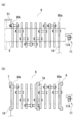
- FIG. 7 is an explanatory diagram showing details of the second embodiment. Note that FIG. 3(b) is a modified example.
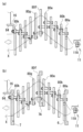
- FIG. 7 is an explanatory diagram showing another modification of the second embodiment. It is an explanatory view showing details of a magnetic field generation part in a 3rd embodiment.
- FIG. 7 is an explanatory diagram showing how the third embodiment is used. It is an explanatory view showing details of a fourth embodiment. These are scanning electron microscope images of experimental results and comparative experiments. It is an explanatory view showing a modification of the embodiment.
- FIG. 7 is an explanatory diagram showing another modification of the embodiment.
- FIG. 7 is an explanatory diagram illustrating another modification.
- FIG. 1 is a diagram schematically showing a film forming apparatus.
- the outline of the film forming apparatus according to the present invention includes a plasma generating means 1, a plasma duct 2 serving as a transport route for evaporated particles whose cathode material is evaporated by the plasma generating means, and a film forming chamber 3 for forming a film. It is configured to include.
- the plasma generating means 1 includes a cathode section 11 and an anode section 12 provided in the vicinity thereof, each of which is connected to an external arc power source 13 via an insulation introduction terminal 4 to enable arc discharge. .
- the cathode section 11 is provided with a cathode 11A made of a film forming material, and this cathode 11A corresponds to a target (evaporation substance raw material).
- a target evaporation substance raw material
- the cathode 11A is configured to also serve as a target
- a film forming material serving as a target may be individually disposed on the surface of the cathode 11A.
- the constituent material of the cathode 11A, which also serves as a target is not particularly limited as long as it is a conductive solid, and metals, alloys, inorganic substances, inorganic compounds, and the like can be used. These can be used alone or as a mixture of two or more. For example, all typical metals and transition metals can be used as simple metals.
- alloys or intermetallic compounds include TiAl, TiCr, TiSi, AlSi, AlCr, and NdFe.
- Inorganic elements include C (graphite), and inorganic compounds (ceramics) include TiO 2 , ZnO, SnO 2 , ITO (Indium-Tin-Oxide), In 2 O 3 , and Cd. 2 There are oxides such as SnO 4 and CuO.
- carbides and nitrides such as TiN, TiAlC, TiC, CrN, and TiCN. There are also mixtures of two or more of them.
- non-metallic materials that can be mixed in the range (semiconductor-like or semi-metallic) that maintains the conductivity of the cathode 11A, such as B, C, Si, P, Ge, As, Se, Sb. , Te, Bi, Po, At, etc.
- atmospheric gases include He, Ar, H2 , N2 , O2 , fluoride gas, hydrocarbon gas, chloride gas, sulfide gas, and mixed gases thereof, including fluorine, hydrogen, carbon, chlorine, Gases or liquid vapors containing sulfur, boron, phosphorus, etc. may also be introduced.
- the material of the anode part 12 is not limited as long as it is conductive and can withstand temperatures of about 200°C.
- An elemental metal, an alloy, an elemental inorganic substance, an inorganic compound, etc. can be used, and the materials exemplified for the cathode can be appropriately selected and used. These can be used alone or as a mixture of two or more.
- stainless steel, soft iron, steel, copper, copper alloy, aluminum, aluminum alloy, graphite, etc. can be used.
- a trigger electrode 14 is provided near the cathode 11A to induce a vacuum arc between the cathode section 11 and anode section 12. That is, by temporarily bringing the trigger electrode 14 into contact with the surface of the cathode 11A and then pulling it away, an electric spark is generated between the cathode 11A and the trigger electrode 14. When an electric spark is generated, the electrical resistance between the cathode section 11 and the anode section 12 decreases, and a vacuum arc is generated between the two pole sections 11 and 12. Furthermore, an arc stabilizing magnetic field generator 15 is installed around the cathode section 11 . This arc stabilizing magnetic field generator 15 is for stabilizing the cathode spot of the vacuum arc and the plasma generated by arc discharge.
- the arc stabilizing magnetic field generator 15 is installed outside the chamber in the figure, it may be installed inside the chamber or behind the cathode section. It is also possible to install multiple units. In other words, a magnetic field that stabilizes the cathode spot and arc discharge and efficiently transports the plasma flow may be applied to the cathode surface and/or the front surface of the cathode.
- a region serving as a transport path for evaporated particles is formed inside the anode portion 12 formed into a substantially cylindrical shape.
- a magnetic field generating section 21 using an electromagnet is provided on the outer periphery of the approximately cylindrical anode section 12, and generates an induction magnetic field that guides charged particles generated by evaporation of the film forming material in a predetermined direction. be. This induced magnetic field is directed along the central axis of the substantially cylindrical anode section 12.
- the charged particles are guided in a region serving as a transport route in a straight line from the cathode part 11 along the central axis direction of the substantially cylindrical anode part 12, and in a straight line from the film forming chamber 3 disposed in front. Charged particles are supplied to the object to be processed A inside through the opening 31. Since this transport route is a straight line, the distance from the cathode section 11 to the object A to be processed can be shortened.
- the film forming chamber 3 is open on the side facing the plasma generation means 1, and is equipped with a workpiece holding means 32 for holding the workpieces A, B,...,H inside.
- a workpiece holding means 32 for holding the workpieces A, B,...,H inside.
- droplets are simultaneously emitted from the cathode spot in addition to electrons and evaporated particles of cathode material.
- the evaporated particles of the cathode material collide with the electrons emitted from the cathode spot, whereby the material is ionized and metal ions and/or nonmetal ions are generated.
- the cathode material evaporated particles are ionized by colliding with electrons immediately after being emitted from the cathode spot. They become neutral particles such as non-ionized cathode material evaporated particles (excluding those that are subsequently ionized), introduced gas particles, and reaction particles, and are unaffected by magnetic and electric fields and proceed straight in the original emission direction.
- the droplets are bumped and ejected at the cathode, but since they also have no charge, they move forward without being affected by magnetic and electric fields.
- FIG. 2 shows the configuration of the plasma generating means 1 of this embodiment.
- the anode side constituting the plasma generating means 1 is provided with a protective member 5 and an electromagnetic coil (magnetic field generating section) 21 electrically connected between the protective member 5.
- the electromagnetic coil 21 is connected to the positive electrode side of the arc power source and enables arc discharge between the cathode section 11 and the protection member 5.
- the protective member 5 is formed of a conductive material into a generally cylindrical shape, and may be made of non-magnetic stainless steel, copper, copper alloy, or the like.
- An electromagnetic coil 21 is provided so as to be wound around the generally cylindrical protection member 5.
- the protective member 5 and the electromagnetic coil 21 are electrically connected by a connecting portion 51 at the edge remote from the cathode portion 11 .
- An end of the electromagnetic coil 21 located farthest from the connection portion 51 is provided so as to be connected to the positive electrode side of the arc power source.
- the protection member 5 made of a conductive material and the electromagnetic coil 21 are provided in a non-contact state so that they are not electrically connected.
- the cathode section 11 At this time, arc discharge occurs between the cathode section 11 and the protection member 5, and the arc plasma X is induced by the magnetic field generated by the electromagnetic coil 21 and flows along the central axis of the protection member 5. . Therefore, the anode part 12 is formed by the entire protective member 5 and the electromagnetic coil 21, but the anode that contributes to the generation of arc discharge is formed by a local part of the protective member 5. . In this embodiment, the protection member 5 functions as an anode.
- the protective member 5 functions to protect the electromagnetic coil (magnetic field generating section) 21. That is, the protective member 5 is placed on the inner circumferential side of the electromagnetic coil 21, and since the arc plasma X flows inside the protective member 5, the protective member 5 is placed between the plasma flow and the electromagnetic coil 21. The situation is as follows. Then, the evaporated particles and droplets included in the emitted substance are also emitted, but among these, the non-ionized particles (neutral particles) and droplets are linearly unaffected by the magnetic field of the electromagnetic coil stone 21. Therefore, it is also emitted in an angular direction (in the direction of the arrow in the figure) with respect to the central axis of the electromagnetic coil 21, regardless of the plasma flow (transport route of evaporated particles).
- the protective member 5 protects the electromagnetic coil 21 from the neutral particles and droplets released in this way. Naturally, since the electromagnetic coil 21 is located outside the protective member 5, evaporated particles other than neutral particles (particles that react with the introduced gas) and ions that have not been strongly influenced by the magnetic field are transferred to the electromagnetic coil 21. 21 can be prevented from adhering to the surface.
- the neutral particles and droplets of the cathode emitted substances that reach the inner surface of the protective member 5 will also adhere to the inner surface of the protective member 5 in the same way as they adhere during film formation. Therefore, the emitted neutral particles and droplets except those that move along the central axis of the electromagnetic coil 21, that is, those that are emitted angularly, can be attached to the protection member 5 and removed. This can prevent adhesion to the magnetic field generating section itself. Furthermore, by attaching the droplets to the protection member 5, the amount of droplets and the like reaching the object to be processed can be reduced. Note that a method for removing droplets (droplets that do not adhere) generated during the formation of the DLC film will be described later.
- the entire anode is constituted by the protection member 5 and the electromagnetic coil 21, that is, the local anode is made to function by the protection member 5, and at the same time, the magnetic field is generated by passing current through the electromagnetic coil 21. Since the structure is configured to cause the evaporation to occur, the distance from the cathode section 11 to the object to be treated can be greatly shortened, thereby reducing the decrease in the density of evaporated substances formed by arc discharge and improving the film formation rate. be able to.
- both ends of the electromagnetic coil 21 (the cathode side and the opposite end) have an outer diameter and an inner diameter with an appropriate dimensional difference.
- This is a configuration in which an annular protection member 6 and an end annular member 7 each having a predetermined wall thickness are arranged. Since the protection member 6 has the annular shape as described above, a surface having a predetermined area in the radial direction of the electromagnetic coil 21 and a surface having a predetermined area in the inner circumferential direction are formed. Furthermore, the annular interior is formed with an inner diameter that is large enough to allow the arc plasma X to pass through.
- the protection member 6 receives evaporation particles and droplets from adhering to it through the two types of surfaces mentioned above, protects the electromagnetic coil 21, and suppresses droplets from reaching the object to be processed. Forming the surface to be large contributes to preventing evaporated particles and droplets from adhering to the electromagnetic coil 21.
- one protective member 6 disposed on the cathode section side has its surface facing the cathode section 11 and its inner peripheral surface disposed closer to the cathode section 11 than the electromagnetic coil 21, so that the electromagnetic coil 21 is protected from the electromagnetic coil 21. Evaporated particles and droplets can be attached before reaching the electromagnetic coil 21 to prevent them from reaching the electromagnetic coil 21.
- the end annular member 7 located on the side opposite to the cathode part receives the attachment of evaporated particles and droplets that have passed through the electromagnetic coil 21. Since this terminal annular member 7 also has a surface and an inner circumferential surface (particularly an inner circumferential surface) facing the cathode section 11, by deliberately allowing droplets to adhere at least, droplets can be emitted in that direction. This prevents the droplets from passing through and preventing them from reaching the object to be processed.
- the protective member 6 and the terminal annular member 7 are made of a conductive material, and the connecting portion 52 between the protective member 6 and the electromagnetic coil 21 provided on the cathode side, and the cathode portion
- the connecting portion 51 between the end annular member 7 and the electromagnetic coil 21 provided on the side opposite to the cathode portion side is both made of a conductive material.
- the member 7 can function as an anode during arc discharge.
- the electrons generated from the cathode 11A mainly move to the protective member 6 made of a conductive material as shown by the broken line arrow, and the electrons move to the electromagnetic coil 21 via the connection part 52.
- the current flows through the electromagnetic coil 21 by sequentially moving along the coil, and the electromagnetic coil 21 can generate a magnetic field. Of course, some electrons reach the electromagnetic coil 21, but they flow through the electromagnetic coil 21 and finally flow from the terminal annular member 7 to the positive pole of the power source. Note that when the protective member 6 and the terminal annular member 7 are made of a non-conductive material, or when the connecting parts 51 and 52 are made of a non-conductive material, the electrons generated from the cathode 11A are transferred to the cathode of the electromagnetic coil 21.
- the electromagnetic coil 21 is moved using the side end as the main starting point, and a current similarly flows through the electromagnetic coil 21.
- the connection to the positive pole of the power supply (power supply connection part 16) is preferably at the farthest position from the cathode part 11 of the electromagnetic coil 21.
- the protective member 6 and the end annular member 7 can be provided for the purpose of controlling the direction of the droplets so that they do not advance toward the object to be treated. That is, the droplets containing graphite material or the like are reflected by the protection member 6 and the terminal annular member 7, and are guided in a direction different from the direction of the object to be processed.
- the structure may be such that the protection member 6 on the cathode side is not provided.
- the evaporated particles will adhere, in order to prevent the evaporated particles from adhering to the electromagnetic coil 21, it is preferable to provide a protective member 6 on the cathode side.
- the anode side can be cooled by making the annular portion interior 71 of the terminal annular member 7, which functions as an anode, hollow and introducing cooling water into this hollow interior 71 (water-cooled It becomes a ring member).
- This cooling structure makes it possible to avoid a temperature rise on the anode side during arc discharge.
- the protection member 6 on the cathode side functions as an anode
- the protection member 6 may be provided with a hollow interior 61 and similarly cooled.
- both 6 and 7 may be formed with hollow interiors 61 and 71, and both 6 and 7 may be water-cooled, regardless of whether or not they are made to function as an anode.
- an annular protection member (partially cut and not necessarily a complete ring) is attached to one end (or both ends may be used) of the approximately cylindrical protection member 5.
- 6 are provided in a connected state and a hollow interior 61 is formed in the annular portion thereof, thereby making it possible to cool with water.
- the substantially cylindrical protection member 5 functions as an anode, but the state in which it is connected to the annular protection member 6 allows it to absorb heat.
- a substantially annular terminal annular member 7 may be disposed on the opposite side to cool the anode side.
- the electromagnetic coil 21 may be formed of a hollow member, and cooling water may be introduced into the hollow member.
- FIG. 4 there is a configuration in which a protection member 6 and a terminal annular member 7 are integrally provided at both ends of a substantially cylindrical protection member 5.
- integrated includes not only integral molding but also integration by physically joining.
- the electromagnetic coil 21 can be protected by the substantially cylindrical protection member 5 and the protection member 6 installed on the cathode side.
- the terminal annular member 7 and the electromagnetic coil 21 are joined by the joining part 51 made of a conductive material, and the protective member 6 and the electromagnetic coil 21 are joined by the joining part 52 made of a non-conductive material, the Electrons move in the same way as in the first embodiment.
- a current electrostatic current of vacuum arc discharge
- the area including the electromagnetic coil 21 functions as an anode.
- the connection to the positive pole of the power supply (power supply connection part 16) is made at a location close to the cathode of the electromagnetic coil 21.
- the connecting portion 52 of the protective member 6 is made of a conductive material and the connecting portion 51 of the opposite end ring member 7 is made of a non-conductive material, the flow of current (electronic current) is reversed.
- the end of the electromagnetic coil 21 that is far from the cathode section 11 functions as the power supply connection section 16 .
- the magnetic field generating section is formed in a generally spiral shape using a plate-like member instead of the electromagnetic coil 21 described above. That is, the electromagnetic coil 21 is made of a conductive material in a coil shape (spiral shape), and is formed into a substantially spiral shape by arranging a plurality of conductive plate members in parallel and sequentially connecting them through the conductive material. That is.
- FIG. 5 shows the magnetic field generating section of this embodiment.
- FIG. 5(a) is an exploded perspective view
- FIG. 5(b) is an overall perspective view.
- the individual conductive plate members 80a to 80e (the figure shows five plates, but the number is arbitrary) constituting the magnetic field generating section 8 are annular plates. It has a substantially horseshoe shape (which may also be expressed as a C-shape) with a portion cut off, and two edges 82a to 82e and 83a to 83e are formed on both sides of the cut portions 81a to 81e.
- These plurality of plate-like members 80a to 80e all have the same shape, are arranged in parallel in sequence, and the adjacent plate-like members 80a to 80e are electrically connected to each other.
- Stainless steel, copper, copper alloy, aluminum, aluminum alloy, graphite, etc. can be used as the conductive plate material.
- the positions of the cut portions 81a to 81e of the plate members 80a to 80e arranged in parallel are sequentially changed at a predetermined angle between adjacent plate members 80a to 80e.
- the positions of the edges 82a to 82e, 83a to 83e located on both sides of the cutting parts 81a to 81e also change, and for example, the first plate member 80a and the second plate member 80b In this relationship, one end edge 82b of the second-order plate-like member 80b is in a positional relationship opposite to the other end edge 83a of the first-order plate-like member 80a.
- the fastening member 9 includes a general bolt 91 and a nut 92, as well as a cylindrical conductive part 93 made of a conductive material, and the conductive part 93 connects two adjacent plate members 80a and 80b. By being placed between them, the two are electrically connected while forming an appropriate distance between them.
- the magnetic field generating section 8 which has a generally cylindrical shape as a whole, as shown in FIG. 5(b).
- a plasma flow can be caused to flow along the inside (center hole) of this approximately annular magnetic field generation section 8.
- the current flows in the same direction in the circumferential direction of each of the plate members 80a to 80e, and passes between two types of opposing edges 82a to 82e and 83a to 83e to the next rank.
- the flow sequentially moves to the plate-like members 80a to 80e, forming a substantially spiral shape.
- symbol 51 in a figure is a connection part with a protection member
- symbol 84 is a connection part for connecting to the positive electrode side of an arc power supply.
- FIG. 6 When using the magnetic field generating section 8 having the above configuration, as shown in FIG. 6, the protective member 5 (see FIG. 6(a)) or the annular protective member 6 (see FIG. 6(b)) is used. can be protected. Note that in order to show the shape of the magnetic field generating section 8, FIG. 6 increases the number of plate-like members 80a to 80k, and does not take into account the dimensional ratio.
- connection part 51 for connection with the protection member 5 is connected to the plate member 80k at one end, and the other plate member 80a is connected to the arc It is provided to be connected to the positive pole of the power supply.
- the protection member 6 when using the same annular protection member 6 as in the second embodiment, the protection member 6 should be placed on the cathode side;
- the members (terminal annular member) 7 and (intermediate annular member) 7A may also be installed at the end (opposite the cathode part) and intermediate positions of the magnetic field generating section 8, respectively.
- the annular portion can be hollow to allow introduction of cooling water.
- the protective member 6 protects the magnetic field generating part 8 from evaporated particles and droplets by the surface of the annular portion, but the evaporated particles and droplets that have passed through the protective member 6 are protected by the plate-like member 80a. It is easily assumed that it will adhere to up to 80k.
- a cooling mechanism may be provided in any of 80a to 80k.
- these plate-like members 80a-80k are integrated by the fastening member 9 (see FIG. 5). ), by releasing this fastening member 9, they can be easily separated, and it is also possible to easily remove (clean) deposits from the separated individual plate-like members 80a to 80k. For the removal operation, it can be removed mechanically, for example, using a lathe or by shot blasting. In addition, chemical removal using chemicals is also facilitated. Note that the cylindrical protective member 5 shown in FIG. 6(a) can also be removed from the magnetic field generating section 8 to easily remove (clean) the deposits. Since each component can be composed of small components, ultrasonic cleaning of the component is easy.
- the fourth embodiment uses substantially horseshoe-shaped plate members 80a to 80k as described above, but has a configuration in which the positions of the plate members 80a to 80k are sequentially displaced in the radial direction of the center hole. be. This state is shown in FIG.
- the individual plate members 80a to 80k all have the same substantially horseshoe shape, but are electrically connected to each other by the fastening member 9, similar to the third embodiment. is connected to. Therefore, the current can flow in a substantially spiral shape as a whole. Then, the individual plate members 80a to 80k are sequentially displaced in the radial direction.
- the displacement state is such that the plate member 80b of the next order is raised in the radial direction from the plate member 80a of the first order.
- the plate member 80f of the sixth rank located in the middle is set as the apex, and the plate members 80g of the seventh rank to the plate member 80k of the final rank are arranged so as to descend one after another. be.
- the entrance and exit positions of the vapor deposition particle transport path can be set in a straight line through all the plate members 80a to 80k. The result is the same as when they are aligned.
- the flow of the arc plasma X (plasma flow) is meandered by the generated magnetic field.
- the neutral particles and droplets move linearly, the neutral particles and droplets emitted from the cathode 11A collide with the surfaces of the individual plate members 80a to 80k.
- the material adheres to the surfaces of these plate-like members 80a to 80k, and in the case of a material that bounces (reflects), it bounces off the surfaces of the plate-like members 80a to 80k, retreats, and is treated. It becomes impossible to move forward in the direction of objects.
- the plate-like member 80a in the first order is subject to collisions with the greatest number of neutral particles and droplets, and those that have passed through these will collide with the plate-like member 80b in the second order.
- the collisions of the droplets will be concentrated on the plate members 80a to 80f located in the first half of the entire magnetic field generating section 8.
- the center hole of the intermediate plate member 80f does not overlap with the center hole of the first plate member 80a due to individual displacement conditions, the subsequent plate members 80g to Neutral particles and droplets will not reach 80k.
- a part of the magnetic field generating part 8 (the first half 80a to 80f) protects the other part (the second half 80g to 80k) without providing a special protection member for the magnetic field generating part 8. be able to.
- the attached neutral particles and droplets can be collected.
- a protective member made of a member different from the magnetic field generating section 8 is not provided, but a part of the magnetic field generating section 8 (a plate-like member disposed on the cathode side) is not provided.
- the members 80a to 80f) function as protective members (substituted as protective members).
- the first plate member 80a can function as an anode.
- the magnetic field generating portion 8 can generate a magnetic field using the self-current (electronic current) of the arc discharge itself.
- annular protective member 6 may be placed on the cathode side as shown in FIG. 7(b).
- annular members (terminal annular member) 7 and (intermediate annular member) 7A having similar configurations are further provided at the intermediate position and the end (on the side opposite to the cathode part side), and these annular parts A configuration may also be adopted in which cooling water is introduced inside.
- the three parts (see the illustration) that correspond to the part where the plasma flow is bent.
- the magnetic field generating section 8 is used as a positive pole section, a part of the magnetic field generating section 8 can function as a protective member, and the plasma flow is meandered by the magnetic field generated by the magnetic field generating section 8.
- the distance required for the meandering is small, the distance from the cathode section 11 to the object to be processed can be shortened as a result. Thereby, it is possible to reduce the decrease in the density of evaporated substances formed by arc discharge and improve the film formation rate.
- Example> an experiment was conducted to confirm the state of film formation when using a magnetic field generating section using a horseshoe-shaped plate member as shown in FIG. 7(a).
- the experimental conditions are as follows. Titanium (Ti) is used as the cathode material, and the horseshoe-shaped plate member used for the anode is made of 15 sheets of oxygen-free copper, with an inner diameter of 100 mm near the center and gradually increasing to 150 mm at both ends.
- the magnetic flux density of the entire horseshoe-shaped magnetic field generating section was about 6 mT.
- the arc current was set to 110A.
- N2 was used as the atmospheric gas, and the introduced flow rate was 30 sccm.
- the chamber internal pressure (film formation pressure) was set to 0.3 Pa, and the film thickness to be formed was adjusted to about 1.8 ⁇ m. Note that the distance between the cathode part and the object to be treated in the apparatus was about 350 mm.
- FIG. 9 shows a modification of the protection member 5 in the first embodiment.
- FIG. 9(a) is a longitudinal sectional view
- FIG. 9(b) is a side view.
- a plurality of protrusions 152 are provided on the inner surface 150B of the cylindrical main body 150 of the protection member 105, so that the inner surface 150B is not flat. Not being flat means that the provision of the projections 152 clearly creates unevenness when compared with the outer surface 150A.
- This protective member 105 is used when droplets emitted from the cathode do not attach to the protective member 105 and bounce (reflect) when graphite or the like is used as a cathode material, such as when forming a DLC film. It is for use. That is, when the inner surface 150B is in a smooth state, it is assumed that the droplets that collide with the surface are reflected toward the object to be processed. However, if a plurality of protrusions 152 are formed on the inner surface 150B, there is a very high possibility that the droplet will collide with any of these protrusions 152.
- the reflection angle of the droplet that collides with the protrusion 152 is greatly changed, making it possible to reduce the proportion of droplets directed toward the object to be processed.
- it when colliding with the protrusion 152, it generally collides with the cathode side surface, so it is assumed that it will be reflected in the backward direction.
- a concave portion may be formed so that the inner surface 150B has an uneven upper surface.
- a protruding part flange part
- this projecting portion flange portion
- this projecting portion may have a structure in which the wall thickness of the annular portion is increased and the annular interior is made hollow to allow introduction of cooling water.
- FIG. 10(a) Another modification is a protection member 205 having the configuration shown in FIG. 10(a).
- the protrusion 252 provided on the inner surface 250B of the main body 250 is annular. Even in such a configuration, the direction of reflection of droplets that collide with the inner surface 250B can be changed.
- the illustrated example has an annular shape, it may also have a spiral shape. Moreover, it may be constructed by a concave ring instead of a projecting ring.
- the flange portion 251 is the same as that of the above-mentioned modification.
- FIG. 10(b) there is a protection member 305 having a configuration shown in FIG. 10(b).
- a plurality of through holes 353 are provided in the main body portion 350.
- the through hole 353 is formed to be long along the generatrix direction of the cylindrical main body portion 350, but may have a short shape, or may have a circular or other shape.
- a long through hole is illustrated.
- the droplets collide and are reflected on the inner surface 350B where the through holes 353 are not provided, but by increasing the proportion of the area penetrated by this type of through holes 353, The probability of that reflection can be reduced.
- the above-mentioned protrusion 152 or the like may be separately formed on this inner surface 350B.
- the flange portion 351 in this modification can also be configured to be used as a connection portion with an electromagnetic coil or the like, or to allow cooling water to be introduced into the annular portion, as in the above-mentioned modification. be.
- the magnetic field generating parts 21 and 8 for inducing the flow of plasma are caused by the arc discharge generated by the plasma generating means. Since a magnetic field is generated by an electric current, the structure from the cathode section 11 to the film forming chamber 3 can be downsized and the positional relationship can be shortened, compared to the case where these are configured individually. By adhering the droplets to the protective members 5, 6 and the terminal annular member 7 over such short distances, or by controlling the direction in which they bounce off the surfaces of the protective members 5, 105, 205, 305, at least the droplets can be It is possible to prevent the film from reaching the film forming chamber 3.
- FIG. 11 is shown as a diagram in a longitudinal cross-sectional view.
- the inner diameters of the annular protection member 6 and the terminal annular member 7 are made smaller than the inner diameter of the cylindrical protection member 5, and the ratio of droplets adhering to the inner surface of the cylindrical protection member 5 is It is also possible to adopt a configuration that reduces the In the case of such a configuration, it is possible to reduce the collision of droplets and the like with the cylindrical protection member 5 (FIG. 11(a)), and it is also possible to reduce droplets and the like from colliding with the cylindrical protection member 5 (FIG.
- cylindrical protection members 5 may be provided with the protrusions 152, 252 in the above-mentioned modification.
- the cylindrical protection member 5 when using the annular protection member 6, if the protection member 6 is not used as an anode (and the power supply connection part 16), the cylindrical protection member 5 Alternatively, it is electrically disconnected from the electromagnetic coil 21, and specifically, it is separated or insulated. Further, when the protection member 6 is made of a non-conductive material, a structure in which the cylindrical protection member and the annular protection member 6 are physically connected may be used.
- These protective members are easy to remove from the anode part, and have a simpler structure as a whole compared to a coiled one, making it easier to remove deposits. For example, it can be removed mechanically using a lathe or shot blasting. Further, chemical removal using chemicals is also easy. Of course, if the deposit is used without removing it, the shape of the coiled structure shown in FIGS. 3 to 4 may be bent as shown in FIG. 7.
- an anode screen may be provided between the anode and the plasma.
- the details of the structure of the anode screen are detailed in Japanese Patent Application Laid-Open No. 5-247630, so illustrations are omitted, but in this case, the anode screen has a structure in which a large number of small diameter holes are provided. In this manner, by providing the anode screen, most of the electrical insulating film material during film formation is deposited on the anode screen, and only the material leaking from the small diameter holes of the anode screen is deposited on the anode.
- the electrically insulating film material is not deposited on the portions shaded by the holes other than the small diameter holes, and it is possible to avoid covering the anode with the electrically insulating film material.
- the arc current electrocurrent of vacuum arc discharge
- punched metal made of stainless steel can be used, but other materials may also be used.
- Plasma generation means 2 Plasma duct 3 Film forming chamber 4 Insulation introduction terminals 5, 6, 7, 105, 205, 305 Protective member 8 Magnetic field generation section 9 Clamping member 11 Cathode section 11A Cathode 12 Anode section 13 Arc power source 14 Trigger electrode 15 Arc stabilizing magnetic field generator 16 Power supply connection part 21 Electromagnetic coils 51, 52 Connection parts 61, 71 Inside of the annular part in the protection member (hollow inside) 80a, 80b, 80c, 80d, 80e, 80f, 80g, 80k Plate member 81a, 81b, 81c, 81d, 81e Cutting portion 82a, 82b, 82c, 82d, 82e End portion of plate member 83a, 83b, 83c, 83d, 83e Another end portion 84 of the plate-like member Connection portion 91 Bolt 92 Nut 93 Conduction portion 150, 250, 350 Cylindrical main body portion 150A of the protective member Outer surface of the main body portion
Landscapes
- Chemical & Material Sciences (AREA)
- Engineering & Computer Science (AREA)
- Physics & Mathematics (AREA)
- Plasma & Fusion (AREA)
- Analytical Chemistry (AREA)
- Materials Engineering (AREA)
- Chemical Kinetics & Catalysis (AREA)
- Mechanical Engineering (AREA)
- Metallurgy (AREA)
- Organic Chemistry (AREA)
- Spectroscopy & Molecular Physics (AREA)
- Plasma Technology (AREA)
- Physical Vapour Deposition (AREA)
Abstract
Description
ここで、本発明の第1の本実施形態について説明する。図2に本実施形態のプラズマ発生手段1の構成を示す。この図に示されるように、プラズマ発生手段1を構成する陽極側には、保護部材5と、この保護部材5との間で電気的に接続される電磁コイル(磁界発生部)21とを備える構成としたものである。電磁コイル21は、アーク電源の正極側に接続され、陰極部11と保護部材5との間でアーク放電を可能とするものである。
本発明の第2の実施形態は、図3(a)に示すように、電磁コイル21の両端(陰極部側およびその反対側の端部)には、外径と内径とが適宜な寸法差を有しつつ所定の肉厚を有してなる円環状の保護部材6および末端円環部材7を配置した構成である。保護部材6は、上記のような円環状としていることから、電磁コイル21の径方向に所定の面積を有する表面と、内径側周方向に所定面積の表面が形成されるものである。しかも環状内部はアークプラズマXを通過させることができる程度の内径によって形成されている。保護部材6は、上記二種類の表面によって、蒸発粒子およびドロップレットの付着を受け、電磁コイル21を保護するとともに、被処理物に対するドロップレットの到達を抑制するためのものであることから、その表面を大きく形成することにより蒸発粒子およびドロップレットが電磁コイル21に付着することの防止に寄与することとなる。
上記第2の実施形態においては、次のような変形例が考えられる。図3(b)に示すように、略円筒状の保護部材5の一端(両端でも良い)に円環状(部分的に切れていて、完完全な輪になってなくてもよい)の保護部材6を接続した状態で設け、その環状部分に中空内部61を構成することにより水冷可能とすることができる。この場合においても、略円筒状の保護部材5が陽極として機能するが、円環状保護部材6と接続した状態により熱を吸収させることができるものとなる。
本発明に係る第3の実施形態は、磁界発生部について、前記の電磁コイル21に代えて、板状部材による略螺旋状を形成するものである。すなわち、電磁コイル21は、導電材料をコイル状(螺旋状)としてなるものであるが、複数の導電性の板状部材を平行に配置し、順次導電材料を介して接続することにより略螺旋状とするものである。
第4の実施形態は、上述のような略馬蹄形の板状部材80a~80kを使用しつつ、当該板状部材80a~80kの位置を中心孔の径方向に順次変位させた構成とするものである。この状態を図7に示す。
ここで、図7(a)に示すような馬蹄形の板状部材を使用した磁界発生部を使用する場合における成膜状態を確認する実験を行った。実験条件は、次のとおりである。陰極材料としてチタン(Ti)を使用し、陽極に使用する馬蹄形の板状部材は、無酸素銅による15枚を用いて、内径は、中央部付近を100mmとし、徐々に両端を150mmとするように100mm~150mmの範囲で配置する構成とし、当該馬蹄形による磁界発生部全体の磁束密度が約6mTとなるものであった。また、アーク電流を110Aとした。雰囲気ガスにはN2を使用し、導入流量を30sccmとした。チャンバ内圧力(成膜圧力)を0.3Paとし、成膜する膜厚を約1.8μmに調整した。なお、装置における陰極部と被処理物との間の距離は約350mmであった。
次に、上述の実施形態における変形例について説明する。図9は、第1の実施形態における保護部材5の変形例である。なお、図9(a)は縦断面図であり、(b)は側面図である。この図に示すように、この変形例は、保護部材105の円筒状本体部150の内側表面150Bに複数の突起部152を設けて、当該内側表面150Bを平坦でない状態としたものである。平坦でないとは、外側表面150Aとの比較において、明らかに突起部152を設けたことにより凹凸を生じさせた状態を意味するものである。
以上のとおり、上記のような実施形態および変形例に示すように、これらの形態によれば、プラズマの流れを誘導するための磁界発生部21,8は、プラズマ発生手段により発生するアーク放電による電流によって磁界を発生させるものであるから、これらを個別に構成する場合に比較して、陰極部11から成膜室3までの構成を小型化でき、位置関係を短くすることもできる。このように短い距離において、ドロップレットを保護部材5,6および末端円環部材7に付着させ、または保護部材5,105,205,305の表面で跳ね返る方向を制御させることで、少なくともドロップレットを成膜室3に到達することを抑制することができる。
2 プラズマダクト
3 成膜室
4 絶縁導入端子
5,6,7,105,205,305 保護部材
8 磁界発生部
9 締着部材
11 陰極部
11A 陰極
12 陽極部
13 アーク電源
14 トリガ電極
15 アーク安定化磁界発生器
16 電源接続部
21 電磁コイル
51,52 接続部61,71 保護部材における環状部分の内部(中空内部)
80a,80b,80c,80d,80e,80f,80g,80k 板状部材
81a,81b,81c,81d,81e 切断部
82a,82b,82c,82d,82e 板状部材の端部
83a,83b,83c,83d,83e 板状部材のもう一つの端部
84 接続部
91 ボルト
92 ナット
93 導通部
150,250,350 保護部材における円筒状の本体部
150A 保護部材における本体部の外側表面
150B,250B,350B 保護部材における本体部の内側表面
151,251,351 フランジ部(接続部)
152 突起部
252 突起部(環状)
353 貫通孔
X アークプラズマ
Claims (11)
- 真空中で電源を介して接続される陰極と陽極との間にアーク放電を行ってプラズマを発生させるプラズマ発生手段を備え、前記陰極を構成する陰極材料を蒸発させて被処理物の表面に膜を蒸着形成する成膜装置において、
前記プラズマ発生手段は、
陰極部と、
該陰極部から適宜間隔を有して配置される陽極部と、
該陽極部によって構成され、または該陽極部と一体的もしくは連続的に構成され、アーク放電自体の自己電流によって磁界を発生させる磁界発生部と、
前記陽極部の一部によって構成され、もしくは該陽極部に電気的に接続されつつ独立して構成され、または前記磁界発生部の一部によって代用され、該磁界発生部とプラズマとの間の位置に配置されて該磁界発生部の一部または全部を陰極材料から保護する保護部材と
を備えることを特徴とする成膜装置。 - 前記磁界発生部は、プラズマ流が流動する領域の周辺に略筒状に形成されており、
前記保護部材は、略筒状に形成される前記磁界発生部のうち、陰極部側またはその反対側に位置する少なくとも一方の端縁に配置され、該磁界発生部の径方向に適宜面積の表面を有しつつ内部に冷却水を導入するための中空部を有する水冷用リング部材によって構成されるものである請求項1に記載の成膜装置。 - 前記磁界発生部は、プラズマ流が流動する領域の周辺に略筒状に形成されており、
前記保護部材は、プラズマ流が流動する領域と前記磁界発生部との間に配置される筒状の部材によって構成されるものである請求項1に記載の成膜装置。 - 前記保護部材は、複数の貫通孔を有するものである請求項3に記載の成膜装置。
- 前記保護部材は、少なくとも内側表面が平坦でない状態に形成してなるものである請求項3に記載の成膜装置。
- 前記保護部材の内側表面は、該保護部材の複数箇所において部分的に切り込みを設けて一部を折曲させて立設してなる多数の立設部、適宜箇所を穿孔してなる多数の貫通孔、適宜間隔を凹状に形成してなる複数の凹状部、適宜間隔を凸状に形成してなる多数の突起部、または略筒状の周方向に連続的に突出させた複数の環状突起部の中から選択される形状としている請求項5に記載の成膜装置。
- 前記磁界発生部は、導電性材料を螺旋状に連続して構成され、または中空の導電性材料を螺旋状に連続して構成されたコイル状磁界発生部である請求項1~6のいずれかに記載の成膜装置。
- 前記磁界発生部は、適宜間隔で配置された複数の導電性の板状部材によって構成されるものであり、該板状部材は、円環の一部に切断部を有する略馬蹄形に設けられ、板状部材の切断部両側の端縁のうち一方が、隣接する板状部材の他方の端縁との間で導通され、アーク放電による電流が順次隣接する板状部材を略螺旋状に流れるように構成されている請求項1~6のいずれかに記載の成膜装置。
- 前記板状部材は、略馬蹄形の中心位置をプラズマ流が流動する方向に対して有角方向に順次変位させて配置し、前記磁界発生部の中心孔を蛇行させるものである請求項8に記載の成膜装置。
- 前記磁界発生部は、前記板状部材の始端側から終端側までの任意の位置に中空円環状の水冷用リング部材が配置されている請求項9に記載の成膜装置。
- 前記磁界発生部は、0.01~20mTの範囲内における磁束密度による磁界を発生させるものである請求項1~10のいずれかに記載の成膜装置。
Priority Applications (6)
| Application Number | Priority Date | Filing Date | Title |
|---|---|---|---|
| PCT/JP2022/017073 WO2023195058A1 (ja) | 2022-04-04 | 2022-04-04 | 成膜装置 |
| EP22936458.3A EP4506484A4 (en) | 2022-04-04 | 2022-04-04 | Film-forming device |
| KR1020247031127A KR20240152366A (ko) | 2022-04-04 | 2022-04-04 | 성막 장치 |
| US18/849,892 US20250210320A1 (en) | 2022-04-04 | 2022-04-04 | Film-forming device |
| JP2024513586A JP7847296B2 (ja) | 2022-04-04 | 2022-04-04 | 成膜装置 |
| CN202280093473.3A CN118786239A (zh) | 2022-04-04 | 2022-04-04 | 成膜装置 |
Applications Claiming Priority (1)
| Application Number | Priority Date | Filing Date | Title |
|---|---|---|---|
| PCT/JP2022/017073 WO2023195058A1 (ja) | 2022-04-04 | 2022-04-04 | 成膜装置 |
Publications (1)
| Publication Number | Publication Date |
|---|---|
| WO2023195058A1 true WO2023195058A1 (ja) | 2023-10-12 |
Family
ID=88242648
Family Applications (1)
| Application Number | Title | Priority Date | Filing Date |
|---|---|---|---|
| PCT/JP2022/017073 Ceased WO2023195058A1 (ja) | 2022-04-04 | 2022-04-04 | 成膜装置 |
Country Status (6)
| Country | Link |
|---|---|
| US (1) | US20250210320A1 (ja) |
| EP (1) | EP4506484A4 (ja) |
| JP (1) | JP7847296B2 (ja) |
| KR (1) | KR20240152366A (ja) |
| CN (1) | CN118786239A (ja) |
| WO (1) | WO2023195058A1 (ja) |
Cited By (3)
| Publication number | Priority date | Publication date | Assignee | Title |
|---|---|---|---|---|
| CN119811976A (zh) * | 2025-03-17 | 2025-04-11 | 温州职业技术学院 | 直管磁过滤径向电弧源 |
| WO2025187067A1 (ja) * | 2024-03-08 | 2025-09-12 | 国立大学法人豊橋技術科学大学 | 真空アーク蒸着用の蒸発源装置および真空アーク蒸着装置 |
| WO2026033609A1 (ja) * | 2024-08-05 | 2026-02-12 | 国立大学法人豊橋技術科学大学 | 成膜装置における真空アーク放電安定化構造 |
Citations (5)
| Publication number | Priority date | Publication date | Assignee | Title |
|---|---|---|---|---|
| JPH05247630A (ja) | 1992-03-05 | 1993-09-24 | Nissin Electric Co Ltd | 真空アーク蒸着装置 |
| WO2006104055A1 (ja) * | 2005-03-25 | 2006-10-05 | Ferrotec Corporation | プラズマ生成装置におけるドロップレット除去装置及びドロップレット除去方法 |
| WO2008038700A1 (en) * | 2006-09-30 | 2008-04-03 | Ferrotec Corporation | Radially enlarged type plasma generating apparatus |
| JP2008248347A (ja) * | 2007-03-30 | 2008-10-16 | Ferrotec Corp | プラズマガン周辺を電気的中性にしたプラズマ生成装置 |
| JP2017122266A (ja) * | 2016-01-07 | 2017-07-13 | キヤノンアネルバ株式会社 | 成膜装置 |
Family Cites Families (5)
| Publication number | Priority date | Publication date | Assignee | Title |
|---|---|---|---|---|
| DE19739527C2 (de) * | 1997-09-09 | 2003-10-16 | Rossendorf Forschzent | Vakuumbogen-Plasmaquelle mit Magnet-Partikelfilter |
| JP3865570B2 (ja) | 2000-06-16 | 2007-01-10 | 伊藤光学工業株式会社 | プラズマ加工法 |
| JP4000764B2 (ja) * | 2000-09-18 | 2007-10-31 | 日新電機株式会社 | 真空アーク蒸発装置 |
| US20020070647A1 (en) * | 2000-12-11 | 2002-06-13 | Andrey Ginovker | Nanostructure plasma source |
| JP4319556B2 (ja) | 2004-01-28 | 2009-08-26 | 浩史 滝川 | プラズマ生成装置 |
-
2022
- 2022-04-04 US US18/849,892 patent/US20250210320A1/en active Pending
- 2022-04-04 KR KR1020247031127A patent/KR20240152366A/ko active Pending
- 2022-04-04 JP JP2024513586A patent/JP7847296B2/ja active Active
- 2022-04-04 CN CN202280093473.3A patent/CN118786239A/zh active Pending
- 2022-04-04 EP EP22936458.3A patent/EP4506484A4/en active Pending
- 2022-04-04 WO PCT/JP2022/017073 patent/WO2023195058A1/ja not_active Ceased
Patent Citations (5)
| Publication number | Priority date | Publication date | Assignee | Title |
|---|---|---|---|---|
| JPH05247630A (ja) | 1992-03-05 | 1993-09-24 | Nissin Electric Co Ltd | 真空アーク蒸着装置 |
| WO2006104055A1 (ja) * | 2005-03-25 | 2006-10-05 | Ferrotec Corporation | プラズマ生成装置におけるドロップレット除去装置及びドロップレット除去方法 |
| WO2008038700A1 (en) * | 2006-09-30 | 2008-04-03 | Ferrotec Corporation | Radially enlarged type plasma generating apparatus |
| JP2008248347A (ja) * | 2007-03-30 | 2008-10-16 | Ferrotec Corp | プラズマガン周辺を電気的中性にしたプラズマ生成装置 |
| JP2017122266A (ja) * | 2016-01-07 | 2017-07-13 | キヤノンアネルバ株式会社 | 成膜装置 |
Non-Patent Citations (2)
| Title |
|---|
| ANDRE ANDERS: "Approaches to rid cathodic arc plasmas of macro- and nanoparticles: a review", SURFACE AND COATINGS TECHNOLOGY, vol. 120-121, 1999, pages 319 - 330 |
| See also references of EP4506484A4 |
Cited By (3)
| Publication number | Priority date | Publication date | Assignee | Title |
|---|---|---|---|---|
| WO2025187067A1 (ja) * | 2024-03-08 | 2025-09-12 | 国立大学法人豊橋技術科学大学 | 真空アーク蒸着用の蒸発源装置および真空アーク蒸着装置 |
| WO2026033609A1 (ja) * | 2024-08-05 | 2026-02-12 | 国立大学法人豊橋技術科学大学 | 成膜装置における真空アーク放電安定化構造 |
| CN119811976A (zh) * | 2025-03-17 | 2025-04-11 | 温州职业技术学院 | 直管磁过滤径向电弧源 |
Also Published As
| Publication number | Publication date |
|---|---|
| KR20240152366A (ko) | 2024-10-21 |
| CN118786239A (zh) | 2024-10-15 |
| EP4506484A1 (en) | 2025-02-12 |
| JPWO2023195058A1 (ja) | 2023-10-12 |
| EP4506484A4 (en) | 2025-04-23 |
| US20250210320A1 (en) | 2025-06-26 |
| JP7847296B2 (ja) | 2026-04-17 |
Similar Documents
| Publication | Publication Date | Title |
|---|---|---|
| WO2023195058A1 (ja) | 成膜装置 | |
| JP6625793B2 (ja) | 減圧アークプラズマ浸漬皮膜蒸着及びイオン処理 | |
| EP2788522B1 (en) | Filtered cathodic arc deposition apparatus and method | |
| CN104561916B (zh) | 真空涂覆和等离子体处理系统及用于涂覆衬底的方法 | |
| US20140076716A1 (en) | Low Pressure Arc Plasma Immersion Coating Vapor Deposition And Ion Treatment | |
| EP3091560A1 (en) | Remote arc discharge plasma assisted system | |
| US20020070647A1 (en) | Nanostructure plasma source | |
| EP1862565B1 (en) | Droplet removing device and method in plasma generator | |
| CN102471869B (zh) | 阳极壁多分割型等离子发生装置及等离子处理装置 | |
| EP2586888B1 (en) | Arc evaporation source having fast film-forming speed, film formation device and manufacturing method for coating film using the arc evaporation source | |
| US6756596B2 (en) | Filtered ion source | |
| US12503756B2 (en) | Apparatus and method for coating the inner surface of a hollow article | |
| US9624570B2 (en) | Compact, filtered ion source | |
| KR101075152B1 (ko) | 이중굴곡 플라즈마 덕트를 구비한 진공아크 증착장치 | |
| EP4334488A1 (en) | A system and a method for plasma surface treatment | |
| WO2026033609A1 (ja) | 成膜装置における真空アーク放電安定化構造 | |
| JP2020507677A (ja) | 所定のカソード材料除去を伴うカソードアーク蒸発 | |
| KR20170056880A (ko) | 성막장치 및 성막체의 제조방법 |
Legal Events
| Date | Code | Title | Description |
|---|---|---|---|
| 121 | Ep: the epo has been informed by wipo that ep was designated in this application |
Ref document number: 22936458 Country of ref document: EP Kind code of ref document: A1 |
|
| WWE | Wipo information: entry into national phase |
Ref document number: 202280093473.3 Country of ref document: CN |
|
| ENP | Entry into the national phase |
Ref document number: 20247031127 Country of ref document: KR Kind code of ref document: A |
|
| WWE | Wipo information: entry into national phase |
Ref document number: 1020247031127 Country of ref document: KR |
|
| WWE | Wipo information: entry into national phase |
Ref document number: 18849892 Country of ref document: US |
|
| ENP | Entry into the national phase |
Ref document number: 2024513586 Country of ref document: JP Kind code of ref document: A |
|
| WWE | Wipo information: entry into national phase |
Ref document number: 202417074319 Country of ref document: IN |
|
| WWE | Wipo information: entry into national phase |
Ref document number: 2022936458 Country of ref document: EP |
|
| NENP | Non-entry into the national phase |
Ref country code: DE |
|
| ENP | Entry into the national phase |
Ref document number: 2022936458 Country of ref document: EP Effective date: 20241104 |
|
| WWP | Wipo information: published in national office |
Ref document number: 18849892 Country of ref document: US |