WO2023195219A1 - 発汗量計測装置及び発汗量計測システム - Google Patents
発汗量計測装置及び発汗量計測システム Download PDFInfo
- Publication number
- WO2023195219A1 WO2023195219A1 PCT/JP2023/003207 JP2023003207W WO2023195219A1 WO 2023195219 A1 WO2023195219 A1 WO 2023195219A1 JP 2023003207 W JP2023003207 W JP 2023003207W WO 2023195219 A1 WO2023195219 A1 WO 2023195219A1
- Authority
- WO
- WIPO (PCT)
- Prior art keywords
- measuring device
- sweat
- amount measuring
- temperature
- air
- Prior art date
- Legal status (The legal status is an assumption and is not a legal conclusion. Google has not performed a legal analysis and makes no representation as to the accuracy of the status listed.)
- Ceased
Links
Images


Classifications
-
- A—HUMAN NECESSITIES
- A61—MEDICAL OR VETERINARY SCIENCE; HYGIENE
- A61B—DIAGNOSIS; SURGERY; IDENTIFICATION
- A61B5/00—Measuring for diagnostic purposes; Identification of persons
- A61B5/145—Measuring characteristics of blood in vivo, e.g. gas concentration or pH-value ; Measuring characteristics of body fluids or tissues, e.g. interstitial fluid or cerebral tissue
- A61B5/14507—Measuring characteristics of blood in vivo, e.g. gas concentration or pH-value ; Measuring characteristics of body fluids or tissues, e.g. interstitial fluid or cerebral tissue specially adapted for measuring characteristics of body fluids other than blood
- A61B5/14517—Measuring characteristics of blood in vivo, e.g. gas concentration or pH-value ; Measuring characteristics of body fluids or tissues, e.g. interstitial fluid or cerebral tissue specially adapted for measuring characteristics of body fluids other than blood for sweat
-
- A—HUMAN NECESSITIES
- A42—HEADWEAR
- A42B—HATS; HEAD COVERINGS
- A42B3/00—Helmets; Helmet covers ; Other protective head coverings
- A42B3/04—Parts, details or accessories of helmets
- A42B3/0406—Accessories for helmets
- A42B3/0433—Detecting, signalling or lighting devices
- A42B3/046—Means for detecting hazards or accidents
-
- A—HUMAN NECESSITIES
- A42—HEADWEAR
- A42B—HATS; HEAD COVERINGS
- A42B3/00—Helmets; Helmet covers ; Other protective head coverings
- A42B3/04—Parts, details or accessories of helmets
- A42B3/28—Ventilating arrangements
- A42B3/286—Ventilating arrangements with forced flow, e.g. by a fan
-
- A—HUMAN NECESSITIES
- A61—MEDICAL OR VETERINARY SCIENCE; HYGIENE
- A61B—DIAGNOSIS; SURGERY; IDENTIFICATION
- A61B5/00—Measuring for diagnostic purposes; Identification of persons
- A61B5/68—Arrangements of detecting, measuring or recording means, e.g. sensors, in relation to patient
- A61B5/6801—Arrangements of detecting, measuring or recording means, e.g. sensors, in relation to patient specially adapted to be attached to or worn on the body surface
- A61B5/6802—Sensor mounted on worn items
- A61B5/6803—Head-worn items, e.g. helmets, masks, headphones or goggles
-
- A—HUMAN NECESSITIES
- A61—MEDICAL OR VETERINARY SCIENCE; HYGIENE
- A61B—DIAGNOSIS; SURGERY; IDENTIFICATION
- A61B2560/00—Constructional details of operational features of apparatus; Accessories for medical measuring apparatus
- A61B2560/02—Operational features
- A61B2560/0242—Operational features adapted to measure environmental factors, e.g. temperature, pollution
- A61B2560/0247—Operational features adapted to measure environmental factors, e.g. temperature, pollution for compensation or correction of the measured physiological value
- A61B2560/0252—Operational features adapted to measure environmental factors, e.g. temperature, pollution for compensation or correction of the measured physiological value using ambient temperature
Definitions
- the present invention relates to a sweat amount measuring device and a sweat amount measuring system.
- the sweat amount measuring device described in Non-Patent Document 2 and Patent Document 1 uses a fan to extract air existing in the space (air flow path inside the helmet) formed between the outer shell of the helmet and the wearer's head. This allows for forced movement. After doing so, the temperature t 1 and relative humidity RH 1 of the air flowing into the air flow path inside the helmet are measured to calculate the amount of moisture per unit volume (inflow moisture amount X 1 ), and the amount of water flowing from the air flow path inside the helmet is calculated. The temperature t 2 and relative humidity RH 2 of the outflowing air are measured to calculate the amount of moisture per unit volume (outflow amount of moisture X 2 ). By subtracting the inflow moisture amount X 1 from the calculated outflow moisture amount ) can be obtained.
- Non-Patent Document 2 Research has shown that there is a sufficient correlation between the amount of head sweat and the amount of whole body sweat (see Non-Patent Document 2). can be estimated.
- the wearable sweat measurement device using a helmet estimates the amount of sweat from the whole body based on the measured value of the amount of sweat on the head, so it is important to measure the amount of sweat on the head as accurately as possible. is important.
- the techniques described in Non-Patent Document 2 and Patent Document 1 are measurement methods that can be used with a specific helmet equipped with a fan.
- helmets made by various manufacturers are used, and it is difficult to widely measure perspiration based on a specific helmet equipped with a fan.
- there is a demand for a sweat amount measuring device that can be widely attached to a general helmet without a fan and that can more accurately measure the amount of perspiration of the head at construction sites and the like.
- the present invention has been made in view of the above-mentioned circumstances, and provides a sweat amount measuring device that can be widely attached to general helmets without a fan and that can measure the amount of sweat on the head more accurately than before.
- the purpose is to provide.
- Another object of the present invention is to provide a sweat amount measuring system including such a sweat amount measuring device.
- a sweat amount measuring device that is attached to the edge of a helmet and measures the amount of sweat from the head of a wearer of the helmet.
- the sweat amount measuring device is placed in an air flow path through which air containing water vapor emitted from the head (hereinafter referred to as “inner air”) flows, and in a place open to the outside world, and is A first temperature and humidity sensor that measures the temperature and relative humidity of the outside air (hereinafter referred to as "outside air”) taken in from the opposite side of the air passage, and a first temperature and humidity sensor that sucks the inside air in the air flow path.
- a fan that discharges the internal air to the outside of the perspiration measuring device; and a second temperature/humidity device that is placed in the middle of the internal air flow generated by the operation of the fan and measures the temperature and relative humidity of the internal air.
- a sensor that is placed in the middle of the internal air flow generated by the operation of the fan and measures the temperature and relative humidity of the internal air.
- a sweat amount measuring system including a helmet and the sweat amount measuring device described above attached to the edge of the helmet.
- a sweat amount measuring device that can be widely attached to general helmets without a fan and can measure the amount of sweat on the head more accurately than before.
- FIG. 2 is a schematic cross-sectional view showing a sweat amount measuring device 1 according to a first embodiment and a sweat amount measuring system 9 according to a third embodiment.
- FIG. 2 is a front view showing only the sensor cover 50 when the sweat amount measuring device 1 of FIG. 1 is viewed along arrow P.
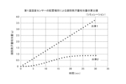
- FIG. This is a graph in which the cumulative amount equivalent to the amount of head perspiration is calculated and plotted by simulation while changing the level by changing the placement location of the first temperature/humidity sensor 20.
- 2 is a schematic cross-sectional view showing a sweat amount measuring device 2 according to a second embodiment and a sweat amount measuring system 9' according to a third embodiment.
- FIG. 5 is a front view showing only the sensor cover 50 when the sweat amount measuring device 4 of FIG.
- FIG. 1 is a diagram showing an example of a sweat amount measuring device 2.
- FIG. FIG. 2 is a block diagram showing an example of an electrical hardware configuration implemented in the sweat amount measuring devices 1, 2, and the like.
- FIG. 7 is a front view showing sensor covers 50' and 50'' of Modifications 1 and 2, respectively.
- FIG. 3 is a schematic cross-sectional view showing a sweat amount measuring device 3 according to a third modification.
- FIG. 4 is a schematic cross-sectional view showing a sweat amount measuring device 4 according to a fourth modification.
- 12 is a schematic cross-sectional view showing a sweat amount measuring device 5 according to a fifth modification.
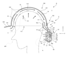
- FIG. 1 is a schematic cross-sectional view showing the sweat amount measuring device 1 according to the first embodiment and the sweat amount measuring system 9 according to the third embodiment.
- Arrows indicated by IA and OA in the figure are for illustratively explaining a portion of the inside air IA and outside air OA flowing into the space. The direction of the arrow here indicates the direction in which air travels (the same applies to the following drawings).
- FIG. 2 is a front view showing only the sensor cover 50 when the sweat amount measuring device 1 of FIG. 1 is viewed along arrow P.
- the sweat amount measuring device 1 As shown in FIG. 1, the sweat amount measuring device 1 according to the first embodiment is attached to the edge 102 of a helmet 100, and is connected to the head H of the wearer WR of the helmet 100. This device measures the amount of sweat per person.
- the sweat amount measuring device 1 includes a helmet attachment means (no reference numeral) for attaching the sweat amount measuring device 1 to the helmet 100.
- the sweat amount measuring device 1 is provided with a clip portion 92, and this clip portion 92 constitutes a helmet attachment means.
- the clip portion 92 includes a clip inner peripheral material 92a, a clip outer peripheral material 92b, and a clip side peripheral material 92c (see also FIG. 6(a)).
- An opening 12 is provided on one side (the upper side in the figure) of the clip portion 92, and when the edge 102 (rear edge) of the helmet 100 is inserted into the opening 12, the edge 102 of the helmet 100 is inserted into the opening 12. is sandwiched and fixed between the clip inner peripheral material 92a and the clip outer peripheral material 92b. As a result, the sweat amount measuring device 1 is attached to the helmet 100.
- the sweat amount measuring device 1 includes an air flow path 10, a first temperature/humidity sensor 20, a fan 30, and a second temperature/humidity sensor 40.
- the sweat amount measuring device 1 rotates the fan 30 to draw air from the outside world E (outside air OA) into the helmet 100, and flows air containing water vapor (inner air IA) emitted from the head H inside the helmet 100.
- the first temperature/humidity sensor 20 and the second temperature/humidity sensor 40 measure the air flowing into and out of the space system.
- the “external world E” refers to the outer shell 101 (semispherical) of the helmet 100 and the sweat amount measuring device 1 when the sweat amount measuring device 1 is attached to the helmet 100 and worn on a person. Refers to the area outside of the area surrounded by 1. In other words, the “external world E” refers to an area on the opposite side of the outer shell 101 of the helmet 100 or the sweat amount measuring device 1, rather than on the wearer WR side. Moreover, in a narrow sense, it can also be said to be an area outside the space in which the internal air IA (described later) flows.
- the air flow path 10 is a structure through which air containing water vapor (inner air IA) emitted from the head H of the wearer WR flows.
- the air flow path 10 is surrounded by walls such as an inner clip member 92a, an outer clip member 92b, an inner wall 96b and a bottom 96a of a closing portion 96 (described later), and a shielding member 94 (described later).
- the air flow path 10 has an opening 12 formed by one end of each of the inner clip member 92a and the outer clip member 92b.
- a space connected from the opening 12 to the inside of the closing portion 96 constitutes an air flow path 10.
- the opening 12 is connected to an intra-helmet air flow path 110, which is a space between the helmet 100 and the head H, so that internal air IA can be taken in through the opening 12.
- the first temperature/humidity sensor 20 is a sensor for measuring the amount of moisture X (sometimes referred to as absolute humidity X) contained per unit volume of the outside air OA.
- the first temperature and humidity sensor 20 is placed in a place open to the outside world E, and air from the outside world E (outside air OA) taken in from a place on the side opposite to the side of the wearer WR when viewed from the air flow path 10.
- the first temperature and humidity sensor 20 is electrically connected to the control unit 70 by wire or wirelessly (see FIG. 7), and transmits the sensed measurement value to the control unit 70.
- the first temperature/humidity sensor 20 is arranged at a location opposite to the wearer WR side when viewed from the air flow path 10 through which the internal air IA flows. Specifically, the first temperature/humidity sensor 20 is disposed on the surface of the shielding member 94 opposite to the surface facing the wearer WR.
- the first temperature and humidity sensor 20 may be exposed to the outside E.
- the structure of the sweat amount measuring device 1 can be simplified and the weight of the sweat amount measuring device 1 can be reduced by not using the cover. can.
- the first temperature/humidity sensor 20 is further covered with a sensor cover 50 so that the first temperature/humidity sensor 20 is less susceptible to the effects of radiant heat from the outside, particularly sunlight.
- the sweat amount measuring device 1 is provided with a sensor cover 50 that covers the first temperature and humidity sensor 20.
- the sensor cover 50 has an outside air intake 52 located on the opposite side of the wearer WR from the air flow path 10 and approximately below the first temperature/humidity sensor 20.
- the outside air OA can be taken in from such an opening location where it is less affected by the contamination of heat, water vapor, etc. emitted by the wearer WR.
- an outside air outlet 53 is provided approximately above the first temperature/humidity sensor 20 to increase the fluidity of the air within the sensor cover 50 and to suppress variations in temperature occurring within the sensor cover 50. It has become.
- the first temperature/humidity sensor 20 spatially communicates with the outside world E through an outside air intake port 52 and an outside air takeout port 53, and is disposed at a location open to the outside world.
- the sensor cover 50 of the sweat amount measuring device 1 is provided with an outside air outlet 53 in addition to the outside air intake 52, and the outside air OA flows into the inner space where the first temperature and humidity sensor 20 is arranged. It is now possible to make The first temperature and humidity sensor 20 is arranged in "the space 60 where the outside air OA flows". Note that the sweat amount measuring device 1 may have a configuration in which the sensor cover 50 does not have the outside air outlet 53 but only has the outside air intake 52.
- Fan 30 forces the air present in the space system formed by the air flow path 10 and the in-helmet air flow path 110 to flow.
- Fan 30 is located adjacent to air flow path 10 .
- the fan 30 is electrically connected to the control unit 70 (see FIG. 7), and uses a drive signal or drive power supplied from the control unit 70 to move air from inside to outside the air flow path 10 (the sweat amount measuring device concerned).
- the rotation is controlled in the direction in which it is sent to the outside of
- the fan 30 sucks the internal air IA within the air flow path 10 and discharges the internal air IA to the outside of the sweat amount measuring device 1 .
- negative pressure is generated in the air flow path 10 and the in-helmet air flow path 110.
- the position where the fan 30 is arranged is such that when the perspiration measuring device 1 is attached to the edge 102 of the helmet 100, the air is discharged from the back of the wearer's head to the nape N of the wearer's neck. It is set to be.
- the opening on the side where air is taken in in the fan 30 is defined as a fan intake port 31, and the opening on the side where air is discharged is defined as a fan discharge port 32.
- the structure designated by numeral 39 is a fan guard.
- Second temperature/humidity sensor 40 is a sensor for measuring the amount of moisture X 2 (sometimes referred to as absolute humidity X 2 ) contained per unit volume of the internal air IA.
- the second temperature/humidity sensor 40 is disposed midway through the flow of the internal air IA generated by the operation of the fan 30, and measures the temperature and relative humidity of the internal air IA.
- the second temperature/humidity sensor 40 is electrically connected to the control unit 70 by wire or wirelessly (see FIG. 7), and transmits the sensed measurement value to the control unit 70.
- temperature and humidity sensors include a form in which the temperature sensor and the humidity sensor are integrated, and a form in which the temperature sensor and the humidity sensor are separated. It also includes formalized forms.
- Closure portion 96 of air flow path 10 has a closure portion 96 formed adjacent to fan 30 .
- the overall shape of the air flow path 10 is a so-called cul-de-sac, with a dead end near the end of the blocking section 96 (bottom 96a of the blocking section 96) when the opening 12 is defined as an "inlet".
- the fan 30 is arranged adjacent to and parallel to the longitudinal direction of the air flow path 10 near the end of the closing portion 96 of the air flow path 10 .
- the internal air IA flowing through the air flow path 10 is exhausted by the fan 30 from near the end of the closing portion 96.
- the second temperature/humidity sensor 40 is disposed inside the closed portion 96 of the air flow path 10.
- the second temperature/humidity sensor 40 is preferably disposed on the upstream side of the fan 30 (on the side of the fan suction port 31 when viewed from the fan 30).
- the second temperature/humidity sensor 40 is arranged at a position facing the fan 30 on the inner wall 96b of the closed section (here, the wall of the shielding member 94 also constitutes the inner wall of the closed section). ing.
- the second temperature/humidity sensor 40 may be placed on the downstream side of the fan 30 (on the fan outlet 32 side when viewed from the fan 30).
- the sweat amount measuring device 1 can basically measure the head sweat amount Y using the principle of sweat amount measurement described in Non-Patent Document 2. However, the first embodiment is not limited to this.
- the sweat amount measuring device 1 when the space formed between the outer shell 101 of the helmet 100 and the head H of the wearer WR is defined as the in-helmet air channel 110, the sweat flows into the in-helmet air channel 110.
- the temperature t 1 and relative humidity RH 1 of the outside air OA which is air in the outside world E or air equivalent thereto, are measured by the first temperature and humidity sensor 20 to calculate the amount of moisture per unit volume as the amount of inflow moisture X 1 .
- the temperature t2 and relative humidity RH2 of the internal air IA generated in the internal air flow path 110 in the helmet are measured by the second temperature/humidity sensor 40 to calculate the moisture content per unit volume as the outflow moisture content X2 .
- the head perspiration amount Y which is the perspiration amount from the head H, is calculated based on the inflow moisture amount X 1 , the outflow moisture amount X 2 , and the air volume F related to the exhaust of the internal air IA by the fan 30. Specifically, the head sweat amount Y is calculated by subtracting the inflow moisture amount X 1 from the outflow moisture amount X 2 and multiplying this by the air flow rate F. Furthermore, the amount of whole body sweat can be estimated based on the calculated head sweat amount Y.
- a measuring device for performing measurement based on such a principle can maximize the functions and effects of the sweat amount measuring device 1 according to the first embodiment.
- the measuring device has the configuration of the sweat amount measuring device 1 according to the first embodiment, the head sweat amount or the whole body sweat amount can be measured more accurately based on the above-described principle. Note that details regarding the calculation of the head sweat amount Y will be discussed later in [Example].
- the fan shall exhaust the internal air in the helmet air channel or air channel.
- the temperature and relative humidity of the internal air are determined by the second temperature and humidity sensor to determine the amount of water flowing out.
- the first temperature and humidity sensor determines the temperature and relative humidity of the outside air (outside air) flowing into the helmet to determine the amount of water flowing out.
- the principle of sweat amount measurement described in Non-Patent Document 2 is used.
- the second temperature and humidity sensor is placed in the immediate vicinity of the fan outlet.
- the first temperature/humidity sensor is placed at the first level in the air flow path within the helmet or on the side opposite to the wearer's side when viewed from the air flow path. Specifically, it is assumed that it is placed outside the outer shell of the helmet. Furthermore, as a second level, a first temperature and humidity sensor is placed inside the helmet near the inlet of outside air (see Fig. 1 of Non-Patent Document 2).
- FIG. 3 is a graph in which the integrated amount equivalent to the amount of head perspiration is calculated and plotted by simulation while changing the placement location of the first temperature and humidity sensor 20 and changing the level. As shown in the graph of FIG. 3, in Level 1, the amount equivalent to head perspiration (integrated amount) increased linearly with the passage of time. On the other hand, in level 2, although the equivalent head sweat amount (integrated value) tends to increase over time, the integrated value becomes saturated after a certain time.
- the level 2 graph does not rise linearly.
- the first temperature and humidity sensor of level 2 is placed in a position where air from the outside world is taken in, there is a possibility that heat and moisture emitted from the wearer's neck, forehead, etc. may also be mixed in. It is thought that the accuracy of measuring the equivalent amount of sweat on the head is reduced due to the position.
- the graph for Level 1 the amount equivalent to head sweat (integration) increases linearly over time, and according to the placement position of the first temperature and humidity sensor in Level 1, the actual head sweat amount increases. It turns out that we can get closer values.
- the first temperature and humidity sensor when configuring the sweat amount measuring device 1, following the standard 1, the first temperature and humidity sensor should be placed in the air flow path inside the helmet or on the side opposite to the wearer's side when viewed from the air flow path. It was confirmed that it is preferable to place the
- the temperature and humidity sensor on the incoming air side (corresponding to the first temperature and humidity sensor 20) is attached to the helmet. It is located around the inner edge of. Although such a sensor is located at a position where air from the outside world is taken in, heat and moisture emitted from the wearer's neck, forehead, chest, back, etc. may also be mixed in from this position. For this reason, the configuration of the sweat amount measuring device described in Non-Patent Document 2 may be affected by the heat and moisture of the wearer, and there is room for improvement in more accurately measuring the amount of sweat on the head. There is.
- the first temperature/humidity sensor 20 is placed in a place open to the outside E (opened), and the wearer The temperature and relative humidity of the air in the outside world E taken in from a location opposite to the WR side are measured. Therefore, in the vicinity of the first temperature/humidity sensor 20, fresh outside air is taken in in which the heat generated from the head, neck, forehead, chest, back, etc. of the wearer WR and the contamination of moisture are suppressed. Since the first temperature/humidity sensor 20 senses such air, the influence of heat and moisture emitted from the wearer WR is suppressed, and the amount of perspiration Y of the head can be measured more accurately.
- the fan 30 is configured to suck the internal air IA in the air flow path 10 and discharge the internal air IA to the outside of the sweat measuring device 1. Most of it converges near the fan 30 and flows out.
- the second temperature/humidity sensor 40 is placed in the middle of the flow of the internal air IA generated by the operation of the fan 30, and is placed at a position where most of the internal air IA passes through.
- the temperature t 2 and relative humidity RH 2 of the internal air IA can be accurately sensed, and the amount of perspiration Y of the head can be measured more accurately.
- the sweat amount measuring device 1 can be widely attached to general helmets that do not have a fan, and can measure the amount of head sweat more accurately than before. Further, these accurate measurements can be achieved with a relatively simple configuration without increasing the number of components such as the number of fans and the number of sensors.
- the fan is configured with a dedicated helmet (helmet with fan) embedded in a part of the outer shell, and it is difficult to introduce an excessively large fan. There were circumstances that made it impossible. For this reason, in the past, when the wearer WR sweats a lot in a short period of time, the exhaust of air by the fan cannot keep up, and the measurement may not be able to track changes in the sweating state. There was room for improvement in making measurements more accurate and precise.
- the sweat amount measuring device 1 measures the sweat amount by being externally attached to a commercially available helmet. Since the fan 30 is naturally external to the helmet body, there is a high degree of freedom in fan selection. It is also possible to use a fan that is larger, has a higher air volume, and is more efficient than the fan built into the helmet. By appropriately employing such a high-performance fan, even if the wearer WR sweats profusely in a short period of time, the internal air IA can be exhausted with sufficient capacity. It becomes possible to perform measurements that follow quickly. From this point of view as well, highly accurate and precise measurements can be expected.
- the sweat amount measuring device 1 is provided with a sensor cover 50 that covers the first temperature and humidity sensor 20. Because such a cover is provided, it is like a weather observation box, and protects against radiant heat from the sun, the ground, buildings, etc., radiant heat and convection heat from the wearer, and moisture (water vapor) emitted by the wearer. Direct transmission to the first temperature/humidity sensor 20 can be prevented. Therefore, the first temperature/humidity sensor 20 can perform sensing while suppressing the direct effects of heat, moisture, etc., and can more accurately measure the amount of sweat Y from the head.
- the sensor cover 50 has an outside air intake 52 and an outside air outlet 53. Therefore, the fluidity of the air within the sensor cover 50 is increased, and variations in temperature occurring within the sensor cover 50 are suppressed. Further, the first temperature/humidity sensor 20 is placed in a space where the outside air OA flows. By placing the first temperature/humidity sensor 20 not only in contact with the outside air OA but also in a space where the outside air OA flows, the first temperature/humidity sensor 20 can detect that sweating from the human body is not affected by heat generation. This means that they are constantly exposed to fresh outside air. Therefore, the amount of sweat Y on the head can be measured more accurately.
- the air flow path 10 of the first embodiment has the closing portion 96 formed adjacent to the fan 30, and the second temperature/humidity sensor 40 is disposed near the fan 30.
- the air flow path 10 is provided with a blockage part 96 (the end of the air flow path 10 is in the shape of a dead end), and the internal air IA flowing through the air flow path 10 is near the end of the blockage part 96. It is configured such that the air is discharged from the air by a fan 30. Due to this configuration, a negative pressure generated by the fan 30 is generated in the air flow path 10, and a large portion of the internal air IA is diverted to the vicinity of the end within the closed portion 96 (near the bottom of the bag in the dead end).
- the second temperature and humidity sensor 40 can stably sense the high-purity internal air IA that has gathered near the end of the blockage part 96 and near the fan 30 in this way, it is possible to perform more accurate and highly accurate sweat measurement. can.
- the position where the fan 30 of Embodiment 1 is arranged is such that when the sweat amount measuring device 1 is attached to the edge 102 of the helmet 100, the air is discharged from the back of the wearer's head to the nape of the wearer's neck. It is set to be around N. Since the air discharged from the fan 30 directly hits the area from the back of the wearer's head to the nape of the neck, the wearer WR can be cooled down and his/her body temperature can be lowered, thus positively contributing to the prevention of heatstroke.
- FIG. 4 is a schematic cross-sectional view showing the sweat amount measuring device 2 according to the second embodiment and the sweat amount measuring system 9' according to the third embodiment.
- FIG. 5 is a front view showing only the sensor cover 50 when the sweat amount measuring device 4 of FIG. 4 is viewed along arrow P.
- the sweat amount measuring device 2 according to the second embodiment basically has the same configuration as the sweat amount measuring device 1 according to the first embodiment, but there are some differences in how to create the flow of outside air OA that is applied to the first temperature and humidity sensor 20. This is different from the sweat amount measuring device 1 according to the first embodiment.
- the sweat amount measuring device 2 includes an air flow path 10 and a first temperature/humidity sensor 20.
- a shielding member 94 having a communication portion 95 is provided between the space and the space. Since the shielding member 94 partitions the air flow path 10 and the space 60 in which the flow of outside air OA occurs, it can be rephrased as a "division member 94.”
- the air flow path 10 and the space in which the first temperature/humidity sensor 20 is arranged communicate through the communication section 95, and the air flow is controlled by the fan 30.
- the outside air OA is also forcibly sucked in from the space where the first temperature/humidity sensor is arranged via the communication portion 95.
- the flow of outside air OA (flow that flows in from the outside air intake 52, passes near the first temperature and humidity sensor 20, and reaches the communication part 95) is in the space where the first temperature and humidity sensor 20 is arranged. arise.
- the sweat amount measuring device 2 since the flow of outside air OA can be realized without installing a new fan, the sweat amount can be measured more accurately and with high precision while being space-saving, small, and lightweight. It is possible to provide a sweat amount measuring device that can perform the following.
- the sucked outside air OA joins with the inside air IA near the communication part 95 in the air flow path 10, but the air volume of the merging inside air IA is expressed as the air volume of the inside air IA near the fan 30.
- Practical sweat amount measurement can be performed by setting the amount to a value that is small (has little influence) compared to the above. ,
- the communication portion 95 is formed at a position near the fan 30 and facing the fan 30. If the communication portion 95 is formed at this position, the outside air OA can be sucked in more efficiently.
- the space in which the first temperature/humidity sensor 20 is arranged (the space 60 where the outside air OA flows) is such that the outside air OA has a substantially constant air volume near the first temperature/humidity sensor 20. It is structured to flow. That is, by exhausting the air with the fan 30 at a substantially constant air volume, it is possible to flow the outside air OA at a substantially constant air volume even in the space where the first temperature/humidity sensor is arranged (the space 60 where the outside air OA flows). It is possible.
- the first temperature and humidity sensor 20 is configured to be able to sense the outside air OA with a substantially constant air volume, even if a sudden strong hot or cold air occurs in the outside world E, the first temperature and humidity sensor 20 will be able to In this space, sensing of the outside air OA can be performed in a state where the influence of disturbances caused by sudden strong hot and cold winds in the outside world E is alleviated. Therefore, the influence of sudden changes in weather in the outside world E can be minimized, and it is possible to measure the amount of perspiration Y of the head more accurately and with high precision.
- the first temperature and humidity sensor 20 is arranged upstream of and near the communication section 95 when paying attention to the flow of the outside air OA. If the first temperature/humidity sensor 20 is arranged in such a position, it becomes possible to measure the temperature and relative humidity near the communication part where the outside air OA is sucked and collected, and the amount of sweat Y of the head can be measured. Measurements become more accurate.
- the second temperature/humidity sensor 40 is mixed with outside air OA measured by the first temperature/humidity sensor 20, but by minimizing the amount of mixing,
- the target air to be measured by the second temperature/humidity sensor 40 can be substantially the internal air IA, and the measurement principle described above can be made to substantially hold true.
- the sweat amount measuring device 2 according to the second embodiment has basically the same configuration as the sweat amount measuring device 1 according to the first embodiment except for how to create a flow of outside air OA that is applied to the first temperature and humidity sensor 20. has. Therefore, the sweat amount measuring device 2 similarly has the corresponding effects among the effects that the sweat amount measuring device 1 has.
- Example of sweat amount measuring device 2 The sweat amount measuring device 2 of the example is basically the same as the sweat amount measuring device 2 according to the second embodiment described using FIG. The explanation of the constituent elements common to the sweat amount measuring device 2 according to the second embodiment will be cited here, and further explanation will be omitted.
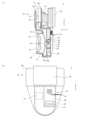
- FIG. 6 is a diagram showing an example of the sweat amount measuring device 2.
- FIG. 6A is a perspective cross-sectional view of the sweat amount measuring device 2 taken along a plane including the rotation axis AX of the fan 30 and the longitudinal direction of the sweat amount measuring device 2.
- FIG. 6(b) is a front view of the sweat amount measuring device 2 when the sweat amount measuring device 2 of FIG. 6(a) is viewed along arrow P.
- Reference numeral 80 indicates a battery.
- the battery 80 is supported and fixed by a battery support member 82 to the clip outer peripheral member 92b and the casing (no reference numeral).
- hardware constituting the control unit 70 is housed inside the casing (no reference numeral).
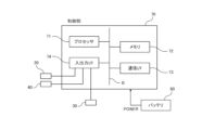
- FIG. 7 is a block diagram showing an example of an electrical hardware configuration implemented in the sweat amount measuring devices 1, 2, etc.
- the sweat amount measuring device 2 of the example (the sweat amount measuring device 1 according to Embodiment 1, the sweat amount measuring device 2 according to Embodiment 2, the sweat amount measuring device 3 according to each modification example described below) , 4, and 5) are electrically configured centering on the control section 70.
- the control unit 70 is a computer, and includes a processor 71, a memory 72 (storage not shown is also included in the concept of memory), a communication I/F (interface) 73, and an input/output I/F (interface) 74. These are connected to bus B. Battery 80 supplies power to control unit 70 .
- the processor 71 operates based on a program stored in the memory 72 and controls each part.
- the memory 72 also includes a nonvolatile storage device (ROM, etc.), and stores a boot program executed by the processor 71 when the sweat amount measuring device 2 is started, a program depending on the hardware of the control unit 70, etc. is stored.
- the communication I/F 73 transmits and receives data to and from an external management device (not shown) via a wireless communication means (no code).
- the input/output I/F 74 is electrically connected to the first temperature/humidity sensor 20, the second temperature/humidity sensor 40, the fan 30, etc., and interfaces with these input/output devices.
- the processor 71 controls the rotation of the fan 30.
- the processor 71 calculates the head sweat amount Y based on information from the first temperature/humidity sensor 20 and the second temperature/humidity sensor 40 transmitted via the input/output I/F 74. Further, the processor may calculate the whole body sweat amount based on the calculated head sweat amount Y.
- the processor 71 controls data transmission and reception with a management device (not shown) via the communication I/F 73.
- the processor 71 can also operate to hold data regarding the calculated head sweat amount Y and the whole body sweat amount in the memory 72.
- the control unit 70 calculates the moisture amount per unit volume as the inflow moisture amount X 1 based on the temperature t 1 and relative humidity RH 1 of the outside air OA received from the first temperature/humidity sensor 20 .
- the amount of inflow moisture is X 1 [g/m 3 ]
- the temperature of outside air OA is t 1 [°C]
- the relative humidity of outside air OA is RH 1 [%]
- the saturated water vapor pressure of outside air OA is e 1 [hPa].
- control unit 70 calculates the inflow water amount X 1 using the following equations (1) and (2).
- subscript 1 is picked up and applied to any one of the terms e, t, RH, and X in the following equations (1) to (3)
- subscript 1 is also applied to the other terms. shall be picked up and applied.
- subscript 2 is picked up and applied to one term, subscript 2 is also picked up and applied to other terms.
- control unit 70 controls the amount of moisture per unit volume as the outflow moisture amount Calculate quantities. Specifically, the amount of water flowing out is X 2 [g/m 3 ], the temperature of the internal air IA is t 2 [°C], the relative humidity of the internal air IA is RH 2 [%], and the saturated water vapor pressure of the internal air IA is Assuming e 2 [hPa], calculations are performed using the above formulas (1) and (2) to obtain the outflow water amount X 2 .
- the control unit 70 controls the inflow moisture amount X 1 [g/m 3 ], the outflow moisture amount X 2 [g/m 3 ], and the given (known) air flow rate F [m 3 ] of the fan 30 obtained by the above calculation. /min], the following formula (3) is used to calculate the head perspiration amount Y [g/m 3 ].
- control unit 70 can also estimate the whole body sweat amount based on the obtained head sweat amount Y.
- the control section 70 includes an "inflow moisture amount calculation section” that calculates the moisture amount per unit volume as the inflow moisture amount X1 , and an “outflow moisture amount calculation section” that calculates the moisture amount per unit volume as the outflow moisture amount X2 .
- a "head sweat amount calculation section” that calculates the head sweat amount Y based on the inflow moisture amount X 1 , the outflow moisture amount X 2 , and the air volume F related to the exhaust of the internal air IA by the fan 30.
- the control section may include a "whole body sweat amount calculation section” that estimates the whole body sweat amount based on the calculated head sweat amount Y.
- control section 70 within the sweat amount measuring device may include all of the above-mentioned inflow moisture amount calculation section, outflow moisture amount calculation section, head sweat amount calculation section, and whole body sweat amount calculation section,
- a management device other than the sweat amount measuring device may include part or all of the sweat amount measuring device.
- a sweat amount measuring system 9 can be configured by combining the sweat amount measuring device 1 according to Embodiment 1 and the helmet 100 (Embodiment 3).
- the sweat amount measuring system 9 includes a helmet 100 and the sweat amount measuring device 1 according to the first embodiment attached to the edge 102 of the helmet 100.
- the helmet 100 may be a commercially available general helmet, such as a work helmet commonly used in the construction industry.
- the helmet 100 includes an outer shell 101, an intermediate covering member 103, a collar 104, and the like.
- the outer shell 101 is a member that separates the outside world E from the head H of the wearer WR, and protects the head H from the outside world E.
- An in-helmet air flow path 110 is formed between the outer shell 101 and the head H of the wearer WR.
- the intermediate covering member 103 is, for example, an inner belt, and supports the helmet 100 while bringing the helmet 100 into contact with the head.
- the intermediate covering member 103 is open, allowing water vapor and hot air to pass between the head H and the helmet air flow path 110.
- the sweat amount measuring system 9 since the sweat amount measuring device 1 according to the first embodiment is used as the sweat amount measuring device, the effect that the sweat amount measuring device 1 according to the first embodiment has The same effect can be obtained. If such a sweat amount measuring system 9 is used, the amount of sweat on the head can be measured more accurately, and more accurate measures against heatstroke can be taken.
- a mode of configuring the sweat amount measurement system 9 using the sweat amount measurement device 1 according to the first embodiment has been described.
- the present invention is not limited to this, and a sweat amount measurement system using the sweat amount measurement device 2 according to the second embodiment (see FIG. 4) and the sweat amount measurement devices 3, 4, and 5 according to each modification example described later. can also be configured.
- FIG. 8 is a front view showing sensor covers 50' and 50'' of Modifications 1 and 2, respectively.
- FIG. 9 is a schematic cross-sectional view showing a sweat amount measuring device 3 according to a third modification.
- FIG. 10 is a schematic cross-sectional view showing a sweat amount measuring device 4 according to a fourth modification.
- FIG. 11 is a schematic cross-sectional view showing a sweat amount measuring device 5 according to a fifth modification.
- Embodiment 1 has been described using an example in which the slit-shaped outside air intake port 52 is provided on the front side of the sensor cover 50 (see FIG. 2).
- the present invention is not limited thereto.
- a plurality of openings may be provided on the side surface of the sensor cover 50', and these openings may be configured as the outside air intake port 52 (Modification 1).
- the front side of the sensor cover 50'' is shaped like a lattice (blind shape, mesh shape, etc. are also possible) so that outside air OA can freely pass through, and the first temperature and humidity are adjusted.
- the sensor 20 can also be configured to be protected from radiation from the outside world E (Modification 2).
- outside air intake port 52 is provided in the sensor cover 50, so that outside air OA flows in a natural manner.
- the present invention is not limited thereto.
- the sensor fan 58 can be actively used in the space 60 where outside air OA flows.
- a flow of outside air OA may be generated (Modification 3).
- the shielding member 94 partitioning member 94 that separates the air flow path 10 from the space 60 where the flow of outside air OA occurs is extended to the area where it touches the fan 30. It is also possible to extend the fan suction port 31 and actively generate a flow of outside air OA by the suction force from a part of the fan suction port 31 (Modification 4).
- the second temperature/humidity sensor 40 has been described using an example (see FIG. 1) in which the second temperature/humidity sensor 40 is disposed within the closed portion 96 of the air flow path 10.
- the present invention is not limited thereto.
- the second temperature/humidity sensor 40 may be placed outside the air flow path 10 so as to be in contact with the fan outlet 32 (Modification 5).
- the second temperature/humidity sensor 40 is arranged outside the fan 30, but even in such a case, the second temperature/humidity sensor 40 is "disposed midway through the flow of internal intake air.” be handled.
- the clip portion 92 was introduced as a helmet attachment means.
- the present invention is not limited thereto.
- the clip outer peripheral material 92b and the outer periphery of the edge of the helmet 100 may be tightened together with a belt (not shown) or the like to strengthen the fixation.
- the sweat amount measuring device may be placed between the belt and the outer shell 101 of the helmet 100 using only a belt, and the helmet 100 may be wrapped around the sweat amount measuring device and the belt.
- the outer shell 101 of the helmet 100 and the sweat amount measuring device may be attached by adhesively fixing them, for example, with an adhesive.
- the sweat amount measuring systems 9 and 9' in each embodiment and each modification are those in which the helmet 100 and the sweat amount measuring devices 1 to 5 are separate bodies, and are defined as sweat amount measuring systems 9 in a narrow sense. , 9' and explained.
- the present invention is not limited thereto.
- a dedicated helmet in which the helmet 100 and the sweat rate measuring devices 1 to 5 are integrated is also treated as equivalent to the sweat rate measuring system 9, 9', and is included in the sweat rate measuring system 9, 9' of the present invention. It will be done.
Landscapes
- Health & Medical Sciences (AREA)
- Life Sciences & Earth Sciences (AREA)
- Physics & Mathematics (AREA)
- Medical Informatics (AREA)
- Surgery (AREA)
- Engineering & Computer Science (AREA)
- Biomedical Technology (AREA)
- Heart & Thoracic Surgery (AREA)
- Biophysics (AREA)
- Molecular Biology (AREA)
- Pathology (AREA)
- Animal Behavior & Ethology (AREA)
- General Health & Medical Sciences (AREA)
- Public Health (AREA)
- Veterinary Medicine (AREA)
- Optics & Photonics (AREA)
- Measuring And Recording Apparatus For Diagnosis (AREA)
- Helmets And Other Head Coverings (AREA)
Abstract
Description
作業者の行動下での発汗量をリアルタイムで把握し、特に全身からの発汗量(全身発汗量)を把握して水分補給、作業中止等の対策を講じられれば有効であると考えられる。しかしながら、一般に全身発汗量を計測するには大掛かりな設備が必要となるため、このような設備を必要とする発汗量計測は建設業等の現場に適さない(例えば非特許文献1参照)。
非特許文献2及び特許文献1に記載された技術は、ファン付きの特定のヘルメットで成立する計測方式である。しかし、建設業等の現場では、様々なメーカーによるヘルメットが使用されており、ファン付きの特定のヘルメットを前提とした発汗量計測は普及しづらい。以上のように、建設業等の現場では、ファンが付いていない一般的なヘルメットに対しても広く取り付けられ、頭部発汗量をより正確に計測できる発汗量計測装置が要請されている。
発汗量計測装置は、頭部から発せられた水蒸気を含む空気(以下、「内空気」という。)が流れる空気流路と、外界に開放された場所に配置され、空気流路からみて装着者の側とは反対の側の場所から取り入れられた外界の空気(以下、「外空気」という。)の温度及び相対湿度を計測する第1温湿度センサと、空気流路内の内空気を吸引して、内空気を当該発汗量計測装置の外部に排出するファンと、ファンが動作することによって生じる内空気の流れの中途に配置され、内空気の温度及び相対湿度を計測する第2温湿度センサと、を備える。
1.実施形態1に係る発汗量計測装置1の構成
図1は、実施形態1に係る発汗量計測装置1及び実施形態3に係る発汗量計測システム9を示す模式的な断面図である。図においてIA,OAで示される矢印は当該空間に流れる内空気IA及び外空気OAの一部を例示的に説明するためのものである。ここでの矢印の方向は空気が進行する方向を示す(以下の図面においても同様)。図2は、図1の発汗量計測装置1を矢印Pに沿って視たときのセンサカバー50のみを示す正面図である。
図1に示すように、実施形態1に係る発汗量計測装置1はヘルメット100の縁部102に取り付けられ、該ヘルメット100の装着者WRの頭部Hからの発汗量を計測する装置である。
空気流路10は、装着者WRの頭部Hから発せられた水蒸気を含む空気(内空気IA)が流れる構造部である。空気流路10は、クリップ内周材92a及びクリップ外周材92b、後述する閉塞部96における内壁96b及び底96a、後述する遮蔽部材94等のそれぞれの壁によって囲まれて構成されている。
空気流路10は、クリップ内周材92a及びクリップ外周材92bのそれぞれの一端によって構成される開口部12を有している。開口部12から閉塞部96の内側まで繋がった空間は空気流路10を構成する。開口部12は、ヘルメット100と頭部Hとの間の空間であるヘルメット内空気流路110に接続され、かかる開口部12から内空気IAを取り込めるようになっている。
第1温湿度センサ20は、外空気OAの単位体積当たりに含まれる水分量X(絶対湿度Xということもある)を計測するためのセンサである。第1温湿度センサ20は、外界Eに開放された場所に配置され、空気流路10からみて装着者WRの側とは反対の側の場所から取り入れられた外界Eの空気(外空気OA)の温度及び相対湿度を計測する。第1温湿度センサ20は、有線又は無線により制御部70と電気的に接続されており(図7参照)、センシングした計測値を制御部70に伝える。
第1温湿度センサ20は外界Eに露出した状態となっていてもよい。発汗量計測装置1を屋内で使用する場合でセンサカバー50が不要な場合には、カバー無しとすることで発汗量計測装置1の構造を簡便化し、発汗量計測装置1を軽量化することができる。
ただ、第1温湿度センサ20は、特に太陽光線など外部からの輻射熱の影響を第1温湿度センサ20が受けにくいように、更にセンサカバー50で覆われていることが好ましい。図1及び図2で示す例では、発汗量計測装置1には第1温湿度センサ20を覆うセンサカバー50が設けられている。
第1温湿度センサ20は、空間的には外空気取入れ口52及び外空気取出し口53を介して外界Eに通じており、外界に開放された場所に配置されている。
なお、発汗量計測装置1は、センサカバー50に外空気取出し口53を有さず外空気取入れ口52のみを有する構成としても構わない。
ファン30は、空気流路10やヘルメット内空気流路110でなる空間系に存在する空気を強制的に流動させる。ファン30は空気流路10に隣接して配置されている。
ファン30は、制御部70と電気的に接続されており(図7参照)、制御部70から供給された駆動信号又は駆動電力により空気を空気流路10の内から外(当該発汗量計測装置1の外部)に送る方向に回転制御される。このように制御されると、ファン30は、空気流路10内の内空気IAを吸引して、該内空気IAを当該発汗量計測装置1の外部に排出する。このとき、空気流路10やヘルメット内空気流路110には陰圧が生じる。
第2温湿度センサ40は、内空気IAの単位体積当たりに含まれる水分量X2(絶対湿度X2ということもある)を計測するためのセンサである。
第2温湿度センサ40は、ファン30が動作することによって生じる内空気IAの流れの中途に配置され、内空気IAの温度及び相対湿度を計測する。第2温湿度センサ40は、有線又は無線により制御部70と電気的に接続されており(図7参照)、センシングした計測値を制御部70に伝える。
空気流路10は、ファン30に隣接して形成された閉塞部96を有している。空気流路10の全体的な形状は、開口部12を「入口」としたときに閉塞部96の末端付近(閉塞部96の底96a)で「行き止まり」となった、いわゆる袋小路状となっている。
このとき、ファン30は空気流路10の閉塞部96の末端付近において空気流路10の長手方向に平行に隣接して配置されている。ファン30を動作させると、空気流路10を流れる内空気IAは閉塞部96の末端付近からファン30で排出される。ファン30が動作すると空気流路10にはファン30を源とする陰圧が生じ、内空気IAの多くの部分が閉塞部96内の末端付近(袋小路の袋の底付近)やファン近傍に集まって通過することとなる。
発汗量計測装置1は、基本的には非特許文献2に記載された発汗量計測の原理を用いて頭部発汗量Yを計測することができる。ただし、実施形態1ではこれに限定されるものではない。
更に、算定した頭部発汗量Yに基づいて全身発汗量を推定することができる。
なお、頭部発汗量Yの算定に関する詳細については後の[実施例]で触れる。
発明者らは、シミュレーションにより、頭部発汗量を正確に計測するために適した第1温湿度センサ20の配置位置について新たな知見を得たので、以下説明する。
ヘルメット本体とヘルメット内空気を排気するファンが付加されたヘルメットを人間が装着したものとする。ヘルメットの内側からは平均的な人間が装着した場合と同等の水蒸気発生・熱発生があるものとし、装着者(ヘルメットを装着した人間)からは単位時間当たり一定量の発汗があるものと設定する。ヘルメットの後方から速度1.5[m/s]の風が当たったものとする。
頭部発汗量(相当量)Yを算定する原理としては、非特許文献2に記載された発汗量計測の原理を用いる。
第1温湿度センサについては、第1水準として、ヘルメット内空気流路又は空気流路からみて装着者の側とは反対の側の場所に配置する。具体的には、ヘルメットの外殻の外側に配置するものと仮定する。また、第2水準として、ヘルメット内部であって外空気の流入口付近に第1温湿度センサを配置する(非特許文献2のFig.1を参照)。
図3は、第1温湿度センサ20の配置場所を異ならせて水準を変えながら、頭部発汗量相当量の積算量をシミュレーションで算出しプロットしたグラフである。
図3のグラフに示すように、水準1では、時間の経過と共に頭部発汗量相当量(積算)はリニアに上昇していた。一方で、水準2では、時間の経過と共に頭部発汗量相当量(積算値)は上昇する傾向にあるものの、ある時間を過ぎると積算値は飽和していた。
他方、水準1のグラフでは、時間の経過と共に頭部発汗量相当量(積算)はリニアに上昇しており、水準1の第1温湿度センサの配置位置によれば、実際の頭部発汗量により近い値を得られることが分かった。
以上のシミュレーション結果から、発汗量計測装置1を構成するに当たっては、水準1に倣って、第1温湿度センサをヘルメット内空気流路又は空気流路からみて装着者の側とは反対の側の場所に配置することが好ましいことが確認された。
(1)非特許文献2に記載された発汗量計測装置においては、流入空気側の温湿度センサ(第1温湿度センサ20に対応する)がヘルメットの内縁辺りに配置されている。かかるセンサの配置位置は外界の空気が取り込まれる位置であるとはいえ、かかる位置から装着者の首、額、胸、背中等から発する熱や水分も併せて混入する可能性がある。こうしたことから、非特許文献2に記載された発汗量計測装置の構成では、装着者の熱や水分の影響を受ける可能性があり、より正確に頭部発汗量を計測する上で改善の余地がある。
また、第1温湿度センサ20は、外空気OAの流れが生じる空間に配置されている。第1温湿度センサ20を、単に外空気OAに接するだけでなく外空気OAの流れのある空間に配置することにより、第1温湿度センサ20には、人体からの発汗は発熱の影響を受けない新鮮な外空気OAが常に当たることとなる。このため、頭部発汗量Yをより正確に計測することができる。
このような構成となっているため、空気流路10にはファン30を源とする陰圧が生じ、内空気IAの多くの部分を閉塞部96内の末端付近(袋小路の袋の底付近)やファン30近傍に集めて通過させることができる。また、閉塞部96内では新たな外空気OAは混ざりづらくなっている。このように閉塞部96の末端付近やファン30近傍に集まった純度の高い内空気IAを第2温湿度センサ40で安定的にセンシングできることから、より正確で高精度な発汗量計測を行うことができる。
図4は、実施形態2に係る発汗量計測装置2及び実施形態3に係る発汗量計測システム9’を示す模式的な断面図である。図5は、図4の発汗量計測装置4を矢印Pに沿って視たときのセンサカバー50のみを示す正面図である。
図4及び図5に示すように、実施形態2に係る発汗量計測装置2は、空気流路10と第1温湿度センサ20が配置された空間との間には連通部95を有する遮蔽部材94が備えられている。遮蔽部材94は、空気流路10と外空気OAの流れが生じる空間60とを区画することから「区画部材94」と言い換えることができる。
実施例の発汗量計測装置2は、これまで図4を用いて説明してきた実施形態2に係る発汗量計測装置2と基本的に同様となっているため、実施形態2に係る発汗量計測装置2と共通する構成要件の説明は、ここで援用し、改めての説明は省略する。
バッテリ80は、制御部70に対し電源を供給する。
を行う。メモリ72の中には不揮発性の記憶デバイス(ROM等)も含まれており、発汗量計測装置2の起動時にプロセッサ71によって実行されるブートプログラムや、制御部70のハードウェアに依存するプログラム等が格納される。
入出力I/F74は、第1温湿度センサ20、第2温湿度センサ40、ファン30などとそれぞれ電気的に接続されており、これらの入出力デバイスとのインターフェースを行う。
プロセッサ71はファン30の回転制御を行う。プロセッサ71は、入出力I/F74を介して伝えられた第1温湿度センサ20及び第2温湿度センサ40からの情報に基づいて頭部発汗量Yを演算する。また、プロセッサは算出された頭部発汗量Yに基づいて全身発汗量を算出してもよい。プロセッサ71は、通信I/F73を介して管理装置(図示を省略)との間のデータ送受信の制御を行う。プロセッサ71は、算出された頭部発汗量Yや全身発汗量に関するデータをメモリ72で保持するよう動作することも可能である。
相対湿度から単位体積当たりの水分量(絶対湿度)を推定するのには各種の近似式があるが、ここでは比較的よく用いられるTetensの式で推定することとする。
流入水分量をX1[g/m3]、外空気OAの温度をt1[℃]、外空気OAの相対湿度をRH1[%]、外空気OAの飽和水蒸気圧をe1[hPa]とした場合、制御部70は、下記式(1)及び式(2)により演算をし流入水分量X1を得る。
なお、以下の式(1)~(3)においてe、t、RH、Xの各項のいずれか1つの項で添え字1を拾って適用するときは、他の項においても添え字1を拾って適用するものとする。同様に1つの項で添え字2を拾って適用するときは、他の項においても添え字2を拾って適用する。

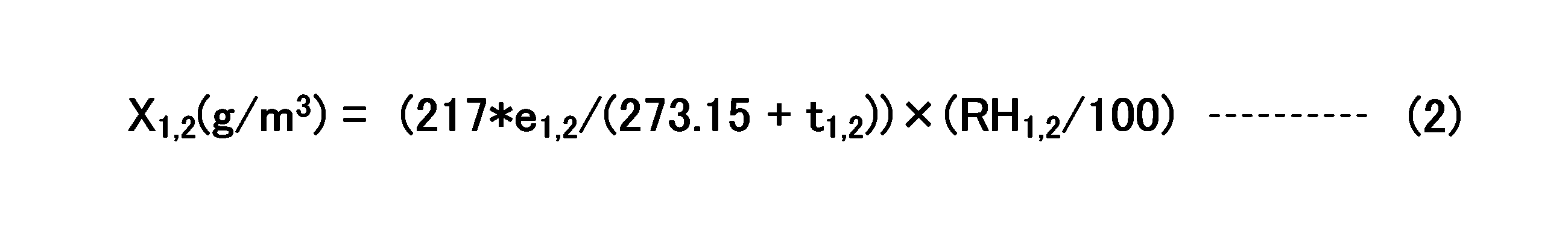

図1に戻って、実施形態1に係る発汗量計測装置1とヘルメット100とを組み合わせて発汗量計測システム9を構成することができる(実施形態3)。
発汗量計測システム9はヘルメット100と、ヘルメット100の縁部102に取り付けられた実施形態1に係る発汗量計測装置1とを備える。
ヘルメット100は、外殻101、中間被覆部材103、つば104等を有している。外殻101は、外界Eと装着者WRの頭部Hとの間を隔てる部材で、頭部Hを外界Eから保護する。外殻101と装着者WRの頭部Hとの間にはヘルメット内空気流路110が形成される。中間被覆部材103は、例えばインナー・ベルトなどであり、ヘルメット100を頭部に接触させつつヘルメット100を支持する。中間被覆部材103は開口しており、頭部Hとヘルメット内空気流路110との間で水蒸気や熱気が行き来可能となっている。
なお、図8は変形例1,2のセンサカバー50’,50’’をそれぞれ示す正面図である。図9は変形例3に係る発汗量計測装置3を示す模式的な断面図である。図10は変形例4に係る発汗量計測装置4を示す模式的な断面図である。図11は変形例5に係る発汗量計測装置5を示す模式的な断面図である。
例えば、クリップ部92による固定に加えて、図示しないベルト等でクリップ外周材92bとヘルメット100の縁部の外周とを共締めして固定を強化してもよい。また、ベルトのみを用いて、ベルトとヘルメット100の外殻101との間に発汗量計測装置を配置し、ベルトで発汗量計測装置と共にヘルメット100を巻き付けるようにしてもよい。また、例えば接着剤でヘルメット100の外殻101と発汗量計測装置とを接着固定して取り付けてもよい。
Claims (12)
- ヘルメットの縁部に取り付けられ、該ヘルメットの装着者の頭部からの発汗量を計測する発汗量計測装置であって、
前記頭部から発せられた水蒸気を含む空気である内空気が流れる空気流路と、
外界に開放された場所に配置され、前記空気流路からみて前記装着者の側とは反対の側の場所から取り入れられた前記外界の空気である外空気の温度及び相対湿度を計測する第1温湿度センサと、
前記空気流路内の前記内空気を吸引して、該内空気を当該発汗量計測装置の外部に排出するファンと、
前記ファンが動作することによって生じる前記内空気の流れの中途に配置され、前記内空気の温度及び相対湿度を計測する第2温湿度センサと、
を備えたことを特徴とする発汗量計測装置。 - 請求項1に記載の発汗量計測装置において、
前記第1温湿度センサを覆うセンサカバーが設けられている、
ことを特徴とする発汗量計測装置。 - 請求項2に記載の発汗量計測装置において、
前記センサカバーは、外気取入れ口及び外気取出し口を有する、
ことを特徴とする発汗量計測装置。 - 請求項3に記載の発汗量計測装置において、
前記第1温湿度センサは、前記外空気の流れが生じる空間に配置されている、
ことを特徴とする発汗量計測装置。 - 請求項4に記載の発汗量計測装置において、
前記空気流路と前記第1温湿度センサが配置された空間との間には連通部を有する遮蔽部材が備えられている、
ことを特徴とする発汗量計測装置。 - 請求項5に記載の発汗量計測装置において、
前記第1温湿度センサが配置された空間は、前記第1温湿度センサ付近において前記外空気が略一定の風量で流れるように構成されている、
ことを特徴とする発汗量計測装置。 - 請求項6に記載の発汗量計測装置において、
前記第1温湿度センサは、前記外空気の流れに着目したときに、前記連通部の上流であって前記連通部の近傍に配置されている、
ことを特徴とする発汗量計測装置。 - 請求項6に記載の発汗量計測装置において、
前記空気流路は、前記ファンに隣接して形成された閉塞部を有し、
前記第2温湿度センサは、前記ファンの近傍に配置されている、
ことを特徴とする発汗量計測装置。 - 請求項1又は2に記載の発汗量計測装置において、
前記空気流路は、前記ファンに隣接して形成された閉塞部を有し、
前記第2温湿度センサは、前記ファンの近傍に配置されている、
ことを特徴とする発汗量計測装置。 - 請求項1又は2に記載の発汗量計測装置において、
前記ファンが配置される位置は、前記発汗量計測装置が前記ヘルメットの縁部に取り付けられた状態において、前記ファンによる空気の排出先が前記装着者の後頭部から首筋の辺りとなるように設定されている、
ことを特徴とする発汗量計測装置。 - 請求項1又は2に記載の発汗量計測装置において、
前記発汗量計測装置は、
前記ヘルメットの外殻と前記装着者の前記頭部との間に形成される空間をヘルメット内空気流路と定義したときに、
前記ヘルメット内空気流路に流入する外界の空気の温度及び相対湿度を前記第1温湿度センサで計測して流入水分量としての単位体積当たりの水分量を算定し、
前記ヘルメット内空気流路で生じた前記内空気の温度及び相対湿度を前記第2温湿度センサで計測して流出水分量としての単位体積当たりの水分量を算定し、
前記流入水分量と前記流出水分量と前記ファンによる前記内空気の排気に係る風量とに基づき前記頭部からの発汗量である頭部発汗量を算定し、
算定した前記頭部発汗量に基づいて全身発汗量を推定する、ためのものである、
ことを特徴とする発汗量計測装置。 - 前記ヘルメットと、前記ヘルメットの縁部に取り付けられた請求項1又は2に記載の発汗量計測装置と、を備えた発汗量計測システム。
Priority Applications (4)
| Application Number | Priority Date | Filing Date | Title |
|---|---|---|---|
| JP2024514160A JP7734387B2 (ja) | 2022-04-08 | 2023-02-01 | 発汗量計測装置及び発汗量計測システム |
| US18/563,624 US20240268714A1 (en) | 2022-04-08 | 2023-02-01 | Perspiration amount measuring device and perspiration amount measuring system |
| EP23784514.4A EP4505896A4 (en) | 2022-04-08 | 2023-02-01 | DEVICE AND SYSTEM FOR MEASURING THE QUANTITY OF TRANSPIRATION |
| JP2025132416A JP2025170282A (ja) | 2022-04-08 | 2025-08-07 | 発汗量計測装置及び発汗量計測システム |
Applications Claiming Priority (2)
| Application Number | Priority Date | Filing Date | Title |
|---|---|---|---|
| JP2022-064656 | 2022-04-08 | ||
| JP2022064656 | 2022-04-08 |
Publications (1)
| Publication Number | Publication Date |
|---|---|
| WO2023195219A1 true WO2023195219A1 (ja) | 2023-10-12 |
Family
ID=88242775
Family Applications (1)
| Application Number | Title | Priority Date | Filing Date |
|---|---|---|---|
| PCT/JP2023/003207 Ceased WO2023195219A1 (ja) | 2022-04-08 | 2023-02-01 | 発汗量計測装置及び発汗量計測システム |
Country Status (4)
| Country | Link |
|---|---|
| US (1) | US20240268714A1 (ja) |
| EP (1) | EP4505896A4 (ja) |
| JP (2) | JP7734387B2 (ja) |
| WO (1) | WO2023195219A1 (ja) |
Families Citing this family (1)
| Publication number | Priority date | Publication date | Assignee | Title |
|---|---|---|---|---|
| US12336587B2 (en) * | 2023-01-30 | 2025-06-24 | Milwaukee Electric Tool Corporation | Hard hat with fan |
Citations (4)
| Publication number | Priority date | Publication date | Assignee | Title |
|---|---|---|---|---|
| JP2016132835A (ja) * | 2015-01-16 | 2016-07-25 | 株式会社タニタ | 測定装置および装着システム |
| JP2017153576A (ja) * | 2016-02-29 | 2017-09-07 | シャープ株式会社 | 発汗量検出装置 |
| WO2020184686A1 (ja) * | 2019-03-13 | 2020-09-17 | 公立大学法人公立諏訪東京理科大学 | 頭部装着装置、熱中症予防システム及び水分補給警告システム |
| JP2021135971A (ja) * | 2020-02-28 | 2021-09-13 | 公立大学法人公立諏訪東京理科大学 | 全身発汗量推定システム及び熱中症予防システム |
Family Cites Families (1)
| Publication number | Priority date | Publication date | Assignee | Title |
|---|---|---|---|---|
| CA2740738A1 (en) * | 2008-10-16 | 2010-04-22 | HaberVision LLC | Actively ventilated helmet systems and methods |
-
2023
- 2023-02-01 EP EP23784514.4A patent/EP4505896A4/en active Pending
- 2023-02-01 US US18/563,624 patent/US20240268714A1/en active Pending
- 2023-02-01 JP JP2024514160A patent/JP7734387B2/ja active Active
- 2023-02-01 WO PCT/JP2023/003207 patent/WO2023195219A1/ja not_active Ceased
-
2025
- 2025-08-07 JP JP2025132416A patent/JP2025170282A/ja active Pending
Patent Citations (4)
| Publication number | Priority date | Publication date | Assignee | Title |
|---|---|---|---|---|
| JP2016132835A (ja) * | 2015-01-16 | 2016-07-25 | 株式会社タニタ | 測定装置および装着システム |
| JP2017153576A (ja) * | 2016-02-29 | 2017-09-07 | シャープ株式会社 | 発汗量検出装置 |
| WO2020184686A1 (ja) * | 2019-03-13 | 2020-09-17 | 公立大学法人公立諏訪東京理科大学 | 頭部装着装置、熱中症予防システム及び水分補給警告システム |
| JP2021135971A (ja) * | 2020-02-28 | 2021-09-13 | 公立大学法人公立諏訪東京理科大学 | 全身発汗量推定システム及び熱中症予防システム |
Non-Patent Citations (3)
| Title |
|---|
| See also references of EP4505896A4 |
| SHINSUKE SAWASAKI: "Study on Thermal Evaluation Method for Hot Outdoor Environment", SEISAN KENKYU, vol. 58, 2006, pages 323 - 327 |
| TSUKASA KOSUDA: "Journal of Japan Institute of Electronics Packaging, General Incorporated Association", vol. 24, 2021, JAPAN INSTITUTE OF ELECTRONICS PACKAGING, article "Development of a Helmet Device Capable of Measuring Perspiration during Activity and Possibility of New Index for the Early Detection of Heat Stroke", pages: 541 - 550 |
Also Published As
| Publication number | Publication date |
|---|---|
| EP4505896A1 (en) | 2025-02-12 |
| US20240268714A1 (en) | 2024-08-15 |
| EP4505896A4 (en) | 2025-11-19 |
| JP7734387B2 (ja) | 2025-09-05 |
| JP2025170282A (ja) | 2025-11-18 |
| JPWO2023195219A1 (ja) | 2023-10-12 |
Similar Documents
| Publication | Publication Date | Title |
|---|---|---|
| EP3646684B1 (en) | Thermal regulation for head-mounted display | |
| JP2025170282A (ja) | 発汗量計測装置及び発汗量計測システム | |
| US11375950B2 (en) | Systems and methods for measuring respiratory biometrics | |
| CN113557556B (zh) | 头部佩戴装置、中暑预防系统以及水分补充警告系统 | |
| JP7222158B2 (ja) | 頭部装着装置、熱中症予防システム及び水分補給警告システム | |
| US20250311964A1 (en) | Perspiration amount measuring device and perspiration amount measuring system | |
| JP7495064B2 (ja) | 頭部装着装置、熱中症予防システム及び水分補給警告システム | |
| CN109165413A (zh) | 一种评价飞机座舱环境下乘客热舒适性的方法及系统 | |
| KR102077403B1 (ko) | 쿨링시스템 옷 | |
| EP4417888A1 (en) | Air conditioning system, information processing device, and air conditioner control method | |
| JPWO2024185648A5 (ja) | ||
| JP7411948B2 (ja) | 衣服、熱中症予防システム及び水分補給警告システム | |
| US20240116329A1 (en) | Thermal sensation estimation device, air conditioning device, air conditioning system, thermal sensation estimation method, and program | |
| JP7432204B2 (ja) | 全身発汗量推定システム及び熱中症予防システム | |
| Patrick Morrissey et al. | The influence of fabric air permeability on the efficacy of ventilation features | |
| JP2025170282A5 (ja) | ||
| JP7417932B2 (ja) | 全身発汗量推定システム及び熱中症予防システム | |
| KR20210046894A (ko) | 냉각 및 방풍과 근골격계 보존을 위한 기능성 작업복 | |
| JP7417933B2 (ja) | 熱中症予防システム | |
| ES2991254T3 (es) | Dispositivo sensor portátil y sistema de monitorización | |
| WO2020184688A1 (ja) | 頭部装着装置、熱中症予防システム及び水分補給警告システム | |
| KR102732653B1 (ko) | 체온조절용 슈트 | |
| CN212065741U (zh) | 一种可控温湿度的衣内腰环 | |
| KR20220086163A (ko) | 공조복 | |
| US20230048877A1 (en) | Method, apparatus for temperature detection and wearable device |
Legal Events
| Date | Code | Title | Description |
|---|---|---|---|
| 121 | Ep: the epo has been informed by wipo that ep was designated in this application |
Ref document number: 23784514 Country of ref document: EP Kind code of ref document: A1 |
|
| WWE | Wipo information: entry into national phase |
Ref document number: 18563624 Country of ref document: US |
|
| WWE | Wipo information: entry into national phase |
Ref document number: 2024514160 Country of ref document: JP |
|
| WWE | Wipo information: entry into national phase |
Ref document number: 2023784514 Country of ref document: EP |
|
| NENP | Non-entry into the national phase |
Ref country code: DE |
|
| ENP | Entry into the national phase |
Ref document number: 2023784514 Country of ref document: EP Effective date: 20241108 |