WO2023195548A1 - 電池制御装置および電池システム - Google Patents
電池制御装置および電池システム Download PDFInfo
- Publication number
- WO2023195548A1 WO2023195548A1 PCT/JP2023/016036 JP2023016036W WO2023195548A1 WO 2023195548 A1 WO2023195548 A1 WO 2023195548A1 JP 2023016036 W JP2023016036 W JP 2023016036W WO 2023195548 A1 WO2023195548 A1 WO 2023195548A1
- Authority
- WO
- WIPO (PCT)
- Prior art keywords
- input
- soc
- battery
- voltage
- power
- Prior art date
- Legal status (The legal status is an assumption and is not a legal conclusion. Google has not performed a legal analysis and makes no representation as to the accuracy of the status listed.)
- Ceased
Links
Images







Classifications
-
- H—ELECTRICITY
- H02—GENERATION; CONVERSION OR DISTRIBUTION OF ELECTRIC POWER
- H02J—ELECTRIC POWER NETWORKS; CIRCUIT ARRANGEMENTS OR SYSTEMS FOR SUPPLYING OR DISTRIBUTING ELECTRIC POWER; SYSTEMS FOR STORING ELECTRIC ENERGY
- H02J7/00—Circuit arrangements for charging or discharging batteries or for supplying loads from batteries
- H02J7/90—Regulation of charging or discharging current or voltage
- H02J7/96—Regulation of charging or discharging current or voltage in response to battery voltage
-
- B—PERFORMING OPERATIONS; TRANSPORTING
- B60—VEHICLES IN GENERAL
- B60L—PROPULSION OF ELECTRICALLY-PROPELLED VEHICLES; SUPPLYING ELECTRIC POWER FOR AUXILIARY EQUIPMENT OF ELECTRICALLY-PROPELLED VEHICLES; ELECTRODYNAMIC BRAKE SYSTEMS FOR VEHICLES IN GENERAL; MAGNETIC SUSPENSION OR LEVITATION FOR VEHICLES; MONITORING OPERATING VARIABLES OF ELECTRICALLY-PROPELLED VEHICLES; ELECTRIC SAFETY DEVICES FOR ELECTRICALLY-PROPELLED VEHICLES
- B60L3/00—Electric devices on electrically-propelled vehicles for safety purposes; Monitoring operating variables, e.g. speed, deceleration or energy consumption
- B60L3/12—Recording operating variables ; Monitoring of operating variables
-
- B—PERFORMING OPERATIONS; TRANSPORTING
- B60—VEHICLES IN GENERAL
- B60L—PROPULSION OF ELECTRICALLY-PROPELLED VEHICLES; SUPPLYING ELECTRIC POWER FOR AUXILIARY EQUIPMENT OF ELECTRICALLY-PROPELLED VEHICLES; ELECTRODYNAMIC BRAKE SYSTEMS FOR VEHICLES IN GENERAL; MAGNETIC SUSPENSION OR LEVITATION FOR VEHICLES; MONITORING OPERATING VARIABLES OF ELECTRICALLY-PROPELLED VEHICLES; ELECTRIC SAFETY DEVICES FOR ELECTRICALLY-PROPELLED VEHICLES
- B60L58/00—Methods or circuit arrangements for monitoring or controlling batteries or fuel cells, specially adapted for electric vehicles
- B60L58/10—Methods or circuit arrangements for monitoring or controlling batteries or fuel cells, specially adapted for electric vehicles for monitoring or controlling batteries
- B60L58/12—Methods or circuit arrangements for monitoring or controlling batteries or fuel cells, specially adapted for electric vehicles for monitoring or controlling batteries responding to state of charge [SoC]
-
- B—PERFORMING OPERATIONS; TRANSPORTING
- B60—VEHICLES IN GENERAL
- B60L—PROPULSION OF ELECTRICALLY-PROPELLED VEHICLES; SUPPLYING ELECTRIC POWER FOR AUXILIARY EQUIPMENT OF ELECTRICALLY-PROPELLED VEHICLES; ELECTRODYNAMIC BRAKE SYSTEMS FOR VEHICLES IN GENERAL; MAGNETIC SUSPENSION OR LEVITATION FOR VEHICLES; MONITORING OPERATING VARIABLES OF ELECTRICALLY-PROPELLED VEHICLES; ELECTRIC SAFETY DEVICES FOR ELECTRICALLY-PROPELLED VEHICLES
- B60L58/00—Methods or circuit arrangements for monitoring or controlling batteries or fuel cells, specially adapted for electric vehicles
- B60L58/10—Methods or circuit arrangements for monitoring or controlling batteries or fuel cells, specially adapted for electric vehicles for monitoring or controlling batteries
- B60L58/12—Methods or circuit arrangements for monitoring or controlling batteries or fuel cells, specially adapted for electric vehicles for monitoring or controlling batteries responding to state of charge [SoC]
- B60L58/13—Maintaining the SoC within a determined range
-
- B—PERFORMING OPERATIONS; TRANSPORTING
- B60—VEHICLES IN GENERAL
- B60L—PROPULSION OF ELECTRICALLY-PROPELLED VEHICLES; SUPPLYING ELECTRIC POWER FOR AUXILIARY EQUIPMENT OF ELECTRICALLY-PROPELLED VEHICLES; ELECTRODYNAMIC BRAKE SYSTEMS FOR VEHICLES IN GENERAL; MAGNETIC SUSPENSION OR LEVITATION FOR VEHICLES; MONITORING OPERATING VARIABLES OF ELECTRICALLY-PROPELLED VEHICLES; ELECTRIC SAFETY DEVICES FOR ELECTRICALLY-PROPELLED VEHICLES
- B60L58/00—Methods or circuit arrangements for monitoring or controlling batteries or fuel cells, specially adapted for electric vehicles
- B60L58/10—Methods or circuit arrangements for monitoring or controlling batteries or fuel cells, specially adapted for electric vehicles for monitoring or controlling batteries
- B60L58/12—Methods or circuit arrangements for monitoring or controlling batteries or fuel cells, specially adapted for electric vehicles for monitoring or controlling batteries responding to state of charge [SoC]
- B60L58/14—Preventing excessive discharging
-
- B—PERFORMING OPERATIONS; TRANSPORTING
- B60—VEHICLES IN GENERAL
- B60L—PROPULSION OF ELECTRICALLY-PROPELLED VEHICLES; SUPPLYING ELECTRIC POWER FOR AUXILIARY EQUIPMENT OF ELECTRICALLY-PROPELLED VEHICLES; ELECTRODYNAMIC BRAKE SYSTEMS FOR VEHICLES IN GENERAL; MAGNETIC SUSPENSION OR LEVITATION FOR VEHICLES; MONITORING OPERATING VARIABLES OF ELECTRICALLY-PROPELLED VEHICLES; ELECTRIC SAFETY DEVICES FOR ELECTRICALLY-PROPELLED VEHICLES
- B60L58/00—Methods or circuit arrangements for monitoring or controlling batteries or fuel cells, specially adapted for electric vehicles
- B60L58/10—Methods or circuit arrangements for monitoring or controlling batteries or fuel cells, specially adapted for electric vehicles for monitoring or controlling batteries
- B60L58/12—Methods or circuit arrangements for monitoring or controlling batteries or fuel cells, specially adapted for electric vehicles for monitoring or controlling batteries responding to state of charge [SoC]
- B60L58/15—Preventing overcharging
-
- B—PERFORMING OPERATIONS; TRANSPORTING
- B60—VEHICLES IN GENERAL
- B60L—PROPULSION OF ELECTRICALLY-PROPELLED VEHICLES; SUPPLYING ELECTRIC POWER FOR AUXILIARY EQUIPMENT OF ELECTRICALLY-PROPELLED VEHICLES; ELECTRODYNAMIC BRAKE SYSTEMS FOR VEHICLES IN GENERAL; MAGNETIC SUSPENSION OR LEVITATION FOR VEHICLES; MONITORING OPERATING VARIABLES OF ELECTRICALLY-PROPELLED VEHICLES; ELECTRIC SAFETY DEVICES FOR ELECTRICALLY-PROPELLED VEHICLES
- B60L58/00—Methods or circuit arrangements for monitoring or controlling batteries or fuel cells, specially adapted for electric vehicles
- B60L58/10—Methods or circuit arrangements for monitoring or controlling batteries or fuel cells, specially adapted for electric vehicles for monitoring or controlling batteries
- B60L58/16—Methods or circuit arrangements for monitoring or controlling batteries or fuel cells, specially adapted for electric vehicles for monitoring or controlling batteries responding to battery ageing, e.g. to the number of charging cycles or the state of health [SoH]
-
- B—PERFORMING OPERATIONS; TRANSPORTING
- B60—VEHICLES IN GENERAL
- B60L—PROPULSION OF ELECTRICALLY-PROPELLED VEHICLES; SUPPLYING ELECTRIC POWER FOR AUXILIARY EQUIPMENT OF ELECTRICALLY-PROPELLED VEHICLES; ELECTRODYNAMIC BRAKE SYSTEMS FOR VEHICLES IN GENERAL; MAGNETIC SUSPENSION OR LEVITATION FOR VEHICLES; MONITORING OPERATING VARIABLES OF ELECTRICALLY-PROPELLED VEHICLES; ELECTRIC SAFETY DEVICES FOR ELECTRICALLY-PROPELLED VEHICLES
- B60L58/00—Methods or circuit arrangements for monitoring or controlling batteries or fuel cells, specially adapted for electric vehicles
- B60L58/10—Methods or circuit arrangements for monitoring or controlling batteries or fuel cells, specially adapted for electric vehicles for monitoring or controlling batteries
- B60L58/18—Methods or circuit arrangements for monitoring or controlling batteries or fuel cells, specially adapted for electric vehicles for monitoring or controlling batteries of two or more battery modules
- B60L58/21—Methods or circuit arrangements for monitoring or controlling batteries or fuel cells, specially adapted for electric vehicles for monitoring or controlling batteries of two or more battery modules having the same nominal voltage
-
- H—ELECTRICITY
- H01—ELECTRIC ELEMENTS
- H01M—PROCESSES OR MEANS, e.g. BATTERIES, FOR THE DIRECT CONVERSION OF CHEMICAL ENERGY INTO ELECTRICAL ENERGY
- H01M10/00—Secondary cells; Manufacture thereof
- H01M10/42—Methods or arrangements for servicing or maintenance of secondary cells or secondary half-cells
- H01M10/425—Structural combination with electronic components, e.g. electronic circuits integrated to the outside of the casing
-
- H—ELECTRICITY
- H01—ELECTRIC ELEMENTS
- H01M—PROCESSES OR MEANS, e.g. BATTERIES, FOR THE DIRECT CONVERSION OF CHEMICAL ENERGY INTO ELECTRICAL ENERGY
- H01M10/00—Secondary cells; Manufacture thereof
- H01M10/42—Methods or arrangements for servicing or maintenance of secondary cells or secondary half-cells
- H01M10/44—Methods for charging or discharging
- H01M10/443—Methods for charging or discharging in response to temperature
-
- H—ELECTRICITY
- H01—ELECTRIC ELEMENTS
- H01M—PROCESSES OR MEANS, e.g. BATTERIES, FOR THE DIRECT CONVERSION OF CHEMICAL ENERGY INTO ELECTRICAL ENERGY
- H01M10/00—Secondary cells; Manufacture thereof
- H01M10/42—Methods or arrangements for servicing or maintenance of secondary cells or secondary half-cells
- H01M10/48—Accumulators combined with arrangements for measuring, testing or indicating the condition of cells, e.g. the level or density of the electrolyte
- H01M10/482—Accumulators combined with arrangements for measuring, testing or indicating the condition of cells, e.g. the level or density of the electrolyte for several batteries or cells simultaneously or sequentially
-
- H—ELECTRICITY
- H02—GENERATION; CONVERSION OR DISTRIBUTION OF ELECTRIC POWER
- H02J—ELECTRIC POWER NETWORKS; CIRCUIT ARRANGEMENTS OR SYSTEMS FOR SUPPLYING OR DISTRIBUTING ELECTRIC POWER; SYSTEMS FOR STORING ELECTRIC ENERGY
- H02J7/00—Circuit arrangements for charging or discharging batteries or for supplying loads from batteries
- H02J7/50—Circuit arrangements for charging or discharging batteries or for supplying loads from batteries acting upon multiple batteries simultaneously or sequentially
-
- H—ELECTRICITY
- H02—GENERATION; CONVERSION OR DISTRIBUTION OF ELECTRIC POWER
- H02J—ELECTRIC POWER NETWORKS; CIRCUIT ARRANGEMENTS OR SYSTEMS FOR SUPPLYING OR DISTRIBUTING ELECTRIC POWER; SYSTEMS FOR STORING ELECTRIC ENERGY
- H02J7/00—Circuit arrangements for charging or discharging batteries or for supplying loads from batteries
- H02J7/60—Circuit arrangements for charging or discharging batteries or for supplying loads from batteries including safety or protection arrangements
-
- H—ELECTRICITY
- H02—GENERATION; CONVERSION OR DISTRIBUTION OF ELECTRIC POWER
- H02J—ELECTRIC POWER NETWORKS; CIRCUIT ARRANGEMENTS OR SYSTEMS FOR SUPPLYING OR DISTRIBUTING ELECTRIC POWER; SYSTEMS FOR STORING ELECTRIC ENERGY
- H02J7/00—Circuit arrangements for charging or discharging batteries or for supplying loads from batteries
- H02J7/80—Circuit arrangements for charging or discharging batteries or for supplying loads from batteries including monitoring or indicating arrangements
-
- H—ELECTRICITY
- H02—GENERATION; CONVERSION OR DISTRIBUTION OF ELECTRIC POWER
- H02J—ELECTRIC POWER NETWORKS; CIRCUIT ARRANGEMENTS OR SYSTEMS FOR SUPPLYING OR DISTRIBUTING ELECTRIC POWER; SYSTEMS FOR STORING ELECTRIC ENERGY
- H02J7/00—Circuit arrangements for charging or discharging batteries or for supplying loads from batteries
- H02J7/80—Circuit arrangements for charging or discharging batteries or for supplying loads from batteries including monitoring or indicating arrangements
- H02J7/82—Control of state of charge [SOC]
-
- H—ELECTRICITY
- H02—GENERATION; CONVERSION OR DISTRIBUTION OF ELECTRIC POWER
- H02J—ELECTRIC POWER NETWORKS; CIRCUIT ARRANGEMENTS OR SYSTEMS FOR SUPPLYING OR DISTRIBUTING ELECTRIC POWER; SYSTEMS FOR STORING ELECTRIC ENERGY
- H02J7/00—Circuit arrangements for charging or discharging batteries or for supplying loads from batteries
- H02J7/80—Circuit arrangements for charging or discharging batteries or for supplying loads from batteries including monitoring or indicating arrangements
- H02J7/84—Control of state of health [SOH]
-
- H—ELECTRICITY
- H02—GENERATION; CONVERSION OR DISTRIBUTION OF ELECTRIC POWER
- H02J—ELECTRIC POWER NETWORKS; CIRCUIT ARRANGEMENTS OR SYSTEMS FOR SUPPLYING OR DISTRIBUTING ELECTRIC POWER; SYSTEMS FOR STORING ELECTRIC ENERGY
- H02J7/00—Circuit arrangements for charging or discharging batteries or for supplying loads from batteries
- H02J7/90—Regulation of charging or discharging current or voltage
- H02J7/971—Regulation of charging or discharging current or voltage the charge cycle being controlled or terminated in response to non-electric parameters
- H02J7/975—Regulation of charging or discharging current or voltage the charge cycle being controlled or terminated in response to non-electric parameters in response to temperature
- H02J7/977—Regulation of charging or discharging current or voltage the charge cycle being controlled or terminated in response to non-electric parameters in response to temperature of the battery
-
- B—PERFORMING OPERATIONS; TRANSPORTING
- B60—VEHICLES IN GENERAL
- B60L—PROPULSION OF ELECTRICALLY-PROPELLED VEHICLES; SUPPLYING ELECTRIC POWER FOR AUXILIARY EQUIPMENT OF ELECTRICALLY-PROPELLED VEHICLES; ELECTRODYNAMIC BRAKE SYSTEMS FOR VEHICLES IN GENERAL; MAGNETIC SUSPENSION OR LEVITATION FOR VEHICLES; MONITORING OPERATING VARIABLES OF ELECTRICALLY-PROPELLED VEHICLES; ELECTRIC SAFETY DEVICES FOR ELECTRICALLY-PROPELLED VEHICLES
- B60L2240/00—Control parameters of input or output; Target parameters
- B60L2240/40—Drive Train control parameters
- B60L2240/54—Drive Train control parameters related to batteries
- B60L2240/545—Temperature
-
- B—PERFORMING OPERATIONS; TRANSPORTING
- B60—VEHICLES IN GENERAL
- B60L—PROPULSION OF ELECTRICALLY-PROPELLED VEHICLES; SUPPLYING ELECTRIC POWER FOR AUXILIARY EQUIPMENT OF ELECTRICALLY-PROPELLED VEHICLES; ELECTRODYNAMIC BRAKE SYSTEMS FOR VEHICLES IN GENERAL; MAGNETIC SUSPENSION OR LEVITATION FOR VEHICLES; MONITORING OPERATING VARIABLES OF ELECTRICALLY-PROPELLED VEHICLES; ELECTRIC SAFETY DEVICES FOR ELECTRICALLY-PROPELLED VEHICLES
- B60L2240/00—Control parameters of input or output; Target parameters
- B60L2240/40—Drive Train control parameters
- B60L2240/54—Drive Train control parameters related to batteries
- B60L2240/547—Voltage
-
- B—PERFORMING OPERATIONS; TRANSPORTING
- B60—VEHICLES IN GENERAL
- B60L—PROPULSION OF ELECTRICALLY-PROPELLED VEHICLES; SUPPLYING ELECTRIC POWER FOR AUXILIARY EQUIPMENT OF ELECTRICALLY-PROPELLED VEHICLES; ELECTRODYNAMIC BRAKE SYSTEMS FOR VEHICLES IN GENERAL; MAGNETIC SUSPENSION OR LEVITATION FOR VEHICLES; MONITORING OPERATING VARIABLES OF ELECTRICALLY-PROPELLED VEHICLES; ELECTRIC SAFETY DEVICES FOR ELECTRICALLY-PROPELLED VEHICLES
- B60L2240/00—Control parameters of input or output; Target parameters
- B60L2240/40—Drive Train control parameters
- B60L2240/54—Drive Train control parameters related to batteries
- B60L2240/549—Current
-
- G—PHYSICS
- G01—MEASURING; TESTING
- G01R—MEASURING ELECTRIC VARIABLES; MEASURING MAGNETIC VARIABLES
- G01R31/00—Arrangements for testing electric properties; Arrangements for locating electric faults; Arrangements for electrical testing characterised by what is being tested not provided for elsewhere
- G01R31/36—Arrangements for testing, measuring or monitoring the electrical condition of accumulators or electric batteries, e.g. capacity or state of charge [SoC]
- G01R31/382—Arrangements for monitoring battery or accumulator variables, e.g. SoC
-
- G—PHYSICS
- G01—MEASURING; TESTING
- G01R—MEASURING ELECTRIC VARIABLES; MEASURING MAGNETIC VARIABLES
- G01R31/00—Arrangements for testing electric properties; Arrangements for locating electric faults; Arrangements for electrical testing characterised by what is being tested not provided for elsewhere
- G01R31/36—Arrangements for testing, measuring or monitoring the electrical condition of accumulators or electric batteries, e.g. capacity or state of charge [SoC]
- G01R31/396—Acquisition or processing of data for testing or for monitoring individual cells or groups of cells within a battery
-
- H—ELECTRICITY
- H01—ELECTRIC ELEMENTS
- H01M—PROCESSES OR MEANS, e.g. BATTERIES, FOR THE DIRECT CONVERSION OF CHEMICAL ENERGY INTO ELECTRICAL ENERGY
- H01M10/00—Secondary cells; Manufacture thereof
- H01M10/42—Methods or arrangements for servicing or maintenance of secondary cells or secondary half-cells
- H01M10/425—Structural combination with electronic components, e.g. electronic circuits integrated to the outside of the casing
- H01M2010/4271—Battery management systems including electronic circuits, e.g. control of current or voltage to keep battery in healthy state, cell balancing
-
- H—ELECTRICITY
- H02—GENERATION; CONVERSION OR DISTRIBUTION OF ELECTRIC POWER
- H02J—ELECTRIC POWER NETWORKS; CIRCUIT ARRANGEMENTS OR SYSTEMS FOR SUPPLYING OR DISTRIBUTING ELECTRIC POWER; SYSTEMS FOR STORING ELECTRIC ENERGY
- H02J2105/00—Networks for supplying or distributing electric power characterised by their spatial reach or by the load
- H02J2105/30—Networks for supplying or distributing electric power characterised by their spatial reach or by the load the load networks being external to vehicles, i.e. exchanging power with vehicles
- H02J2105/33—Networks for supplying or distributing electric power characterised by their spatial reach or by the load the load networks being external to vehicles, i.e. exchanging power with vehicles exchanging power with road vehicles
- H02J2105/37—Networks for supplying or distributing electric power characterised by their spatial reach or by the load the load networks being external to vehicles, i.e. exchanging power with vehicles exchanging power with road vehicles exchanging power with electric vehicles [EV] or with hybrid electric vehicles [HEV]
-
- H—ELECTRICITY
- H02—GENERATION; CONVERSION OR DISTRIBUTION OF ELECTRIC POWER
- H02J—ELECTRIC POWER NETWORKS; CIRCUIT ARRANGEMENTS OR SYSTEMS FOR SUPPLYING OR DISTRIBUTING ELECTRIC POWER; SYSTEMS FOR STORING ELECTRIC ENERGY
- H02J7/00—Circuit arrangements for charging or discharging batteries or for supplying loads from batteries
- H02J7/60—Circuit arrangements for charging or discharging batteries or for supplying loads from batteries including safety or protection arrangements
- H02J7/62—Circuit arrangements for charging or discharging batteries or for supplying loads from batteries including safety or protection arrangements against overcurrent
-
- Y—GENERAL TAGGING OF NEW TECHNOLOGICAL DEVELOPMENTS; GENERAL TAGGING OF CROSS-SECTIONAL TECHNOLOGIES SPANNING OVER SEVERAL SECTIONS OF THE IPC; TECHNICAL SUBJECTS COVERED BY FORMER USPC CROSS-REFERENCE ART COLLECTIONS [XRACs] AND DIGESTS
- Y02—TECHNOLOGIES OR APPLICATIONS FOR MITIGATION OR ADAPTATION AGAINST CLIMATE CHANGE
- Y02E—REDUCTION OF GREENHOUSE GAS [GHG] EMISSIONS, RELATED TO ENERGY GENERATION, TRANSMISSION OR DISTRIBUTION
- Y02E60/00—Enabling technologies; Technologies with a potential or indirect contribution to GHG emissions mitigation
- Y02E60/10—Energy storage using batteries
Definitions
- the present invention relates to a battery control device and a battery system.
- Electric vehicle systems installed in vehicles such as electric vehicles (EVs), plug-in hybrid vehicles (PHEVs), and hybrid electric vehicles (HEVs) are: Power to the drive source It is equipped with a supply battery and a battery control device.
- the battery control device detects the voltage, temperature, and current of the battery, and based on these, determines the battery's state of charge (SOC: State of Charge) and deterioration state ( The deterioration rate, SOH (State of Health), and the power that can be input and output when charging and discharging the battery (power that can be input and output) are calculated.
- SOC State of Charge
- SOH State of Health
- the power that can be input and output of the battery is calculated as the maximum power that can be input and output within a range where the battery voltage does not deviate from the upper and lower voltage limits, using the upper or lower voltage limits of the battery and the internal resistance of the battery.
- the input/output power is set to a preset limit value so that the battery temperature, SOC, and voltage are within each usage range during charging and discharging. restricted to the vicinity.
- Patent Document 1 discloses a conventional technology in which variations in internal resistance extracted based on variations in voltage change of each battery when current flows through the batteries are reflected in calculation of input/output available power. . According to this conventional technique, it is possible to avoid deviations in the upper and lower limit voltages of the batteries that may occur due to variations in the internal resistance of each battery.
- the present invention has been made in consideration of the above-mentioned problems, and it is possible to avoid an increase in the cost of the battery system and an increase in the calculation load, secure the input/output performance of the battery, and improve the usage range of the SOC of all the batteries in the battery system.
- the purpose is to avoid deviations in the battery system and ensure reliability of the battery system.
- a battery control device is a battery control device that controls a battery assembly in which a plurality of batteries are connected, detects voltage variations of the plurality of batteries, and detects voltage variations in the battery assembly.
- the present invention is characterized in that a limiting coefficient is calculated based on the charging rate of the battery and the voltage variation, and the input/output possible power, which is the maximum power that can be input/output to the assembled battery, is limited based on the limiting coefficient.
- the present invention it is possible to avoid deviation from the SOC usage range of all the batteries in the battery system, while avoiding an increase in the cost of the battery system and an increase in the calculation load, and ensuring the input/output performance of the battery. Reliability can be ensured.
- FIG. 1 is a block diagram showing a configuration example of an electric vehicle system according to a first embodiment
- FIG. FIG. 2 is a block diagram showing a configuration example of a single cell control unit in Embodiment 1.
- FIG. FIG. 2 is a block diagram showing a configuration example of an assembled battery control section in Embodiment 1.
- FIG. 7 is a diagram showing an example of SOC and voltage waveforms when there is a battery with reduced capacity among the multi-series batteries.
- FIG. 3 is a diagram for explaining an example of a method of calculating an input limit coefficient in a power limit value calculation section.
- FIG. 3 is a diagram for explaining an example of a method of calculating an output limit coefficient in a power limit value calculation section.
- FIG. 3 is a diagram for explaining problems in power limit control based on average SOC.
- FIG. 3 is a diagram for explaining an example of SOC restriction start timing according to voltage variations in the first embodiment.
- 6 is a diagram for explaining an example of a restriction start point and a restriction end point according to voltage variations in the first embodiment.
- FIG. 3 is a diagram showing examples of waveforms of power, voltage, SOC, input/output restriction coefficient, and input/output restriction conditions before applying Embodiment 1; 3 is a diagram showing an example of waveforms of power, voltage, SOC, input/output restriction coefficient, and input/output restriction condition after applying Embodiment 1.
- FIG. FIG. 2 is a block diagram showing a configuration example of an assembled battery control section in Embodiment 2.
- FIG. 7 is a diagram showing an example of voltage variation detection timing in Embodiment 2.
- FIG. 6 is a diagram showing examples of waveforms of current, voltage, SOC, and input/output restriction coefficient after applying Embodiment 2.
- FIG. A diagram for explaining issues in detecting voltage variations. 7 is a diagram for explaining an example of a method for determining input/output limiting conditions according to voltage variations and SOC in Embodiment 3.
- a lithium ion battery is adopted as an example, but if it is a rechargeable and dischargeable secondary battery, a lead battery, a nickel metal hydride battery, a polyvalent cation battery, an electric double layer battery, etc. Capacitors, hybrid capacitors, etc. can also be used.
- a battery assembly is constructed by connecting a plurality of single cells in series. , it can also be applied to a system configured with a battery assembly in which a plurality of cells connected in series are connected in parallel.
- Embodiment 1 of the present invention will be described based on FIGS. 1 to 10.
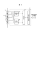
- FIG. 1 is a block diagram showing a configuration example of an electric vehicle system 1 according to the first embodiment.
- the electric system 1 in this embodiment includes a battery system 100, an inverter 400 connected to the battery system 100 via relays 300 and 310, and a motor 410 driven by the inverter 400.
- the vehicle control unit 200 determines the distribution of driving force, etc. based on information about the battery system 100 including the SOC, information from the inverter 400 and motor 410, information about the engine (not shown), and the like.
- the battery system 100 includes an assembled battery 110, a single cell management section 120, a current detection section 130, a voltage detection section 140 that detects the total voltage of the assembled battery 110, an assembled battery control section 150, and a storage section 180.
- the assembled battery 110 has a plurality of single cells 111.
- the single battery 111 is also referred to as a cell.
- the cell management unit 120 monitors the state of the cell 111.
- Current detection unit 130 detects the current flowing through battery system 100.
- the assembled battery control unit 150 controls the assembled battery 110.
- the storage unit 180 stores information regarding the battery characteristics of the assembled battery 110, the single battery 111, and the single battery group 112.
- the assembled battery control unit 150 stores the battery voltage and temperature of the single battery 111, the current value flowing through the battery, the total voltage value of the assembled battery 110, the diagnosis result of whether the single battery 111 is overcharged or overdischarged, and the single battery management unit. An abnormality signal, etc. that is output when a communication error occurs in 120 or the like is input.
- the battery voltage and temperature of the single battery 111 are output from the single battery management unit 120.
- the current value flowing through the battery is output from the current detection section 130.
- the total voltage value of the assembled battery 110 is output from the voltage detection section 140.
- the diagnosis result as to whether the unit cell 111 is overcharged or overdischarged and an abnormality signal that is output when a communication error occurs in the unit battery management unit 120 are output from the unit battery management unit 120.
- the battery pack control unit 150 detects the state of the battery pack 110 based on the input information. Further, the results of the processing performed by the assembled battery control section 150 are transmitted to the single cell management section 120 and the vehicle control section 200.
- the assembled battery 110 is configured by electrically connecting in series a plurality of single cells 111 that are capable of storing and releasing electrical energy (charging and discharging DC power).
- One cell 111 has an output voltage of 3.0 to 4.2V (average output voltage: 3.6V). It is assumed that the OCV (Open Circuit Voltage) and the SOC (State of Charge) of the cell 111 have a correlation shown in FIG. 4 . However, the voltage specification is not limited to this, and other voltage specifications may be used.
- the single cells 111 constituting the assembled battery 110 are grouped into a predetermined number of units in order to manage and control the state of the single cells 111.
- the grouped unit cells 111 are electrically connected in series to form a unit cell group 112.
- the predetermined number of units may be divided into equal categories such as 1, 4, 6, etc., or may be divided into multiple categories such as a combination of 4 and 6. There is also.
- the unit cell management unit 120 monitors the state of the unit cells 111 that constitute the assembled battery 110.
- the cell management section 120 is composed of a plurality of cell control sections 121, and one cell control section 121 is assigned to the cell group 112 grouped as described above.
- the unit cell control unit 121 operates by receiving power from the assigned unit battery group 112 and monitors the battery voltage and temperature of the unit cells 111 constituting the unit battery group 112.
- cell control units 121a and 121b are provided corresponding to cell groups 112a and 112b.
- the unit cell group 112 has a configuration in which four unit cells 111 are electrically connected in series, and furthermore, four unit batteries 111 are connected in series.
- the configuration is such that one single cell control unit 121 monitors, the present invention is not limited to this.
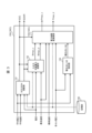
- FIG. 2 is a block diagram showing an example of the configuration of the unit cell control section 121 in the first embodiment.
- the cell control section 121 includes a voltage detection circuit 122, a control circuit 123, a signal input/output circuit 124, and a temperature detection section 125.
- the voltage detection circuit 122 measures the voltage between the terminals of each cell 111.
- the temperature detection unit 125 measures the temperature of the cell group 112.
- the control circuit 123 transmits each measurement result received from the voltage detection circuit 122 and the temperature detection section 125 to the assembled battery control section 150 via the signal input/output circuit 124.
- the circuit configuration for equalizing variations in voltage and SOC between the cells 111 that occur due to self-discharge, variation in current consumption, etc. is omitted as it is well known.
- the temperature detection unit 125 has a function of measuring the temperature of the cell group 112.
- the temperature detection unit 125 measures one temperature of the unit cell group 112 as a whole, and treats the measured temperature as a representative temperature value of the unit cells 111 constituting the unit cell group 112.
- the temperature measured by the temperature detection unit 125 is used in various calculations for detecting the state of the single cell 111, the single cell group 112, or the assembled battery 110.
- FIG. 2 shows an example in which one temperature detection section 125 is provided in the single cell control section 121.
- the temperature detection section 125 is simply shown.
- a temperature sensor is installed on the object to be measured, and the temperature sensor outputs temperature information as a voltage.
- the measurement result voltage output from the temperature sensor is transmitted to the signal input/output circuit 124 via the control circuit 123.
- the signal input/output circuit 124 outputs the measurement results to the outside of the cell control section 121.
- a function for realizing this series of processing is implemented in the cell control unit 121 as the temperature detection unit 125. Temperature information (voltage) can also be measured using the voltage detection circuit 122.
- the assembled battery control section 150 and the single cell management section 120 transmit and receive signals using the signal communication section 160 via an insulating element 170 such as a photocoupler.
- the reason why the insulating element 170 is provided is that the assembled battery control section 150 and the single cell management section 120 have different operating power sources. That is, the single battery management section 120 operates by receiving power from the assembled battery 110, whereas the assembled battery control section 150 uses a battery for an in-vehicle auxiliary device (for example, a 12V battery) as a power source.
- the insulating element 170 may be mounted on a circuit board that constitutes the unit cell management section 120 or may be mounted on a circuit board that constitutes the assembled battery control section 150. Note that depending on the system configuration, the insulating element 170 may be omitted.
- the cell control sections 121a and 121b are connected in series in descending order of the potential of the cell groups 112a and 112b that they monitor, respectively.
- the signal output by the assembled battery control section 150 is input to the single cell control section 121a by the signal communication section 160 via the insulating element 170.
- the output of the cell control section 121a and the input of the cell control section 121b are connected by the signal communication section 160, and signals are transmitted.
- the output of the cell control section 121b is input to the assembled battery control section 150 by the signal communication section 160 via the insulation element 170.
- This loop connection is also called a daisy chain connection, a daisy chain connection, or a daisy chain connection.
- the insulating element 170 is not interposed between the cell control section 121a and the cell control section 121b, but the insulating element 170 may be interposed therebetween.
- FIG. 3 is a block diagram showing a configuration example of the assembled battery control section 150 in the first embodiment.
- the assembled battery control section 150 includes a SOC/SOH calculation section 151, an input/output available power calculation section 152, a voltage variation detection section 153, and a power limit value calculation section 154.
- the SOC/SOH calculation unit 151 calculates the SOC and SOH by inputting the average voltage of the single cells 111 constituting the assembled battery 110, the current flowing through the assembled battery 110, and the average temperature of the single cells 111 detected by the temperature detection unit 125. Calculate and output.
- SOH deterioration rate
- SOHR State of Health based on Resistance
- SOHC State of Health based on Capacity
- the input/output possible power calculation unit 152 receives the SOC and SOHR calculated by the SOC/SOH calculation unit 151, the current of the assembled battery 110, and the lowest temperature in the battery system 100 as input, and calculates the maximum input/output power (input/output) of the battery.
- the output possible power (input possible power Wmax_c, output possible power Wmax_d)) is calculated and output.
- the voltage variation detection unit 153 receives the voltage and average voltage of each cell 111 as input, and calculates voltage variation information of each cell, for example, the difference between the highest cell voltage and the average voltage, and the difference between the lowest cell voltage and the average voltage. , and output voltage variations based on these.
- the power limit value calculation unit 154 calculates the input available power Wmax_c and output available power Wmax_d output by the input/output available power calculation unit 152, the SOC output by the SOC/SOH calculation unit 151, the minimum temperature and maximum temperature of each cell, and the The power limit value (input available power Pmax_c, output available power Pmax_d) is output by inputting the voltage and voltage variation output by the voltage variation detection unit 153.
- the storage unit 180 stores information such as internal resistance characteristics, capacity at full charge, polarization resistance characteristics, deterioration characteristics, individual difference information, and correspondence between SOC and OCV of the assembled battery 110, the single cells 111, and the single cell group 112. Store. Note that in this embodiment, the storage unit 180 is installed outside the assembled battery control unit 150 or the single cell management unit 120, but the assembled battery control unit 150 or the single battery management unit 120 may include the storage unit. It can also be a configuration.
- FIG. 4 is a diagram showing a configuration example of the SOC table 181 showing the relationship between SOC and OCV.
- the SOC table 181 is a data table that describes the correspondence between the OCV and SOC of the cell 111 for each temperature.
- FIG. 4 shows the correspondence between OCV and SOC at a certain temperature, and the correspondence between OCV and SOC at other temperatures is omitted.
- the numerical values shown in FIG. 4 are an example, and illustrate that the smaller the SOC, the smaller the OCV of the battery.
- the storage unit 180 also stores a data table that describes the correspondence between various battery characteristic information such as internal resistance characteristics and polarization resistance characteristics and various parameters such as SOC and temperature.
- the correspondence between SOC and OCV is shown in the SOC table 181, but the correspondence is not limited to a data table, and the correspondence may be represented by a mathematical formula or the like.
- the input/output available power calculating unit 152 calculates the maximum input/outputable current of the battery (input/output current (Input available current Imax_c, Output available current Imax_d)) is calculated and multiplied by the respective battery voltages when the input available current is energized, thereby outputting the available input power Wmax_c and the available output power Wmax_d.
- FIG. 5 is a diagram illustrating an example of an equivalent circuit model modeling the voltage behavior of the unit cell 111.
- the equivalent circuit in FIG. 5 has a configuration in which an electromotive force component indicating the OCV of the cell 111, a time-independent DC resistance component Ro, and a parallel circuit of a time-dependent polarization resistance component Rp and a capacitance C are connected in series. It has become.
- the parameters (OCV, Ro, Rp, C) of the equivalent circuit shown in FIG. 5 are extracted from test results using actual batteries. In this embodiment, these parameters are extracted for a new battery. Then, the DC resistance component Ro_new, which is an internal resistance component that does not depend on time when new, the polarization resistance component Rp_new, which is a time-dependent internal resistance component, and the polarization time constant ⁇ (the product of Rp and C) are determined by the SOC. Alternatively, it may be stored in the storage unit 180 as a map corresponding to the temperature.
- the SOH estimated by the SOC/SOH calculation unit 151 is reflected on the DC resistance component Ro_new stored in the storage unit 180, so that the DC resistance component Ro is calculated. .
- the SOH estimated by the SOC/SOH calculation unit 151 is reflected on the polarization resistance component Rp_new stored in the storage unit 180, so that the polarization resistance component Rp is Calculated.
- the voltage change Vp due to the polarization resistance component Rp is calculated as shown in equation (3) using the polarization resistance component Rp and the polarization time constant ⁇ , with the charging/discharging time being ts.
- the voltage change V due to the polarization resistance component Rp is obtained as a weighted average of the voltage (I ⁇ Rp) and the voltage Vp_z of the capacitor C.
- equation (4) is calculated. Then, as shown in equation (5), the available input current Imax_c and the available output current Imax_d are calculated.
- tcont is the number of continuous energization seconds (sec)
- Ilimit is the upper limit current value determined by taking into account the resistance of the relays, fuses, etc. that are the constituent members of the battery system 100.
- Vmax and Vmin indicate the upper limit voltage and lower limit voltage, respectively.
- the input/output available power calculation unit 152 uses the input available current Imax_c and the output available current Imax_d as input, and calculates the maximum input power (input available power Wmax_c) and the maximum output power using equations (6) and (7). (Output possible power Wmax_d) is calculated.
- N in equations (6) and (7) indicates the number of cells configuring battery system 100.
- FIG. 6 is a diagram showing an example of SOC and voltage waveforms when there is a battery with reduced capacity among the multi-series batteries.
- FIG. 6 as shown on the left side of the figure, it is assumed that one cell #1 with degraded capacity exists in a multi-series battery in which a plurality of unit cells 111 are connected in series.
- the SOC waveform is shown in the middle part of FIG. 6, and the voltage waveform is shown in the lower part of FIG. 6, respectively.
- the SOC of cell #1 decreases below the average SOC of all cells that make up the multi-series battery, and the voltage of cell #1 also decreases below the average voltage. I can see that This is because not only the capacitance but also the internal resistance of cell #1 has increased as the cell #1 has deteriorated, and the voltage change when current is applied is large. Additionally, as shown in Figure 4, the smaller the SOC, the smaller the OCV of the battery. be.
- the index shown in equation (8) is employed as the battery voltage variation.
- the larger value among the values is output as the battery voltage variation.
- voltage variation is the absolute value of the difference between the average voltage of all cells that make up a multi-series battery and the highest cell voltage among all cells, or the absolute value of the difference between the average voltage and the lowest cell voltage among all cells. Any one of these may be used in a fixed manner.
- the power limit value calculation unit 154 calculates the inputtable power Wmax_c and the outputtable power Wmax_d output by the input/outputtable power calculation unit 152, the maximum temperature and minimum temperature of the single cells 111 constituting the battery system 100, and the respective single cells 111.
- the voltage, the voltage variation detected by the voltage variation detection unit 153, and the SOC are input.
- the power limit value calculation unit 154 multiplies the input possible power Wmax_c by the input limit coefficient kchg (kchg ⁇ 1) and multiplies the output possible power Wmax_d by the output limit coefficient kdis (kdis ⁇ 1) according to each input value. to limit the input/output power.
- the power limit value calculation unit 154 multiplies the input possible power Wmax_c by the input limit coefficient kchg (kchg ⁇ 1) and multiplies the output possible power Wmax_d by the output limit coefficient kdis (kdis ⁇ 1) according to each input value. to limit the input/output power.
- all the single cells 111 are controlled so as not to deviate from the usage range of the SOC.
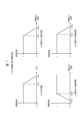
- FIG. 7 is a diagram for explaining an example of a method of calculating the input limit coefficient kchg in the power limit value calculation unit 154.
- FIG. 7 shows an example of an input restriction coefficient according to each input value for inputtable power Wmax_c during charging.
- the input restriction coefficient (first input restriction coefficient) according to the average SOC is shown. Set to 0 for Th12 or higher.
- FIG. 7(b) shows an input restriction coefficient (second input restriction coefficient) according to the highest cell voltage among the cells of the multi-series battery. It is lowered from 1 at , and set to 0 when it is equal to or higher than the threshold Th22.
- FIG. 7(c) shows an input limiting coefficient (third input limiting coefficient) according to the lowest cell temperature among the cells of the multi-series battery, and the input limiting coefficient is 0 when the lowest cell temperature is below the threshold Th31, and 0 when the lowest cell temperature is below the threshold Th31.
- the value is increased from 0, and is set to 1 when the value is equal to or higher than the threshold value Th32.
- FIG. 7(d) shows an input restriction coefficient (fourth input restriction coefficient) according to the highest cell temperature among the cells of the multi-series battery. It is decreased from 1 at , and set to 0 when it is equal to or higher than the threshold Th42.
- the power limit value calculation unit 154 calculates all input limit coefficients corresponding to each input value shown in FIGS. 7(a) to 7(d), and selects the minimum value of all input limit coefficients as the final input. Let the restriction coefficient be kchg. The power limit value calculation unit 154 multiplies the input possible power Wmax_c by the input restriction coefficient kchg to calculate the final input possible power Pmax_c, as shown in Equation (9), and outputs the result.
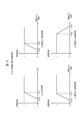
- FIG. 8 is a diagram for explaining an example of a method of calculating the output limit coefficient kdis in the power limit value calculation unit 154.
- FIG. 8 shows an example of an output limiting coefficient according to each input value for outputtable power Wmax_d during discharging.
- FIG. 8(a) shows the output limiting coefficient (first output limiting coefficient) according to the average SOC. Set to 0 when Th52 or less.
- FIG. 8(b) shows the output limiting coefficient (second output limiting coefficient) according to the lowest cell voltage among the cells of the multi-series battery. The value is decreased from 1 at , and becomes 0 when the value is equal to or less than the threshold Th62.
- (c) shows the output limiting coefficient (third output limiting coefficient) according to the lowest cell temperature among the cells of the multi-series battery. It is lowered from 1 at Th71, and becomes 0 at less than the threshold Th72.
- FIG. 8(d) shows the output limiting coefficient (fourth output limiting coefficient) according to the highest cell temperature among the cells of the multi-series battery.
- the output limiting coefficient is 0 when the highest cell temperature is equal to or higher than the threshold Th81, The value is increased from 0 and set to 1 when the value is less than or equal to the threshold Th82.
- the power limit value calculation unit 154 calculates all output limit coefficients according to each input value shown in FIGS. 8(a) to 8(d), and determines the minimum value of all output limit coefficients as the final output. Let the restriction coefficient be kdis. The power limit value calculation unit 154 calculates the final possible output power Pmax_d by multiplying the possible output power Wmax_d by the output restriction coefficient kdis, as shown in Equation (10), and outputs the result.
- FIG. 9 is a diagram for explaining the problem of power limit control based on average SOC.
- FIG. 9 shows that when there is a single cell 111 (cell #1) with a small capacity among the plurality of batteries constituting a multi-series battery, the average SOC of the multi-series battery as shown in the lower part of FIG.
- the waveforms of voltage (middle part of FIG. 9) and SOC (lower part of FIG. 9) when a current (upper part of FIG. 9) is input so as to fluctuate within the SOC usage range with an upper limit of 80% are shown.
- the voltage of cell #1 has a larger vertical fluctuation range than the average voltage of the multi-series battery. Therefore, it can be seen that the SOC of cell #1 deviates from the SOC usage range when the average SOC fluctuates within the SOC usage range of the lower limit of 30% and the upper limit of 80%.
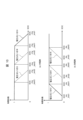
- FIG. 10 is a diagram for explaining an example of SOC restriction start timing according to voltage variations in the first embodiment.
- the horizontal axis shows the SOC
- the vertical axis shows the restriction coefficient.
- FIG. 10(a) shows the charging side, that is, the input restriction coefficient according to the SOC, and corresponds to FIG. 7(a).
- FIG. 10(b) shows the output limiting coefficient according to the discharge side, that is, the SOC, and corresponds to FIG. 8(a).
- the limit start point (the point where the limit coefficient starts to decrease) and the limit end point (the point where the limit coefficient decreases to 0) generally change. It is shifted to the left side of the diagram, that is, in the direction where the SOC becomes lower. This means that during charging, the start of the restriction according to the SOC is brought forward as the voltage variation among the cells in the multi-series battery becomes larger.
- the input restriction coefficient (first input restriction coefficient) according to the SOC is decreased from 1 when the SOC is SOC_chg_start1 or less, from 1 when the SOC_chg_start1 is SOC_chg_start1, and is set to 0 when the SOC is equal to or higher than SOC_chg_end1.
- the input restriction coefficient according to the SOC is decreased from 1 when the SOC is SOC_chg_start2 or less, from 1 when the SOC_chg_start2 is SOC_chg_start2, and is set to 0 when the SOC is SOC_chg_end2 or more.
- the input limiting coefficient according to the SOC is decreased from 1 when the SOC is SOC_chg_start3 or less, from 1 when the SOC_chg_start3 is SOC_chg_start3, and is set to 0 when the SOC is equal to or higher than SOC_chg_end3.
- the limit start point (the point where the limit coefficient starts to decrease) and the limit end point (the point where the limit coefficient decreases to 1) It is shifted to the right side of the figure, that is, in the direction where the SOC becomes higher. This means that during discharging, as the voltage variation of the cells of the multi-series battery increases, the start of restriction according to the SOC is accelerated.
- the output limiting coefficient (first output limiting coefficient) according to the SOC is decreased from 1 when the SOC is SOC_dis_start1 or higher, from 1 when SOC_dis_start1 is lower, and is set to 0 when the SOC is lower than SOC_dis_end1.
- the output limiting coefficient according to the SOC is decreased from 1 when the SOC is SOC_dis_start2 or more, from 1 when the SOC_dis_start2 is SOC_dis_start2, and is set to 0 when the SOC is below SOC_dis_end2.
- the output limiting coefficient according to the SOC is decreased from 1 when the SOC is SOC_dis_start3 or more, from 1 when the SOC_dis_start3 is SOC_dis_start3, and set to 0 when the SOC is equal to or less than SOC_dis_end3.
- Allowable input power Wmax_c and allowable output power Wmax_d can be controlled so as not to deviate from the range.
- FIG. 11 shows the limit start points (SOC_chg_start, SOC_dis_start) and limit end points (SOC_chg_end, SOC_dis_end) according to voltage variations on the charging side (FIG. 11(a)) and the discharging side (FIG. 11(b)), respectively. This is what is shown.
- the horizontal axis represents voltage variation and the vertical axis represents SOC.
- the power limit value calculation unit 154 refers to the SOC limit map corresponding to the voltage variation detected by the voltage variation detection unit 153, and determines input limit conditions (SOC_chg_start, SOC_chg_end) and output limit conditions (SOC_dis_start, SOC_dis_end) according to the SOC. is acquired and used to calculate the input/output restriction coefficient according to the SOC.
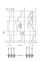
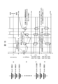
- FIG. 12 is a diagram showing examples of waveforms of power, voltage, SOC, input/output limiting coefficient, and input/output limiting conditions before applying the first embodiment.
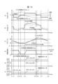
- FIG. 13 is a diagram illustrating an example of waveforms of power, voltage, SOC, input/output limiting coefficient, and input/output limiting condition after applying the first embodiment.
- FIGS. 12 and 13 show a certain case for a multi-series battery including a battery (cell #1) whose capacity has become smaller due to deterioration compared to other batteries among the plurality of batteries constituting the multi-series battery. It shows the time-series changes in each value when a load pattern is input.
- the values whose time-series changes are shown in FIGS. 12 and 13 are battery power, voltage, SOC, input limiting coefficient kchg, output limiting coefficient kdis, input limiting conditions (SOC_chg_start and SOC_chg_end), and output limiting conditions (SOC_dis_start and SOC_dis_end).
- a certain load pattern means that after inputting discharge power to the multi-series batteries for a predetermined time from time t11 to t13, there is a rest period from time t13 to t14, and then at time t14.
- the pattern is such that charging power is input to the multi-series batteries for a predetermined period of time from t16 to t16.
- the power waveform input to the multi-series battery is limited to be within the range of inputtable power Pmax_c and outputtable power Pmax_d.
- the average SOC is able to limit the output power without falling below the lower limit of 30%, but the SOC of cell #1 is smaller than the other cells due to its smaller capacity. It can be seen that the SOC changes significantly and is discharged below the lower limit of 30%.
- the input restriction coefficient kchg is determined based on the input restriction conditions (SOC_chg_start and SOC_chg_end), and the output restriction coefficient kdis is determined based on the output restriction conditions (SOC_dis_start and SOC_dis_end).
- the limiting coefficient is set to be smaller than "1" at an earlier timing than before the application of this embodiment.
- Ru That is, during charging, the input limiting coefficient kchg is set to be smaller than "1" from the time of a lower average SOC, and during discharging, the output limiting coefficient kdis is set to be smaller than "1" from the time of a higher average SOC. is set to Correspondingly, the available input power Pmax_c and the available output power Pmax_d also decrease.
- the output limiting coefficient kd is calculated based on the average SOC is set to "1" at time t22 when the SOC is higher than the lower limit of 30%.
- the input limiting coefficient kchg calculated based on the average SOC is lowered from "1" at time t25 when the SOC is lower than the upper limit of 80% and set to "0" at time t16, thereby increasing the capacity.
- the allowable input power Pmax_c can be controlled so that the SOC of the small battery (cell #1) does not exceed the upper limit.
- the input restriction coefficient kchg and the output restriction coefficient kdis by the average SOC are determined according to the larger value of the absolute values of the differences between the average voltage and the highest and lowest voltages of each cell voltage.
- the possible input power Pmax_c and the possible output power Pmax_d can be calculated so that the SOC of the battery with the smallest capacity does not deviate from the SOC usage range, without calculating the SOC of the multi-series batteries for each cell. .
- the battery control device that controls the battery assembly in which a plurality of batteries are connected detects the voltage variations of the plurality of batteries, and calculates the voltage variation based on the charging rate (average SOC) and the voltage variation of the battery assembly.
- the power that can be input and output from the assembled battery is limited based on the limit coefficient. Therefore, the battery with the lowest capacity among multiple batteries is detected based on the voltage variation, and a limiting coefficient according to the average SOC, which defines different limit start points and limit end points according to the voltage variation, is set at light loads. Can calculate. Further, when charging and discharging the assembled battery, it is possible to control the battery having the smallest capacity in the assembled battery so that it does not deviate from the SOC usage range.
- the voltage variation is an index based on the difference between the average voltage and the highest voltage of a plurality of batteries, or the difference between the average voltage and the lowest voltage. Therefore, it can be estimated by simple calculation that among a plurality of batteries, there is a battery whose capacity decreases and internal resistance increases due to deterioration, and which deviates from the SOC usage range during charging and discharging.
- the input/output power limit coefficient is calculated based on the voltage variation and the average SOC, and the input/output possible power is limited by multiplying the input/output possible power by the limit coefficient, so light load calculation
- the input/output power can be limited by
- the limit coefficient of the inputtable power according to the average SOC is 1 when the average SOC is below the first threshold, and starts decreasing from 1 at the first threshold, and when the average SOC is higher than the third threshold. It becomes 0 at the second threshold value, and 0 at the second threshold value or more, and the first threshold value and the second threshold value are smaller values as the voltage variation becomes larger. Therefore, the larger the voltage dispersion, the earlier the limit can be implemented to reduce the inputtable power from a certain point as the average SOC increases, and further reduce it to zero after a certain point.
- the minimum value of the input restriction coefficient according to the average SOC, the input restriction coefficient according to the maximum voltage of the battery, the input restriction coefficient according to the minimum temperature, and the input restriction coefficient according to the maximum temperature Let be the final input restriction coefficient. Therefore, the power that can be input and output can be limited so as to maximize the safety of the battery in terms of the four indicators of average SOC, maximum voltage, minimum temperature, and maximum temperature.
- the limit coefficient of the outputtable power according to the average SOC is 1 when the average SOC is equal to or higher than the third threshold, starts decreasing from 1 at the third threshold, and decreases when the average SOC is smaller than the third threshold. It becomes 0 at the fourth threshold, 0 below the fourth threshold, and the third and fourth thresholds have larger values as the voltage variation increases. Therefore, the larger the voltage variation, the earlier the control can be implemented to reduce the outputtable power from a certain point as the average SOC decreases, and further reduce it to zero after a certain point.
- the minimum value of the output limiting coefficient according to the average SOC, the output limiting coefficient according to the minimum voltage of the battery, the output limiting coefficient according to the minimum temperature, and the output limiting coefficient according to the maximum temperature is set. Let be the final output limiting coefficient. Therefore, the outputtable power can be limited so as to maximize battery safety in terms of the four indicators: average SOC, maximum voltage, minimum temperature, and maximum temperature.
- Embodiment 2 of the present invention will be described based on FIGS. 14 to 16.
- Embodiment 1 among the deviations between the maximum value and the average voltage of each battery voltage constituting the multi-series battery, and the deviation between the minimum value and the average voltage of each battery voltage, the value with the larger absolute value is defined as the voltage variation.
- the limit coefficient for input/output power based on the average SOC was determined accordingly.
- conditions for detecting voltage variations are not defined.
- the present invention aims to detect variations in the SOC of each battery that constitutes a multi-series battery, and to prevent the SOC of each battery from deviating from the SOC usage range. For this reason, it is desirable to detect voltage variations under conditions suitable for detecting SOC variations and determine the limit coefficient of input/outputable power.
- the battery system 100 includes a battery pack control section 150B instead of the battery pack control section 150.
- the assembled battery control section 150B includes a voltage variation detection section 153B instead of the voltage variation detection section 153.
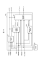
- FIG. 14 is a block diagram showing a configuration example of the assembled battery control section 150B in the second embodiment. Compared to the voltage variation detection unit 153 of the first embodiment, the voltage variation detection unit 153B has an additional input of the current value flowing through the assembled battery 110.
- the voltage variation detection unit 153B detects voltage variation on the condition that the current value added as an input is less than or equal to a predetermined value, and determines the input limiting coefficient kchg and the output limiting coefficient kdis.
- OCV all battery voltages
- FIG. 16 is a diagram showing an example of waveforms of current, voltage, SOC, and input/output restriction coefficient after applying the second embodiment. Similar to the explanatory diagram of the effect in Embodiment 1 (FIG. 13), the waveform is shown when a load pattern of repeated discharging and charging is input to a multi-series battery including one battery with a small capacity (cell #1). ing.
- the input limiting coefficient kchg and Determine the output limiting coefficient kd is.
- the allowable input power Pmax_c and the allowable output power Pmax_d are limited to be small.
- charging and discharging can be performed so that the SOCs of all batteries, including cell #1 with a small capacity, do not deviate from the SOC usage range.
- voltage variations and SOC variations can be evaluated more accurately by detecting voltage variations when the condition that the current value is equal to or less than a predetermined value is satisfied. Since the input/output restriction coefficient is determined according to the SOC based on accurate voltage variations, the possible input power Pmax_c and the possible output power Pmax_d can be adjusted so that the SOC of the battery with the smallest capacity does not deviate from the SOC usage range. Can be calculated accurately.
- Embodiment 3 of the present invention will be described based on FIGS. 17 and 18.
- the voltage variation which is the deviation between the maximum voltage and minimum voltage of a plurality of batteries constituting a multi-series battery, and the average voltage, is calculated when the condition that the current value flowing through the batteries is equal to or less than a predetermined value is satisfied. Detect in a limited manner. Then, based on the detected voltage variations, a limiting coefficient for the input/outputable power based on the average SOC is determined.
- FIG. 17 is a diagram for explaining problems in voltage variation detection.
- Figure 17(a) shows the current waveform input to the multi-series battery
- Figure 17(b) shows the voltage when the current in Figure 17(a) is input
- Figure 17(c) shows the current in Figure 17(a).
- the SOC waveforms when input are shown below.
- the power balance of charging and discharging will be ⁇ 0'' based on the state where the voltage and SOC of all the batteries are uniform at the time of starting discharge, and the SOC will be It will return to a uniform state again.
- the SOC of all batteries is uniform, the larger the change in SOC, the easier it is to identify batteries with smaller capacity, but in the range where the change in SOC is small, the SOC is uniform. It may be visible. Therefore, when detecting voltage variations, it may be falsely detected that no SOC variation has occurred, that is, no small capacity battery exists, and the input/output restriction conditions depending on the SOC may be relaxed.
- the above-mentioned false detection is prevented by continuing to maintain input/output restriction conditions according to the SOC determined by the largest voltage variation among the voltage variations detected after the battery started operating. Let's discuss an example.
- the battery system 100 has an assembled battery control section 150C instead of the assembled battery control section 150, and the assembled battery control section 150C performs power restriction instead of the power limit value calculation section 154. It has a value calculation section 154C (FIG. 3).
- the only difference is the processing content of power limit value calculation section 154C from power limit value calculation section 154, and the other configurations are the same.
- the power limit value calculation unit 154C determines the limit condition based on the average SOC according to the voltage variation based on FIGS. 10 and 11, if the voltage variation detected this time is a larger value than the voltage variation detected in the past, The voltage variation detected this time is used only in this case. If the voltage variation detected this time is smaller than the voltage variation detected in the past, the largest voltage variation among the voltage variations detected in the past is adopted. Voltage variations detected in the past are stored in a storage area such as the storage unit 180. As a result, voltage differences detected during charging and discharging under conditions that make it difficult to identify batteries with small capacity, as described above, are not used in voltage variation calculations, and this prevents the erroneous assumption that SOC variation has not occurred. Detection can be prevented.
- FIG. 18 is a diagram for explaining an example of a method for determining input/output limiting conditions according to voltage variations and SOC in the third embodiment.
- Figure 18(a) shows the current waveform input to the multi-series battery
- Figure 18(b) shows the voltage when the current is input
- Figure 18(c) shows the input limiting conditions according to the SOC when the current is input.
- FIG. 18(d) shows the output limiting conditions according to the SOC.
- the battery system 100 goes through discharging, resting, and discharging from before the start of discharging at time 0 when the voltage and SOC are uniform, then after a resting period, charging, A current for resting and charging is input.
- the method of detecting the voltage difference under the condition that the current value is less than or equal to a predetermined value in Embodiment 2 is applied, and the method of determining the input/output restriction conditions according to the SOC from the voltage variation immediately before the current is input after the pause is adopted.
- input/output limiting conditions are determined according to the SOC from voltage variations detected during the pause period immediately after the first discharge.
- the voltage variation increases compared to time 0. Therefore, the input limiting conditions (SOC_chg_start, SOC_chg_end) have smaller values as shown in FIG. 18(c), and the output limiting conditions (SOC_dis_start, SOC_dis_end) have larger values as shown in FIG. 18(d). Even after the second discharge, the SOC variations and voltage variations further expand, so the input/output restriction conditions according to the voltage variations become stricter conditions.
- the SOC variation and voltage variation decrease. If the voltage variation detected in the past is larger than the newly detected voltage variation, the newly detected voltage variation is not adopted, but the maximum voltage variation in the past is used, and the input is adjusted according to this voltage variation. Set output limit conditions.
- the present invention is not limited to the configuration of the above-described embodiment, but includes various modifications.
- the embodiments described above have been described in detail to explain the present invention in an easy-to-understand manner, and the present invention is not necessarily limited to having all the configurations described.
Landscapes
- Engineering & Computer Science (AREA)
- Power Engineering (AREA)
- Life Sciences & Earth Sciences (AREA)
- Sustainable Development (AREA)
- Sustainable Energy (AREA)
- Transportation (AREA)
- Mechanical Engineering (AREA)
- Chemical & Material Sciences (AREA)
- Manufacturing & Machinery (AREA)
- Chemical Kinetics & Catalysis (AREA)
- Electrochemistry (AREA)
- General Chemical & Material Sciences (AREA)
- Microelectronics & Electronic Packaging (AREA)
- Secondary Cells (AREA)
- Charge And Discharge Circuits For Batteries Or The Like (AREA)
- Electric Propulsion And Braking For Vehicles (AREA)
Abstract
Description
図1~図10に基づいて、本発明の実施形態1を説明する。
図1は、実施形態1における自動車の電動システム1の構成例を示すブロック図である。本実施形態における電動システム1は、電池システム100と、リレー300,310を介して電池システム100に接続されるインバータ400と、インバータ400によって駆動されるモータ410とを有する。車両制御部200は、SOCを始めとする電池システム100の情報や、インバータ400やモータ410からの情報、エンジン(不図示)の情報等をもとに駆動力の配分等を決定する。
図2は、実施形態1における単電池制御部121の構成例を示すブロック図である。単電池制御部121は、電圧検出回路122と、制御回路123と、信号入出力回路124と、温度検知部125とを有する。
図3は、実施形態1における組電池制御部150の構成例を示すブロック図である。本実施形態では、単電池111に関する診断結果や単電池管理部120に通信エラー等が発生した場合に出力される異常信号に基づく処理内容については、説明を省略する。組電池制御部150は、SOC/SOH演算部151と、入出力可能電力演算部152と、電圧ばらつき検知部153と、電力制限値演算部154とを有する。
図4は、SOCとOCVの関係を示すSOCテーブル181の構成例を示す図である。SOCテーブル181は、単電池111におけるOCVとSOCとの対応関係を温度毎に記述したデータテーブルである。図4は、ある温度におけるOCVとSOCとの対応関係を示し、他の温度におけるOCVとSOCとの対応関係は図示を省略している。図4に示す数値は一例であり、SOCが小さいほど電池のOCVも小さいことを例示する。




次に、図6を参照して、電圧ばらつき検知部153を説明する。図6は、多直列電池に容量低下の電池が存在する場合のSOCおよび電圧の波形の例を示す図である。図6では、図の左側に示すように、複数の単電池111を直列に接続した多直列電池内に、一つの容量劣化したセル#1が存在した場合を仮定している。この多直列電池に対して図6上段に示す電流を通電したときのSOCの波形を図6中段に、電圧の波形を図6下段にそれぞれ示している。

次に、図7~11を参照して、電力制限値演算部154を説明する。電力制限値演算部154は、入出力可能電力演算部152が出力する入力可能電力Wmax_cおよび出力可能電力Wmax_dと、電池システム100を構成する単電池111の最高温度および最低温度と、各単電池111の電圧と、電圧ばらつき検知部153が検知する電圧ばらつきと、SOCとを入力とする。そして、電力制限値演算部154は、各入力値に応じて、入力可能電力Wmax_cに入力制限係数kchg(kchg≦1)を乗じ、出力可能電力Wmax_dに出力制限係数kdis(kdis≦1)を乗じて、入出力可能電力を制限する。その結果、全ての単電池111がSOCの使用範囲を逸脱しないように制御される。


次に、本実施形態におけるSOCに応じた入出力制限係数の計算方法を図9~図11に基づき説明する。
本実施形態の効果を図12および図13をもとに説明する。図12は、実施形態1を適用前の電力、電圧、SOC、入出力制限係数、および入出力制限条件の波形の例を示す図である。図13は、実施形態1を適用後の電力、電圧、SOC、入出力制限係数、および入出力制限条件の波形の例を示す図である。

図14~図16に基づいて、本発明の実施形態2を説明する。
まず、図14を参照して、組電池制御部150Bについて説明する。図14は、実施形態2における組電池制御部150Bの構成例を示すブロック図である。電圧ばらつき検知部153Bは、実施形態1の電圧ばらつき検知部153と比較して、組電池110を流れる電流値が入力として追加されている。
図16を参照して本実施形態による効果を説明する。図16は、実施形態2を適用後の電流、電圧、SOC、および入出力制限係数の波形の例を示す図である。実施形態1における効果の説明図(図13)と同様に、容量の小さい電池(セル#1)を1つ含む多直列電池に対し、放電と充電を繰り返す負荷パターンを入力したときの波形を示している。
図17~図18に基づいて、本発明の実施形態3を説明する。
本実施形態によれば、検知した電圧ばらつきの時系列の中で最大の電圧ばらつきに応じて決定した入出力制限条件を維持し続ける。これにより、電圧ばらつきが存在するにもかかわらず存在しないとする誤検知を防止しつつ、容量の小さい電池をSOC使用範囲の逸脱なく充放電させることができる。
Claims (10)
- 複数の電池を接続した組電池を制御する電池制御装置であって、
前記複数の電池の電圧ばらつきを検知し、
前記組電池の充電率および前記電圧ばらつきに基づいて制限係数を演算し、
前記制限係数に基づいて前記組電池の入出力可能な最大電力である入出力可能電力を制限する
ことを特徴とする電池制御装置。 - 請求項1に記載の電池制御装置であって、
前記電圧ばらつきは、前記複数の電池の平均電圧と最高電圧との差分、または、前記平均電圧と前記複数の電池の最低電圧との差分である
ことを特徴とする電池制御装置。 - 請求項1または2に記載の電池制御装置であって、
前記充電率、前記組電池の劣化率と電流、および前記複数の電池の最低温度に基づいて前記入出力可能電力を演算する入出力可能電力演算部と、
前記複数の電池の平均電圧および各電圧に基づいて前記電圧ばらつきを検知する電圧ばらつき検知部と、
前記電圧ばらつきおよび前記充電率に基づいて前記制限係数を演算し、前記入出力可能電力に前記制限係数を乗算することで前記入出力可能電力を制限する電力制限値演算部と
を有することを特徴とする電池制御装置。 - 請求項3に記載の電池制御装置であって、
前記電力制限値演算部は、
前記制限係数として、前記充電率に応じて前記入出力可能電力のうちの入力可能電力を制限する第1入力制限係数を演算し、
前記第1入力制限係数は、前記充電率が、第1閾値以下で1であり、前記第1閾値で1から低下が開始して前記第1閾値より大の第2閾値で0になり、前記第2閾値以上で0であり、
前記第1閾値および前記第2閾値は、前記電圧ばらつきが大きいほど小さい値である
ことを特徴とする電池制御装置。 - 請求項4に記載の電池制御装置であって、
前記電力制限値演算部は、
さらに、前記複数の電池の最高電圧に応じて前記入力可能電力を制限する第2入力制限係数、前記複数の電池の最低温度に応じて前記入力可能電力を制限する第3入力制限係数、および前記複数の電池の最高温度に応じて前記入力可能電力を制限する第4入力制限係数を演算し、
前記第1入力制限係数乃至第4入力制限係数のうちの最小値を前記制限係数とする
ことを特徴とする電池制御装置。 - 請求項3~5の何れか1項に記載の電池制御装置であって、
前記電力制限値演算部は、
前記制限係数として、前記充電率に応じて前記入出力可能電力のうちの出力可能電力を制限する第1出力制限係数を演算し、
前記第1出力制限係数は、前記充電率が、第3閾値以上で1であり、前記第3閾値で1から低下が開始して前記第3閾値より小の第4閾値で0になり、前記第4閾値以下で0であり、
前記第3閾値および前記第4閾値は、前記電圧ばらつきが大きいほど大きい値である
ことを特徴とする電池制御装置。 - 請求項6に記載の電池制御装置であって、
前記電力制限値演算部は、
さらに、前記複数の電池の最低電圧に応じて前記出力可能電力を制限する第2出力制限係数、前記複数の電池の最低温度に応じて前記出力可能電力を制限する第3出力制限係数、および前記複数の電池の最高温度に応じて前記出力可能電力を制限する第4出力制限係数を演算し、
前記第1出力制限係数乃至第4出力制限係数のうちの最小値を前記制限係数とする
ことを特徴とする電池制御装置。 - 請求項1~7の何れか1項に記載の電池制御装置であって、
前記電圧ばらつきを、前記組電池の電流の絶対値が所定値以下ある場合に検知する
ことを特徴とする電池制御装置。 - 請求項1~8の何れか1項に電池制御装置であって、
前記複数の電池の電圧が均一のある時点以降に検知した前記電圧のばらつきの最大値に基づいて前記制限係数を演算する
ことを特徴とする電池制御装置。 - 前記組電池と、
請求項1~9の何れか1項記載の電池制御装置と
を有することを特徴とする電池システム。
Priority Applications (3)
| Application Number | Priority Date | Filing Date | Title |
|---|---|---|---|
| EP23784831.2A EP4507162A4 (en) | 2022-04-07 | 2023-04-24 | BATTERY CONTROL DEVICE AND BATTERY SYSTEM |
| US18/854,282 US20250233440A1 (en) | 2022-04-07 | 2023-04-24 | Battery control device and battery system |
| CN202380029010.5A CN118985077A (zh) | 2022-04-07 | 2023-04-24 | 电池控制装置及电池系统 |
Applications Claiming Priority (2)
| Application Number | Priority Date | Filing Date | Title |
|---|---|---|---|
| JP2022064167A JP7772643B2 (ja) | 2022-04-07 | 2022-04-07 | 電池制御装置および電池システム |
| JP2022-064167 | 2022-04-07 |
Publications (1)
| Publication Number | Publication Date |
|---|---|
| WO2023195548A1 true WO2023195548A1 (ja) | 2023-10-12 |
Family
ID=88243159
Family Applications (1)
| Application Number | Title | Priority Date | Filing Date |
|---|---|---|---|
| PCT/JP2023/016036 Ceased WO2023195548A1 (ja) | 2022-04-07 | 2023-04-24 | 電池制御装置および電池システム |
Country Status (5)
| Country | Link |
|---|---|
| US (1) | US20250233440A1 (ja) |
| EP (1) | EP4507162A4 (ja) |
| JP (1) | JP7772643B2 (ja) |
| CN (1) | CN118985077A (ja) |
| WO (1) | WO2023195548A1 (ja) |
Families Citing this family (1)
| Publication number | Priority date | Publication date | Assignee | Title |
|---|---|---|---|---|
| KR20240062488A (ko) * | 2022-11-01 | 2024-05-09 | 현대모비스 주식회사 | 배터리 관리 시스템 및 그 제어 방법 |
Citations (3)
| Publication number | Priority date | Publication date | Assignee | Title |
|---|---|---|---|---|
| JP3528428B2 (ja) | 1996-05-22 | 2004-05-17 | 日産自動車株式会社 | 電気自動車の電力制御装置 |
| JP2012110221A (ja) * | 2005-12-16 | 2012-06-07 | Hitachi Vehicle Energy Ltd | 蓄電池管理装置 |
| WO2012143996A1 (ja) * | 2011-04-18 | 2012-10-26 | 日立ビークルエナジー株式会社 | 蓄電装置 |
Family Cites Families (3)
| Publication number | Priority date | Publication date | Assignee | Title |
|---|---|---|---|---|
| JPH09203773A (ja) * | 1996-01-26 | 1997-08-05 | Nissan Motor Co Ltd | 組電池の残存容量計 |
| WO2010109956A1 (ja) * | 2009-03-27 | 2010-09-30 | 株式会社日立製作所 | 蓄電装置 |
| US20230170727A1 (en) | 2020-04-27 | 2023-06-01 | Nissan Motor Co., Ltd. | Output Control Method for Secondary Battery and Output Control System for Secondary Battery |
-
2022
- 2022-04-07 JP JP2022064167A patent/JP7772643B2/ja active Active
-
2023
- 2023-04-24 CN CN202380029010.5A patent/CN118985077A/zh active Pending
- 2023-04-24 EP EP23784831.2A patent/EP4507162A4/en active Pending
- 2023-04-24 WO PCT/JP2023/016036 patent/WO2023195548A1/ja not_active Ceased
- 2023-04-24 US US18/854,282 patent/US20250233440A1/en active Pending
Patent Citations (3)
| Publication number | Priority date | Publication date | Assignee | Title |
|---|---|---|---|---|
| JP3528428B2 (ja) | 1996-05-22 | 2004-05-17 | 日産自動車株式会社 | 電気自動車の電力制御装置 |
| JP2012110221A (ja) * | 2005-12-16 | 2012-06-07 | Hitachi Vehicle Energy Ltd | 蓄電池管理装置 |
| WO2012143996A1 (ja) * | 2011-04-18 | 2012-10-26 | 日立ビークルエナジー株式会社 | 蓄電装置 |
Non-Patent Citations (1)
| Title |
|---|
| See also references of EP4507162A4 |
Also Published As
| Publication number | Publication date |
|---|---|
| JP2023154671A (ja) | 2023-10-20 |
| CN118985077A (zh) | 2024-11-19 |
| EP4507162A1 (en) | 2025-02-12 |
| JP7772643B2 (ja) | 2025-11-18 |
| EP4507162A4 (en) | 2026-01-28 |
| US20250233440A1 (en) | 2025-07-17 |
Similar Documents
| Publication | Publication Date | Title |
|---|---|---|
| CN107533109B (zh) | 电池控制装置以及电动车辆系统 | |
| US9952288B2 (en) | Battery controller | |
| JP5819443B2 (ja) | 電池制御装置、電池システム | |
| EP3171187B1 (en) | Battery state detection device, secondary battery system, program product, and battery state detection method | |
| CN103608994B (zh) | 电池控制装置、电池系统 | |
| US9880224B2 (en) | Battery system monitoring device | |
| US20190288344A1 (en) | Battery Control Device | |
| EP3171186B1 (en) | Battery state detection device, secondary battery system, program product, and battery state detection method | |
| JP6101714B2 (ja) | 電池制御装置、電池システム | |
| EP3410558A1 (en) | Battery control device | |
| EP3260871B1 (en) | Battery system monitoring apparatus | |
| JP7605766B2 (ja) | 電池制御装置及び電池システム | |
| JP2023500449A (ja) | 急速充電方法 | |
| WO2014027389A1 (ja) | 電池制御装置、二次電池システム | |
| WO2010109956A1 (ja) | 蓄電装置 | |
| CN113016099B (zh) | 电池控制装置 | |
| JP7741971B2 (ja) | 電池制御装置及び電池制御方法 | |
| JP7772643B2 (ja) | 電池制御装置および電池システム | |
| EP4270590A1 (en) | Battery control device, and battery system | |
| EP4503259A1 (en) | Battery control device | |
| WO2023007872A1 (ja) | 電池制御方法 | |
| JP7103809B2 (ja) | 電池制御装置 | |
| KR20240154907A (ko) | 배터리 상태 추정 방법 및 그 방법을 제공하는 배터리 시스템 | |
| WO2026062787A1 (ja) | 電池制御システム | |
| CN122070229A (en) | Battery control system |
Legal Events
| Date | Code | Title | Description |
|---|---|---|---|
| 121 | Ep: the epo has been informed by wipo that ep was designated in this application |
Ref document number: 23784831 Country of ref document: EP Kind code of ref document: A1 |
|
| WWE | Wipo information: entry into national phase |
Ref document number: 202380029010.5 Country of ref document: CN |
|
| WWE | Wipo information: entry into national phase |
Ref document number: 18854282 Country of ref document: US |
|
| WWE | Wipo information: entry into national phase |
Ref document number: 2023784831 Country of ref document: EP |
|
| NENP | Non-entry into the national phase |
Ref country code: DE |
|
| ENP | Entry into the national phase |
Ref document number: 2023784831 Country of ref document: EP Effective date: 20241107 |
|
| WWP | Wipo information: published in national office |
Ref document number: 18854282 Country of ref document: US |