WO2023199587A1 - 空気調和システムの制御装置、空気調和システムの制御方法、プログラム、及び空気調和システム - Google Patents
空気調和システムの制御装置、空気調和システムの制御方法、プログラム、及び空気調和システム Download PDFInfo
- Publication number
- WO2023199587A1 WO2023199587A1 PCT/JP2023/004356 JP2023004356W WO2023199587A1 WO 2023199587 A1 WO2023199587 A1 WO 2023199587A1 JP 2023004356 W JP2023004356 W JP 2023004356W WO 2023199587 A1 WO2023199587 A1 WO 2023199587A1
- Authority
- WO
- WIPO (PCT)
- Prior art keywords
- heat exchanger
- indoor heat
- indoor
- ozone
- conditioning system
- Prior art date
- Legal status (The legal status is an assumption and is not a legal conclusion. Google has not performed a legal analysis and makes no representation as to the accuracy of the status listed.)
- Ceased
Links
Images



Classifications
-
- F—MECHANICAL ENGINEERING; LIGHTING; HEATING; WEAPONS; BLASTING
- F24—HEATING; RANGES; VENTILATING
- F24F—AIR-CONDITIONING; AIR-HUMIDIFICATION; VENTILATION; USE OF AIR CURRENTS FOR SCREENING
- F24F1/00—Room units for air-conditioning, e.g. separate or self-contained units or units receiving primary air from a central station
- F24F1/0007—Indoor units, e.g. fan coil units
- F24F1/0071—Indoor units, e.g. fan coil units with means for purifying supplied air
- F24F1/0076—Indoor units, e.g. fan coil units with means for purifying supplied air by electric means, e.g. ionisers or electrostatic separators
-
- F—MECHANICAL ENGINEERING; LIGHTING; HEATING; WEAPONS; BLASTING
- F24—HEATING; RANGES; VENTILATING
- F24F—AIR-CONDITIONING; AIR-HUMIDIFICATION; VENTILATION; USE OF AIR CURRENTS FOR SCREENING
- F24F1/00—Room units for air-conditioning, e.g. separate or self-contained units or units receiving primary air from a central station
- F24F1/02—Self-contained room units for air-conditioning, i.e. with all apparatus for treatment installed in a common casing
- F24F1/0328—Self-contained room units for air-conditioning, i.e. with all apparatus for treatment installed in a common casing with means for purifying supplied air
- F24F1/0353—Self-contained room units for air-conditioning, i.e. with all apparatus for treatment installed in a common casing with means for purifying supplied air by electric means, e.g. ionisers or electrostatic separators
-
- F—MECHANICAL ENGINEERING; LIGHTING; HEATING; WEAPONS; BLASTING
- F24—HEATING; RANGES; VENTILATING
- F24F—AIR-CONDITIONING; AIR-HUMIDIFICATION; VENTILATION; USE OF AIR CURRENTS FOR SCREENING
- F24F11/00—Control or safety arrangements
- F24F11/62—Control or safety arrangements characterised by the type of control or by internal processing, e.g. using fuzzy logic, adaptive control or estimation of values
- F24F11/63—Electronic processing
- F24F11/65—Electronic processing for selecting an operating mode
-
- F—MECHANICAL ENGINEERING; LIGHTING; HEATING; WEAPONS; BLASTING
- F24—HEATING; RANGES; VENTILATING
- F24F—AIR-CONDITIONING; AIR-HUMIDIFICATION; VENTILATION; USE OF AIR CURRENTS FOR SCREENING
- F24F11/00—Control or safety arrangements
- F24F11/70—Control systems characterised by their outputs; Constructional details thereof
- F24F11/72—Control systems characterised by their outputs; Constructional details thereof for controlling the supply of treated air, e.g. its pressure
- F24F11/79—Control systems characterised by their outputs; Constructional details thereof for controlling the supply of treated air, e.g. its pressure for controlling the direction of the supplied air
-
- F—MECHANICAL ENGINEERING; LIGHTING; HEATING; WEAPONS; BLASTING
- F24—HEATING; RANGES; VENTILATING
- F24F—AIR-CONDITIONING; AIR-HUMIDIFICATION; VENTILATION; USE OF AIR CURRENTS FOR SCREENING
- F24F8/00—Treatment, e.g. purification, of air supplied to human living or working spaces otherwise than by heating, cooling, humidifying or drying
- F24F8/20—Treatment, e.g. purification, of air supplied to human living or working spaces otherwise than by heating, cooling, humidifying or drying by sterilisation
- F24F8/24—Treatment, e.g. purification, of air supplied to human living or working spaces otherwise than by heating, cooling, humidifying or drying by sterilisation using sterilising media
- F24F8/26—Treatment, e.g. purification, of air supplied to human living or working spaces otherwise than by heating, cooling, humidifying or drying by sterilisation using sterilising media using ozone
-
- F—MECHANICAL ENGINEERING; LIGHTING; HEATING; WEAPONS; BLASTING
- F24—HEATING; RANGES; VENTILATING
- F24F—AIR-CONDITIONING; AIR-HUMIDIFICATION; VENTILATION; USE OF AIR CURRENTS FOR SCREENING
- F24F11/00—Control or safety arrangements
- F24F11/30—Control or safety arrangements for purposes related to the operation of the system, e.g. for safety or monitoring
- F24F11/48—Control or safety arrangements for purposes related to the operation of the system, e.g. for safety or monitoring prior to normal operation, e.g. pre-heating or pre-cooling
-
- F—MECHANICAL ENGINEERING; LIGHTING; HEATING; WEAPONS; BLASTING
- F24—HEATING; RANGES; VENTILATING
- F24F—AIR-CONDITIONING; AIR-HUMIDIFICATION; VENTILATION; USE OF AIR CURRENTS FOR SCREENING
- F24F2140/00—Control inputs relating to system states
- F24F2140/20—Heat-exchange fluid temperature
-
- F—MECHANICAL ENGINEERING; LIGHTING; HEATING; WEAPONS; BLASTING
- F24—HEATING; RANGES; VENTILATING
- F24F—AIR-CONDITIONING; AIR-HUMIDIFICATION; VENTILATION; USE OF AIR CURRENTS FOR SCREENING
- F24F2221/00—Details or features not otherwise provided for
- F24F2221/22—Cleaning ducts or apparatus
Definitions
- the present disclosure relates to an air conditioning system control device, an air conditioning system control method, a program, and an air conditioning system.
- Patent Document 1 discloses that after the cooling operation or dehumidification operation is completed, an ozone treatment operation is performed to supply ozone into the interior of the indoor unit, and after the ozone treatment operation is completed, a heating operation is performed to dry the internal surface of the indoor unit.
- a configuration is disclosed. In this configuration, the ozone treatment operation is performed in a state where the relative humidity inside the indoor unit is 70% or more.
- the present disclosure has been made to solve the above problems, and includes an air conditioning system control device, an air conditioning system control method, and an air conditioning system control method that can suppress the growth of mold while suppressing the influence on the indoor environment.
- the purpose is to provide programs, and air conditioning systems.
- a control device for an air conditioning system including an indoor unit equipped with an indoor heat exchanger and an ozone generator, an ozone irradiation control unit that irradiates the indoor heat exchanger with the ozone generated by the ozone, and an operation control unit that controls the operation mode of the indoor unit, and the ozone irradiation control unit irradiates the indoor heat exchanger with the ozone generated by
- the indoor heat exchanger is irradiated with ozone generated by a generator, the indoor unit is operated in a heating mode by the operation control unit, and the temperature of the indoor heat exchanger is equal to or higher than the internal temperature of the indoor unit, and By heating the indoor heat exchanger to maintain a temperature below .degree. C., the indoor heat exchanger, which has been moistened by irradiation with ozone, is dried.
- a method for controlling an air conditioning system is a method for controlling an air conditioning system including an indoor unit equipped with an indoor heat exchanger and an ozone generator, the method comprising: is applied to the indoor heat exchanger, the indoor unit is operated in a heating mode, and the temperature of the indoor heat exchanger is maintained at an internal temperature of the indoor unit or higher and below 45°C. By heating the room, the indoor heat exchanger, which is wet due to ozone irradiation, is dried.
- a program for an air conditioning system is configured to transmit ozone to a computer of a control device of an air conditioning system including an indoor unit equipped with an indoor heat exchanger and an ozone generator while the indoor heat exchanger is moist. irradiating the indoor heat exchanger, operating the indoor unit in a heating mode, and controlling the indoor heat exchanger so that the temperature of the indoor heat exchanger is maintained at an internal temperature of the indoor unit or higher and below 45°C. By heating, the indoor heat exchanger, which is wet due to ozone irradiation, is dried.
- An air conditioning system includes an indoor unit including an indoor heat exchanger and an ozone generator, and a control device that controls the operation of the indoor unit, and the control device controls the operation of the ozone generator.
- an ozone irradiation control unit that irradiates the indoor heat exchanger with generated ozone; and an operation control unit that controls an operation mode of the indoor unit, and the ozone generation control unit includes an ozone irradiation control unit that irradiates the indoor heat exchanger with generated ozone;
- the indoor heat exchanger is irradiated with ozone generated by a device, the indoor unit is operated in heating mode by the operation control unit, and the temperature of the indoor heat exchanger is equal to or higher than the internal temperature of the indoor unit, and is 45°C.
- air conditioning system control device air conditioning system control method, program, and air conditioning system of the present disclosure, it is possible to suppress the growth of mold while suppressing the influence on the indoor environment.
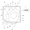
- FIG. 1 is a diagram showing a schematic configuration of an air conditioning system according to an embodiment of the present disclosure.
- FIG. 1 is a functional block diagram of a control device for an air conditioning system according to an embodiment of the present disclosure.
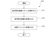
- 1 is a flowchart illustrating a procedure of a method for controlling an air conditioning system according to an embodiment of the present disclosure.
- FIG. 2 is a chart diagram showing operating modes, flaps, blower fans, and ozone generator states in the air conditioning system control method according to the embodiment of the present disclosure. It is a chart figure showing operation mode, a flap, a ventilation fan, and the state of an ozone generator in a control method of an air conditioning system concerning a modification of an embodiment of this indication.
- FIG. 1 is a diagram showing a hardware configuration of a control device for an air conditioning system according to an embodiment of the present disclosure.
- the air conditioning system 1 mainly includes an indoor unit 2, an outdoor unit (not shown), and a control device 4.
- the indoor unit 2 is installed indoors.
- the indoor unit 2 and the outdoor unit are connected by refrigerant piping (not shown).
- the indoor unit 2 takes in indoor air, adjusts the temperature and humidity, and then blows out the air indoors to condition the indoor air.
- the indoor unit 2 is fixed to the upper part of the indoor wall.
- the indoor unit 2 includes a housing 20 and a main body 21.
- the housing 20 accommodates a main body 21 therein.
- the housing 20 includes a back panel 20b, a front panel 20f, a top panel 20t, a bottom panel 20d, and a pair of side panels (not shown).
- the back panel 20b is fixed along an indoor wall surface.
- the back panel 20b side fixed to a wall surface will be described as the rear
- the front panel 20f side opposite to the back panel 20b will be described as the front.
- the front panel 20f covers the main body 21 from the front.
- the top panel 20t is provided at the top of the housing 20.
- the top panel 20t covers the main body 21 from above.
- a suction port (not shown) for sucking indoor air into the housing 20 is provided on the top panel 20t.
- the bottom panel 20d is provided at the bottom of the housing 20.
- the bottom panel 20d covers the main body 21 from below.
- An air outlet 20h is formed in the bottom panel 20d.
- the air outlet 20h is formed to vertically penetrate the bottom panel 20d.
- the air outlet 20h extends in the width direction of the housing 20 (the direction perpendicular to the plane of the paper in FIG. 1).
- the main body 21 includes an indoor heat exchanger 22, a blower fan 23, a flap 24, and an ozone generator 25.
- the indoor heat exchanger 22 is provided so as to surround the blower fan 23 from the outer circumferential side.
- the indoor heat exchanger 22 exchanges heat between the refrigerant supplied from an outdoor unit (not shown) and the atmosphere within the main body 21 .
- a drain pan (not shown) is provided below the indoor heat exchanger 22 to receive condensed water generated when the air inside the housing 20 is condensed (condensed) through heat exchange.
- the condensed water received by the drain pan is discharged outside through a drain pipe (not shown) connected to the drain pan.
- the blower fan 23 is rotationally driven by a motor (not shown) disposed within the housing 20 . Wind is generated within the housing 20 by the rotation of the blower fan 23. As the blower fan 23 rotates, air outside the housing 20 is sucked into the housing 20 through a suction port (not shown). A guide plate 26 is provided extending from the back side of the blower fan 23 to the air outlet 20h to guide the direction of air flow. The air sucked into the housing 20 is passed through the indoor heat exchanger 22, where it exchanges heat with the refrigerant. The air that has undergone heat exchange in the indoor heat exchanger 22 is guided along the guide plate 26 to the outlet 20h, and is blown into the room from the outlet 20h.
- the flap 24 is provided at the air outlet 20h.
- the flap 24 is provided so as to be rotatable around a rotation axis extending in the width direction of the housing 20 (a direction perpendicular to the paper surface of FIG. 1).
- the flap 24 opens and closes the air outlet 20h.
- the flap 24 is in an open state when the air conditioning system 1 is in operation.
- the flap 24 is in a closed state when the air conditioning system 1 is stopped, and covers the air outlet 20h.
- the ozone generator 25 is provided at a predetermined position within the housing 20.
- the ozone generator 25 generates ozone (O 3 ) and releases it into the housing 20.
- the ozone generator 25 is, for example, a discharge type ozone generator.
- the ozone generator 25 may be of a type other than a discharge type.
- the control device 4 controls the operation of the indoor unit 2. As shown in FIG. 2, the control device 4 includes a Central Processing Unit (hereinafter referred to as "CPU") 41 and a memory 42.
- CPU Central Processing Unit
- the CPU 41 functionally includes an operation control section 411, an ozone irradiation control section 412, and a flap control section 413. That is, the CPU 41 functions as an operation control section 411, an ozone irradiation control section 412, and a flap control section 413 by operating based on a predetermined program.
- the memory 42 stores various data acquired by the control device 4.
- the operation control unit 411 controls the operation mode of the indoor unit 2.
- the operation control unit 411 operates the indoor unit 2 in various preset operation modes such as cooling mode, dehumidification mode, heating mode, and ventilation mode.
- the operation control unit 411 operates the indoor unit 2 in a predetermined operation mode based on a user's operation input to a remote controller (not shown), setting input of a timer, etc.
- the operation control unit 411 causes the indoor unit 2 to perform an internal clean operation, which will be described in detail later, at the end of the operation in the cooling mode or the dehumidification mode.
- the ozone irradiation control section 412 controls the operation of the ozone generator 25.
- the ozone irradiation control unit 412 causes the ozone generator 25 to generate ozone.
- the ozone irradiation control unit 412 causes the indoor heat exchanger 22 to be irradiated with ozone generated by the ozone generator 25.
- Simply bringing ozone gas into contact with microorganisms (bacteria) such as mold in a dry state has little sterilizing effect. Therefore, the ozone irradiation control unit 412 causes the indoor heat exchanger 22 to be irradiated with ozone when the surface of the indoor heat exchanger 22 is in a wet state due to dew condensation water generated by heat exchange in the indoor heat exchanger 22.
- the ozone in the air within the housing 20 dissolves into water. This improves the sterilization effect. Note that the high affinity between water and microorganisms is also considered to be related to the improvement in the sterilization effect.
- the control method S10 of the air conditioning system 1 includes step S11 of irradiating the indoor heat exchanger with ozone, step S12 of drying the indoor heat exchanger, and step S12 of drying the indoor heat exchanger. and step S13 of blowing air.
- the control method S10 of the air conditioning system 1 is automatically executed when the operation of the indoor unit 2 in the cooling mode or dehumidification mode is stopped.
- the surface of the indoor heat exchanger 22 becomes moist (wet) with condensed water (condensed water).
- the surface of the indoor heat exchanger 22 is moistened by condensed water.
- Step S11 of irradiating the indoor heat exchanger with ozone is automatically started when a preset time (for example, several seconds) has elapsed after the indoor unit 2 stops operating in the cooling mode or dehumidification mode. be done.
- the ozone generator 25 is turned on as shown in FIG. 4 while the indoor heat exchanger 22 is wet, and the ozone generator 25 generates ozone.
- Ozone generated by the ozone generator 25 is irradiated onto the indoor heat exchanger 22.
- step S11 of irradiating the indoor heat exchanger with ozone the cooling mode operation is stopped and the blower fan 23 is turned off.
- step S11 of irradiating the indoor heat exchanger with ozone the flap 24 is opened.
- Step S11 of irradiating ozone to the indoor heat exchanger ozone is irradiated to the indoor heat exchanger 22 while the indoor heat exchanger 22 is moist, thereby removing bacteria such as mold attached to the indoor heat exchanger 22. reduced.
- step S12 of drying the indoor heat exchanger the indoor heat exchanger 22 which has been moistened by irradiation with ozone is dried.
- the operation control unit 411 causes the indoor unit 2 to operate in the heating mode and turns on the blower fan 23.
- the indoor heat exchanger 22, which has been moistened by the ozone irradiation is heated, and the indoor heat exchanger 22 is dried.
- step S12 of drying the indoor heat exchanger it is preferable to heat the indoor heat exchanger 22 so that the temperature of the indoor heat exchanger 22 is maintained at, for example, 30° C. or more and less than 45° C.
- step S12 of drying the indoor heat exchanger it is particularly preferable to heat the indoor heat exchanger 22 so that the temperature of the indoor heat exchanger 22 is maintained at, for example, 35°C or higher and lower than 45°C.
- the flap 24 is controlled by the flap control unit 413 so that the blowing air W is directed toward the front of the indoor unit 2.
- the blown air W is guided by the flap 24 so as to flow from the air outlet 20h toward the front of the indoor unit 2.
- the temperature of the blowing air W is higher than room temperature. Therefore, a part of the blown air W rises indoors and flows along the front surface of the indoor unit 2. As a result, the temperature around the indoor unit 2 increases, and the temperature difference between the inside and outside of the indoor unit 2 is suppressed. Furthermore, the flap 24 prevents warm air flowing out from the indoor unit 2 from flowing downward. After a preset predetermined time has elapsed, step S12 of drying the indoor heat exchanger 22 is ended.
- step S13 of blowing air with the blowing fan the blowing fan 23 blows air onto the indoor heat exchanger 22 that has been dried in step S12 of drying the indoor heat exchanger 22. In this way, by blowing air with the blower fan 23 after drying the indoor heat exchanger 22, the moisture remaining on the surface of the indoor heat exchanger 22 is further reduced. After a preset predetermined time has elapsed, step S13 of blowing air with the blower fan ends.
- the control device 4 of the air conditioning system 1 irradiates the indoor heat exchanger 22 with ozone while the indoor heat exchanger 22 is moist. Thereby, bacteria such as mold adhering to the indoor heat exchanger 22 are reduced. Further, the control device 4 dries the indoor heat exchanger 22, which has been irradiated with ozone and remains wet. This reduces the amount of moisture remaining on the surface of the indoor heat exchanger 22. Therefore, the proliferation of bacteria such as mold is suppressed while the indoor unit 2 is stopped. When drying the indoor heat exchanger 22, the indoor unit 2 is operated in heating mode.
- the indoor heat exchanger 22 is heated so that the temperature of the indoor heat exchanger 22 is maintained at the internal temperature of the indoor unit 2 or higher and below 45°C. Therefore, the amount of warm air flowing into the room from the indoor heat exchanger 22 can be suppressed, and the rise in temperature in the room can be suppressed.
- the control device 4 suppresses the temperature of the indoor heat exchanger 22 to below 45°C. This suppresses dew condensation on the surface of the casing. In this way, it is possible to suppress the growth of mold while suppressing the influence on the indoor environment.
- the control device 4 adjusts the opening degree of the flap 24 so that the blowing air W is directed toward the front of the indoor unit 2.
- a part of the blown wind W directed toward the front of the indoor unit 2 is higher than the room temperature, so it rises indoors and flows along the front surface of the indoor unit 2.
- the temperature around the indoor unit 2 increases, and the temperature difference between the inside and outside of the indoor unit 2 is suppressed. Therefore, the occurrence of dew condensation on the surface of the housing 20 can be suppressed.
- the opening degree of the flap 24 so that the blown air W is directed toward the front of the indoor unit 2 warm air flowing out from the indoor unit 2 is prevented from going downward. A user often exists in a space below the indoor unit 2 indoors. Therefore, warm air generated to dry the indoor heat exchanger 22 is prevented from reaching the user.
- the control device 4 when irradiating ozone, operates the indoor unit 2 in the cooling mode or dehumidification mode. As a result, moisture in the air condenses around the indoor heat exchanger 22, and dew condensation water is generated. Bacteria such as mold that has been sterilized by ozone irradiation is discharged from the indoor heat exchanger 22 along with this dew condensation water. Therefore, it becomes possible to suppress the growth of mold more effectively.
- the control device blows air with the blower fan 23. Thereby, the moisture remaining on the surface of the indoor heat exchanger 22 can be further reduced.
- the control method S10 of the air conditioning system 1 after irradiating the indoor heat exchanger 22 with ozone while the indoor heat exchanger 22 is wet, when drying the indoor heat exchanger 22, causes the indoor unit 2 to operate in heating mode. At this time, the indoor heat exchanger 22 is heated so that the temperature of the indoor heat exchanger 22 is maintained at the internal temperature of the indoor unit 2 or higher and below 45°C. Therefore, occurrence of dew condensation on the surface of the housing 20 is suppressed. In this way, it is possible to suppress the growth of mold while suppressing the influence on the indoor environment.
- the air conditioning system 1 irradiates the indoor heat exchanger 22 with ozone while the indoor heat exchanger 22 is moist. Thereby, bacteria such as mold adhering to the indoor heat exchanger 22 are reduced. Furthermore, the air conditioning system 1 is irradiated with ozone and dries the indoor heat exchanger 22 which remains moist. This reduces the amount of moisture remaining on the surface of the indoor heat exchanger 22. Therefore, the proliferation of bacteria such as mold is suppressed while the indoor unit 2 is stopped. When drying the indoor heat exchanger 22, the indoor unit 2 is operated in heating mode. At this time, the indoor heat exchanger 22 is heated so that the temperature of the indoor heat exchanger 22 is maintained at the internal temperature of the indoor unit 2 or higher and below 45°C.
- the amount of warm air flowing into the room from the indoor heat exchanger 22 can be suppressed, and the rise in temperature in the room can be suppressed. Further, by suppressing the temperature of the indoor heat exchanger 22 to less than 45° C., the occurrence of dew condensation on the surface of the housing 20 can be suppressed. In this way, it is possible to suppress the growth of mold while suppressing the influence on the indoor environment.
- step S11 of irradiating the indoor heat exchanger with ozone the operation in the cooling mode is stopped and the blower fan 23 is turned off, but the present invention is not limited to this.
- the operation control unit 411 operates the indoor unit 2 in the cooling mode or dehumidification mode, and while the blower fan 23 is turned on, ozone is applied to the indoor heat exchanger 22.
- the indoor unit 2 is caused to perform the internal clean operation as described above at the end of the operation in the cooling mode or the dehumidification mode, but the invention is not limited to this.
- the operation control unit 411 may cause the indoor unit 2 to perform the internal clean operation as described above after completing the operation in the heating mode, the ventilation mode, or the like.
- the indoor heat exchanger 22 is not sufficiently moistened, the sterilization effect of ozone irradiation will be reduced.
- the operation control unit 411 when performing internal clean operation after completion of operation in heating operation mode, ventilation mode, etc., the operation control unit 411 performs operation in cooling mode or dehumidification mode for a certain period of time prior to ozone irradiation. Good too.
- the surface of the indoor heat exchanger 22 is moistened by the condensed water, and the sterilization effect of ozone irradiation is enhanced.
- the humidity in the housing 20 of the indoor unit 2 is lower than a preset lower limit even after the operation in the heating operation mode, ventilation mode, etc. mode or dehumidification mode may be operated for a certain period of time.
- programs for realizing various functions of the control device 4 are recorded on a computer-readable recording medium, and the programs recorded on the recording medium are read into a computer system such as a microcomputer. , various processes are performed by executing.
- various processes of the CPU of the computer system are stored in a computer-readable recording medium in the form of a program, and the various processes described above are performed by reading and executing this program by the computer.
- the computer-readable recording medium refers to a magnetic disk, a magneto-optical disk, a CD-ROM, a DVD-ROM, a semiconductor memory, and the like.
- this computer program may be distributed to a computer via a communication line, and the computer receiving the distribution may execute the program.
- the computer included in the control device 4 includes a CPU 41, a memory 42, a storage/playback device 50, an input/output interface (hereinafter referred to as "IO I/F") 51, and a communication interface ( (hereinafter referred to as "communication I/F”) 52.
- IO I/F input/output interface
- communication I/F communication interface
- the memory 42 is a medium such as Random Access Memory (hereinafter referred to as "RAM") that temporarily stores data used in programs executed by the control device 4.
- the storage/playback device 50 is a device for storing data and the like in external media such as CD-ROM, DVD, and flash memory, and for playing back data and the like from the external media.
- the IO I/F 51 is an interface for inputting and outputting information between the control device 4 and other devices.
- the communication I/F 52 is an interface that communicates with other devices via a communication line such as the Internet or a dedicated communication line.
- control device 4 of the air conditioning system 1, the control method S10 of the air conditioning system 1, the program, and the air conditioning system 1 described in the embodiment are understood as follows, for example.
- the control device 4 of the air conditioning system 1 is the control device 4 of the air conditioning system 1 including the indoor unit 2 equipped with an indoor heat exchanger 22 and an ozone generator 25,
- the indoor heat exchanger includes an ozone irradiation control unit 412 that irradiates the indoor heat exchanger 22 with ozone generated by the ozone generator 25, and an operation control unit 411 that controls the operation mode of the indoor unit 2.
- the indoor heat exchanger 22 is irradiated with ozone generated by the ozone generator 25, and the operation control section 411 operates the indoor unit 2 in the heating mode to perform the indoor heat exchange.
- the indoor heat exchanger 22 is irradiated with ozone and becomes moist. Dry.
- the control device 4 of the air conditioning system 1 reduces bacteria such as mold attached to the indoor heat exchanger 22 by irradiating the indoor heat exchanger 22 with ozone while the indoor heat exchanger 22 is moist. Ru. Furthermore, the amount of moisture remaining on the surface of the indoor heat exchanger 22 is reduced by irradiating ozone and drying the indoor heat exchanger 22 which remains wet. This prevents bacteria such as mold from propagating while the indoor unit 2 is stopped. When drying the indoor heat exchanger 22, the indoor unit 2 is operated in heating mode. At this time, the indoor heat exchanger 22 is heated so that the temperature of the indoor heat exchanger 22 is maintained at the internal temperature of the indoor unit 2 or higher and below 45°C.
- the amount of warm air flowing into the room from the indoor heat exchanger 22 can be suppressed, and the rise in temperature in the room can be suppressed. Furthermore, if the temperature is set too high when drying the indoor heat exchanger 22, the temperature difference between the inside and outside of the casing 20 of the indoor unit 2 will increase, and dew condensation may occur on the surface of the casing 20. However, by suppressing the temperature of the indoor heat exchanger 22 to less than 45° C., the occurrence of dew condensation on the surface of the casing 20 can be suppressed. In this way, it is possible to suppress the growth of mold while suppressing the influence on the indoor environment.
- the control device 4 of the air conditioning system 1 is the control device 4 of the air conditioning system 1 of (1), and is a flap that adjusts the direction of the blowing wind W blown out from the indoor unit 2.
- the flap control unit 413 controls the flap 24 so that the blowing air W is directed toward the front of the indoor unit 2. control.
- the flap 24 directs the blown air W toward the front of the indoor unit 2.
- a part of the blown wind W directed toward the front of the indoor unit 2 is higher than the room temperature, so it flows along the front surface of the indoor unit 2 indoors.
- the temperature around the indoor unit 2 increases, the temperature difference between the inside and outside of the indoor unit 2 can be suppressed, and the occurrence of dew condensation can be suppressed.
- warm air flowing out from the indoor unit 2 is prevented from flowing downward to the indoor unit 2. Since users are often indoors in a space below the indoor unit 2, warm air generated to dry the indoor heat exchanger 22 is prevented from reaching the users.
- the control device 4 of the air conditioning system 1 is the control device 4 of the air conditioning system 1 of (1) or (2), and in the ozone irradiation, the operation control unit 411
- the indoor heat exchanger 22 is irradiated with the ozone while the indoor unit is operated in the cooling mode or dehumidification mode.
- the control device 4 of the air conditioning system 1 according to the fourth aspect is the control device 4 of the air conditioning system 1 according to any one of (1) to (3), and is the control device 4 of the air conditioning system 1 according to any one of (1) to (3).
- air is blown onto the dried indoor heat exchanger 22 by a blower fan 23.
- a control method S10 for an air conditioning system 1 is a control method S10 for an air conditioning system 1 including an indoor unit 2 equipped with an indoor heat exchanger 22 and an ozone generator 25, While the indoor heat exchanger 22 is moist, the indoor heat exchanger 22 is irradiated with ozone, the indoor unit 2 is operated in heating mode, and the temperature of the indoor heat exchanger 22 is adjusted to the temperature inside the indoor unit 2. By heating the indoor heat exchanger 22 to maintain the temperature at a temperature higher than 45° C., the indoor heat exchanger 22, which is wet due to ozone irradiation, is dried.
- the indoor unit 2 is operated in the heating mode.
- the indoor heat exchanger 22 is heated so that the temperature of the indoor heat exchanger 22 is maintained at the internal temperature of the indoor unit 2 or higher and below 45°C. Therefore, the amount of warm air flowing into the room from the indoor heat exchanger 22 can be suppressed, and the rise in temperature in the room can be suppressed. Furthermore, if the temperature is set too high when drying the indoor heat exchanger 22, the temperature difference between the inside and outside of the casing 20 of the indoor unit 2 will increase, and dew condensation may occur on the surface of the casing 20.
- the program according to the sixth aspect is configured such that the indoor heat exchanger 22 is installed in a computer of a control device 4 of an air conditioning system 1 including an indoor unit 2 equipped with an indoor heat exchanger 22 and an ozone generator 25.
- the indoor heat exchanger 22 is irradiated with ozone, the indoor unit 2 is operated in a heating mode, and the temperature of the indoor heat exchanger 22 is equal to or higher than the internal temperature of the indoor unit 2 and lower than 45°C.
- the indoor heat exchanger 22 which has been moistened by ozone irradiation, is dried.
- the indoor unit 2 is operated in the heating mode.
- the indoor heat exchanger 22 is heated so that the temperature of the indoor heat exchanger 22 is maintained at the internal temperature of the indoor unit 2 or higher and below 45°C. Therefore, the amount of warm air flowing into the room from the indoor heat exchanger 22 can be suppressed, and the rise in temperature in the room can be suppressed. Furthermore, if the temperature is set too high when drying the indoor heat exchanger 22, the temperature difference between the inside and outside of the casing 20 of the indoor unit 2 will increase, and dew condensation may occur on the surface of the casing 20.
- the air conditioning system 1 includes an indoor unit 2 including an indoor heat exchanger 22 and an ozone generator 25, and a control device 4 that controls the operation of the indoor unit 2.
- the control device 4 includes an ozone irradiation control unit 412 that irradiates the indoor heat exchanger 22 with ozone generated by the ozone generator 25, and an operation control unit 411 that controls the operation mode of the indoor unit 2.
- the indoor heat exchanger 22 is irradiated with ozone generated by the ozone generator 25 while the indoor heat exchanger 22 is moist, and the operation control section 411 sets the indoor unit 2 in a heating mode.
- the state is irradiated with ozone and becomes moist.
- the indoor heat exchanger 22 is dried.
- the indoor heat exchanger 22 is operated in heating mode. At this time, the indoor heat exchanger 22 is heated so that the temperature of the indoor heat exchanger 22 is maintained at the internal temperature of the indoor unit 2 or higher and below 45°C.
- the amount of warm air flowing into the room from the indoor heat exchanger 22 can be suppressed, and the rise in temperature in the room can be suppressed. Furthermore, if the temperature is set too high when drying the indoor heat exchanger 22, the temperature difference between the inside and outside of the casing 20 of the indoor unit 2 will increase, and dew condensation may occur on the surface of the casing 20. However, by suppressing the temperature of the indoor heat exchanger 22 to less than 45° C., the occurrence of dew condensation on the surface of the casing 20 can be suppressed. In this way, it is possible to suppress the growth of mold while suppressing the influence on the indoor environment.
- air conditioning system control device air conditioning system control method, program, and air conditioning system of the present disclosure, it is possible to suppress the growth of mold while suppressing the influence on the indoor environment.
Landscapes
- Engineering & Computer Science (AREA)
- Chemical & Material Sciences (AREA)
- Combustion & Propulsion (AREA)
- Mechanical Engineering (AREA)
- General Engineering & Computer Science (AREA)
- Signal Processing (AREA)
- Physics & Mathematics (AREA)
- Fuzzy Systems (AREA)
- Mathematical Physics (AREA)
- Air Conditioning Control Device (AREA)
- Devices For Blowing Cold Air, Devices For Blowing Warm Air, And Means For Preventing Water Condensation In Air Conditioning Units (AREA)
- Air Filters, Heat-Exchange Apparatuses, And Housings Of Air-Conditioning Units (AREA)
Abstract
Description
本願は、2022年4月15日に日本に出願された特願2022-067587号について優先権を主張し、その内容をここに援用する。
以下、本開示の実施形態に係る空気調和システムの制御装置、空気調和システムの制御方法、プログラム、及び空気調和システムについて、図1~図4を参照して説明する。
図1に示すように空気調和システム1は、室内機2と、室外機(図示せず)と、制御装置4と、を主に備える。
室内機2は、室内に設置される。
室内機2と室外機とは、冷媒配管(図示せず)によって接続されている。
室内機2は、室内の空気を吸い込んで温度や湿度の調整を行った後、空気を室内に吹き出すことで、室内の空気調和を行う。
室内機2は、室内の壁面の上部に固定される。
室内機2は、筐体20と、本体21と、を備える。
筐体20は、背面パネル20bと、前面パネル20fと、天面パネル20tと、底面パネル20dと、一対の側面パネル(図示せず)と、を備える。
本明細書において、壁面に固定される背面パネル20b側を後方、背面パネル20bとは反対側の前面パネル20f側を前方として説明を行う。
前面パネル20fは、本体21を前方から覆う。
天面パネル20tは、本体21を上方から覆う。
天面パネル20tには、筐体20内に室内の空気を吸い込む吸込口(図示せず)が設けられる。
底面パネル20dは、筐体20の底部に設けられる。
底面パネル20dは、本体21を下方から覆う。
底面パネル20dには、吹出口20hが形成される。
吹出口20hは、底面パネル20dを上下に貫通するように形成される。
吹出口20hは、筐体20の幅方向(図1において紙面に直交する方向)に延びている。
室内熱交換器22は、送風ファン23を外周側から囲むように設けられる。
室内熱交換器22は、室外機(図示せず)から送給される冷媒と、本体21内の雰囲気との熱交換を行う。
室内熱交換器22の下側には、熱交換によって筐体20内の空気が凝縮(結露)することによって生じた結露水を受けるドレンパン(図示せず)が設けられる。
ドレンパンで受けた結露水は、ドレンパンに接続された排水管(図示せず)を通して室外に排出される。
送風ファン23の回転により、筐体20内で風が発生される。
送風ファン23の回転により、筐体20の外部の空気が、吸込口(図示せず)から筐体20内に吸い込まれる。
送風ファン23の背面側から吹出口20hにわたって、空気の流れ方向を案内する案内板26が設けられている。
筐体20内に吸い込まれた空気は、室内熱交換器22に流通され、冷媒との熱交換がなされる。
室内熱交換器22で熱交換がなされた空気は、案内板26に沿って吹出口20hへと案内され、吹出口20hから室内に吹き出される。
フラップ24は、筐体20の幅方向(図1の紙面に直交する方向)に延びる回転軸周りに回動可能に設けられる。
フラップ24は、吹出口20hを開閉する。
フラップ24は、空気調和システム1の運転時に開状態となる。
フラップ24は、空気調和システム1の停止時には閉状態となり、吹出口20hを覆う。
フラップ24は、その開度を調整することで、吹出口20hから吹き出す吹出風の風向を調整可能である。
オゾン発生器25は、オゾン(O3)を発生し、筐体20内に放出する。
オゾン発生器25は、例えば、放電式のオゾン発生器である。
オゾン発生器25は、放電式以外のものであってもよい。
制御装置4は、室内機2の動作を制御する。
図2に示すように、制御装置4は、Central Processing Unit(以下、「CPU」という。)41と、メモリ42と、を備える。
すなわち、CPU41は、所定のプログラムに基づいて動作することで、運転制御部411、オゾン照射制御部412、及びフラップ制御部413としての機能を発揮する。
メモリ42は、制御装置4が取得する各種データを格納する。
運転制御部411は、冷房モード、除湿モード、暖房モード、送風モードなど、予め設定された各種運転モードで室内機2を運転する。
運転制御部411は、リモートコントローラ(図示せず)に対するユーザの操作入力、タイマー等の設定入力等により、所定の運転モードで室内機2を運転する。
運転制御部411は、冷房モード、又は除湿モードによる運転の終了時に、後に詳述するような内部クリーン運転を、室内機2に実施させる。
オゾン照射制御部412は、オゾン発生器25によりオゾンを発生させる。
オゾン照射制御部412は、オゾン発生器25により発生したオゾンを、室内熱交換器22に照射させる。
乾燥状態でカビ等の微生物(菌)にオゾンガスを接触させるだけでは、除菌効果が小さい。そこで、オゾン照射制御部412は、室内熱交換器22の表面が、室内熱交換器22における熱交換によって生じる結露水によって湿潤状態にあるときに、オゾンを室内熱交換器22に照射させる。
湿潤状態にある室内熱交換器22に、オゾンを照射させると、筐体20内の空気中のオゾンが水に溶け込む。これにより、除菌効果が向上する。なお、水と微生物の親和性が高いことも、除菌効果の向上に関係すると考えられる。
図3に示すように、本開示の実施形態に係る空気調和システム1の制御方法S10は、室内熱交換器にオゾンを照射するステップS11と、室内熱交換器を乾燥させるステップS12と、送風ファンにより送風させるステップS13と、を含む。
本実施形態において、空気調和システム1の制御方法S10は、室内機2の冷房モード、又は除湿モードによる運転を停止した場合、自動的に実行される。
室内機2が冷房モード、又は除湿モードによる運転を行っている場合、室内熱交換器22の表面は、結露した水(結露水)によって湿潤する(濡れる)。
室内機2が冷房モード、又は除湿モードによる運転を停止した直後において、室内熱交換器22の表面は、結露水によって湿潤している。
室内熱交換器にオゾンを照射するステップS11では、室内熱交換器22が湿潤した状態で、図4に示すように、オゾン発生器25をONに切り換え、オゾン発生器25でオゾンを発生させる。
オゾン発生器25で発生されたオゾンは、室内熱交換器22に照射される。
室内熱交換器にオゾンを照射するステップS11では、冷房モードによる運転を停止し、送風ファン23をOFFとする。
室内熱交換器にオゾンを照射するステップS11では、フラップ24を開く。
室内熱交換器にオゾンを照射するステップS11では、室内熱交換器22が湿潤した状態で、オゾンを室内熱交換器22に照射することで、室内熱交換器22に付着したカビ等の菌が低減される。
室内熱交換器を乾燥させるステップS12では、図4に示すように、運転制御部411により室内機2を暖房モードで運転させ、送風ファン23をONに切り換える。これにより、オゾンが照射されて湿潤した状態の室内熱交換器22が加熱され、室内熱交換器22が乾燥される。
室内熱交換器を乾燥させるステップS12では、室内熱交換器22の温度が室内機2の内部温度以上、かつ45℃未満を維持するように、室内熱交換器22を加熱するのが好ましい。
室内熱交換器を乾燥させるステップS12では、室内熱交換器22の温度が、例えば、30℃以上、かつ45℃未満を維持するように、室内熱交換器22を加熱するのが好ましい。
室内熱交換器を乾燥させるステップS12では、室内熱交換器22の温度が、例えば、35℃以上、かつ45℃未満を維持するように、室内熱交換器22を加熱するのが特に好ましい。
室内熱交換器22を乾燥させるステップS12では、吹出風Wが室内機2の前方に向かうよう、フラップ制御部413によりフラップ24を制御する。
室内熱交換器22を乾燥させるステップS12では、吹出風Wは、フラップ24により、吹出口20hから室内機2の前方に向かって流れるように案内される。
吹出風Wの温度は、室温よりも高い。このため、吹出風Wの一部は、室内で上昇し、室内機2の前面に沿うように流れる。これにより、室内機2の周辺の温度が上昇し、室内機2の内部と外部との温度差が抑えられる。
また、フラップ24により、室内機2から流出する暖気が室内機2の下方に向かうことが抑えられる。
予め設定した所定時間の経過後、室内熱交換器22を乾燥させるステップS12を終了する。
このように、室内熱交換器22の乾燥後に、送風ファン23で送風することによって、室内熱交換器22の表面に残存する水分を、より一層低減する。
予め設定した所定時間の経過後、送風ファンにより送風させるステップS13を終了する。
本実施形態では、空気調和システム1の制御装置4は、室内熱交換器22が湿潤した状態で、オゾンを室内熱交換器22に照射する。これにより、室内熱交換器22に付着したカビ等の菌が低減される。
さらに、制御装置4は、オゾンが照射され、湿潤したままの状態の室内熱交換器22を乾燥させる。これにより、室内熱交換器22の表面に残存する水分の量を低減させる。
したがって、室内機2の停止中に、カビ等の菌が繁殖することが抑えられる。
室内熱交換器22を乾燥させる際には、室内機2を暖房モードで運転させる。このとき、室内熱交換器22の温度が、室内機2の内部温度以上、かつ45℃未満を維持するように室内熱交換器22を加熱する。したがって、室内熱交換器22から室内に流出する暖気の量を抑え、室内の温度上昇を抑えることができる。
室内熱交換器22を乾燥させる際に、温度を高くしすぎると、室内機2の筐体の内側と外側との温度差が大きくなり、筐体の表面に結露が生じることがある。これに対し、制御装置4は、室内熱交換器22の温度を45℃未満に抑える。これにより、筐体の表面への結露の発生が抑えられる。
このようにして、室内環境への影響を抑えつつ、カビの成長を抑制することが可能となる。
また、吹出風Wが室内機2の前方に向かうように、フラップ24の開度を調整することで、室内機2から流出する暖気が室内機2の下方に向かうことが抑えられる。利用者は、室内で室内機2よりも下方の空間に存在することが多い。したがって、利用者に、室内熱交換器22を乾燥させるために発生させる暖気が到達することが抑えられる。
なお上記実施形態では、室内熱交換器にオゾンを照射するステップS11で、冷房モードによる運転を停止し、送風ファン23をOFFとするようにしたが、これに限られない。例えば、図5に示すように、オゾンを照射するステップS11で、運転制御部411により室内機2を冷房モードまたは除湿モードで運転させ、送風ファン23をONとしながら、室内熱交換器22にオゾンを照射するようにしてもよい。(なお、その後のステップS13における送風運転は実施しなくてもよい。)
これにより、オゾンを照射する際に、冷房モードまたは除湿モードで室内機2を運転することで、室内熱交換器22の周囲で空気中の水分が結露し、結露水が生成される。生成された結露水は、室内熱交換器22からドレンパン(図示せず)に落下し、排水管から外部に排出される。これにより、オゾンの照射によって死滅したカビ等の菌が、結露水とともに排出される。これにより、カビの発生が、より有効に抑えられる。
記憶/再生装置50は、CD-ROM、DVD、フラッシュメモリ等の外部メディアへデータ等を記憶したり、外部メディアのデータ等を再生したりするための装置である。
IO I/F51は、制御装置4と他の装置との間で情報等の入出力を行うためのインタフェースである。
通信I/F52は、インターネット、専用通信回線等の通信回線を介して、他の装置との間で通信を行うインタフェースである。
実施形態に記載の空気調和システム1の制御装置4、空気調和システム1の制御方法S10、プログラム、及び空気調和システム1は、例えば以下のように把握される。
2…室内機
4…制御装置
20…筐体
20f…前面パネル
20b…背面パネル
20d…底面パネル
20t…天面パネル
20h…吹出口
21…本体
22…室内熱交換器
23…送風ファン
24…フラップ
25…オゾン発生器
26…案内板
41…CPU
42…メモリ
50…記憶/再生装置
51…IO I/F
52…通信I/F
411…運転制御部
412…オゾン照射制御部
413…フラップ制御部
W…吹出風
S10…空気調和システム1の制御方法
S11…室内熱交換器にオゾンを照射するステップ
S12…室内熱交換器を乾燥させるステップ
S13…送風ファンにより送風させるステップ
Claims (7)
- 室内熱交換器、及びオゾン発生器を備えた室内機を含む空気調和システムの制御装置であって、
前記オゾン発生器により発生したオゾンを、前記室内熱交換器に照射させるオゾン照射制御部と、
前記室内機の運転モードを制御する運転制御部と、を備え、
前記室内熱交換器が湿潤した状態で、前記オゾン発生器により発生させたオゾンを前記室内熱交換器に照射し、
前記運転制御部により前記室内機を暖房モードで運転させ、前記室内熱交換器の温度が前記室内機の内部温度以上、かつ45℃未満を維持するように前記室内熱交換器を加熱することで、オゾンが照射されて湿潤した状態の前記室内熱交換器を乾燥させる
空気調和システムの制御装置。 - 前記室内機から吹き出す吹出風の方向を調整するフラップを制御するフラップ制御部、をさらに備え、
前記室内熱交換器を乾燥させるステップでは、前記吹出風が前記室内機の前方に向かうよう、前記フラップ制御部により前記フラップを制御する
請求項1に記載の空気調和システムの制御装置。 - 前記オゾンの照射において、前記運転制御部により前記室内機を冷房モードまたは除湿モードで運転させながら、前記室内熱交換器に前記オゾンを照射する
請求項1又は2に記載の空気調和システムの制御装置。 - 前記室内熱交換器の乾燥において、乾燥された前記室内熱交換器に対し、送風ファンにより送風させる
請求項1又は2に記載の空気調和システムの制御装置。 - 室内熱交換器、及びオゾン発生器を備えた室内機を含む空気調和システムの制御方法であって、
前記室内熱交換器が湿潤した状態で、オゾンを前記室内熱交換器に照射し、
前記室内機を暖房モードで運転させ、前記室内熱交換器の温度が前記室内機の内部温度以上、かつ45℃未満を維持するように前記室内熱交換器を加熱することで、オゾンが照射されて湿潤した状態の前記室内熱交換器を乾燥させる
空気調和システムの制御方法。 - 室内熱交換器、及びオゾン発生器を備えた室内機を含む空気調和システムの制御装置のコンピュータに、
前記室内熱交換器が湿潤した状態で、オゾンを前記室内熱交換器に照射し、
前記室内機を暖房モードで運転させ、前記室内熱交換器の温度が前記室内機の内部温度以上、かつ45℃未満を維持するように前記室内熱交換器を加熱することで、オゾンが照射されて湿潤した状態の前記室内熱交換器を乾燥させる
ことを実行させる
プログラム。 - 室内熱交換器、及びオゾン発生器を備えた室内機と、
前記室内機の動作を制御する制御装置と、を備え、
前記制御装置は、
前記オゾン発生器により発生したオゾンを、前記室内熱交換器に照射させるオゾン照射制御部と、
前記室内機の運転モードを制御する運転制御部と、を備え、
前記室内熱交換器が湿潤した状態で、前記オゾン発生器により発生させたオゾンを前記室内熱交換器に照射し、
前記運転制御部により前記室内機を暖房モードで運転させ、前記室内熱交換器の温度が前記室内機の内部温度以上、かつ45℃未満を維持するように前記室内熱交換器を加熱することで、オゾンが照射されて湿潤した状態の前記室内熱交換器を乾燥させる
空気調和システム。
Priority Applications (2)
| Application Number | Priority Date | Filing Date | Title |
|---|---|---|---|
| AU2023252120A AU2023252120A1 (en) | 2022-04-15 | 2023-02-09 | Air conditioning system control device, air conditioning system control method, program, and air conditioning system |
| EP23788010.9A EP4491962A4 (en) | 2022-04-15 | 2023-02-09 | AIR CONDITIONING CONTROL DEVICE, AIR CONDITIONING CONTROL METHOD, PROGRAM AND AIR CONDITIONING |
Applications Claiming Priority (2)
| Application Number | Priority Date | Filing Date | Title |
|---|---|---|---|
| JP2022067587A JP2023157590A (ja) | 2022-04-15 | 2022-04-15 | 空気調和システムの制御装置、空気調和システムの制御方法、プログラム、及び空気調和システム |
| JP2022-067587 | 2022-04-15 |
Publications (1)
| Publication Number | Publication Date |
|---|---|
| WO2023199587A1 true WO2023199587A1 (ja) | 2023-10-19 |
Family
ID=88329236
Family Applications (1)
| Application Number | Title | Priority Date | Filing Date |
|---|---|---|---|
| PCT/JP2023/004356 Ceased WO2023199587A1 (ja) | 2022-04-15 | 2023-02-09 | 空気調和システムの制御装置、空気調和システムの制御方法、プログラム、及び空気調和システム |
Country Status (4)
| Country | Link |
|---|---|
| EP (1) | EP4491962A4 (ja) |
| JP (1) | JP2023157590A (ja) |
| AU (1) | AU2023252120A1 (ja) |
| WO (1) | WO2023199587A1 (ja) |
Citations (7)
| Publication number | Priority date | Publication date | Assignee | Title |
|---|---|---|---|---|
| JP2008111623A (ja) * | 2006-10-31 | 2008-05-15 | Mitsubishi Electric Corp | 空気調和装置およびその運転方法 |
| JP2010096470A (ja) * | 2008-10-20 | 2010-04-30 | Toshiba Carrier Corp | 空気調和機 |
| JP2014126303A (ja) * | 2012-12-27 | 2014-07-07 | Hitachi Appliances Inc | 空気調和機 |
| CN106123226A (zh) * | 2016-06-27 | 2016-11-16 | 广东美的制冷设备有限公司 | 空调器的清洁控制方法及控制装置、空调器 |
| JP2020200966A (ja) * | 2019-06-06 | 2020-12-17 | 三菱重工サーマルシステムズ株式会社 | 空気調和機の殺菌方法、空気調和機及び空気調和機の制御装置 |
| WO2021001899A1 (ja) * | 2019-07-01 | 2021-01-07 | 日立ジョンソンコントロールズ空調株式会社 | 空気調和機 |
| JP2022067587A (ja) | 2020-10-20 | 2022-05-06 | 株式会社サン・フレア | 文書編集装置、文書編集装置の編集方法、文書編集装置の文書編集プログラム |
Family Cites Families (2)
| Publication number | Priority date | Publication date | Assignee | Title |
|---|---|---|---|---|
| JP3816351B2 (ja) * | 2001-05-14 | 2006-08-30 | リンナイ株式会社 | 浴室用空調機 |
| JP4277166B2 (ja) * | 2002-06-19 | 2009-06-10 | 株式会社富士通ゼネラル | 空気調和機 |
-
2022
- 2022-04-15 JP JP2022067587A patent/JP2023157590A/ja active Pending
-
2023
- 2023-02-09 EP EP23788010.9A patent/EP4491962A4/en active Pending
- 2023-02-09 AU AU2023252120A patent/AU2023252120A1/en active Pending
- 2023-02-09 WO PCT/JP2023/004356 patent/WO2023199587A1/ja not_active Ceased
Patent Citations (8)
| Publication number | Priority date | Publication date | Assignee | Title |
|---|---|---|---|---|
| JP2008111623A (ja) * | 2006-10-31 | 2008-05-15 | Mitsubishi Electric Corp | 空気調和装置およびその運転方法 |
| JP4396688B2 (ja) | 2006-10-31 | 2010-01-13 | 三菱電機株式会社 | 空気調和装置およびその運転方法 |
| JP2010096470A (ja) * | 2008-10-20 | 2010-04-30 | Toshiba Carrier Corp | 空気調和機 |
| JP2014126303A (ja) * | 2012-12-27 | 2014-07-07 | Hitachi Appliances Inc | 空気調和機 |
| CN106123226A (zh) * | 2016-06-27 | 2016-11-16 | 广东美的制冷设备有限公司 | 空调器的清洁控制方法及控制装置、空调器 |
| JP2020200966A (ja) * | 2019-06-06 | 2020-12-17 | 三菱重工サーマルシステムズ株式会社 | 空気調和機の殺菌方法、空気調和機及び空気調和機の制御装置 |
| WO2021001899A1 (ja) * | 2019-07-01 | 2021-01-07 | 日立ジョンソンコントロールズ空調株式会社 | 空気調和機 |
| JP2022067587A (ja) | 2020-10-20 | 2022-05-06 | 株式会社サン・フレア | 文書編集装置、文書編集装置の編集方法、文書編集装置の文書編集プログラム |
Non-Patent Citations (1)
| Title |
|---|
| See also references of EP4491962A4 |
Also Published As
| Publication number | Publication date |
|---|---|
| EP4491962A4 (en) | 2025-06-11 |
| JP2023157590A (ja) | 2023-10-26 |
| AU2023252120A1 (en) | 2024-10-17 |
| EP4491962A1 (en) | 2025-01-15 |
Similar Documents
| Publication | Publication Date | Title |
|---|---|---|
| EP3964640B1 (en) | Clothing management apparatus and control method therefor | |
| CN115978645B (zh) | 排气管道结构、空调器、排气控制方法、设备及介质 | |
| CN106123226A (zh) | 空调器的清洁控制方法及控制装置、空调器 | |
| CN112064306B (zh) | 衣物护理方法、衣物护理机及计算机可读存储介质 | |
| JP4722210B2 (ja) | 空気調和機 | |
| JP4731620B2 (ja) | 乾燥機 | |
| JP2953373B2 (ja) | 空気調和装置および空気調和装置の滅菌方法 | |
| WO2023199587A1 (ja) | 空気調和システムの制御装置、空気調和システムの制御方法、プログラム、及び空気調和システム | |
| CN115200187B (zh) | 空调开机防异味的控制方法、控制装置及空调器 | |
| CN113551313B (zh) | 空调器及其控制方法、控制装置、计算机可读存储介质 | |
| JP2005164113A (ja) | 換気装置 | |
| JP6974756B2 (ja) | 空気調和装置の室内ユニット | |
| JP5289171B2 (ja) | 除湿乾燥機 | |
| JP2004116906A (ja) | 除湿機 | |
| JP4030715B2 (ja) | 空気調和機 | |
| CN113699762B (zh) | 一种消毒干衣机及其控制方法 | |
| JP2008161151A5 (ja) | ||
| JP2020153598A (ja) | 浴室空調機に設けられた開閉部材の固着解消方法及びその固着解消方法を実行可能な浴室空調機 | |
| CN115978729B (zh) | 恒温除湿空调器控制方法及控制装置、存储介质及空调器 | |
| JP4297847B2 (ja) | 空調装置 | |
| CN222283802U (zh) | 一种数据存放室自动化散热装置 | |
| JP2017133753A (ja) | 浴室換気乾燥機 | |
| CN114484799B (zh) | 空调器控制方法、装置和空调器 | |
| JP3240761U (ja) | 衣類のuv殺菌乾燥装置 | |
| CN116907080A (zh) | 一种空调控制的方法、装置、电子设备及介质 |
Legal Events
| Date | Code | Title | Description |
|---|---|---|---|
| 121 | Ep: the epo has been informed by wipo that ep was designated in this application |
Ref document number: 23788010 Country of ref document: EP Kind code of ref document: A1 |
|
| WWE | Wipo information: entry into national phase |
Ref document number: AU2023252120 Country of ref document: AU |
|
| WWE | Wipo information: entry into national phase |
Ref document number: 2023788010 Country of ref document: EP |
|
| ENP | Entry into the national phase |
Ref document number: 2023788010 Country of ref document: EP Effective date: 20241008 |
|
| ENP | Entry into the national phase |
Ref document number: 2023252120 Country of ref document: AU Date of ref document: 20230209 Kind code of ref document: A |
|
| NENP | Non-entry into the national phase |
Ref country code: DE |