WO2023199669A1 - 照明制御システム、及び、照明制御方法 - Google Patents
照明制御システム、及び、照明制御方法 Download PDFInfo
- Publication number
- WO2023199669A1 WO2023199669A1 PCT/JP2023/009275 JP2023009275W WO2023199669A1 WO 2023199669 A1 WO2023199669 A1 WO 2023199669A1 JP 2023009275 W JP2023009275 W JP 2023009275W WO 2023199669 A1 WO2023199669 A1 WO 2023199669A1
- Authority
- WO
- WIPO (PCT)
- Prior art keywords
- lighting
- control
- areas
- control system
- server device
- Prior art date
- Legal status (The legal status is an assumption and is not a legal conclusion. Google has not performed a legal analysis and makes no representation as to the accuracy of the status listed.)
- Ceased
Links
Images

Classifications
-
- H—ELECTRICITY
- H05—ELECTRIC TECHNIQUES NOT OTHERWISE PROVIDED FOR
- H05B—ELECTRIC HEATING; ELECTRIC LIGHT SOURCES NOT OTHERWISE PROVIDED FOR; CIRCUIT ARRANGEMENTS FOR ELECTRIC LIGHT SOURCES, IN GENERAL
- H05B47/00—Circuit arrangements for operating light sources in general, i.e. where the type of light source is not relevant
- H05B47/10—Controlling the light source
- H05B47/105—Controlling the light source in response to determined parameters
-
- H—ELECTRICITY
- H05—ELECTRIC TECHNIQUES NOT OTHERWISE PROVIDED FOR
- H05B—ELECTRIC HEATING; ELECTRIC LIGHT SOURCES NOT OTHERWISE PROVIDED FOR; CIRCUIT ARRANGEMENTS FOR ELECTRIC LIGHT SOURCES, IN GENERAL
- H05B47/00—Circuit arrangements for operating light sources in general, i.e. where the type of light source is not relevant
- H05B47/10—Controlling the light source
- H05B47/155—Coordinated control of two or more light sources
-
- H—ELECTRICITY
- H05—ELECTRIC TECHNIQUES NOT OTHERWISE PROVIDED FOR
- H05B—ELECTRIC HEATING; ELECTRIC LIGHT SOURCES NOT OTHERWISE PROVIDED FOR; CIRCUIT ARRANGEMENTS FOR ELECTRIC LIGHT SOURCES, IN GENERAL
- H05B47/00—Circuit arrangements for operating light sources in general, i.e. where the type of light source is not relevant
- H05B47/10—Controlling the light source
- H05B47/175—Controlling the light source by remote control
- H05B47/198—Grouping of control procedures or address assignation to light sources
- H05B47/1985—Creation of lighting zones or scenes
-
- Y—GENERAL TAGGING OF NEW TECHNOLOGICAL DEVELOPMENTS; GENERAL TAGGING OF CROSS-SECTIONAL TECHNOLOGIES SPANNING OVER SEVERAL SECTIONS OF THE IPC; TECHNICAL SUBJECTS COVERED BY FORMER USPC CROSS-REFERENCE ART COLLECTIONS [XRACs] AND DIGESTS
- Y02—TECHNOLOGIES OR APPLICATIONS FOR MITIGATION OR ADAPTATION AGAINST CLIMATE CHANGE
- Y02B—CLIMATE CHANGE MITIGATION TECHNOLOGIES RELATED TO BUILDINGS, e.g. HOUSING, HOUSE APPLIANCES OR RELATED END-USER APPLICATIONS
- Y02B20/00—Energy efficient lighting technologies, e.g. halogen lamps or gas discharge lamps
- Y02B20/40—Control techniques providing energy savings, e.g. smart controller or presence detection
Definitions
- the present invention relates to a lighting control system and a lighting control method.
- Patent Document 1 discloses an LED lighting device that has a follow-up function that changes the color of an LED that is in the process of being lit in conjunction with the color of an LED that is already lit.
- the present invention provides a lighting control system and the like that can bring the lighting environment of multiple areas where changes in the lighting environment mutually influence each other closer to a target.
- a lighting control system includes: a plurality of lighting devices for individually illuminating a plurality of adjacent areas, each of which has a target value of a lighting environment; The difference between the target value and the detected value in each of the plurality of areas is reduced by transmitting data related to the plurality of sensors for individually sensing the detection value of the lighting environment in the plurality of areas to an external server device.
- the lighting device includes an acquisition unit that acquires control information for controlling the lighting device from the external server device, and a control unit that controls the plurality of lighting devices using the acquired control information.
- a lighting control method is a lighting control method executed by a computer, in which a plurality of areas, each of which has a target value of a lighting environment determined, and a plurality of adjacent areas are individually controlled.
- a plurality of areas each of which has a target value of a lighting environment determined, and a plurality of adjacent areas are individually controlled.
- each of the plurality of areas is an acquisition step of acquiring control information for reducing the difference between the target value and the detected value from the external server device; and a control step of controlling the plurality of lighting devices using the acquired control information.
- the lighting control system and the like can bring the lighting environment of multiple areas where changes in the lighting environment mutually influence each other closer to a target.
- FIG. 1 is a block diagram showing the functional configuration of a lighting control system according to an embodiment.
- FIG. 2 is a diagram showing a space to which the lighting control system according to the embodiment is applied.
- FIG. 3 is a block diagram showing an overview of feedback control.
- FIG. 4 is a schematic diagram showing a target area and an adjacent area adjacent to the target area.
- FIG. 5 is a block diagram showing an overview of controlling the lighting environment.
- FIG. 6 is a flowchart of example 1 of controlling the lighting environment.
- FIG. 7 is a flowchart of example 2 of controlling the lighting environment.
- FIG. 8 is a flowchart of example 3 of controlling the lighting environment.
- each figure is a schematic diagram and is not necessarily strictly illustrated. Further, in each figure, substantially the same configurations are denoted by the same reference numerals, and overlapping explanations may be omitted or simplified.
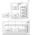
- FIG. 1 is a block diagram showing the functional configuration of a lighting control system according to an embodiment.
- FIG. 2 is a diagram (plan view) showing a space to which the lighting control system according to the embodiment is applied.
- the lighting device 20 is shown by a broken line circle
- the sensor 30 is shown by a solid line circle.
- the lighting control system 10 is a system that can individually provide a lighting environment to users located in a space 80 within a facility.
- the space 80 is, for example, an indoor space that is not partitioned by walls.
- the space 80 is, for example, a free-address office space.
- the space 80 is divided into a plurality of areas 81 each having seats (chairs 82 and desks 83), for example.
- the broken line (straight line) in FIG. 2 indicates a dividing line.
- the space 80 is divided into a matrix shape when viewed from above, but the method of dividing the space 80 is not particularly limited.
- the lighting control system 10 specifically includes a plurality of lighting devices 20, a plurality of sensors 30, a plurality of setting reception devices 40, and a control device 50.
- the lighting device 20, the sensor 30, and the setting reception device 40 are installed in each of the plurality of areas 81.
- a server device 60 is also illustrated in FIG. 1 .
- the lighting device 20 is installed on the ceiling of the space 80 and illuminates the space 80.
- the light source included in the illumination device 20 is realized by, for example, an LED (Light Emitting Diode) element, but may be realized by other light emitting elements such as a semiconductor laser, an organic EL (Electro-Luminescence), or an inorganic EL. .
- the lighting device 20 is, for example, a downlight, but may also be a base light, a ceiling light, a spotlight, or the like, and the specific aspect of the lighting device 20 is not particularly limited.
- the lighting device 20 can be dimmed and colored, and the brightness and color temperature of the light emitted by the lighting device 20 are controlled by the control device 50.
- the sensor 30 is an illuminance sensor that detects (senses) the illuminance in the area 81 where the sensor 30 is provided.
- the sensor 30 is installed, for example, on a desk 83.
- the sensor 30 transmits detection value information indicating a detection value that is a detection result of illuminance (also referred to as brightness) to the control device 50.
- the sensor 30 may be a sensor that detects the color temperature of light in the area 81.
- the setting reception device 40 is a device that allows a user to manually set a target value for the lighting environment (brightness, color temperature, etc.) of the area 81 where the user is located.
- the setting reception device 40 is, for example, a dedicated remote controller that corresponds to the lighting device 20 on a one-to-one basis.
- the setting reception device 40 transmits target value information indicating the target value set by the user to the control device 50.
- a mobile terminal such as a smartphone owned by the user and on which an application program is installed may be used as the setting reception device 40.
- the control device 50 is a controller that controls the plurality of lighting devices 20 installed in the space 80.
- the control device 50 is realized by, for example, an edge server installed in a facility including the space 80 or a cloud server installed outside the facility.
- the control device 50 includes a communication section 51, an information processing section 52, and a storage section 53.
- the communication unit 51 is a communication module (communication circuit) that allows the control device 50 to communicate with the plurality of lighting devices 20, the plurality of sensors 30, the plurality of setting reception devices 40, and the server device 60.
- the communication performed by the communication unit 51 is, for example, wired communication, but may also be wireless communication.
- the communication standard used for communication is also not particularly limited.
- the information processing unit 52 performs information processing regarding control of the lighting device 20 in the space 80.
- the information processing unit 52 is implemented, for example, by a microcomputer, but may also be implemented by a processor.
- the information processing unit 52 includes a detection unit 54, an acquisition unit 55, and a control unit 56 as functional components.
- the functions of the detection unit 54, the acquisition unit 55, and the control unit 56 are realized, for example, by a microcomputer, a processor, or the like constituting the information processing unit 52 executing a computer program stored in the storage unit 53. Detailed functions of each of the detection unit 54, acquisition unit 55, and control unit 56 will be described later.
- the storage unit 53 is a storage device that stores information necessary for the above information processing, computer programs executed by the information processing unit 52, and the like.
- the storage unit 53 is implemented, for example, by a HDD (Hard Disk Drive), but may also be implemented by a semiconductor memory or the like.
- the server device 60 is a computer that provides setting values for feedforward control (described later) to the control device 50.
- the server device 60 is realized, for example, by an edge server installed in a facility including the space 80 or a cloud server installed outside the facility.
- the server device 60 includes a machine learning model, and can determine (calculate) setting values for feedforward control using the machine learning model.
- the machine learning model here has a broad meaning, and the machine learning performed by the machine learning model includes various algorithms such as deep learning. In other words, there are no particular limitations on the specific algorithm for machine learning.
- the server device 60 will be described as an external server device that is not included in the lighting control system 10, but it may be included in the lighting control system 10. That is, the lighting control system 10 may include the server device 60.
- each of the plurality of areas 81 is provided with the lighting device 20, the sensor 30, and the setting reception device 40 in order to control the lighting environment in the area 81.
- the lighting environment specifically refers to brightness or color temperature, but in the following embodiments, a case where the lighting environment is brightness will be mainly described.
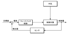
- FIG. 3 is a block diagram showing an overview of feedback control.
- the control device 50 makes the deviation between the detected value of the sensor 30 installed in the target area 81 and the target value zero (the detected value and the target value are equal).
- the setting value is calculated so that the lighting device 20 installed in the target area 81 is controlled based on the calculated setting value.
- the setting value here is the degree of light control (light control rate).
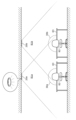
- FIG. 4 is a schematic diagram showing a target area 81 and an area 81 adjacent thereto.
- the target area 81 is described as a target area 81a
- the area 81 adjacent thereto is described as an adjacent area 81b.
- the detection ranges of the sensor 30a and the sensor 30b are illustrated as an image.
- the sensor 30a installed in the target area 81a receives not only the light emitted by the illumination device 20a installed in the target area 81a, but also the light emitted by the illumination device 20b installed in the adjacent area 81b. The emitted light also enters. Similarly, not only the light emitted by the lighting device 20b installed in the adjacent area 81b but also the light emitted by the lighting device 20a installed in the target area 81a enters the sensor 30b installed in the adjacent area 81b.
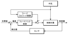
- FIG. 5 is a block diagram showing an overview of control of the lighting environment in the lighting control system 10. As shown in FIG. 5, the control device 50 (control unit 56) performs feedforward control on each of the plurality of lighting devices 20, and the deviation between the target value and detected value of the lighting environment after the feedforward control. Used in conjunction with feedback control to reduce
- the control device 50 acquires the feedforward control settings from the server device 60.
- the server device 60 includes a machine learning model that has learned feedforward control setting values for each of the plurality of lighting devices 20 based on learning data provided in advance from the control device 50 and the like.
- the above learning data includes the following information (a) to information (e).
- Information (a) to (c) is stored (registered) in the storage unit of the control device 50, for example, when the lighting control system 10 is installed.
- the information (d) can be acquired by the acquisition unit 55 from a plurality of sensors 30, for example.
- Information (e) indicates the degree of dimming at which the plurality of lighting devices 20 are currently emitting light, and this information is stored in the storage unit 53.
- the server device 60 detects each of the plurality of sensors 30 when the plurality of lighting devices 20 emits light according to the set value (information (e)). value can be learned. Specifically, the server device 60 (machine learning model) can output feedforward control setting values for each of the plurality of lighting devices 20.
- the detected value at the sensor 30 differs depending on the distance to the sensor 30 and the angle of incidence on the sensor 30.
- the brightness at the position of the sensor 30 is inversely proportional to the square of the distance from the lighting device 20 (light source).
- the brightness at the position of the sensor 30 is cos ⁇ times the brightness when the light arrives from the vertical direction, where ⁇ is the incident angle of the light with respect to the vertical direction.
- Information (b) and (c) are used to learn the correlation between the setting value of the lighting device 20 and the positional relationship between the lighting device 20 and the sensor 30.
- information (a) is specifically the coordinates of the plurality of lighting devices 20 and the plurality of sensors 30 in the space 80. Then, information (b) and (c) can also be calculated from information (a), and in this case, information (b) and (c) may be omitted. Information (a) to (c) can be rephrased as information indicating the positional relationship between the plurality of lighting devices 20 and the plurality of sensors 30.
- the learning data may include all of the information (a) to (e), and some of them may be omitted as necessary. Furthermore, the learning data may include information other than information (a) to (e).
- the lighting device 20 is task lighting (local lighting), and the ambient lighting (overall lighting) that illuminates the entire space 80 (the entire multiple areas 81) apart from the lighting device 20 Lighting) may be installed.
- the learning data may include information indicating the light emission state (setting value, etc.) of the ambient lighting.
- the learning data may include weather information at the point where the space 80 (the plurality of areas 81) is located. Specifically, the weather information is information on the amount of solar radiation related to external light that enters the space 80 from the outside. When the learning data includes this information, the data included in the request information described below also includes this information.
- the learning data may be data in a transient state (a state in which the brightness in each of the plurality of areas 81 has not converged and the target value and the detected value are different), or data in a steady state (in a state in which the brightness in each of the plurality of areas 81 is different).
- the data may be data in a state in which the brightness in each of the states has converged and the target value and the detected value are equal.
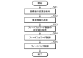
- FIG. 6 is a flowchart of example 1 of controlling the lighting environment of the lighting control system 10.
- the detection unit 54 of the control device 50 detects a change in the target brightness value in at least one of the plurality of areas 81 ( S11).
- the target value is changed, for example, by a user's manual operation on the setting reception device 40. Note that it is not essential that the target value be changed by the user; for example, the target value may be automatically changed based on predetermined schedule information.
- the acquisition unit 55 Upon detection of a change in the target value, the acquisition unit 55 transmits request information for requesting a feedforward control setting value to the server device 60 (S12). Specifically, the acquisition unit 55 uses the communication unit 51 to transmit the request information to the server device 60.
- the request information includes data, and in addition to the above-mentioned information (a) to (e), this data includes (f) a target value of the lighting environment (brightness) in each of the plurality of areas 81. This data can be said to be data related to the plurality of lighting devices 20 and the plurality of sensors 30. Note that the values of information (d) to (f) included in the request information are the latest values at the time when a change in the target value is detected.
- the server device 60 uses the data included in the request information and the machine learning model to compensate for the difference between the target value and the detected value in each of the plurality of areas 81. It is possible to calculate the feedforward control setting value (light control level) of The server device 60 transmits the calculated feedforward control setting values for each of the plurality of lighting devices 20 to the control device 50.
- the communication unit 51 of the control device 50 receives feedforward control setting values for each of the plurality of lighting devices 20 as a response to the request information.
- the acquisition unit 55 acquires the feedforward control setting values of each of the plurality of lighting devices 20 received by the communication unit 51 (S13).
- the feedforward control setting value is an example of control information for reducing the difference between the target value and the detected value in each of the plurality of areas 81.
- control unit 56 performs feedforward control on each of the plurality of lighting devices 20 using the acquired feedforward control settings (S14). Further, the control unit 56 performs feedback control based on the deviation between the target brightness value and the detected value in each of the plurality of areas 81 (S15). Specifically, the control unit 56 calculates a setting value for feedback control based on the deviation between the target brightness value and the detected value, and performs feedback control on each of the plurality of lighting devices 20 using the calculated setting value. I do.
- the lighting control system 10 updates the feedforward control setting value for each of the plurality of lighting devices 20 in response to a change in the target value of brightness in at least one of the plurality of areas 81. , performs feedback control for each of the plurality of lighting devices 20. Thereby, the occurrence of hunting and the like can be suppressed, and the brightness of each of the plurality of areas 81 can be brought close to the target value with high accuracy.
- server device 60 may use data included in the request information as learning data. That is, the server device 60 can update the machine learning model while providing the feedforward control setting value to the control device 50.
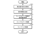
- FIG. 7 is a flowchart of a second example of controlling the lighting environment of the lighting control system 10.
- the detection unit 54 of the control device 50 detects a change in the detected value in at least one of the plurality of areas 81 (S21). Changes in the detected value occur due to, for example, external light entering the space 80.
- the acquisition unit 55 Upon detecting a change in the detection value, the acquisition unit 55 transmits request information for requesting a feedforward control setting value to the server device 60 (S22). Specifically, the acquisition unit 55 uses the communication unit 51 to transmit the request information to the server device 60.
- the request information includes data, and this data includes the information (a) to (f) described above. Note that the values of information (d) to (f) included in the request information are the latest values at the time when a change in the detection value is detected.
- the server device 60 uses the data included in the request information and the machine learning model to compensate for the difference between the target value and the detected value in each of the plurality of areas 81. It is possible to calculate the feedforward control setting value (light control level) of The server device 60 transmits the calculated feedforward control setting values for each of the plurality of lighting devices 20 to the control device 50.
- the communication unit 51 of the control device 50 receives feedforward control setting values for each of the plurality of lighting devices 20 as a response to the request information.
- the acquisition unit 55 acquires feedforward control setting values for each of the plurality of lighting devices 20 (S23). Specifically, the acquisition unit 55 uses the communication unit 51 to acquire (receive) feedforward control setting values for each of the plurality of lighting devices 20 from the server device 60 .
- the feedforward control setting value is an example of control information.
- control unit 56 performs feedforward control on each of the plurality of lighting devices 20 using the acquired feedforward control settings (S24). Further, the control unit 56 performs feedback control based on the deviation between the target brightness value and the detected value in each of the plurality of areas 81 (S25). Specifically, the control unit 56 calculates a setting value for feedback control based on the deviation between the target brightness value and the detected value, and performs feedback control on each of the plurality of lighting devices 20 using the calculated setting value. I do.
- the lighting control system 10 adjusts feedforward control settings for each of the plurality of lighting devices 20 upon a change in the detected brightness value in at least one of the plurality of areas 81 (the plurality of sensors 30). After updating, feedback control is performed for each of the plurality of lighting devices 20. Thereby, the occurrence of hunting and the like can be suppressed, and the brightness of each of the plurality of areas 81 can be brought close to the target value with high accuracy.
- server device 60 may use data included in the request information as learning data. That is, the server device 60 can update the machine learning model while providing the feedforward control setting value to the control device 50.
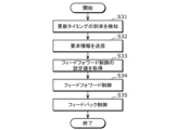
- FIG. 8 is a flowchart of a third example of controlling the lighting environment of the lighting control system 10.
- the feedforward control setting value is periodically updated at update timings that occur at predetermined time intervals.
- the detection unit 54 of the control device 50 detects that the update timing has arrived (S31). Note that the predetermined time interval is appropriately determined empirically or experimentally.
- the acquisition unit 55 transmits request information for requesting the feedforward control setting value to the server device 60 (S32). Specifically, the acquisition unit 55 uses the communication unit 51 to transmit the request information to the server device 60.
- the request information includes data, and this data includes the information (a) to (f) described above. Note that the values of information (d) to (f) included in the request information are the latest values at the time when the arrival of the update timing is detected.
- the server device 60 uses the data included in the request information and the machine learning model to compensate for the difference between the target value and the detected value in each of the plurality of areas 81. It is possible to calculate the feedforward control setting value (light control level) of The server device 60 transmits the calculated feedforward control setting values for each of the plurality of lighting devices 20 to the control device 50.
- the communication unit 51 of the control device 50 receives feedforward control setting values for each of the plurality of lighting devices 20 as a response to the request information.
- the acquisition unit 55 acquires feedforward control setting values for each of the plurality of lighting devices 20 (S33). Specifically, the acquisition unit 55 uses the communication unit 51 to acquire (receive) feedforward control setting values for each of the plurality of lighting devices 20 from the server device 60 .
- the feedforward control setting value is an example of control information.
- control unit 56 performs feedforward control on each of the plurality of lighting devices 20 using the acquired feedforward control settings (S34). Further, the control unit 56 performs feedback control based on the deviation between the target brightness value and the detected value in each of the plurality of areas 81 (S35). Specifically, the control unit 56 calculates a setting value for feedback control based on the deviation between the target brightness value and the detected value, and performs feedback control on each of the plurality of lighting devices 20 using the calculated setting value. I do.
- the lighting control system 10 updates the feedforward control setting values for each of the plurality of lighting devices 20 upon arrival of the update timing, and then performs feedback control for each of the plurality of lighting devices 20. conduct. Thereby, the occurrence of hunting and the like can be suppressed, and the brightness of each of the plurality of areas 81 can be brought close to the target value with high accuracy.
- server device 60 may use data included in the request information as learning data. That is, the server device 60 can update the machine learning model while providing the feedforward control setting value to the control device 50.
- the lighting control system 10 may operate in a learning mode to provide learning data to the server device 60.
- the learning mode operation is an operation for generating learning data.
- the lighting control system 10 operates as follows, for example.
- the control unit 56 of the control device 50 selects one of the plurality of lighting devices 20 as a target lighting device.
- the control unit 56 causes the target lighting device to emit light at a first setting value (for example, dimming intensity 50%), and causes the non-target lighting devices (all lighting devices 20 other than the target lighting device) to emit light at a second setting. Light is emitted at a certain value (for example, dimming level 20%).
- the control unit 56 generates learning data (data including the above information (a) to (e)).
- the control unit 56 repeats the above operation by changing the target lighting device. When all of the plurality of lighting devices 20 are selected once as target lighting devices, the learning mode operation ends. Note that the control unit 56 may further repeat the operation in the learning mode by changing at least one of the first set value and the second set value. Learning data generated during operation in the learning mode is provided from the control device 50 to the server device 60 as appropriate.
- the lighting control system 10 aims to expand the variation of learning data by acquiring the detection values of each of the plurality of sensors 30 when the setting values of each of the plurality of lighting devices 20 are forcibly changed. I can do it.
- the order in which the plurality of lighting devices 20 are selected as target lighting devices is not particularly limited.
- the lighting device 20 in the center may be selected as the target lighting device first, or the lighting devices 20 located at the corners may be It may be selected as the target lighting device first.
- the server device 60 uses not only learning data based on the lighting conditions in the space 80 but also learning data based on the lighting conditions in other spaces to learn the setting values for feedforward control.
- the server device 60 uses the same Learning data based on the lighting conditions on the second floor (another space) within the facility may be collected.
- the second floor is a different floor from the first floor.
- the server device 60 may collect learning data based on lighting conditions on three or more floors.
- the server device 60 can improve the accuracy of calculating the feedforward control setting value by collecting learning data based on the lighting conditions on two or more floors within the same facility.
- the server device 60 stores the learning data based on the lighting state within the first facility (space 80). Learning data based on the lighting conditions within the two facilities (other spaces) may also be collected.
- the second facility is a facility different from the first facility.
- the server device 60 may collect learning data based on lighting conditions at three or more facilities.
- the server device 60 can improve the calculation accuracy of the feedforward control setting value by collecting learning data based on the lighting conditions in each of the spaces in two or more facilities.
- the lighting control system 10 can be applied to control a lighting environment including at least one of brightness, color temperature, light distribution, and the like.
- the arrangement of the plurality of lighting devices 20 and the arrangement of the plurality of sensors 30 in the above embodiment are merely examples.
- the plurality of lighting devices 20 may be arranged in any manner as long as they can individually illuminate the plurality of adjacent areas 81.
- the plurality of sensors 30 may be arranged in any manner as long as they can individually sense the detected values of the lighting environment in the plurality of areas 81.
- the target value of the lighting environment in each of the plurality of areas 81 is set (changed) by the user located in the space 80, but it is not essential that the target value is set by the user.
- the target value may be set by an administrator located outside the space. Further, the target value may be automatically changed based on predetermined schedule information.
- the lighting control system 10 includes a plurality of lighting devices 20 for individually illuminating a plurality of adjacent areas 81, each of which has a set target value for its lighting environment; By transmitting data related to the plurality of sensors 30 for individually sensing the detection values of the lighting environment in the plurality of areas 81 to the server device 60, the difference between the target value and the detection value in each of the plurality of areas 81 can be calculated. It includes an acquisition unit 55 that acquires control information for reduction from the server device 60, and a control unit 56 that controls the plurality of lighting devices 20 using the acquired control information.
- Such a lighting control system 10 can bring the lighting environment of the plurality of areas 81, where changes in the lighting environment mutually influence each other, closer to the target.
- control unit 56 uses both feedforward control and feedback control for each of the plurality of lighting devices 20, and the control information includes a set value of the feedforward control for each of the plurality of lighting devices 20. This is the information shown.
- the lighting control system 10 In such a lighting control system 10, most of the control is performed by feedforward control, and the remaining slight deviation between the target value and the detected value can be reduced by feedback control.
- the lighting control system 10 can suppress the occurrence of hunting and the like.
- the data includes information indicating the positional relationship between the plurality of lighting devices 20 and the plurality of sensors 30.
- Such a lighting control system 10 can acquire control information that takes into account the positional relationships between the plurality of lighting devices 20 and the plurality of sensors 30. In other words, the lighting control system 10 can control the plurality of lighting devices 20 in consideration of the positional relationship between the plurality of lighting devices 20 and the plurality of sensors 30.
- the information indicating the positional relationship includes information indicating the distance between each of the plurality of lighting devices 20 and each of the plurality of sensors 30, and the incidence of light emitted by each of the plurality of lighting devices 20 on each of the plurality of sensors 30. Contains information indicating corners.
- Such a lighting control system 10 can acquire control information that takes into account the distance and the angle of incidence. In other words, the lighting control system 10 can control the plurality of lighting devices 20 in consideration of the distance and the angle of incidence.
- the acquisition unit 55 acquires control information from the server device 60 by transmitting data to the server device 60 when the target value of the lighting environment in at least one of the plurality of areas 81 is changed. do.
- Such a lighting control system 10 can acquire (update) control information in response to a change in the target value of the lighting environment.
- the acquisition unit 55 acquires control information from the server device 60 by transmitting data to the server device 60 when the detected value of the lighting environment in at least one of the plurality of areas 81 changes. .
- Such a lighting control system 10 can acquire (update) control information in response to a change in the detected value of the lighting environment.
- the acquisition unit 55 acquires control information from the server device 60 by transmitting data to the server device 60 at predetermined time intervals.
- Such a lighting control system 10 can acquire (update) control information at predetermined time intervals.
- the data includes at least one of information indicating the light emission state of the overall illumination that illuminates the entire plurality of areas 81 and weather information at the points where the plurality of areas 81 are located.
- Such a lighting control system 10 can acquire control information that takes into consideration at least one of the light emission state of the overall lighting and weather information.
- the lighting control system 10 can control the plurality of lighting devices 20 in consideration of at least one of the light emission state of the overall lighting and weather information.
- the server device 60 includes a machine learning model that outputs control information based on the received data.
- the lighting control system 10 controls only a target lighting device among the plurality of lighting devices 20 to emit light at a setting value that is different from other lighting devices. Learning data is generated by repeating the process while changing the target lighting device.
- Such a lighting control system 10 can increase the variation of learning data.
- the plurality of areas 81 are provided on the first floor within the facility.
- the server device 60 collects learning data based on the lighting condition on the second floor in the facility in addition to learning data based on the lighting condition on the first floor.
- Such a server device 60 can improve the accuracy of control information by collecting learning data based on lighting conditions on multiple floors within the same facility.
- the server device 60 collects learning data based on the lighting condition in the second facility in addition to learning data based on the lighting condition in the first facility.
- Such a server device 60 can improve the accuracy of control information by collecting learning data based on the lighting conditions in each of the spaces within a plurality of facilities.
- the lighting control method executed by a computer such as the lighting control system 10 includes a plurality of areas 81 for each of which a target value of the lighting environment is determined, and a plurality of areas 81 for individually illuminating a plurality of adjacent areas 81. target values in each of the plurality of areas 81 by transmitting data related to the lighting device 20 and the plurality of sensors 30 for individually sensing detected values of the lighting environment in the plurality of areas 81 to the server device 60. and a control step of controlling the plurality of lighting devices 20 using the acquired control information.
- Such a lighting control method can bring the lighting environment of the plurality of areas 81, where changes in the lighting environment mutually influence each other, closer to the target.
- the lighting control system was realized by a plurality of devices.
- the components (particularly functional components) included in the lighting control system may be distributed to the plurality of devices in any manner.
- the lighting control system may also be implemented as a single device.
- the lighting control system may be implemented as a single device corresponding to the control device.
- the order of processing described in the above embodiment is an example.
- the order of multiple processes may be changed, and multiple processes may be executed in parallel.
- the processing executed by a specific processing unit may be executed by another processing unit.
- each component may be realized by executing a software program suitable for each component.
- Each component may be realized by a program execution unit such as a CPU or a processor reading and executing a software program recorded on a recording medium such as a hard disk or a semiconductor memory.
- each component may be realized by hardware.
- each component may be a circuit (or integrated circuit). These circuits may constitute one circuit as a whole, or may be separate circuits. Further, each of these circuits may be a general-purpose circuit or a dedicated circuit.
- the general or specific aspects of the present invention may be implemented in a system, device, method, integrated circuit, computer program, or computer-readable recording medium such as a CD-ROM.
- the present invention may be realized by any combination of a system, an apparatus, a method, an integrated circuit, a computer program, and a recording medium.
- the present invention may be implemented as a lighting control method executed by a computer such as a lighting control system, or may be implemented as a program for causing a computer to execute such a lighting control method.
- the present invention may be realized as a computer-readable non-transitory recording medium on which such a program is recorded.
Landscapes
- Circuit Arrangement For Electric Light Sources In General (AREA)
Abstract
Description
[構成]
まず、実施の形態に係る照明制御システムの構成について説明する。図1は、実施の形態に係る照明制御システムの機能構成を示すブロック図である。図2は、実施の形態に係る照明制御システムが適用される空間を示す図(平面図)である。なお、図2では、照明装置20が破線の円で示され、センサ30が実線の円で示されている。
上述のように複数のエリア81のそれぞれには、当該エリア81における照明環境を制御するために、照明装置20、センサ30、及び、設定受付装置40が設けられている。照明環境は、具体的には、明るさまたは色温度などを意味するが、以下の実施の形態では主として照明環境が明るさである場合について説明する。
そこで、制御装置50は、目標値の変化、及び、外光の入射等の外乱による影響を考慮したフィードフォワード制御によって大部分の制御を行い、オーバーシュートの発生、及び、振動的な応答の発生を抑制する。さらに、制御装置50は、残りのわずかな目標値と検出値との偏差の低減をフィードバック制御によって実現する。図5は、照明制御システム10における照明環境の制御の概要を示すブロック図である。図5に示されるように、制御装置50(制御部56)は、複数の照明装置20のそれぞれに対して、フィードフォワード制御と、当該フィードフォワード制御後の照明環境の目標値及び検出値の偏差を低減するフィードバック制御とを併用する。
(b)複数の照明装置20のそれぞれと複数のセンサ30それぞれとの距離を示す情報
(c)複数の照明装置20それぞれが発する光の複数のセンサ30のそれぞれに対する入射角を示す情報
(d)複数のセンサ30のそれぞれにおける検出値
(e)複数の照明装置20のそれぞれの設定値
次に、照明制御システム10の照明環境の制御について、より具体的に説明する。図6は、照明制御システム10の照明環境の制御例1のフローチャートである。
次に、照明制御システム10の照明環境の制御例2について説明する。図7は、照明制御システム10の照明環境の制御例2のフローチャートである。
次に、照明制御システム10の照明環境の制御例3について説明する。図8は、照明制御システム10の照明環境の制御例3のフローチャートである。
また、照明制御システム10は、学習データをサーバ装置60へ提供するための学習モードの動作を行ってもよい。学習モードの動作は、言い換えれば、学習データを生成するための動作である。学習モードにおいて、照明制御システム10は、例えば、以下のように動作する。
上記実施の形態では、複数のエリア81それぞれの明るさが制御される例について説明したが、明るさに代えて色温度または配光などが制御されてもよい。照明制御システム10は、明るさ、色温度、及び、配光などの少なくとも1つを含む照明環境の制御に適用することができる。
以上説明したように、照明制御システム10は、各々に照明環境の目標値が定められた複数のエリア81であって隣接する複数のエリア81を個別に照明するための複数の照明装置20と、複数のエリア81における照明環境の検出値を個別にセンシングするための複数のセンサ30とに関連するデータをサーバ装置60へ送信することにより、複数のエリア81それぞれにおける目標値及び検出値の差を低減するための制御情報をサーバ装置60から取得する取得部55と、取得された制御情報を用いて複数の照明装置20を制御する制御部56とを備える。
以上、実施の形態について説明したが、本発明は、上記実施の形態に限定されるものではない。
20、20a、20b 照明装置
30、30a、30b センサ
40 設定受付装置
50 制御装置
51 通信部
52 情報処理部
53 記憶部
54 検知部
55 取得部
56 制御部
60 サーバ装置(外部サーバ装置)
80 空間
81 エリア
81a 対象のエリア
81b 隣接エリア
82 椅子
83 机
Claims (12)
- 各々に照明環境の目標値が定められた複数のエリアであって隣接する前記複数のエリアを個別に照明するための複数の照明装置と、前記複数のエリアにおける照明環境の検出値を個別にセンシングするための複数のセンサとに関連するデータを外部サーバ装置へ送信することにより、前記複数のエリアそれぞれにおける前記目標値及び前記検出値の差を低減するための制御情報を前記外部サーバ装置から取得する取得部と、
取得された前記制御情報を用いて前記複数の照明装置を制御する制御部とを備える
照明制御システム。 - 前記制御部は、前記複数の照明装置のそれぞれに対して、フィードフォワード制御と、フィードバック制御とを併用し、
前記制御情報は、前記複数の照明装置それぞれに対する前記フィードフォワード制御の設定値を示す情報である
請求項1に記載の照明制御システム。 - 前記データには、前記複数の照明装置及び前記複数のセンサの位置関係を示す情報が含まれる
請求項1に記載の照明制御システム。 - 前記位置関係を示す情報には、前記複数の照明装置それぞれと前記複数のセンサそれぞれとの距離を示す情報、及び、前記複数の照明装置それぞれが発する光の前記複数のセンサそれぞれに対する入射角を示す情報が含まれる
請求項3に記載の照明制御システム。 - 前記取得部は、前記複数のエリアの少なくとも1つにおける前記目標値が変更されたことを契機に前記データを前記外部サーバ装置へ送信することにより、前記制御情報を前記外部サーバ装置から取得する
請求項1~4のいずれか1項に記載の照明制御システム。 - 前記取得部は、前記複数のエリアの少なくとも1つにおける前記検出値が変化したことを契機に前記データを前記外部サーバ装置へ送信することにより、前記制御情報を前記外部サーバ装置から取得する
請求項1~4のいずれか1項に記載の照明制御システム。 - 前記取得部は、所定の時間間隔で前記データを前記外部サーバ装置へ送信することにより、前記制御情報を前記外部サーバ装置から取得する
請求項1~4のいずれか1項に記載の照明制御システム。 - 前記データには、前記複数のエリア全体を照明する全体照明の発光状態を示す情報、及び、前記複数のエリアが位置する地点における気象情報の少なくとも一方が含まれる
請求項1~4のいずれか1項に記載の照明制御システム。 - 前記外部サーバ装置は、受信した前記データに基づいて前記制御情報を出力する機械学習モデルを備え、
前記照明制御システムは、前記機械学習モデルへ学習データを提供するための学習モードの動作において、前記複数の照明装置のうち対象の照明装置だけを他の照明装置と異なる設定値で発光させる制御を、前記対象の照明装置を変更しながら繰り返すことで、学習データを生成する
請求項1~4のいずれか1項に記載の照明制御システム。 - 前記複数のエリアは、施設内の第1フロアに設けられ、
前記外部サーバ装置は、前記第1フロアにおける照明状態に基づく学習データに加えて、前記施設内の第2フロアにおける照明状態に基づく学習データを収集する
請求項9に記載の照明制御システム。 - 前記複数のエリアは、第1施設内に設けられ、
前記外部サーバ装置は、前記第1施設内における照明状態に基づく学習データに加えて、第2施設内の照明状態に基づく学習データを収集する
請求項9に記載の照明制御システム。 - コンピュータによって実行される照明制御方法であって、
各々に照明環境の目標値が定められた複数のエリアであって隣接する前記複数のエリアを個別に照明するための複数の照明装置と、前記複数のエリアにおける照明環境の検出値を個別にセンシングするための複数のセンサとに関連するデータを外部サーバ装置へ送信することにより、前記複数のエリアそれぞれにおける前記目標値及び前記検出値の差を低減するための制御情報を前記外部サーバ装置から取得する取得ステップと、
取得された前記制御情報を用いて前記複数の照明装置を制御する制御ステップとを含む
照明制御方法。
Priority Applications (3)
| Application Number | Priority Date | Filing Date | Title |
|---|---|---|---|
| JP2024514853A JP7664560B2 (ja) | 2022-04-12 | 2023-03-10 | 照明制御システム、及び、照明制御方法 |
| EP23788091.9A EP4510780A4 (en) | 2022-04-12 | 2023-03-10 | LIGHTING CONTROL SYSTEM AND LIGHTING CONTROL METHOD |
| CN202380027023.9A CN118844115A (zh) | 2022-04-12 | 2023-03-10 | 照明控制系统和照明控制方法 |
Applications Claiming Priority (2)
| Application Number | Priority Date | Filing Date | Title |
|---|---|---|---|
| JP2022065839 | 2022-04-12 | ||
| JP2022-065839 | 2022-04-12 |
Publications (1)
| Publication Number | Publication Date |
|---|---|
| WO2023199669A1 true WO2023199669A1 (ja) | 2023-10-19 |
Family
ID=88329392
Family Applications (1)
| Application Number | Title | Priority Date | Filing Date |
|---|---|---|---|
| PCT/JP2023/009275 Ceased WO2023199669A1 (ja) | 2022-04-12 | 2023-03-10 | 照明制御システム、及び、照明制御方法 |
Country Status (4)
| Country | Link |
|---|---|
| EP (1) | EP4510780A4 (ja) |
| JP (1) | JP7664560B2 (ja) |
| CN (1) | CN118844115A (ja) |
| WO (1) | WO2023199669A1 (ja) |
Cited By (1)
| Publication number | Priority date | Publication date | Assignee | Title |
|---|---|---|---|---|
| WO2024127867A1 (ja) * | 2022-12-15 | 2024-06-20 | パナソニックIpマネジメント株式会社 | 空調制御システム、及び、制御方法 |
Citations (3)
| Publication number | Priority date | Publication date | Assignee | Title |
|---|---|---|---|---|
| JP2001015270A (ja) * | 1999-06-30 | 2001-01-19 | Matsushita Electric Works Ltd | 調光制御システム |
| JP2019106300A (ja) | 2017-12-13 | 2019-06-27 | アール・ビー・コントロールズ株式会社 | Led照明装置 |
| JP2020053359A (ja) * | 2018-09-28 | 2020-04-02 | 東芝ライテック株式会社 | 情報処理システム |
Family Cites Families (2)
| Publication number | Priority date | Publication date | Assignee | Title |
|---|---|---|---|---|
| WO2019023760A1 (en) * | 2017-08-03 | 2019-02-07 | Vaboss Pty Ltd | METHOD, SYSTEM AND CONTROL DEVICE |
| US10609784B1 (en) * | 2018-10-25 | 2020-03-31 | Verizon Patent And Licensing Inc. | Causing a brightness level of a light to change |
-
2023
- 2023-03-10 CN CN202380027023.9A patent/CN118844115A/zh active Pending
- 2023-03-10 JP JP2024514853A patent/JP7664560B2/ja active Active
- 2023-03-10 EP EP23788091.9A patent/EP4510780A4/en active Pending
- 2023-03-10 WO PCT/JP2023/009275 patent/WO2023199669A1/ja not_active Ceased
Patent Citations (3)
| Publication number | Priority date | Publication date | Assignee | Title |
|---|---|---|---|---|
| JP2001015270A (ja) * | 1999-06-30 | 2001-01-19 | Matsushita Electric Works Ltd | 調光制御システム |
| JP2019106300A (ja) | 2017-12-13 | 2019-06-27 | アール・ビー・コントロールズ株式会社 | Led照明装置 |
| JP2020053359A (ja) * | 2018-09-28 | 2020-04-02 | 東芝ライテック株式会社 | 情報処理システム |
Non-Patent Citations (1)
| Title |
|---|
| See also references of EP4510780A4 |
Cited By (1)
| Publication number | Priority date | Publication date | Assignee | Title |
|---|---|---|---|---|
| WO2024127867A1 (ja) * | 2022-12-15 | 2024-06-20 | パナソニックIpマネジメント株式会社 | 空調制御システム、及び、制御方法 |
Also Published As
| Publication number | Publication date |
|---|---|
| EP4510780A1 (en) | 2025-02-19 |
| JPWO2023199669A1 (ja) | 2023-10-19 |
| JP7664560B2 (ja) | 2025-04-18 |
| CN118844115A (zh) | 2024-10-25 |
| EP4510780A4 (en) | 2025-08-06 |
Similar Documents
| Publication | Publication Date | Title |
|---|---|---|
| Pandharipande et al. | Smart indoor lighting systems with luminaire-based sensing: A review of lighting control approaches | |
| US9832848B2 (en) | Lighting system and method for controlling lighting system | |
| JP5777716B2 (ja) | 照明調光率決定装置 | |
| KR20110118693A (ko) | 주변 조명 조건들에 반응하는 조명 제어 시스템 | |
| RU2013148930A (ru) | Устройство и способ управления освещенностью от множества источников света | |
| US20180242434A1 (en) | Lighting control system and lighting control device used therefor | |
| CN103444267A (zh) | 信息处理装置、图像传感器装置及程序 | |
| US20160234906A1 (en) | Lighting system and method for controlling lighting system | |
| JP6839103B2 (ja) | 照明システム内の装置を設定するための方法 | |
| WO2023199669A1 (ja) | 照明制御システム、及び、照明制御方法 | |
| JP6704193B2 (ja) | 照明制御装置 | |
| JP2014186960A (ja) | 照明制御システム及び照明制御方法 | |
| JP7183570B2 (ja) | 照明制御システム | |
| KR101846495B1 (ko) | 에너지 절감을 위한 무선네트워크 기반 led 조명 제어 및 운영 방법 | |
| JP2013004311A (ja) | 照明制御システム | |
| JP6739055B2 (ja) | 照明制御装置及び照明システム | |
| JP6917922B2 (ja) | 照明制御システム、照明器具、照明制御方法及びコンピュータプログラム | |
| CN113647057A (zh) | 利用预测事件操作的网络系统 | |
| KR20120128385A (ko) | 고 에너지효율 조명 시스템 및 그 제어방법 | |
| JP6104102B2 (ja) | 照明制御装置、照明制御方法、及びプログラム | |
| KR20130076000A (ko) | 배광 정보를 갖는 스마트 조명 장치 및 이를 이용한 조명 제어 시스템 | |
| CN113826443A (zh) | 一种用于控制照明系统的多个照明单元的控制器及其方法 | |
| US20260082472A1 (en) | Control terminal, device control system, control method, and recording medium | |
| JP7668466B2 (ja) | 照明システム及び照明制御方法 | |
| JP6665626B2 (ja) | 照明制御装置、照明システム及び照明制御方法 |
Legal Events
| Date | Code | Title | Description |
|---|---|---|---|
| 121 | Ep: the epo has been informed by wipo that ep was designated in this application |
Ref document number: 23788091 Country of ref document: EP Kind code of ref document: A1 |
|
| ENP | Entry into the national phase |
Ref document number: 2024514853 Country of ref document: JP Kind code of ref document: A |
|
| WWE | Wipo information: entry into national phase |
Ref document number: 202380027023.9 Country of ref document: CN |
|
| WWE | Wipo information: entry into national phase |
Ref document number: 18854801 Country of ref document: US |
|
| WWE | Wipo information: entry into national phase |
Ref document number: 2023788091 Country of ref document: EP |
|
| NENP | Non-entry into the national phase |
Ref country code: DE |
|
| ENP | Entry into the national phase |
Ref document number: 2023788091 Country of ref document: EP Effective date: 20241112 |