WO2023199810A1 - ロータリーダンパ及びバルブ並びにバルブの摩耗によるロータリーダンパのトルクの低下を防止する方法 - Google Patents
ロータリーダンパ及びバルブ並びにバルブの摩耗によるロータリーダンパのトルクの低下を防止する方法 Download PDFInfo
- Publication number
- WO2023199810A1 WO2023199810A1 PCT/JP2023/014052 JP2023014052W WO2023199810A1 WO 2023199810 A1 WO2023199810 A1 WO 2023199810A1 JP 2023014052 W JP2023014052 W JP 2023014052W WO 2023199810 A1 WO2023199810 A1 WO 2023199810A1
- Authority
- WO
- WIPO (PCT)
- Prior art keywords
- valve
- oil
- wear
- gap
- oil chamber
- Prior art date
- Legal status (The legal status is an assumption and is not a legal conclusion. Google has not performed a legal analysis and makes no representation as to the accuracy of the status listed.)
- Ceased
Links
Images










Classifications
-
- F—MECHANICAL ENGINEERING; LIGHTING; HEATING; WEAPONS; BLASTING
- F16—ENGINEERING ELEMENTS AND UNITS; GENERAL MEASURES FOR PRODUCING AND MAINTAINING EFFECTIVE FUNCTIONING OF MACHINES OR INSTALLATIONS; THERMAL INSULATION IN GENERAL
- F16F—SPRINGS; SHOCK-ABSORBERS; MEANS FOR DAMPING VIBRATION
- F16F9/00—Springs, vibration-dampers, shock-absorbers, or similarly-constructed movement-dampers using a fluid or the equivalent as damping medium
- F16F9/10—Springs, vibration-dampers, shock-absorbers, or similarly-constructed movement-dampers using a fluid or the equivalent as damping medium using liquid only; using a fluid of which the nature is immaterial
- F16F9/14—Devices with one or more members, e.g. pistons, vanes, moving to and fro in chambers and using throttling effect
- F16F9/145—Devices with one or more members, e.g. pistons, vanes, moving to and fro in chambers and using throttling effect involving only rotary movement of the effective parts
-
- F—MECHANICAL ENGINEERING; LIGHTING; HEATING; WEAPONS; BLASTING
- F16—ENGINEERING ELEMENTS AND UNITS; GENERAL MEASURES FOR PRODUCING AND MAINTAINING EFFECTIVE FUNCTIONING OF MACHINES OR INSTALLATIONS; THERMAL INSULATION IN GENERAL
- F16F—SPRINGS; SHOCK-ABSORBERS; MEANS FOR DAMPING VIBRATION
- F16F2222/00—Special physical effects, e.g. nature of damping effects
- F16F2222/12—Fluid damping
-
- F—MECHANICAL ENGINEERING; LIGHTING; HEATING; WEAPONS; BLASTING
- F16—ENGINEERING ELEMENTS AND UNITS; GENERAL MEASURES FOR PRODUCING AND MAINTAINING EFFECTIVE FUNCTIONING OF MACHINES OR INSTALLATIONS; THERMAL INSULATION IN GENERAL
- F16F—SPRINGS; SHOCK-ABSORBERS; MEANS FOR DAMPING VIBRATION
- F16F2232/00—Nature of movement
- F16F2232/02—Rotary
-
- F—MECHANICAL ENGINEERING; LIGHTING; HEATING; WEAPONS; BLASTING
- F16—ENGINEERING ELEMENTS AND UNITS; GENERAL MEASURES FOR PRODUCING AND MAINTAINING EFFECTIVE FUNCTIONING OF MACHINES OR INSTALLATIONS; THERMAL INSULATION IN GENERAL
- F16F—SPRINGS; SHOCK-ABSORBERS; MEANS FOR DAMPING VIBRATION
- F16F2236/00—Mode of stressing of basic spring or damper elements or devices incorporating such elements
- F16F2236/08—Torsion
- F16F2236/085—Torsion the spring being annular
Definitions
- the present invention relates to a rotary damper, a valve, and a method for preventing a decrease in the torque of the rotary damper due to wear of the valve.
- a first end surface that faces a first surface that closes one end of the oil chamber a second end surface that faces a second surface that closes the other end of the oil chamber, and a back surface that opposes the curved surface of the oil chamber.
- a valve part that closes an oil passage formed between the oil passage and the rotor and when the valve part closes the oil passage, the oil injected into the oil chamber is prevented from flowing backward through the oil passage.
- FIGS. 3 to 7 of International Publication No. 2012/141242 show a first end surface opposite to a first surface (bottom surface of plug 30) that closes one end of the oil chamber (chamber 71 and chamber 72); A second end surface that faces the second surface that closes the other end of the oil chamber (the upper surface of the end wall 11), a back surface that opposes the curved surface of the oil chamber (the inner circumferential surface of the peripheral wall 12), and the rotor. It has a valve part (protrusion part 84b) that closes the oil passage (first groove 81) formed in the oil passage, and when the valve part closes the oil passage, the oil injected into the oil chamber passes through the oil passage.
- a rotary damper is disclosed that includes a valve (valve body 84) that prevents reverse flow through the rotary damper.
- the rotor or housing rotates while the first end surface of the valve contacts the first surface of the oil chamber and the back surface of the valve contacts the curved surface of the oil chamber, or the rotor or housing rotates while the first end surface of the valve contacts the first surface of the oil chamber.
- the problem is that the rotor or housing rotates while the two end surfaces are in contact with the second surface of the oil chamber and the back surface of the valve is in contact with the curved surface of the oil chamber, which causes the valve to wear, resulting in a decrease in torque. was there.
- the problem to be solved by the present invention is to prevent the torque of the rotary damper from decreasing due to valve wear.
- the present invention provides a rotary damper, a valve, and a method for preventing a decrease in torque of the rotary damper due to valve wear.
- 1. a first end surface that faces a first surface that closes one end of the oil chamber; a second end surface that faces a second surface that closes the other end of the oil chamber; a back surface that opposes the curved surface of the oil chamber; It has a valve part that closes an oil passage formed between the rotor and the oil passage, and the valve part closes the oil passage to prevent oil injected into the oil chamber from flowing backward through the oil passage.
- the bulb has unevenness on the back surface,
- the concave portion of the unevenness forms a gap with the curved surface,
- the cross-sectional area of the gap is reduced due to wear of the convex portion of the unevenness,
- a rotary damper characterized in that the function of the valve portion is not impaired by wear of the convex portion.
- a first end surface that faces a first surface that closes one end of the oil chamber; a second end surface that faces a second surface that closes the other end of the oil chamber; a back surface that opposes the curved surface of the oil chamber; It has a valve part that closes an oil passage formed between the rotor and the oil passage, and the valve part closes the oil passage to prevent oil injected into the oil chamber from flowing backward through the oil passage.
- the bulb has unevenness on the back surface,
- the concave portion of the unevenness forms a gap with the curved surface, the oil has a viscosity sufficient to prevent torque from decreasing due to the gap;
- the cross-sectional area of the gap is reduced due to wear of the convex portion of the unevenness,
- a rotary damper characterized in that the function of the valve portion is not impaired by wear of the convex portion. 3.
- a valve for a rotary damper The valve has a first end surface that faces a first surface that closes one end of the oil chamber, a second end surface that faces a second surface that closes the other end of the oil chamber, and a second end surface that faces a curved surface of the oil chamber.
- It has a back surface, a valve portion that closes an oil passage formed between the rotor and the back surface, and an unevenness formed on the back surface, and when the valve portion closes the oil passage, the oil injected into the oil chamber is injected into the oil chamber. Prevents backflow through the oil path, The concave portion of the unevenness forms a gap with the curved surface, The cross-sectional area of the gap is reduced due to wear of the convex portion of the unevenness, A valve characterized in that the function of the valve portion is not impaired by wear of the convex portion. 4.
- a method for preventing a decrease in rotary damper torque due to valve wear comprising:
- the valve includes a first end surface facing a first surface that closes one end of the oil chamber, a second end surface facing a second surface that closes the other end of the oil chamber, and a second end surface facing a curved surface of the oil chamber.
- a valve portion that closes an oil passage formed between the rotor and the rotor, and an unevenness formed on the back surface, and when the valve portion closes the oil passage, oil is injected into the oil chamber.
- the recessed portion of the unevenness forms a gap with the curved surface, and the cross-sectional area of the gap is reduced by wear of the convexed portion of the unevenness, and the valve portion
- the function of the protrusion is not impaired by wear of the convex part, A reduction in torque due to an enlargement of the gap between the second end face and the second surface due to wear of the first end face or an enlargement of the gap between the first end face and the first face due to wear of the second end face. , by reducing the cross-sectional area of the gap due to wear of the convex portion. 5.
- a method for preventing a decrease in rotary damper torque due to valve wear comprising:
- the valve includes a first end surface facing a first surface that closes one end of the oil chamber, a second end surface facing a second surface that closes the other end of the oil chamber, and a second end surface facing a curved surface of the oil chamber.
- a valve portion that closes an oil passage formed between the rotor and the rotor, and an unevenness formed on the back surface, and when the valve portion closes the oil passage, oil is injected into the oil chamber.
- the recessed portion of the unevenness forms a gap with the curved surface, and the cross-sectional area of the gap is reduced by wear of the convexed portion of the unevenness, and the valve portion
- the function of the protrusion is not impaired by wear of the convex part, the oil has a viscosity sufficient to prevent torque from decreasing due to the gap; A reduction in torque due to an enlargement of the gap between the second end face and the second surface due to wear of the first end face or an enlargement of the gap between the first end face and the first face due to wear of the second end face. , by reducing the cross-sectional area of the gap due to wear of the convex portion.
- unevenness is formed on the back surface of the valve that faces the curved surface of the oil chamber, and the recessed portion of the unevenness forms a gap with the curved surface, and the cross-sectional area of the gap is Since the convex portion of the unevenness is reduced by wear, and the function of the valve portion of the valve is not impaired by the wear of the convex portion, it is possible to prevent a decrease in torque due to wear of the valve.
- the unevenness is formed on the back surface facing the curved surface of the oil chamber, the concave part of the unevenness forms a gap between the concave part and the curved surface, and the cross-sectional area of the gap is equal to the convexity of the unevenness. Since the function of the valve part is not impaired by the wear of the convex part, it is possible to prevent the torque of the rotary damper from decreasing due to the wear of the valve.
- the valve includes: a first end surface facing the first surface that closes one end of the oil chamber; a second end surface facing the second surface that closes the other end of the oil chamber; It has a back surface facing the curved surface of the oil chamber, a valve portion that closes an oil passage formed between the oil chamber and the rotor, and an unevenness formed on the back surface, and when the valve portion closes the oil passage, the oil is removed.
- the oil injected into the chamber is prevented from flowing backward through the oil passage, and the concave portion of the unevenness forms a gap with the curved surface, and the cross-sectional area of the gap is equal to the wear of the convex portion of the unevenness.
- valve part is not impaired by wear of the convex part, and the gap between the second end face and the second face is enlarged due to wear of the first end face, or the second face is enlarged due to wear of the first end face.
- the gap between the second end face and the second face is enlarged due to wear of the first end face, or the second face is enlarged due to wear of the first end face.
- FIG. 1 is a longitudinal sectional view of a rotary damper according to an embodiment.
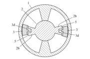
- FIG. 2 is a cross-sectional view of the rotary damper according to the embodiment, showing a state in which the oil passage formed between the valve and the rotor is closed.
- FIG. 3 is a cross-sectional view of the rotary damper according to the embodiment, showing a state in which the oil passage formed between the valve and the rotor is open.
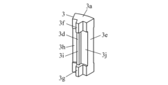
- FIG. 4 is a front perspective view of the valve employed in the example.
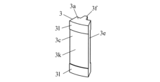
- FIG. 5 is a rear perspective view of the valve employed in the example.
- FIG. 6 is a plan view of the valve employed in the example.
- FIG. 7 is a front view of the valve employed in the example.
- FIG. 8 is a rear view of the valve employed in the example.
- FIG. 1 is a longitudinal sectional view of a rotary damper according to an embodiment.
- FIG. 2 is a cross-sectional view of the rotary damper according to the embodiment, showing
- FIG. 9 is a right side view of the valve employed in the example.
- FIG. 10 is a cross-sectional view of the valve employed in the example.
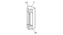
- FIG. 11 is a front perspective view of a valve employed in a comparative example.
- FIG. 12 is a rear perspective view of the valve employed in the comparative example.
- Figure 13 shows the number of operations in the comparative example, the distance between the first end surface of the valve adopted in the comparative example and the first surface of the oil chamber, and the distance between the second end surface of the valve adopted in the comparative example and the second surface of the oil chamber. It is a graph showing the relationship between the flow rate of oil passing between.
- FIG. 10 is a cross-sectional view of the valve employed in the example.
- FIG. 11 is a front perspective view of a valve employed in a comparative example.
- FIG. 12 is a rear perspective view of the valve employed in the comparative example.
- Figure 13 shows the number of operations in the comparative example, the distance between the first end surface of the
- FIG. 14 is a graph showing the relationship between the number of operations in the comparative example and the flow rate of oil passing between the back surface of the valve and the curved surface of the oil chamber employed in the comparative example.
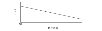
- FIG. 15 is a graph showing the relationship between the number of operations and torque in a comparative example.
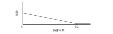
- FIG. 16 shows the number of operations in the example, the distance between the first end surface of the valve adopted in the example and the first surface of the oil chamber, and the distance between the second end surface of the valve adopted in the example and the second surface of the oil chamber. It is a graph showing the relationship between the flow rate of oil passing between.
- FIG. 15 is a graph showing the relationship between the number of operations and torque in a comparative example.
- FIG. 16 shows the number of operations in the example, the distance between the first end surface of the valve adopted in the example and the first surface of the oil chamber, and the distance between the second end surface of the valve adopted in the example and the second surface of the oil chamber. It is a graph showing the relationship between the flow rate of
- FIG. 17 is a graph showing the relationship between the number of operations in the example and the flow rate of oil passing between the back surface of the valve employed in the example and the curved surface of the oil chamber.
- FIG. 18 is a graph showing the relationship between the number of operations and torque in the example.
- the rotary damper As shown in FIG. 1, the rotary damper according to the embodiment includes a housing (1), a rotor (2), and a valve (3).
- the housing (1) includes a cylindrical peripheral wall (1a), a lid (1b) that closes one end of the peripheral wall (1a), and an end that closes the other end of the peripheral wall (1a). It includes a wall (1c), a partition wall (1d) protruding from the inner circumferential surface of the circumferential wall (1a), and a flange (1e) protruding from the outer circumferential surface of the circumferential wall (1a).
- the partition wall (1d) is a partition that separates two oil chambers (4) formed inside the housing (1). Oil is injected into each oil chamber (4).
- the flange (1e) is connected to an object that prevents rotation of the housing (1) or that transmits rotational force to the housing (1).
- the rotor (2) includes a shaft (2a) and a protrusion (2b) protruding from the outer peripheral surface of the shaft (2a).
- the shaft portion (2a) is connected to an object that transmits rotational force to the rotor (2) or an object that prevents rotation of the rotor (2).
- a protrusion (2b) is arranged in each oil chamber (4).
- the protrusion (2b) has a longitudinal groove (2c) at its tip.
- the valve (3) is installed between the peripheral wall (1a) of the housing (1) and the protrusion (2b) of the rotor (2). As shown in FIGS. 4 to 10, the valve (3) has a first end surface (3a), a second end surface (3b), a back surface (3c), and a valve portion (3d).
- the first end surface (3a) of the valve (3) is a first surface (4a) that closes one end of the oil chamber (4) (i.e., the lid (1b) in the embodiment).
- the second end surface (3b) of the valve (3) is opposite to the bottom surface (bottom surface), and the second end surface (3b) of the valve (3) is opposite to the second surface (4b) (i.e., in the embodiment, the end wall (1c)
- the back surface (3c) of the valve (3) faces the curved surface (4c) of the oil chamber (4) (that is, the inner peripheral surface of the peripheral wall (1a) in the embodiment).
- the first protrusion (3f) and the second protrusion (3g) are arranged in the longitudinal groove (2c) formed in the rotor (2), and the longitudinal groove ( 2c) is movable in the circumferential direction.
- the valve part (3d) of the valve (3) is formed between the first protrusion (3f) and the second protrusion (3g). .
- the valve (3) has a first groove (3h) extending from the left side of the main body (3e) to the left side of the valve part (3d).
- a second groove (3i) extending from the left side of the first protrusion (3f) and the second protrusion (3g) to the right side of the first protrusion (3f) and the second protrusion (3g), and a valve.
- It has a third groove (3j) extending from the right side surface of the portion (3d) to the right side surface of the main body portion (3e).
- the rotary damper according to the embodiment has an oil passage (5) formed between the valve (3) and the rotor (2).
- This oil passage (5) has a gap between the first groove (3h) of the valve (3) and the tip of the protrusion (2b) of the rotor (2), and a gap between the second groove (3i) of the valve (3) and the rotor. (2), and a gap between the third groove (3j) of the valve (3) and the tip of the protrusion (2b) of the rotor (2).
- the valve (3) employed in the example has a valve part (3d) that closes the oil passage (5) formed between the rotor (2) and the valve part (3d). ) closes the oil passage (5) to prevent the oil injected into the oil chamber (4) from flowing back through the oil passage (5).
- the valve portion (3d) of the valve (3) Since the oil leaves the protrusion (2b) of the rotor (2), the oil flows through the oil passage (5).
- the rotary damper according to the embodiment generates effective torque when the oil passage (5) is closed by the valve (3).
- the rotor (2) or the housing (1) rotates, between the first end surface (3a) of the valve (3) and the first surface (4a) of the oil chamber (4), ) and the curved surface (4c) of the oil chamber (4), or friction occurs between the second end surface (3b) of the valve (3) and the second surface of the oil chamber (4). (4b) and between the back surface (3c) of the valve (3) and the curved surface (4c) of the oil chamber (4). Therefore, the valve (3) wears out due to repeated rotations of the rotor (2) or the housing (1).
- the bulb (3) employed in the example has unevenness (3k, 3l) on the back surface (3c).
- a gap (6) is formed between the recess (3k) of the unevenness (3k, 3l) and the curved surface (4c) of the oil chamber (4). Since oil can pass through this gap (6) when the valve part (3d) of the valve (3) closes the oil passage (5), this gap (6) reduces the torque.
- the oil employed in the example has sufficient viscosity to prevent the torque from decreasing due to the gap (6). That is, the viscosity of the oil employed in the example is set higher than the viscosity of the oil used in the comparative example so that it can generate torque equivalent to that of the comparative example described later.
- the cross-sectional area of the gap (6) formed by the recess (3k) between the valve (3) and the peripheral wall (1a) of the housing (1) is reduced by the wear of the protrusion (3l) of the unevenness (3k, 3l). to shrink.
- the decrease in torque due to wear of the first end surface (3a) and/or the second end surface (3b) is compensated for by the increase in torque due to the reduction in the cross-sectional area of the gap (6). Therefore, reduction in torque due to wear of the valve (3) can be reduced.
- the function of the valve part (3d) of the valve (3) is not impaired by wear of the convex part (3l).
- the "function" of the valve part (3d) means the ability of the valve part (3d) to close the oil passage (5).
- the cross-sectional area of the oil passage (5) (specifically, the cross-sectional area of the gap between the first groove (3h) of the valve (3) and the tip of the protrusion (2b) of the rotor (2)) is , enlarges due to wear of the convex portion (3l).
- the left side surface of the valve part (3d) of the valve (3) adopted in the example has a sufficient area to completely close the oil passage (5) even after the cross-sectional area of the oil passage (5) is expanded. has.
- valve portion (3d) is not impaired by wear of the convex portion (3l). According to the valve (3) having this valve portion (3d), it is possible to prevent oil from flowing backward through the oil passage (5) and to enhance the compensation effect by reducing the cross-sectional area of the gap (6). can.
- the embodiment provides a method for preventing a decrease in torque of a rotary damper due to wear of the valve (3).
- This method is based on the expansion of the gap between the second end surface (3b) of the valve (3) and the second surface (4b) of the oil chamber (4) due to wear of the first end surface (3a) of the valve (3), or (3)
- the reduction in torque due to the enlargement of the gap between the first end surface (3a) of the valve (3) and the first surface (4a) of the oil chamber (4) due to wear of the second end surface (3b) of the valve (3) This is prevented by reducing the cross-sectional area of the gap (6) due to wear of the convex portion (3l).
- the bulb (3') adopted in the comparative example differs from the bulb (3) adopted in the example in that no unevenness is formed on its back surface (3c').
- the other configurations of the comparative example are the same as those of the example.
- the "flow rate” is the estimated amount of oil that passes through a specific location within a unit time
- the “number of operations” is the amount of oil that flows through the rotor (2) in one direction (oil path (5)).
- “N1” is the number of times the valve (3, 3') is rotated when wear occurs in the valve (3, 3').
- “torque” is the torque generated when the rotor (2) is rotated in one direction (the direction in which the oil passage (5) is closed).
- “N2" is the number of operations when the convex portion (3l) is completely worn out.
Landscapes
- Engineering & Computer Science (AREA)
- General Engineering & Computer Science (AREA)
- Mechanical Engineering (AREA)
- Fluid-Damping Devices (AREA)
Abstract
Description
1.油室の一端を閉塞する第1の面に対向する第1端面、前記油室の他端を閉塞する第2の面に対向する第2端面、前記油室の湾曲面に対向する背面、及びローターとの間に形成される油路を閉じる弁部を有し、前記弁部が前記油路を閉じることによって前記油室に注入されるオイルが前記油路を通って逆流することを防止するバルブを備え、
前記バルブは前記背面に凹凸を有し、
前記凹凸の凹部は前記湾曲面との間に隙間を形成し、
前記隙間の断面積は前記凹凸の凸部の摩耗によって縮小し、
前記弁部の機能は前記凸部の摩耗によって損なわれない
ことを特徴とするロータリーダンパ。
2.油室の一端を閉塞する第1の面に対向する第1端面、前記油室の他端を閉塞する第2の面に対向する第2端面、前記油室の湾曲面に対向する背面、及びローターとの間に形成される油路を閉じる弁部を有し、前記弁部が前記油路を閉じることによって前記油室に注入されるオイルが前記油路を通って逆流することを防止するバルブを備え、
前記バルブは前記背面に凹凸を有し、
前記凹凸の凹部は前記湾曲面との間に隙間を形成し、
前記オイルが前記隙間によるトルクの低下を防止するのに十分な粘度を有し、
前記隙間の断面積は前記凹凸の凸部の摩耗によって縮小し、
前記弁部の機能は前記凸部の摩耗によって損なわれない
ことを特徴とするロータリーダンパ。
3.ロータリーダンパ用のバルブであって、
前記バルブは油室の一端を閉塞する第1の面に対向する第1端面、前記油室の他端を閉塞する第2の面に対向する第2端面、前記油室の湾曲面に対向する背面、ローターとの間に形成される油路を閉じる弁部、及び前記背面に形成される凹凸を有し、前記弁部が前記油路を閉じることによって前記油室に注入されるオイルが前記油路を通って逆流することを防止し、
前記凹凸の凹部は前記湾曲面との間に隙間を形成し、
前記隙間の断面積は前記凹凸の凸部の摩耗によって縮小し、
前記弁部の機能は前記凸部の摩耗によって損なわれない
ことを特徴とするバルブ。
4.バルブの摩耗によるロータリーダンパのトルクの低下を防止する方法であって、
前記バルブとして、油室の一端を閉塞する第1の面に対向する第1端面、前記油室の他端を閉塞する第2の面に対向する第2端面、前記油室の湾曲面に対向する背面、ローターとの間に形成される油路を閉じる弁部、及び前記背面に形成される凹凸を有し、前記弁部が前記油路を閉じることによって前記油室に注入されるオイルが前記油路を通って逆流することを防止し、前記凹凸の凹部は前記湾曲面との間に隙間を形成し、前記隙間の断面積は前記凹凸の凸部の摩耗によって縮小し、前記弁部の機能は前記凸部の摩耗によって損なわれないものを使用し、
前記第1端面の摩耗による前記第2端面と前記第2の面との間隙の拡大又は前記第2端面の摩耗による前記第1端面と前記第1の面との間隙の拡大によるトルクの低下を、前記凸部の摩耗による前記隙間の断面積の縮小によって防ぐことを特徴とする方法。
5.バルブの摩耗によるロータリーダンパのトルクの低下を防止する方法であって、
前記バルブとして、油室の一端を閉塞する第1の面に対向する第1端面、前記油室の他端を閉塞する第2の面に対向する第2端面、前記油室の湾曲面に対向する背面、ローターとの間に形成される油路を閉じる弁部、及び前記背面に形成される凹凸を有し、前記弁部が前記油路を閉じることによって前記油室に注入されるオイルが前記油路を通って逆流することを防止し、前記凹凸の凹部は前記湾曲面との間に隙間を形成し、前記隙間の断面積は前記凹凸の凸部の摩耗によって縮小し、前記弁部の機能は前記凸部の摩耗によって損なわれないものを使用し、
前記オイルが前記隙間によるトルクの低下を防止するのに十分な粘度を有し、
前記第1端面の摩耗による前記第2端面と前記第2の面との間隙の拡大又は前記第2端面の摩耗による前記第1端面と前記第1の面との間隙の拡大によるトルクの低下を、前記凸部の摩耗による前記隙間の断面積の縮小によって防ぐことを特徴とする方法。
本発明のバルブによれば、油室の湾曲面に対向する背面に凹凸が形成され、前記凹凸の凹部が前記湾曲面との間に隙間を形成し、前記隙間の断面積が前記凹凸の凸部の摩耗によって縮小し、弁部の機能が前記凸部の摩耗によって損なわれないため、前記バルブの摩耗によるロータリーダンパのトルクの低下を防止することが可能である。
本発明の方法によれば、バルブとして、油室の一端を閉塞する第1の面に対向する第1端面、前記油室の他端を閉塞する第2の面に対向する第2端面、前記油室の湾曲面に対向する背面、ローターとの間に形成される油路を閉じる弁部、及び前記背面に形成される凹凸を有し、前記弁部が前記油路を閉じることによって前記油室に注入されるオイルが前記油路を通って逆流することを防止し、前記凹凸の凹部は前記湾曲面との間に隙間を形成し、前記隙間の断面積は前記凹凸の凸部の摩耗によって縮小し、前記弁部の機能は前記凸部の摩耗によって損なわれないものを使用し、前記第1端面の摩耗による前記第2端面と前記第2の面との間隙の拡大又は前記第2端面の摩耗による前記第1端面と前記第1の面との間隙の拡大によるトルクの低下を、前記凸部の摩耗による前記隙間の断面積の縮小によって防ぐため、前記バルブの摩耗によるロータリーダンパのトルクの低下を防止することが可能である。
1a 周壁
1b 蓋
1c 端壁
1d 隔壁
1e フランジ
2 ローター
2a 軸部
2b 突起
2c 縦溝
3 バルブ
3a 第1端面
3b 第2端面
3c 背面
3d 弁部
3e 本体部
3f 第1突出部
3g 第2突出部
3h 第1の溝
3i 第2の溝
3j 第3の溝
3k 凹部
3l 凸部
4 油室
4a 第1の面
4b 第2の面
4c 湾曲面
5 油路
6 隙間
Claims (5)
- 油室の一端を閉塞する第1の面に対向する第1端面、前記油室の他端を閉塞する第2の面に対向する第2端面、前記油室の湾曲面に対向する背面、及びローターとの間に形成される油路を閉じる弁部を有し、前記弁部が前記油路を閉じることによって前記油室に注入されるオイルが前記油路を通って逆流することを防止するバルブを備え、
前記バルブは前記背面に凹凸を有し、
前記凹凸の凹部は前記湾曲面との間に隙間を形成し、
前記隙間の断面積は前記凹凸の凸部の摩耗によって縮小し、
前記弁部の機能は前記凸部の摩耗によって損なわれない
ことを特徴とするロータリーダンパ。 - 前記オイルが前記隙間によるトルクの低下を防止するのに十分な粘度を有することを特徴とする請求項1に記載のロータリーダンパ。
- ロータリーダンパ用のバルブであって、
前記バルブは油室の一端を閉塞する第1の面に対向する第1端面、前記油室の他端を閉塞する第2の面に対向する第2端面、前記油室の湾曲面に対向する背面、ローターとの間に形成される油路を閉じる弁部、及び前記背面に形成される凹凸を有し、前記弁部が前記油路を閉じることによって前記油室に注入されるオイルが前記油路を通って逆流することを防止し、
前記凹凸の凹部は前記湾曲面との間に隙間を形成し、
前記隙間の断面積は前記凹凸の凸部の摩耗によって縮小し、
前記弁部の機能は前記凸部の摩耗によって損なわれない
ことを特徴とするバルブ。 - バルブの摩耗によるロータリーダンパのトルクの低下を防止する方法であって、
前記バルブとして、油室の一端を閉塞する第1の面に対向する第1端面、前記油室の他端を閉塞する第2の面に対向する第2端面、前記油室の湾曲面に対向する背面、ローターとの間に形成される油路を閉じる弁部、及び前記背面に形成される凹凸を有し、前記弁部が前記油路を閉じることによって前記油室に注入されるオイルが前記油路を通って逆流することを防止し、前記凹凸の凹部は前記湾曲面との間に隙間を形成し、前記隙間の断面積は前記凹凸の凸部の摩耗によって縮小し、前記弁部の機能は前記凸部の摩耗によって損なわれないものを使用し、
前記第1端面の摩耗による前記第2端面と前記第2の面との間隙の拡大又は前記第2端面の摩耗による前記第1端面と前記第1の面との間隙の拡大によるトルクの低下を、前記凸部の摩耗による前記隙間の断面積の縮小によって防ぐことを特徴とする方法。 - 前記オイルが前記隙間によるトルクの低下を防止するのに十分な粘度を有することを特徴とする請求項4に記載の方法。
Priority Applications (3)
| Application Number | Priority Date | Filing Date | Title |
|---|---|---|---|
| EP23788229.5A EP4509024A4 (en) | 2022-04-13 | 2023-04-05 | ROTARY DAMPER AND VALVE, AND METHOD FOR PREVENTING THE REDUCTION OF TORQUE IN A ROTARY DAMPER CAUSED BY VALVE WEAR |
| CN202380033273.3A CN119032229A (zh) | 2022-04-13 | 2023-04-05 | 旋转阻尼器、阀以及防止因阀的磨损导致的旋转阻尼器的转矩的降低的方法 |
| US18/856,379 US20250257779A1 (en) | 2022-04-13 | 2023-04-05 | Rotary Damper and Valve, and Method for Preventing Reduction in Torque of Rotary Damper Caused by Wear of Valve |
Applications Claiming Priority (2)
| Application Number | Priority Date | Filing Date | Title |
|---|---|---|---|
| JP2022-066595 | 2022-04-13 | ||
| JP2022066595A JP7716104B2 (ja) | 2022-04-13 | 2022-04-13 | ロータリーダンパ及びバルブ並びにバルブの摩耗によるロータリーダンパのトルクの低下を防止する方法 |
Publications (1)
| Publication Number | Publication Date |
|---|---|
| WO2023199810A1 true WO2023199810A1 (ja) | 2023-10-19 |
Family
ID=88329658
Family Applications (1)
| Application Number | Title | Priority Date | Filing Date |
|---|---|---|---|
| PCT/JP2023/014052 Ceased WO2023199810A1 (ja) | 2022-04-13 | 2023-04-05 | ロータリーダンパ及びバルブ並びにバルブの摩耗によるロータリーダンパのトルクの低下を防止する方法 |
Country Status (5)
| Country | Link |
|---|---|
| US (1) | US20250257779A1 (ja) |
| EP (1) | EP4509024A4 (ja) |
| JP (1) | JP7716104B2 (ja) |
| CN (1) | CN119032229A (ja) |
| WO (1) | WO2023199810A1 (ja) |
Citations (3)
| Publication number | Priority date | Publication date | Assignee | Title |
|---|---|---|---|---|
| JPH07301272A (ja) * | 1994-04-28 | 1995-11-14 | Hitachi Powdered Metals Co Ltd | 流体圧ダンパ |
| WO2012141242A1 (ja) | 2011-04-12 | 2012-10-18 | 株式会社ソミック石川 | ロータリーダンパ |
| JP2014224582A (ja) * | 2013-05-17 | 2014-12-04 | 不二ラテックス株式会社 | 揺動ダンパー装置 |
Family Cites Families (2)
| Publication number | Priority date | Publication date | Assignee | Title |
|---|---|---|---|---|
| CN1240952C (zh) * | 2002-01-23 | 2006-02-08 | 株式会社三协精机制作所 | 使用粘性流体的阻尼器装置及其制造方法 |
| EP3301320B1 (en) * | 2016-09-30 | 2020-04-29 | Matel Hammadde Sanayi Ve Ticaret Anonim Sirketi | A rotary damper |
-
2022
- 2022-04-13 JP JP2022066595A patent/JP7716104B2/ja active Active
-
2023
- 2023-04-05 WO PCT/JP2023/014052 patent/WO2023199810A1/ja not_active Ceased
- 2023-04-05 CN CN202380033273.3A patent/CN119032229A/zh active Pending
- 2023-04-05 EP EP23788229.5A patent/EP4509024A4/en active Pending
- 2023-04-05 US US18/856,379 patent/US20250257779A1/en active Pending
Patent Citations (3)
| Publication number | Priority date | Publication date | Assignee | Title |
|---|---|---|---|---|
| JPH07301272A (ja) * | 1994-04-28 | 1995-11-14 | Hitachi Powdered Metals Co Ltd | 流体圧ダンパ |
| WO2012141242A1 (ja) | 2011-04-12 | 2012-10-18 | 株式会社ソミック石川 | ロータリーダンパ |
| JP2014224582A (ja) * | 2013-05-17 | 2014-12-04 | 不二ラテックス株式会社 | 揺動ダンパー装置 |
Non-Patent Citations (1)
| Title |
|---|
| See also references of EP4509024A4 |
Also Published As
| Publication number | Publication date |
|---|---|
| EP4509024A1 (en) | 2025-02-19 |
| JP2023156933A (ja) | 2023-10-25 |
| EP4509024A4 (en) | 2026-04-22 |
| US20250257779A1 (en) | 2025-08-14 |
| JP7716104B2 (ja) | 2025-07-31 |
| CN119032229A (zh) | 2024-11-26 |
Similar Documents
| Publication | Publication Date | Title |
|---|---|---|
| US6840355B2 (en) | Rotary damper device | |
| US20020007993A1 (en) | Rotary damper | |
| JP6480155B2 (ja) | ロータリダンパ | |
| WO2018207511A1 (ja) | 簡易自立機構を備える回転ダンパ | |
| WO2017204000A1 (ja) | ロータリダンパ | |
| WO2012141242A1 (ja) | ロータリーダンパ | |
| KR101138546B1 (ko) | 댐퍼 | |
| JP2023156933A (ja) | ロータリーダンパ及びバルブ並びにバルブの摩耗によるロータリーダンパのトルクの低下を防止する方法 | |
| JP5812784B2 (ja) | 有限角ロータリーダンパー | |
| EP1004791A1 (en) | Rotary damper | |
| JP5189208B2 (ja) | 回転ダンパ | |
| JP5341260B2 (ja) | 回転ダンパ | |
| JP3342228B2 (ja) | 回転ダンパー | |
| JP2005188636A (ja) | ロータリーダンパ | |
| JP7523182B2 (ja) | ロータリーダンパ及びその製造方法 | |
| JP4714083B2 (ja) | 回転ダンパの弁機構 | |
| JP7688945B2 (ja) | ロータリーダンパ | |
| CN102549295B (zh) | 旋转阻尼器 | |
| KR200379321Y1 (ko) | 배기구의 전동 댐퍼 구조 | |
| JP5918222B2 (ja) | ロータリーダンパ | |
| JP6877240B2 (ja) | 逆止め弁 | |
| JP7692227B2 (ja) | ロータリーダンパ | |
| JP2894583B2 (ja) | 可動弁の保護機構を備える高トルク用ダンパ | |
| JP7391823B2 (ja) | ロータリダンパ | |
| JPH0849778A (ja) | 逆止弁 |
Legal Events
| Date | Code | Title | Description |
|---|---|---|---|
| 121 | Ep: the epo has been informed by wipo that ep was designated in this application |
Ref document number: 23788229 Country of ref document: EP Kind code of ref document: A1 |
|
| WWE | Wipo information: entry into national phase |
Ref document number: 202380033273.3 Country of ref document: CN Ref document number: 2401006751 Country of ref document: TH |
|
| WWE | Wipo information: entry into national phase |
Ref document number: 18856379 Country of ref document: US |
|
| WWE | Wipo information: entry into national phase |
Ref document number: 2023788229 Country of ref document: EP |
|
| NENP | Non-entry into the national phase |
Ref country code: DE |
|
| ENP | Entry into the national phase |
Ref document number: 2023788229 Country of ref document: EP Effective date: 20241113 |
|
| WWP | Wipo information: published in national office |
Ref document number: 18856379 Country of ref document: US |