WO2023199821A1 - 建物のプレキャスト部材の再利用方法、建物の再利用方法及び、建物のプレキャスト部材の再利用評価システム - Google Patents
建物のプレキャスト部材の再利用方法、建物の再利用方法及び、建物のプレキャスト部材の再利用評価システム Download PDFInfo
- Publication number
- WO2023199821A1 WO2023199821A1 PCT/JP2023/014076 JP2023014076W WO2023199821A1 WO 2023199821 A1 WO2023199821 A1 WO 2023199821A1 JP 2023014076 W JP2023014076 W JP 2023014076W WO 2023199821 A1 WO2023199821 A1 WO 2023199821A1
- Authority
- WO
- WIPO (PCT)
- Prior art keywords
- precast
- building
- members
- reusing
- sensor
- Prior art date
- Legal status (The legal status is an assumption and is not a legal conclusion. Google has not performed a legal analysis and makes no representation as to the accuracy of the status listed.)
- Ceased
Links
Images





Classifications
-
- G—PHYSICS
- G01—MEASURING; TESTING
- G01M—TESTING STATIC OR DYNAMIC BALANCE OF MACHINES OR STRUCTURES; TESTING OF STRUCTURES OR APPARATUS, NOT OTHERWISE PROVIDED FOR
- G01M5/00—Investigating the elasticity of structures, e.g. deflection of bridges or air-craft wings
- G01M5/0033—Investigating the elasticity of structures, e.g. deflection of bridges or air-craft wings by determining damage, crack or wear
-
- E—FIXED CONSTRUCTIONS
- E04—BUILDING
- E04B—GENERAL BUILDING CONSTRUCTIONS; WALLS, e.g. PARTITIONS; ROOFS; FLOORS; CEILINGS; INSULATION OR OTHER PROTECTION OF BUILDINGS
- E04B1/00—Constructions in general; Structures which are not restricted either to walls, e.g. partitions, or floors or ceilings or roofs
- E04B1/18—Structures comprising elongated load-supporting parts, e.g. columns, girders, skeletons
- E04B1/20—Structures comprising elongated load-supporting parts, e.g. columns, girders, skeletons the supporting parts consisting of concrete, e.g. reinforced concrete, or other stonelike material
- E04B1/21—Connections specially adapted therefor
- E04B1/215—Connections specially adapted therefor comprising metallic plates or parts
Definitions
- the present invention relates to a method for reusing precast members that constitute the frame of a building with a rigid-frame structure and include precast concrete, a precast member that constitutes the frame of a rigid-frame structure and includes precast concrete, and a plurality of interior units arranged in the frame. and a reuse evaluation system for precast members of rigid-frame structures.
- precast concrete pillar members and beam members have been used for the pillars and beams of buildings with rigid frame structures. These precast members are often rigidly connected to each other using mechanical reinforcing joints and grout.
- Precast members are manufactured in factories under predetermined quality control, undergo product inspections and shipping inspections, and only those that pass these inspections are shipped and used in building construction. During the construction of a building, precast members are handled under specific construction controls. Even when a building is demolished, precast members are handled under specified construction management.
- precast members may be damaged while being used in buildings, and the above-mentioned conventional technology does not guarantee the quality of precast members for reuse when such damage occurs. I wouldn't.
- an aspect of the present invention provides precast members (11, 12, 13, 111, 113), when constructing the building comprising a plurality of the precast members including a plurality of column members (13, 113) and a plurality of beam members (11, 12, 111), A step of attaching a sensor (55) for detecting a predetermined physical quantity (P) to at least one of the precast members that is joined to the other precast member by an unbonded tendon (26, 36, 46).
- the method includes a step of determining reusability of a member (ST14, ST22), and a step of reusing the precast member determined to be reusable for another building to be constructed (ST16, ST26).
- the quality of the precast members used in the building can be guaranteed by determining the reusability of the precast members. This makes it possible to construct safe buildings by reusing precast members.
- the sensor in the step of attaching the sensor (ST5), when constructing the building in which the beam member is joined to the column member by the unbonded tendon, the sensor is attached to the beam member, and the precast In the step (ST14) of determining the reusability of the beam member, it is preferable to determine the reusability of the beam member when demolishing the building.
- the quality of the beam members can be guaranteed by determining the reusability of the beam members that are easily damaged by earthquakes.
- the column member (113) has a hollow structure, and when constructing the building, the hollow part (114) of the column member is filled with cast-in-place concrete after the column member is erected at a predetermined position. (116) is preferably installed.
- the pillar member is lighter than when it has a solid structure. Therefore, the transportation efficiency of the column member is improved and it can be lifted with a small crane, which is advantageous for construction in urban areas.
- the method for reusing a precast member further includes a step (ST14, ST24) of visually inspecting whether or not there is an abnormality in appearance of the beam member determined to be reusable; It is best to determine that the item can be reused only if the above abnormalities are not present.
- the method for reusing precast members includes performing a predetermined inspection on the precast member after demolishing the building (ST13, ST28), and based on the detection result of the sensor and the result of the predetermined inspection, It is preferable to further include a step of determining the degree of damage to the precast member (ST14, ST29), and a step of repairing the precast member to a reusable state according to the degree of damage (ST18, ST31).
- the precast member can be repaired to a reusable state by performing a predetermined inspection after the building is demolished.
- the quality of the precast members can be reliably guaranteed, and the number of reusable precast members can be increased. Therefore, it is possible to reduce the amount of CO 2 emitted during the production of precast members.
- another aspect of the present invention includes precast members (11, 12, 13, 111, 113) that constitute a rigid frame structure (2 (2X, 2Y), 102) and that include precast concrete. and a method for reusing a building (1) including a plurality of interior units (50) disposed within the frame, comprising a plurality of column members (13, 113) and a plurality of beam members (11, 12, 111). in constructing the frame comprising a plurality of the precast members including at least one of the precast members joined to other precast members by unbonded tendons (26, 36, 46).
- the method includes steps of reusing the interior unit in another building (ST16, ST26), and reusing the interior unit in another building (ST16, ST26).
- the quality of the precast members can be guaranteed more reliably, the reliability of the building frame using the precast members can be improved, and the quality of the interior units placed in the frame can be guaranteed.
- the building reuse method may further include a step (ST7) of providing a predetermined section of the building for limited use.
- a predetermined section has a time limit, it is possible to respond to the replacement or change of use of components in the section based on a plan, and the quality assurance of precast components is further ensured. At the same time, the reliability of the building frame using the precast member can be improved.
- another aspect of the present invention is to provide precast members (11, 12, 13) that constitute the frame (2 (2 , 111, 113), which includes a plurality of column members (13, 113) and a plurality of beam members (11, 12, 111).
- the quality of the precast members used in the building can be guaranteed by determining the reusability of the precast members. This makes it possible to construct safe buildings by reusing precast members.
- the monitoring device determines whether the physical quantity detected by the sensor is within a predetermined first reference value (Pth1), and if the physical quantity is within the first reference value; It is preferable to determine that it can be reused (ST14, ST22).
- the monitoring device requires replacement of the member when the physical quantity of the precast member exceeds a second reference value (Pth2) that is larger than the first reference value while the building is in use. It is preferable to determine this (ST8).
- the precast member is no longer suitable for use. This can improve the safety of buildings in which precast members are used.
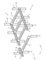
- a perspective view showing a partially exploded structure of a building according to the first embodiment (A) Side view (II arrow view in Figure 1) showing the connection structure of the first beam, (B) Cross-sectional view (BB cross section in A) (A) Side view and (B) cross-sectional view of section III in Figure 2 (BB cross-section in A) (A) Side view (IV arrow view in Figure 1) and (B) sectional view (BB cross section in A) showing the connection structure of the second beam Side view showing the column connection structure (view from arrow IV in Figure 1)
- Configuration diagram of reuse evaluation system Flow diagram for construction and use of precast parts and building reuse methods Flow diagram during demolition of precast parts and building reuse method Flow diagram at the time of dismantling the precast member and building reuse method according to the second embodiment
- inside and outside mean the inside and outside of the building.
- the frame 2 of the building 1 (see FIG. 6) consists of a plurality of reinforced concrete structures arranged at predetermined intervals in the X and Y directions intersecting on a horizontal plane.
- the pillars 3 are arranged in three or more rows in the X direction and in two rows in the Y direction. Therefore, all four pillars 3 arranged at the ends in the X direction are corner pillars.
- Reinforced concrete here refers to reinforcing bars, reinforcing fibers (carbon fiber, glass fiber, aramid fiber, etc.), and PC materials (slender members used to introduce prestress into concrete) to increase the strength of concrete (especially tensile strength). It means a concrete-based material in which reinforcing materials (PC steel wire, PC steel rod, PC steel stranded wire, FRP rod, other wire or rod-shaped members) are embedded or mixed.
- Reinforced concrete may be reinforced concrete (RC), FRC (Fiber Reinforced Concrete), PRC (Prestressed Reinforced Concrete), PC (Prestressed Concrete), or other types as long as the main material is concrete-based material. It's okay.
- a plurality of first beams 4 made of reinforced concrete extending in the X direction are installed between the columns 3 and 3 adjacent to each other in the X direction.
- An X-direction frame 2X is constructed that extends to.
- a plurality of second beams 5 made of reinforced concrete extending in the Y direction are installed between the columns 3 and 3 adjacent to each other in the Y direction, and these columns 3 and 3 and the second beams 5
- a Y-direction frame 2Y extending in the Y-direction is constructed.
- the first beam 4 and the second beam 5 are joined to the column 3 at positions where they overlap each other in the vertical direction.
- the joint between the column 3 and the first beam 4 and the joint between the column 3 and the second beam 5 constitute a common joint in the column 3 (in the vertical direction).
- a slab (not shown) is constructed above or above these first beams 4 and second beams 5.
- the second beam 5 is longer than the first beam 4, and the pitch of the columns 3 in the Y direction is larger than the pitch of the columns 3 in the X direction.
- One or more small beams extending in the X direction may be constructed between the two second beams 5, 5 that are adjacent to each other in the X direction.
- the first beam 4, the second beam 5, and the slab are constructed in multiple layers at different positions in the vertical direction. That is, the frame 2 has a multilayer rigid frame structure.
- This frame 2 has the configuration described below, so it is easy to assemble and disassemble, and it can be reused. Therefore, this frame 2 is suitable for a limited-term building (a building that is intermediate between a temporary building and a permanent building, such as an expo facility or temporary housing for disaster victims).
- the frame 2 is also suitable for use in expanding or reducing the size of a building, or increasing or decreasing the height of a building.
- the frame 2 may be used in buildings such as distribution warehouses, office buildings, housing complexes, and commercial facilities.
- the frame 2 is constructed by assembling multiple types of precast concrete members (hereinafter referred to as precast members). These precast members include a plurality of first beam members 11, a plurality of second beam members 12, and a plurality of column members 13 for each level.
- the first beam member 11 is joined to the upper surface of the column member 13 and is integrally formed with the joint part 21 that forms the joint of the pillar 3, and extends from the joint part 21 in at least one of the X directions. It has at least one first beam main body part 22 that extends out and forms a part of the first beam 4.
- the column member 13 forms the main body of the column 3 (in the illustrated example, the entire portion below the joint), and is joined to the upper surface of the joint part 21 of the first beam member 11 on the foundation or the lower layer. .
- the column members 13 are divided into upper and lower parts and two or more precast members are used to cover one layer.
- the portion of the pillar 3 other than the joint portion 21 may be configured.
- the column member 13 is a precast member made of RC structure to which no prestress is introduced.
- the joint part 21 of the lower layer first beam member 11 is joined to the upper surface of the lower layer column member 13, and the upper layer column member 13 is joined to the upper surface of the joint part 21 of the lower layer first beam member 11.
- the layers of the building increase. That is, the column member 13 is provided between the first beam member 11 of the layer (lower layer) and the first beam member 11 of the upper layer.
- the first beam member 11 joined to the upper surface of the column member 13 of the column 3 located at the end in the X direction has a joint part 21 and one first beam main body part 22.
- the first beam member 11 joined to the upper surface of the column member 13 of the other columns 3 has a joint portion 21 and two first beam main body portions 22 .
- these first beam members 11 have mutually different shapes, they are both referred to as first beam members 11 here.
- the first beam main body portion 22 of each first beam member 11 constitutes a beam half portion that is approximately half of the first beam 4.
- one first beam main body part 22 of the first beam member 11 may have a different length from the other first beam main body part 22.
- the two first beam members 11 forming the joints of the pillars 3 that are arranged adjacent to each other in the X direction are arranged so that the front end surfaces of the first beam main bodies 22 are adjacent to each other and face each other, and are continuous in the X direction. be done.
- the second beam member 12 constitutes the entire second beam 5 and is formed separately from the joint portion 21 of the column 3.
- the end portion of the second beam 5 may be integrally formed with the joint portion 21 of the column member 13.
- the second beam member 12 has both ends joined to the joint portions 21 of a pair of pillars 3 that are arranged adjacent to each other in the Y direction.
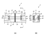
- FIG. 2 is (A) a side view (II arrow direction view in FIG. 1) and (B) a cross-sectional view (BB cross section in A) of the first beam 4.
- the first beam main body portion 22 of the first beam member 11 has a rectangular cross-sectional shape at the tip portion 23, and the other portion (hereinafter referred to as the general portion 24) has a vertically intermediate portion. It has an I-shaped cross-sectional shape with both sides concave at the portion.
- the tip end portion 23 of the first beam main body portion 22 forms a widened portion that is wider than the general portion 24 in at least a portion of the vertical direction.
- a shoulder surface facing toward the joint portion 21 is formed at the end portion of the tip portion 23 on the general portion 24 side.
- a proximal end portion having the same cross-sectional shape as the distal end portion 23 may be provided at the end portion of the general portion 24 of the first beam main body portion 22 on the side of the joint portion 21 .
- the first PC material 25 may be any member such as a PC steel wire, a PC steel bar, a PC stranded wire, or an FRP rod, and in this embodiment, it is a stranded PC steel wire.
- the first PC material 25 is placed inside the first beam member 11 using a pretension method when the first beam member 11 is manufactured in a factory, and introduces prestress in the member axis direction into the first beam member 11. That is, the first beam member 11 is made of precast PC.
- the two first beam members 11 arranged continuously in the X direction are joined to each other by a plurality of first unbonded tendons 26 .
- first beam body parts 22 of the two first beam members 11 are connected in the X direction, and the entire first beam 4 is constituted by the first beam members 11 of the two first beam members 11.
- the bonding structure using the first unbonded tendon 26 will be described in detail later.
- FIG. 3 is (A) a side view and (B) a sectional view (BB cross section in A) of part III in FIG. 2.
- a plurality of first sheaths 27 are embedded in the distal end portion 23 (specifically, the widened portion) of the first beam member 11 so as to penetrate the distal end portion 23 in the X direction.
- a cover plate 28 is provided as a cover member on the end face of the tip portion 23 of the first beam member 11.
- the cover plate 28 may be made of metal or resin, for example, and may be integrally attached to the first beam member 11 or may be provided detachably. Alternatively, a cover sheet may be provided as the cover member.
- a through hole is formed in the cover plate 28 at a position corresponding to the first sheath 27.
- the two first beam members 11 arranged continuously in the X direction are arranged so that the cover plates 28 are close to each other and face each other at positions separated from each other.
- the gap between the two first beam members 11 (between the cover plates 28) is filled with a joint material 29 made of a hardening filler such as non-shrinkage mortar or resin mortar. It is preferable that the cover plate 28 is provided with an uneven portion on the surface on the joint side in order to increase the adhesion of the joint material 29.
- a connecting sheath (not shown) is provided between each pair of first sheaths 27 so that the joint material 29 does not enter into the first sheaths 27 .
- the two first beam members 11 that are continuous in the X direction are crimped (crimped-bonded) to each other by a plurality of first unbonded tendons 26 inserted so as to penetrate these first sheaths 27.
- the first unbonded tension material 26 is connected to the first tension material 26a that is inserted through these first sheaths 27, and the first tension material 26a by taking a reaction force from the shoulder surface of the distal end portion 23 of each of the first beam members 11. and a pair of first fixing metal fittings 26b that maintain the tension of.
- male threads are formed at both ends of the first tension member 26a
- the first fixing hardware 26b includes a perforated steel plate provided on the shoulder surface of the first beam member 11 and a nut having a female thread formed therein.
- the cover plate 28 is provided on the end face of the first beam member 11 in the X direction, and the cover plate 28 of each pair of first beam members 11, 11 adjacent to each other in the X direction is provided with a hardening material.
- the joint material 29 is filled. Therefore, the first beam member 11 is prevented from being damaged by local stress generated when the joining end surfaces of the first beam member 11 are directly pressed together. Further, with this configuration, manufacturing errors of the first beam member 11 and construction errors during assembly can be absorbed by the joint material 29, and manufacturing costs and construction costs can be reduced.
- FIG. 4 shows (A) a side view (view from arrow IV in FIG. 1) and (B) a cross-sectional view (BB cross-section in A) of the second beam 5.
- the second beam member 12 has a rectangular cross-sectional shape at both ends 33 in the longitudinal direction (Y direction), and the other portions (hereinafter referred to as general portions 34) have a rectangular cross-sectional shape. It has an I-shaped cross-sectional shape with both side surfaces concave in the middle of the direction.
- the tip end portion 33 of the second beam member 12 forms a widened portion that is widened relative to the general portion 34 in at least a portion of the vertical direction. Due to this widening of the distal end portion 33, a shoulder surface facing in a direction opposite to the end surface is formed at the end portion of the distal end portion 33 on the general portion 34 side.
- a plurality of second PC materials 35 extending in the Y direction are arranged at the bottom of the second beam member 12 over the entire length of the second beam member 12.
- the second PC material 35 may be any member such as a PC steel wire, a PC steel bar, a PC stranded wire, or an FRP rod, and in this embodiment, it is a stranded PC steel wire.
- the second PC material 35 is placed inside the second beam member 12 using a pretension method when the second beam member 12 is manufactured in a factory, and introduces prestress in the member axis direction to the second beam member 12. That is, the second beam member 12 is made of precast PC.
- the second beam member 12 is joined to the joint portions 21 of the two first beam members 11 spaced apart in the Y direction by a plurality of second unbonded tendons 36 .
- the joining structure of the second beam member 12 to the joint part 21 of the first beam member 11 by the second unbonded tension material 36 is the same as the joining structure described with reference to FIG. 3, so a detailed explanation is omitted. do.
- the second unbonded tendon 36 has a second tendon 36a that is inserted through the pair of second sheaths.
- the second unbonded tension material 36 receives a reaction force from the shoulder surface of the tip portion 33 of the second beam member 12 and the outer side surface of the joint portion 21 of the first beam member 11 in the Y direction, and the second tension material 36a It has a pair of second fixing hardware 36b that maintain tension.
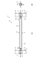
- FIG. 5 is a side view (view from arrow IV in FIG. 1) showing the connection structure of the pillar 3. Note that both the upper part and the lower part in FIG. 5 show the same part as the left part in FIG. However, since FIG. 4 is an explanatory diagram of the connection structure of the second beam member 12, it should be noted that the connection structure of the column 3 shown in FIG. 5 is omitted.
- the column member 13 includes a column main body portion 41 having a constant rectangular cross-sectional shape, inner and outer upper end protrusions 42 that protrude in the Y direction at the top of the side surface facing the Y direction, and It has inner and outer lower end protrusions 43 that protrude in the Y direction at the lower part of the side surface facing the direction.
- Each of the upper end projections 42 and each of the lower end projections 43 is a widened portion that is widened at the upper end and lower end of the pillar member 13 relative to other parts of the pillar main body portion 41 .
- Each upper end protrusion 42 forms a downwardly facing shoulder surface at its lower end
- each lower end protrusion 43 forms an upwardly facing shoulder surface at its upper end.
- the first beam member 11 has a closing protrusion 44 that projects outward in the Y direction from the closing portion 21.
- the closing projection 44 has the same height as the closing portion 21 and has a shape corresponding to the upper end projection 42 and the lower end projection 43.
- the first beam member 11 is placed on the column member 13 via a joint material 29 (see FIG. 3) so that the joint portion 21 is continuous with the column main body portion 41 of the column member 13 of the layer.
- the upper layer of the first beam member 11 is placed on the joint portion 21 of the first beam member 11 via a joint material 29 (see FIG. 3) so as to be continuous.
- the end of the second beam member 12 is placed on the inner upper end protrusion 42 of the lower column member 13 via the joint material 29, and the upper column member
- the inner lower end protrusion 43 of 13 is placed through the joint material 29.
- the joint protrusion 44 of the first beam member 11 is placed on the outer upper end protrusion 42 of the lower column member 13 via the joint material 29, and the upper column member 13 is placed on the joint protrusion 44.
- the inner lower end protrusion 43 is placed through the joint material 29.
- the joint material 29 may not be provided.
- the two pillar members 13 that are vertically adjacent to each other with the first beam member 11 in between are connected to the first beam member 13 by inner and outer third unbonded tension members 46 provided so as to vertically penetrate the upper end projection 42 and the lower end projection 43. It is joined to the joint part 21 of the beam member 11.
- the inner third unbonded tension member 46 is further provided so as to vertically penetrate the end of the second beam member 12, and its upper and lower ends are fixed to the upper end projection 42 and the lower end projection 43.
- the outer third unbonded tension material 46 is further provided so as to vertically penetrate the joint projection 44, and its upper and lower ends are fixed to the upper end projection 42 and the lower end projection 43.
- the joining structure of the two upper and lower column members 13 to the joint part 21 of the first beam member 11 by the third unbonded tension material 46 is the same as the joining structure described with reference to FIG. is omitted.
- the third unbonded tension member 46 can be removed by loosening the nut of the third fixing metal fitting 46b. In this way, each pair of column members 13, 13 adjacent to each other in the vertical direction with the joint part 21 of the first beam member 11 in between is crimped to the joint part 21 of the first beam member 11 by the third unbonded tension material 46. Therefore, grout injection work for connecting the column members 13 is also unnecessary.
- the column member 13 can be separated from the first beam member 11 after assembly by removing the third unbonded tension material 46.
- the first tension material 26a, the second tension material 36a, and the third tension material 46a may be any member such as a PC steel wire, a PC steel bar, a PC steel stranded wire, or an FRP rod. It is considered to be PC steel wire.
- the first beam member 11, the second beam member 12, and the column member 13 are assembled by crimping using the first unbonded tension member 26, the second unbonded tension member 36, and the third unbonded tension member 46, so that the frame 2 No grouting work is required during assembly.
- the frame 2 can be separated again after assembly, which eliminates the need to destroy these members (11, 12, 13) when disassembling the frame 2. There is no need to worry about this, making disassembly work easier.
- these parts (11, 12, 13) can be reused.
- the inner third unbonded tension material 46 passes through the second beam member 12 in the vertical direction, and connects the upper end protrusion 42 of the lower column member 13 and the lower end protrusion 43 of the upper column member 13 to the second beam member 12. Crimp. As a result, the two vertically adjacent column members 13, 13 are crimped to the joint part 21 of the first beam member 11 by the common inner third unbonded tension material 46 that passes through the second beam member 12, Assembly and disassembly work related to the connection of the column members 13 becomes easier.
- the outer third unbonded tension member 46 passes through the joint projection 44 in the vertical direction, and presses the upper end projection 42 of the lower column member 13 and the lower end projection 43 of the upper column member 13 to the joint projection 44. do.
- the tension force of the outer third unbonded tendon material 46 is directly transmitted from the upper end projection 42 and the lower end projection 43 to the joint projection 44 of the first beam member 11 . Therefore, compared to the case where there is a space between the upper end projection 42 and the lower end projection 43, the upper end projection 42 and the lower end projection 43 can have a simple structure with a small shear strength.
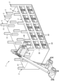
- FIG. 6 is a perspective view of a building 1 under construction, showing an example of the use of the frame 2 according to the present invention.
- the building 1 includes a frame 2 having the above configuration and a plurality of interior units 50 arranged inside the frame 2.
- a floor member 51 made of reinforced concrete is placed on the first beam 4 and second beam 5 of the frame 2, and the interior unit 50 is placed on the floor member 51.
- the floor member 51 may be placed directly on the first beam 4 and the second beam 5.
- the plurality of first beam members 11, the plurality of second beam members 12, and the plurality of column members 13 of the frame 2 are configured to be separable from each other.
- the interior unit 50 is configured to be able to be assembled to and removed from the frame 2. Specifically, the interior unit 50 is lifted by a crane without the upper first beam 4 and second beam 5 as shown in the figure, and is carried into a predetermined position within the frame 2, or It is carried out from a predetermined position.
- the interior unit 50 has a height dimension larger than the height from the upper surface of the first beam 4 and the second beam 5 adjacent to the lower side to the lower surface of the first beam 4 and the second beam 5 adjacent to the upper side. Portions corresponding to the first beam 4 and the second beam 5 that are adjacent to each other above the interior unit 50 are cut out.
- the interior unit 50 is fixed in a predetermined position by the frame 2 by constructing the first beam 4 and the second beam 5 adjacent to each other above. In other embodiments, the interior unit 50 may be fixed to the frame 2 by a fixing member.
- the interior unit 50 can be slid onto a support stand (not shown) disposed on the side of the frame 2 while the first beam 4 and the second beam 5 adjacent to the top are constructed. may be imported into Similarly, the interior unit 50 may be carried out from the inside of the frame 2 by sliding on a support stand disposed on the side. In this case, the interior unit 50 is preferably fixed to the frame 2 using a fixing member.
- the plurality of precast members are configured to be separable from each other, and the interior unit 50 is configured to be able to be assembled to and removed from the frame 2.
- FIG. 7 is a configuration diagram of the reuse evaluation system 100 according to the present invention.
- the reuse evaluation system 100 includes a plurality of sensors 55 and a monitoring device 60.
- the sensor 55 is attached to a plurality of precast members including the first beam member 11, the second beam member 12, and the column member 13 (see FIG. 1), and measures a predetermined physical quantity P.
- the predetermined physical quantity P may include, for example, at least one of acceleration and distortion, and may also include temperature, humidity, and the like.
- the monitoring device 60 includes an arithmetic processing device 61 (processor such as a CPU, MPU, etc.) and a storage device 62 (memory such as a ROM, RAM, etc.), and is configured to execute various processes necessary for determining component availability. Consists of a computer.
- the monitoring device 60 is configured to execute various processes, which means that the arithmetic processing unit 61 that constitutes the monitoring device 60 reads necessary data and application software from the storage device 62, and executes the predetermined calculation according to the software. It means that it is programmed to perform a process.
- the arithmetic processing unit 61 of the monitoring device 60 writes the detection results of the sensor 55 into the storage device 62 for storage.
- the monitoring device 60 includes a database in a storage device 62 that stores various data on each precast member (11 to 13).
- the database may include identification numbers of precast members, member types, dimensions, specifications, manufacturing plants, manufacturing dates, specification history, storage history, logs of sensor detection data during use, and the like.
- the monitoring device 60 determines whether or not the precast members (11 to 13 ) is monitored.
- the monitoring device 60 is configured to execute a determination process including determining whether or not the precast member can be continuously used and whether or not it can be reused based on the detection result of the sensor 55. The determination process will be explained later in the precast member reuse method.
- the monitoring device 60 also includes a display 63, and displays the physical quantity P being monitored and the determination results on the display 63.
- the monitoring device 60 may include a wireless or wired information transmitting device, and transmit the physical quantity P being monitored and the determination result to a terminal accessible by the administrator.
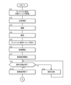
- FIGS. 8 and 9 are flowcharts of a method for reusing precast members and the building 1, with FIG. 8 showing the state during construction and use, and FIG. 9 showing the state during dismantling.
- the precast member and interior unit 50 are manufactured under predetermined quality control in a precast factory and an interior unit factory (step ST1).
- the manufactured precast members and interior units 50 undergo a shipping inspection at the factory (step ST2), and only those that pass the shipping inspection are shipped and transported to a predetermined construction site (step ST3). Thereafter, the precast member and interior unit 50 are used to construct the building 1 on site (step ST4).
- the sensor 55 When constructing the building 1, the sensor 55 is attached to the precast member by a worker (step ST5) and connected to the monitoring device 60. Alternatively, the sensor 55 may be attached to the precast member at the time of factory shipment, and only the work of connecting the sensor 55 to the monitoring device 60 may be performed on site when constructing the building 1. The sensor 55 may be attached only to a representative part that can detect a deterioration factor that is assumed in advance, depending on the deterioration factor. Thereafter, monitoring of the physical quantity P of the precast member by the monitoring device 60 is started (step ST6). Furthermore, use of the building 1 is started (step ST7). The monitoring device 60 stores the physical quantity P of the precast member in the storage device 62 and monitors the physical quantity P while the building 1 is in use. Monitoring by the monitoring device 60 is performed continuously or intermittently while the building 1 is in use.
- While the building 1 is in use, a predetermined section of the building 1 is provided for use for a limited period of time.
- the frame 2 of the building 1 is owned by a leasing company. Businesses to be leased to include real estate developers and sole proprietors. The business operator who has received the lease of the frame 2 of the building 1 may further rent each section to various businesses such as housing companies, office rental companies, hotel operators, etc., with a limited period of time.
- the leasing company may become a business entity that directly uses the building 1 to conduct business such as an office rental business or a hotel business.
- the monitoring device 60 repeatedly determines whether or not each precast member can be continuously used while the building 1 is in use. Specifically, the monitoring device 60 determines that the member needs to be replaced when the physical quantity P of the precast member exceeds a predetermined second reference value Pth2 (step ST8).
- the frequency of the availability determination may be arbitrary, for example, once every few months or after an event such as an earthquake occurs. If it is determined that the component needs to be replaced (ST8: Yes), the monitoring device 60 displays the determination result that the component needs to be replaced on the display 63. As a result, the administrator can recognize that the precast member needs to be replaced, and therefore the precast member that needs to be replaced is replaced (step ST9). After the precast member is replaced, the physical quantity P of the precast member is continuously monitored.
- step ST10 When the period of use of the building 1 has elapsed without determining that component replacement is necessary (ST8: No), the use of the building 1 ends (step ST10).
- building 1 is demolished (step ST11).
- each precast member and interior unit 50 are transported from the demolition site to an inspection site (step ST12).
- the inspection site may be any place that is equipped with equipment to perform predetermined inspections or inspections on the precast members or interior unit 50, and may be, for example, a precast factory, a prefab factory, a storage warehouse for storing them, or the like.
- a predetermined inspection of the precast member is performed by a worker and an inspection device (step ST13). Further, the interior unit 50 is inspected by a worker or an inspection device (step ST13). After the inspection, the degree of damage to the precast member is determined based on the detection result by the sensor 55 and the predetermined inspection result (step ST14). Furthermore, after the inspection, the degree of damage to the interior unit 50 is determined based on the inspection results (step ST14).
- the degree of damage to the precast member is determined by a computer by comprehensively judging the results of monitoring by the sensor 55 and the inspection results in accordance with predetermined criteria.
- the computer includes a monitoring device 60.
- the monitoring device 60 determines whether the physical quantity P detected by the sensor 55 is within a predetermined first reference value Pth1, and if the physical quantity P is within the first reference value Pth1, reuse is possible. It is determined that Note that the first reference value Pth1 is a value smaller than the second reference value Pth2, which is used as a criterion for determining the necessity of component replacement.
- precast members are classified into those that can be reused as is, those that can be repaired and reused, and those that cannot be repaired (discarded).
- the determination of the degree of damage may include the results of a visual inspection of the precast member by a worker, which is input into the computer.
- the degree of damage to the interior unit 50 is determined by a worker or by a computer based on predetermined criteria.
- the interior unit 50 is also classified into one of those that can be reused as is, those that can be repaired and reused, and those that cannot be repaired (discarded) depending on the degree of damage.
- the determination of the degree of damage may include the inspection results of the interior unit 50 by the worker, which are input into the computer.
- precast member and the interior unit 50 are reusable (step ST15), and if it is determined that they are reusable (ST15: Yes), they are each reused (step ST16). On the other hand, if it is determined that the precast member and the interior unit 50 cannot be reused (ST15: No), it is determined whether or not they can be repaired (step ST17). If the degree of damage is low and repair is possible to reuse the precast member or interior unit 50 (ST17: Yes), the precast member or interior unit 50 is repaired (step ST18) and reused (step ST16). ). On the other hand, if the degree of damage is high and repair is impossible to reuse the precast member or interior unit 50 (ST17: No), the precast member or interior unit 50 is dismantled and discarded without being reused. (Step ST19).
- the monitoring device 60 is configured to determine the reusability of the precast member based on the detection result of the sensor 55, the reusability of the precast member used in the building 1 is determined. The quality of the precast parts is guaranteed. This makes it possible to safely construct the building 1 by reusing precast members.
- step ST14 the monitoring device 60 determines whether the physical quantity P detected by the sensor 55 is within a predetermined first reference value Pth1, and determines whether the physical quantity P is within the first reference value Pth1. It is determined that it can be reused. This objectively determines whether the precast member is reusable.
- step ST8 the monitoring device 60 determines that the member needs to be replaced if the physical quantity P of the precast member exceeds the second reference value Pth2, which is larger than the first reference value Pth1, while the building 1 is in use. That is, even during use in the building 1, it is determined that the precast member is in a state unsuitable for use. This improves the safety of the building 1 in which the precast member is used.
- the precast member reuse method from step ST6 onward, the physical quantity P of the precast member detected by the sensor 55 is monitored while the building 1 is in use.
- the reusability of the precast member is determined based on the detection result of the sensor 55. This makes it possible to guarantee the quality of the precast members used in the building 1.
- the precast member determined to be reusable is reused in another building 1 to be constructed in step ST16, thereby making it possible to construct a safe building 1 by reusing the precast member.
- the sensor 55 When the sensor 55 is attached to the precast member in step ST5, the sensor 55 is also attached to the first beam member 11 and the second beam member 12.
- the reusability of the first beam member 11 and the second beam member 12 is determined. This determines the reusability of beam members that are easily damaged by earthquakes, and ensures the quality of the beam members.
- step ST14 the first beam member 11 and the second beam member 12 determined to be reusable are further visually inspected to see if there is any abnormality in appearance. It is determined that it can be reused only if This prevents the first beam member 11 and the second beam member 12, which have an abnormality in appearance that cannot be recognized from the physical quantity P, from being reused. Therefore, the building 1 constructed through reuse becomes safer.
- a predetermined inspection is performed on the precast member in step ST13, and in step ST14, damage to the precast member is determined based on the detection result of the sensor 55 and the result of the predetermined inspection. The degree is determined. Then, in step ST18, the precast member is repaired to a reusable state depending on the degree of damage. In this way, by performing a predetermined inspection after the building 1 is demolished, the precast member can be repaired to a state where it can be reused. This ensures the quality of the precast members and increases the number of precast members that can be reused. Therefore, the amount of CO 2 emissions associated with manufacturing the precast member is reduced.
- step ST13 items related to reusability of the interior unit 50 are checked in step ST13, and in step ST16, the precast members and the interior unit 50 are reused in another building 1 to be constructed. Ru.
- the quality of the precast members is more reliably guaranteed, the reliability of the frame 2 of the building 1 using the precast members is improved, and the quality of the interior unit 50 placed in the frame 2 is guaranteed.
- a predetermined section of the building 1 is provided for use with a limited period of time.
- a time limit is attached to a predetermined section, making it possible to respond to the replacement or change of use of components in the section based on a plan, ensuring quality assurance of precast components, and The reliability of the frame 2 of the building 1 using this method is increased.
- the frame 2 can be used repeatedly, and the interior unit 50 disposed within the frame 2 can be changed as necessary. Since each section has a period limit, repairs of the frame 2 can be carried out in a planned manner. Therefore, various losses associated with building construction in the real estate business can be reduced (e.g. materials, equipment, labor, CO2 emissions, etc.), and limited resources can be used efficiently. This can also contribute to improving the safety of item 1.
- FIG. 10 is a flowchart at the time of demolition of the method for reusing precast members and the building 1 according to the second embodiment, and corresponds to FIG. 9.
- the monitoring device 60 determines whether each precast member can be reused, and determines whether the precast member is reusable. (Step ST22). Specifically, the monitoring device 60 determines whether the physical quantity P detected by the sensor 55 is within a predetermined first reference value Pth1, and if the physical quantity P is within the first reference value Pth1, Determine that it can be reused.
- step ST23: Yes a worker visually inspects the precast member and inspects the interior unit 50 (step ST24). If the precast member is determined by the worker to be reusable in the visual inspection (ST25: Yes), it is reused (step ST26). Furthermore, if the interior unit 50 is determined by the worker to be reusable during the inspection (ST25: Yes), it is reused (step ST26).
- the precast The parts and interior unit 50 are each transported from the demolition site to the inspection site (step ST27).
- the inspection site may be any place that is equipped with equipment to perform predetermined inspections or inspections on the precast members or interior unit 50, and may be, for example, a precast factory, a prefab factory, a storage warehouse for storing them, or the like.
- a predetermined inspection of the precast member is performed by a worker (step ST28). Further, the interior unit 50 is inspected by a worker or an inspection device (step ST28). After the inspection, the degree of damage to the precast member is determined based on the detection result by the sensor 55 and the predetermined inspection result (step ST29). Furthermore, after the inspection, the degree of damage to the interior unit 50 is determined based on the inspection results (step ST29). The degree of damage to the precast member and the degree of damage to the interior unit 50 are determined by a worker or by a computer according to predetermined criteria. Note that the computer may be the monitoring device 60.
- step ST30: Yes If the degree of damage is low and the precast member or interior unit 50 can be repaired for reuse (step ST30: Yes), the precast member or interior unit 50 is repaired (step ST31) and reused (step ST31). ST26). On the other hand, if the degree of damage is high and repair is impossible to reuse the precast member or interior unit 50 (ST30: No), the precast member or interior unit 50 is dismantled and discarded without being reused. (Step ST32).
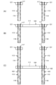
- a precast concrete column member 113 made of reinforced concrete that constitutes the column 3 has a main reinforcing bar 117 and a joint part 121 at the top. Further, the column member 113 has a hollow structure defining a hollow portion 114 therein.
- the worker places the column member 113 in a predetermined position using a crane or the like.
- the worker places cast-in-place concrete 116 in the hollow portion 114 of the column member 113 to construct a cast-in-place concrete section.
- the worker places the beam member 111 that constitutes a part of the beam 104 between the two joint parts 121, and attaches the beam member 111 to the joint of the column member 113 using an unbonded tendon (not shown). 121.
- a worker uses a crane or the like to add a new column member 113 to the already constructed column member. 113 at a predetermined position. At this time, the worker inserts the upper end of the main reinforcement 117 of the constructed column member 113 into a sleeve (not shown) embedded in the lower end of the new column member 113. After adjusting the position of the new column member 113, the worker injects joint grout between the lower surface of the new column member 113, the upper surface of the cast-in-place concrete 116 directly below it, and the upper surface of the joint section 121. , filling the sleeve with fitting grout.
- the column member 113 has a hollow structure including a hollow portion 114, and is lighter than a solid structure. Therefore, the number of pieces that can be transported per truck increases and can be lifted with a relatively small crane. In particular, when it comes to pillar members 113 for large logistics facilities, if it had a solid structure, only one member could be loaded on one truck, but two pillar members 113 can be loaded on one truck, improving transportation efficiency. improves. Additionally, since it can be lifted with a small crane, it is advantageous for construction in urban areas.
- the column members 113 are joined by sleeves or cast-in-place concrete 116, the members of the columns 103 cannot be reused when the building 1 is demolished.
- the beam member 111 is joined to the column member 113 by the unbonded tendon, it can be separated from the column member 113 and reused by releasing the connection by the unbonded tendon.
- the present invention is not limited to the above-described embodiments and modifications, and can be implemented in a wide range of modifications.
- the structure of the frames 2 and 102, the joint structure, etc. are not limited to the above example.
- a part of the frames 2 and 102 may include a member that does not include concrete, such as a steel frame member.
- each precast member only needs to contain precast concrete, and is not limited to the one made of the above-mentioned reinforced concrete.
- the specific configuration, arrangement, quantity, and material of each member or portion, or the order and method of work or processing, etc. may be changed as appropriate without departing from the spirit of the present invention.
- some or all of the configurations may be combined with each other.
- all of the constituent elements shown in the above embodiments are not necessarily essential and can be selected as appropriate.
Landscapes
- Engineering & Computer Science (AREA)
- Architecture (AREA)
- Physics & Mathematics (AREA)
- Electromagnetism (AREA)
- Civil Engineering (AREA)
- Structural Engineering (AREA)
- Aviation & Aerospace Engineering (AREA)
- General Physics & Mathematics (AREA)
- Rod-Shaped Construction Members (AREA)
Abstract
Description
まず、図1~図8を参照して本発明の第1実施形態について説明する。図1に示されるように、建物1(図6参照)の架構2は、水平面上で交差するX方向及びY方向に所定の間隔を空けて互いに離間するように配置された強化コンクリートからなる複数の柱3を含む。本実施形態では、柱3はX方向に3列以上に、Y方向に2列に配置されている。よって、X方向の端部に配置される4本の柱3は全て隅柱である。
図10は第2実施形態に係るプレキャスト部材及び建物1の再利用方法の解体時のフロー図であり、図9に対応する。図10に示すように、本実施形態では、ステップST21において建物1が解体される際に、監視装置60は各プレキャスト部材の再利用可否判定を実行し、プレキャスト部材の再利用可能性を判定する(ステップST22)。具体的には、監視装置60は、センサ55により検出された物理量Pが所定の第1基準値Pth1以内であるか否かを判定し、物理量Pが前記第1基準値Pth1以内である場合に再利用可能であると判定する。
次に、図11を参照して本発明の第3実施形態について説明する。なお、第1実施形態と同一又は同様の要素には同一の符号又は100を加えた符号を付し、重複する説明は省略する。
2 :架構
2X :X方向架構
2Y :Y方向架構
3 :柱
4 :第1梁
5 :第2梁
11 :第1梁部材(プレキャスト部材)
12 :第2梁部材(プレキャスト部材)
13 :柱部材(プレキャスト部材)
26 :第1アンボンド緊張材
36 :第2アンボンド緊張材
46 :第3アンボンド緊張材
50 :内装ユニット
55 :センサ
60 :監視装置
61 :演算処理装置
62 :記憶装置
100 :再利用評価システム
102 :架構
103 :柱
104 :梁
111 :梁部材(プレキャスト部材)
113 :柱部材(プレキャスト部材)
114 :中空部
116 :コンクリート
Claims (10)
- ラーメン構造の建物の架構を構成し且つプレキャストコンクリートを含むプレキャスト部材の再利用方法であって、
複数の柱部材及び複数の梁部材を含む複数の前記プレキャスト部材を備える前記建物を建設する際に、前記プレキャスト部材のうち、アンボンド緊張材によって他の前記プレキャスト部材に接合される少なくとも1つの前記プレキャスト部材に、所定の物理量を検出するセンサを取り付けるステップと、
前記建物の使用中、前記センサによって検出された前記プレキャスト部材の前記物理量を監視するステップと、
前記建物を解体する際に、前記センサの検出結果に基づいて前記プレキャスト部材の再利用可能性を判定するステップと、
再利用可能と判定された前記プレキャスト部材を、建設される他の建物に再利用するステップとを含む、建物のプレキャスト部材の再利用方法。 - 前記センサを取り付けるステップでは、前記梁部材が前記アンボンド緊張材によって前記柱部材に接合される前記建物を建設する際に、前記センサを前記梁部材に取り付け、
前記プレキャスト部材の再利用可能性を判定するステップでは、前記建物を解体する際に、前記梁部材の再利用可能性を判定する、請求項1に記載の建物のプレキャスト部材の再利用方法。 - 前記柱部材が中空構造を有し、前記建物を建設する際に、前記柱部材の所定位置への建て込み後に前記柱部材の中空部に現場打ちコンクリートが打設される請求項2に記載の建物のプレキャスト部材の再利用方法。
- 再利用可能と判定された前記梁部材に、外観上の異常があるか否かを目視によって検査するステップを更に含み、外観上の異常がない場合のみに再利用可能と判定する、請求項1~3のいずれか1項に記載の建物のプレキャスト部材の再利用方法。
- 前記建物を解体した後に前記プレキャスト部材に対する所定の検査を行い、前記センサの検出結果及び前記所定の検査の結果に基づいて、前記プレキャスト部材の損傷度合いを判定するステップと、
前記損傷度合いに応じて前記プレキャスト部材を再利用可能な状態に補修するステップと、を更に含む請求項1~3のいずれか1項に記載の建物のプレキャスト部材の再利用方法。 - ラーメン構造の架構を構成し且つプレキャストコンクリートを含むプレキャスト部材及び前記架構内に配置される複数の内装ユニットを含む建物の再利用方法であって、
複数の柱部材及び複数の梁部材を含む複数の前記プレキャスト部材を備える前記架構を建設する際に、前記プレキャスト部材のうち、アンボンド緊張材によって他の前記プレキャスト部材に接合される少なくとも1つの前記プレキャスト部材に、所定の物理量を検出するセンサを取り付けるステップと、
前記建物の使用中、前記センサによって検出された前記プレキャスト部材の前記物理量を監視するステップと、
前記建物を解体した後に前記プレキャスト部材に対する所定の検査を行い、前記センサの検出結果及び前記所定の検査の結果に基づいて、前記プレキャスト部材の損傷度合いを判定するステップと、
前記損傷度合いに応じて前記プレキャスト部材を補修するステップと、
前記内装ユニットの再利用可否に関する項目を点検するステップと、
前記プレキャスト部材を、建設される他の建物に再利用するステップと、
前記内装ユニットを他の建物に再利用するステップとを含む、建物の再利用方法。 - 前記建物の所定の区画を期間制限付きの利用に供するステップを更に含む請求項6に記載の建物の再利用方法。
- ラーメン構造の建物の架構を構成し且つプレキャストコンクリートを含むプレキャスト部材の再利用可能性を評価するための再利用評価システムであって、
複数の柱部材及び複数の梁部材を含む複数の前記プレキャスト部材を備える前記建物の、アンボンド緊張材によって他のプレキャスト部材に接合された少なくとも1つの前記プレキャスト部材に取り付けられて、所定の物理量を測定するセンサと、
前記センサの検出結果を記憶する記憶装置を含み、前記建物の使用中に前記プレキャスト部材の前記物理量を前記記憶装置に記憶させ、前記物理量を監視する監視装置とを備え、
前記監視装置が、前記センサの前記検出結果に基づいて前記プレキャスト部材の再利用可能性を判定するように構成されている、建物のプレキャスト部材の再利用評価システム。 - 前記監視装置は、前記センサにより検出された前記物理量が所定の第1基準値以内であるか否かを判定し、前記物理量が前記第1基準値以内である場合に再利用可能であると判定する、請求項8に記載の建物のプレキャスト部材の再利用評価システム。
- 前記監視装置は、前記建物の使用中に前記プレキャスト部材の前記物理量が前記第1基準値よりも大きな第2基準値を超えた場合に、部材交換が必要であると判定する、請求項9に記載の建物のプレキャスト部材の再利用評価システム。
Priority Applications (3)
| Application Number | Priority Date | Filing Date | Title |
|---|---|---|---|
| JP2024514921A JPWO2023199821A1 (ja) | 2022-04-13 | 2023-04-05 | |
| US18/854,635 US20250354890A1 (en) | 2022-04-13 | 2023-04-05 | Reuse method for precast members of building, reuse method for building, and reuse evaluation system for precast members of building |
| EP23788240.2A EP4509680A4 (en) | 2022-04-13 | 2023-04-05 | METHOD FOR REUSING A PREFABRICATED ELEMENT OF A BUILDING, METHOD FOR REUSING A BUILDING, AND EVALUATION SYSTEM FOR REUSING A PREFABRICATED ELEMENT OF A BUILDING |
Applications Claiming Priority (2)
| Application Number | Priority Date | Filing Date | Title |
|---|---|---|---|
| JP2022-066052 | 2022-04-13 | ||
| JP2022066052 | 2022-04-13 |
Publications (1)
| Publication Number | Publication Date |
|---|---|
| WO2023199821A1 true WO2023199821A1 (ja) | 2023-10-19 |
Family
ID=88329696
Family Applications (1)
| Application Number | Title | Priority Date | Filing Date |
|---|---|---|---|
| PCT/JP2023/014076 Ceased WO2023199821A1 (ja) | 2022-04-13 | 2023-04-05 | 建物のプレキャスト部材の再利用方法、建物の再利用方法及び、建物のプレキャスト部材の再利用評価システム |
Country Status (4)
| Country | Link |
|---|---|
| US (1) | US20250354890A1 (ja) |
| EP (1) | EP4509680A4 (ja) |
| JP (1) | JPWO2023199821A1 (ja) |
| WO (1) | WO2023199821A1 (ja) |
Citations (6)
| Publication number | Priority date | Publication date | Assignee | Title |
|---|---|---|---|---|
| JP2006144344A (ja) * | 2004-11-18 | 2006-06-08 | Ohbayashi Corp | コンクリート構造物及びコンクリート構造物の解体方法 |
| JP2010242418A (ja) * | 2009-04-08 | 2010-10-28 | Takenaka Komuten Co Ltd | プレキャスト鉄筋コンクリート部材を再利用するための接合構造及び同接合構造の解体工法 |
| JP2012172476A (ja) * | 2011-02-24 | 2012-09-10 | Taisei Corp | プレキャストコンクリート部材の連結構造および再生方法 |
| JP2017089225A (ja) * | 2015-11-10 | 2017-05-25 | 前田建設工業株式会社 | プレキャストコンクリートブロックを用いた建築構法 |
| JP2021161717A (ja) | 2020-03-31 | 2021-10-11 | 株式会社フジタ | コンクリート柱体、コンクリート柱、および構造体 |
| JP2022040423A (ja) * | 2020-08-29 | 2022-03-11 | 大成建設株式会社 | 構造物およびその構築方法 |
Family Cites Families (2)
| Publication number | Priority date | Publication date | Assignee | Title |
|---|---|---|---|---|
| CN106368381A (zh) * | 2016-09-18 | 2017-02-01 | 深圳大学 | 受弯构件及制作方法、建筑物裂缝修复系统及使用方法 |
| JP7285202B2 (ja) * | 2019-11-28 | 2023-06-01 | 三井住友建設株式会社 | 架構構造及びこれを備えた建物 |
-
2023
- 2023-04-05 JP JP2024514921A patent/JPWO2023199821A1/ja active Pending
- 2023-04-05 US US18/854,635 patent/US20250354890A1/en active Pending
- 2023-04-05 WO PCT/JP2023/014076 patent/WO2023199821A1/ja not_active Ceased
- 2023-04-05 EP EP23788240.2A patent/EP4509680A4/en active Pending
Patent Citations (6)
| Publication number | Priority date | Publication date | Assignee | Title |
|---|---|---|---|---|
| JP2006144344A (ja) * | 2004-11-18 | 2006-06-08 | Ohbayashi Corp | コンクリート構造物及びコンクリート構造物の解体方法 |
| JP2010242418A (ja) * | 2009-04-08 | 2010-10-28 | Takenaka Komuten Co Ltd | プレキャスト鉄筋コンクリート部材を再利用するための接合構造及び同接合構造の解体工法 |
| JP2012172476A (ja) * | 2011-02-24 | 2012-09-10 | Taisei Corp | プレキャストコンクリート部材の連結構造および再生方法 |
| JP2017089225A (ja) * | 2015-11-10 | 2017-05-25 | 前田建設工業株式会社 | プレキャストコンクリートブロックを用いた建築構法 |
| JP2021161717A (ja) | 2020-03-31 | 2021-10-11 | 株式会社フジタ | コンクリート柱体、コンクリート柱、および構造体 |
| JP2022040423A (ja) * | 2020-08-29 | 2022-03-11 | 大成建設株式会社 | 構造物およびその構築方法 |
Non-Patent Citations (1)
| Title |
|---|
| See also references of EP4509680A4 |
Also Published As
| Publication number | Publication date |
|---|---|
| EP4509680A1 (en) | 2025-02-19 |
| JPWO2023199821A1 (ja) | 2023-10-19 |
| US20250354890A1 (en) | 2025-11-20 |
| EP4509680A4 (en) | 2025-09-03 |
Similar Documents
| Publication | Publication Date | Title |
|---|---|---|
| EP2966232B1 (en) | Dry joint joining device between columns and beams of precast reinforced concrete | |
| Negro et al. | Design guidelines for connections of precast structures under seismic actions | |
| JP7285202B2 (ja) | 架構構造及びこれを備えた建物 | |
| Pul et al. | Experimental and numerical investigation of a proposed monolithic-like precast concrete column-foundation connection | |
| JP6747734B1 (ja) | Pc造3軸圧縮柱梁接合部のプレストレス導入法 | |
| Rajanayagam et al. | Evaluation of inter-modular connection behaviour under lateral loads: An experimental and numerical study | |
| Lee et al. | Connecting performance evaluation of the Quick-Connector for modular steel construction | |
| WO2023199821A1 (ja) | 建物のプレキャスト部材の再利用方法、建物の再利用方法及び、建物のプレキャスト部材の再利用評価システム | |
| Asif et al. | Analysis of steel–concrete composite beam using Ansys 18.1 Workbench | |
| KR101045821B1 (ko) | 내진 보강용 브레이스 조립체 시공공법 | |
| JP6717782B2 (ja) | 既設フーチングの補強方法 | |
| KR102453459B1 (ko) | 플랜지 결합부를 구비한 결합조립체를 이용한 기둥-보의 결합구조 및 기둥-보 시공방법 | |
| JP6683336B1 (ja) | 建物構造及び建物構造の形成方法 | |
| JP3772247B2 (ja) | 既存大梁の曲げに対する耐震補強方法 | |
| Septiarsilia et al. | Hybrid beam-column connection of precast concrete structures: a review | |
| JP2025082071A (ja) | プレキャストプレストレストコンクリート部材 | |
| CN121781690A (zh) | 预制建筑结构件 | |
| CN114936400A (zh) | 一种基于bim技术的超高悬空大跨度单梁的施工方法 | |
| JP2018150722A (ja) | 柱梁接合構造及び柱梁接合構造の形成方法 | |
| JP3810007B2 (ja) | 住宅の鉄骨構造及び施工方法 | |
| CN224002334U (zh) | 一种适用于柱或梁现浇施工的预制建筑模板 | |
| JP2003105716A (ja) | 角形鋼管を主桁に用いた橋梁構造 | |
| Febriawan et al. | Alternative Design of Menara 17 Structure in Surabaya with Castellated Steel Beam | |
| Fisher | Strengthening open-web steel joists | |
| Kroyer | Development and validation of component-based finite element models for shallow floor composite beams |
Legal Events
| Date | Code | Title | Description |
|---|---|---|---|
| 121 | Ep: the epo has been informed by wipo that ep was designated in this application |
Ref document number: 23788240 Country of ref document: EP Kind code of ref document: A1 |
|
| ENP | Entry into the national phase |
Ref document number: 2024514921 Country of ref document: JP Kind code of ref document: A |
|
| WWE | Wipo information: entry into national phase |
Ref document number: 18854635 Country of ref document: US |
|
| WWE | Wipo information: entry into national phase |
Ref document number: 2023788240 Country of ref document: EP |
|
| NENP | Non-entry into the national phase |
Ref country code: DE |
|
| ENP | Entry into the national phase |
Ref document number: 2023788240 Country of ref document: EP Effective date: 20241113 |
|
| WWP | Wipo information: published in national office |
Ref document number: 18854635 Country of ref document: US |