WO2023204182A1 - 制振装置およびそれを用いた密閉型圧縮機 - Google Patents
制振装置およびそれを用いた密閉型圧縮機 Download PDFInfo
- Publication number
- WO2023204182A1 WO2023204182A1 PCT/JP2023/015344 JP2023015344W WO2023204182A1 WO 2023204182 A1 WO2023204182 A1 WO 2023204182A1 JP 2023015344 W JP2023015344 W JP 2023015344W WO 2023204182 A1 WO2023204182 A1 WO 2023204182A1
- Authority
- WO
- WIPO (PCT)
- Prior art keywords
- elastic member
- vibration damping
- holding member
- contact
- damping device
- Prior art date
- Legal status (The legal status is an assumption and is not a legal conclusion. Google has not performed a legal analysis and makes no representation as to the accuracy of the status listed.)
- Ceased
Links
Images



Classifications
-
- F—MECHANICAL ENGINEERING; LIGHTING; HEATING; WEAPONS; BLASTING
- F04—POSITIVE - DISPLACEMENT MACHINES FOR LIQUIDS; PUMPS FOR LIQUIDS OR ELASTIC FLUIDS
- F04B—POSITIVE-DISPLACEMENT MACHINES FOR LIQUIDS; PUMPS
- F04B39/00—Component parts, details, or accessories, of pumps or pumping systems specially adapted for elastic fluids, not otherwise provided for in, or of interest apart from, groups F04B25/00 - F04B37/00
- F04B39/0027—Pulsation and noise damping means
- F04B39/0044—Pulsation and noise damping means with vibration damping supports
-
- F—MECHANICAL ENGINEERING; LIGHTING; HEATING; WEAPONS; BLASTING
- F04—POSITIVE - DISPLACEMENT MACHINES FOR LIQUIDS; PUMPS FOR LIQUIDS OR ELASTIC FLUIDS
- F04B—POSITIVE-DISPLACEMENT MACHINES FOR LIQUIDS; PUMPS
- F04B35/00—Piston pumps specially adapted for elastic fluids and characterised by the driving means to their working members, or by combination with, or adaptation to, specific driving engines or motors, not otherwise provided for
- F04B35/04—Piston pumps specially adapted for elastic fluids and characterised by the driving means to their working members, or by combination with, or adaptation to, specific driving engines or motors, not otherwise provided for the means being electric
-
- F—MECHANICAL ENGINEERING; LIGHTING; HEATING; WEAPONS; BLASTING
- F04—POSITIVE - DISPLACEMENT MACHINES FOR LIQUIDS; PUMPS FOR LIQUIDS OR ELASTIC FLUIDS
- F04B—POSITIVE-DISPLACEMENT MACHINES FOR LIQUIDS; PUMPS
- F04B39/00—Component parts, details, or accessories, of pumps or pumping systems specially adapted for elastic fluids, not otherwise provided for in, or of interest apart from, groups F04B25/00 - F04B37/00
- F04B39/0027—Pulsation and noise damping means
-
- F—MECHANICAL ENGINEERING; LIGHTING; HEATING; WEAPONS; BLASTING
- F04—POSITIVE - DISPLACEMENT MACHINES FOR LIQUIDS; PUMPS FOR LIQUIDS OR ELASTIC FLUIDS
- F04B—POSITIVE-DISPLACEMENT MACHINES FOR LIQUIDS; PUMPS
- F04B39/00—Component parts, details, or accessories, of pumps or pumping systems specially adapted for elastic fluids, not otherwise provided for in, or of interest apart from, groups F04B25/00 - F04B37/00
- F04B39/02—Lubrication
- F04B39/0223—Lubrication characterised by the compressor type
- F04B39/023—Hermetic compressors
-
- F—MECHANICAL ENGINEERING; LIGHTING; HEATING; WEAPONS; BLASTING
- F16—ENGINEERING ELEMENTS AND UNITS; GENERAL MEASURES FOR PRODUCING AND MAINTAINING EFFECTIVE FUNCTIONING OF MACHINES OR INSTALLATIONS; THERMAL INSULATION IN GENERAL
- F16F—SPRINGS; SHOCK-ABSORBERS; MEANS FOR DAMPING VIBRATION
- F16F15/00—Suppression of vibrations in systems; Means or arrangements for avoiding or reducing out-of-balance forces, e.g. due to motion
- F16F15/02—Suppression of vibrations of non-rotating, e.g. reciprocating systems; Suppression of vibrations of rotating systems by use of members not moving with the rotating systems
- F16F15/04—Suppression of vibrations of non-rotating, e.g. reciprocating systems; Suppression of vibrations of rotating systems by use of members not moving with the rotating systems using elastic means
- F16F15/06—Suppression of vibrations of non-rotating, e.g. reciprocating systems; Suppression of vibrations of rotating systems by use of members not moving with the rotating systems using elastic means with metal springs
Definitions
- the present invention provides a vibration damping device capable of reducing, alleviating, or suppressing the vibration of the structure in a device that includes a structure that generates vibration, and a closed type device that is a typical example of a device using the vibration device.
- a vibration damping device capable of reducing, alleviating, or suppressing the vibration of the structure in a device that includes a structure that generates vibration, and a closed type device that is a typical example of a device using the vibration device.
- vibration damping techniques when vibrations occur during the operation of equipment, techniques for reducing, alleviating, or suppressing the vibrations (vibration damping techniques) have been studied.
- vibration propagates from an excitation source that causes vibration to a specific object (structure) when the frequency of the vibration from the excitation source overlaps with the resonant frequency of the object to be propagated, make a lot of noise. Therefore, reducing, alleviating, or suppressing vibrations (vibration damping action) can also serve as a noise countermeasure.
- An example of a device that generates vibrations is a hermetic compressor.
- a compression mechanism such as a reciprocating type, a rotary type, a scroll type, etc. is housed inside an airtight container.
- a compression operation is performed in which the refrigerant is sucked, compressed, and discharged by the compression mechanism.
- Pulsations are generated during this compression operation, and the pulsations are propagated to the closed container via the refrigerant gas or lubricating oil present in the closed container, and the closed container is excited to generate vibrations.
- the frequency of this vibration depends on the operating speed of the compression mechanism.
- noise such as a tapping sound is generated from the suction/discharge valve included in the compression mechanism. This noise is also transmitted to the closed container via the solid contact portion of the compression mechanism and becomes vibration.
- noise such as banging sounds has harmonics that fall within the human audible range, and when such harmonic sounds (vibrations) are transmitted to a closed container, they vibrate the closed container, causing further noise generation. It may lead to.
- Patent Document 1 discloses a method of directly fixing an elastic member to a closed container of a closed compressor.
- Patent Document 2 discloses a method using a vibration damping member having a contact portion that elastically contacts the surface of a closed container.
- an elastic member is fixed to the inner surface of a closed container and brought into elastic contact with the elastic member, thereby obtaining a contact friction damping effect in a relatively wide frequency band.
- a damping plate 102 having a plurality of contact parts 104a to 104f is fixed by welding to a fixed part 103 to a sealed container 101. There is. This damping plate 102 corresponds to an elastic member.
- Patent Document 2 the method disclosed in Patent Document 1 in which an elastic member (damping plate 102) is fixed to a structure (airtight container 101) and brought into elastic contact with the structure , a sufficient noise prevention effect may not be obtained.
- This vibration damping member 202 includes a plurality of contact portions 205a to 205d whose portions other than the free end 203 come into elastic contact with the surface of the closed container 201. Thereby, the natural frequency of the free end 203 of the vibration damping member 202 can be made to substantially match the natural frequency of the closed container 201, so that a good vibration damping effect can be achieved.
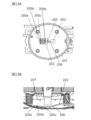
- FIGS. 13A and 13B illustrate a configuration in which the damping member 202 is provided on the bottom surface of the closed container 201, and the damping member 202 is immersed in lubricating oil 207.
- the damping member 202 disclosed in Patent Document 2 is specialized for application to hermetic compressors. Therefore, its configuration is relatively complex, including a plurality of contact parts 205a to 205d and a free end 203 via a connecting part 206. Therefore, there is a need for a vibration damping device with a simple configuration that can be applied not only to the field of hermetic compressors but also to other fields.
- the present invention was made to solve these problems, and is applicable not only to the field of hermetic compressors but also to other fields, and is capable of realizing a good vibration damping effect.
- the present invention aims to provide a vibration damping device and a hermetic compressor using the vibration damping device.
- a vibration damping device includes a plate-shaped elastic member having elasticity that can be deformed so as to come into contact with the surface of a structure where vibrations are generated, and a plate-shaped elastic member having elasticity that is a holding member that is held in contact with the body surface, the holding member is partially fixed with a predetermined distance between the holding member and the structure surface, and the elastic member is The member is held between the member and the surface of the structure, and is in contact with the surface of the structure without being fixed.
- the plate-shaped elastic member is held by the holding member so as to be in contact with the surface of the structure, but the elastic member is not fixed to the surface of the structure but is in contact with the structure. Become. Thereby, the elastic member is maintained in a state in which it is not fixed but in contact with the structure where vibrations occur. As a result, even if vibration occurs in the structure, the vibration is satisfactorily suppressed or alleviated by the elastic action of the elastic member.
- the elastic member is held between a holding member that is partially fixed to the surface of the structure, and is in contact with the surface of the structure. Therefore, it is possible to realize a vibration damping device with a simple configuration without the need to adopt a complicated configuration.
- the contactability of the elastic member to the structure surface depends on the elasticity of the elastic member, and the contact range of the elastic member to the structure surface depends on the area of the elastic member. Since the elastic member is a plate member having elasticity, it is possible to easily adjust the contact property or the contact range of the elastic member. This makes it possible to easily achieve vibration damping performance that corresponds to the vibrations generated in the structure.
- the hermetic compressor according to the present invention includes a hermetic container, an electric element including a stator and a rotor, and a compression element that is driven by the electric element and compresses a fluid.
- the electric element and the compression element are housed in the sealed container, and lubricating oil is stored in the sealed container, further comprising a vibration damping device attached to an inner surface of the sealed container.
- the vibration damping device includes a plate-shaped elastic member having elasticity that is deformable so as to be in contact with the inner surface of the sealed container, and a holding member that holds the elastic member in close contact with the inner surface of the sealed container.
- the member is partially fixed with a predetermined gap between the member and the inner surface of the sealed container, and the elastic member is held between the holding member and the inner surface of the sealed container, It has a configuration in which it is not fixed to but in contact with the surface of the structure.
- the damping device is provided with a structure in which the plate-shaped elastic member is held by the holding member so as to be in contact with the airtight container without being fixed to the airtight container.
- the vibration damping device included in the hermetic compressor can exhibit a friction damping effect even against three-dimensional vibrations of the hermetic container. Therefore, it is possible to attenuate the peaks of a plurality of resonance frequencies of the closed container. Therefore, for example, if the hermetic compressor is a reciprocating type, the noise in the harmonic resonance frequency band specific to the reciprocating type can be reliably reduced.
- the present invention provides a vibration damping device that can be applied not only to the field of hermetic compressors but also other fields and can realize a good vibration damping effect, and the vibration damping device. This has the effect that it is possible to provide a hermetic compressor using the same method.
- FIG. 1 is a sectional view showing a configuration example of a hermetic compressor according to an embodiment of the present disclosure.
- FIG. 2 is a plan view showing an example of the structure of the inner surface of an upper hermetic container of the hermetic container of the hermetic compressor shown in FIG.
- FIG. 3 is a partial sectional view showing a configuration example of the vibration damping device according to the present embodiment, which is provided in the upper closed container shown in FIG.
- FIG. 4 is a plan view showing an example of the structure of the inner surface of the lower hermetic container of the hermetic container of the hermetic compressor shown in FIG.
- FIG. 5 is a partial sectional view showing a configuration example of the vibration damping device according to the present embodiment, which is provided in the lower sealed container shown in FIG. FIG.
- FIG. 6 is a schematic process diagram showing a method of attaching the vibration damping device provided in the upper closed container shown in FIG. 2.
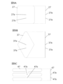
- FIG. 7A is a comparative view of a plane and a cross section showing an example of a holding member included in the vibration damping device shown in FIG. 3 or 5, and FIG. 7B and FIG.
- FIG. 8A is a comparative view of a plane and a cross section of an example of the elastic member included in the vibration damping device shown in FIG. 3 or 5, and FIG. 8B is an example of a positioning protrusion included in the elastic member shown in FIG. 8A.
- FIG. 9A to 9C are comparative views of a plane and a cross section showing other examples of the elastic member shown in FIG. 8A.
- FIG. 10A is a graph showing the relationship between vibration level and frequency in representative examples and comparative examples of the present disclosure
- FIG. 10B is a graph showing the relationship between noise level and frequency in the same example and the same comparative example. It is a graph.
- FIG. 11A is a graph showing the relationship between vibration level and frequency in other representative examples and comparative examples of the present disclosure
- FIG. 11B is a graph showing the relationship between noise level and frequency in the same example and the same comparative example. This is a graph showing.
- FIG. 12 is a perspective view showing an example of an elastic member included in the hermetic compressor described in Patent Document 1.
- FIG. 12 is a perspective view showing an example of an elastic member included in the hermetic compressor described in Patent Document 1.
- FIG. 13A is a top view showing an example of a configuration in which the vibration damping member included in the hermetic compressor described in Patent Document 2 is provided on the bottom surface of a closed container
- FIG. 13B is a top view showing an example of a structure in which the vibration damping member shown in FIG.
- FIG. 3 is a partial cross-sectional view showing a state of being immersed in lubricating oil.
- a vibration damping device includes a plate-shaped elastic member having elasticity that is deformable so as to come into contact with the surface of a structure where vibrations occur, and the elastic member is held in contact with the surface of the structure.
- a holding member the holding member is partially fixed with a predetermined distance between the holding member and the surface of the structure, and the elastic member is fixed between the holding member and the surface of the structure. In this configuration, the structure is held in a state where it is in contact with the surface of the structure without being fixed to it.
- the plate-shaped elastic member is held by the holding member so as to be in contact with the surface of the structure, but the elastic member is not fixed to the surface of the structure but is in contact with the structure. Become. Thereby, the elastic member is maintained in a state in which it is not fixed but in contact with the structure where vibrations occur. As a result, even if vibration occurs in the structure, the vibration is satisfactorily suppressed or alleviated by the elastic action of the elastic member.
- the elastic member is held between a holding member that is partially fixed to the surface of the structure, and is in contact with the surface of the structure. Therefore, it is possible to realize a vibration damping device with a simple configuration without the need to adopt a complicated configuration.
- the contactability of the elastic member to the structure surface depends on the elasticity of the elastic member, and the contact range of the elastic member to the structure surface depends on the area of the elastic member. Since the elastic member is a plate member having elasticity, it is possible to easily adjust the contact property or the contact range of the elastic member. This makes it possible to easily achieve vibration damping performance that corresponds to the vibrations generated in the structure.
- the surface of the structure may be curved
- the holding member may include a portion having a curvature corresponding to the curvature of the surface of the structure.
- the shape of the corner or longitudinal end of the plate-shaped elastic member may be a convex curved shape.
- a plurality of protrusions are provided on a non-contact surface that is a surface on the side that does not contact the structure surface among both surfaces of the elastic member, and the holding member is provided with a plurality of protrusions.
- a configuration may be adopted in which holes are provided at respective positions corresponding to the plurality of projections.
- the holding member may have a plate-like portion that holds the elastic member, and the thickness thereof may be larger than the thickness of the elastic member.
- the holding member may be configured to hold the elastic member in a biased state toward the surface of the structure.
- the elastic member may be made of metal and may be hardened.
- the structure may be a hermetic container included in a hermetic compressor, and the inner surface of the hermetic container may be the surface of the structure.
- a hermetic compressor includes a hermetic container, an electric element including a stator and a rotor, and a compression element that is driven by the electric element and compresses a fluid, the electric element and the compressor.
- the element is housed in the sealed container, lubricating oil is stored in the sealed container, and a vibration damping device is attached to the inner surface of the sealed container, and the vibration damping device is attached to the inner surface of the sealed container.
- a plate-shaped elastic member having elasticity that can be deformed so as to be in contact with the inner surface of the sealed container; and a holding member that holds the elastic member in close contact with the inner surface of the sealed container, the holding member having contact with the inner surface of the sealed container.
- the elastic member is partially fixed with a predetermined gap therebetween, and the elastic member is held between the holding member and the inner surface of the sealed container without being fixed to the surface of the structure. This is a configuration in which they are in contact with each other.
- the damping device is provided with a structure in which the plate-shaped elastic member is held by the holding member so as to be in contact with the airtight container without being fixed to the airtight container.
- the vibration damping device included in the hermetic compressor can exhibit a friction damping effect even against three-dimensional vibrations of the hermetic container. Therefore, it is possible to attenuate the peaks of a plurality of resonance frequencies of the closed container. Therefore, for example, if the hermetic compressor is a reciprocating type, the noise in the harmonic resonance frequency band specific to the reciprocating type can be reliably reduced.
- the vibration damping device may be attached to at least one of an upper inner surface and a lower inner surface within the hermetic container.
- FIG. 1 is a cross-sectional view showing a configuration example of a hermetic compressor according to a typical embodiment of the present disclosure.
- the hermetic compressor has a structure in which an electric element 2 and a compression element 3 are housed in a hermetic container 1.
- the electric element 2 and the compression element 3 constitute a compressor main body 4.
- a hermetic container 1 is filled with refrigerant gas 6, in this embodiment, for example, R600a, and a lubricating oil 7, in this embodiment, for example, mineral oil is stored at the bottom.
- the compressor main body 4 housed in the closed container 1 is elastically supported by a suspension spring 5.
- the sealed container 1 is composed of an upper sealed container 1a and a lower sealed container 1b.
- the lower sealed container 1b is provided with a spring receiving portion 5a, a suspension spring 5 is attached to the spring receiving portion 5a, and the compressor main body 4 is supported by the suspension spring 5.
- the sealed container 1 (the upper sealed container 1a and the lower sealed container 1b) is formed by drawing an iron plate, for example.
- the closed container 1 is equipped with an intake pipe 8 and a discharge pipe 9.
- One end of the suction pipe 8 communicates with the inside of the closed container 1, and the other end is connected to the low pressure side (not shown) of the refrigeration system.
- One end of the discharge pipe 9 passes through the closed container 1 and communicates with a discharge muffler (not shown) from the compression element 3, and the other end is connected to the high pressure side (not shown) of the refrigeration system.
- the electric element 2 is composed of at least a rotor 14 and a stator 15.
- the stator 15 is arranged on the outer diameter side of the rotor 14 so as to maintain a substantially constant gap with the rotor 14.
- the compression element 3 has a reciprocating configuration driven by the electric element 2, and includes a shaft (crankshaft) 10, a cylinder block 11, a piston 12, a connecting portion 13, and the like.
- the shaft 10 includes at least a main shaft, an eccentric shaft formed eccentrically with respect to the main shaft, and a flange portion connecting the main shaft and the eccentric shaft.
- the stator 15 is fixed to the leg portion of the cylinder block 11, and the rotor 14 is fixed to the main axis of the shaft 10 by shrink fitting, for example.
- the eccentric shaft of the shaft 10 is located above the hermetic compressor, and the main shaft is located below the hermetic compressor. Therefore, this vertical positional relationship (direction) is also used when explaining the position of the shaft 10.
- the upper end of the eccentric shaft is directed toward the inner upper surface of the closed container 1 (upper closed container 1a), and the lower end of the eccentric shaft is connected to the main shaft.
- the upper end of the main shaft is connected to the eccentric shaft, the lower end of the main shaft faces the inner lower surface of the sealed container 1 (lower sealed container 1b), and the lower end of the main shaft is immersed in lubricating oil 7. Further, an oil supply mechanism is provided below the shaft 10, that is, below the main shaft, and the oil supply mechanism supplies the lubricating oil 7 from the lower end of the main shaft immersed in the lubricating oil 7 to the upper end of the eccentric shaft.
- a cylinder that forms a compression chamber and a main bearing that rotatably supports the main axis of the shaft 10 are integrally formed in the cylinder block 11.
- the main bearing is formed in a tubular shape (cylindrical shape) extending vertically with respect to the cylinder block 11, and its inner circumferential surface is a sliding surface.
- the main bearing also includes a thrust surface and a tubular extension.
- the thrust surface is a flat portion that extends in a direction (perpendicular direction, horizontal direction) perpendicular to the extending direction (vertical direction) of the axis, that is, the main shaft.
- the tubular extension has a tubular shape (cylindrical shape) that extends further upward than the thrust surface, in other words, it is a portion that extends upward from the tubular main bearing body. Therefore, together with the main bearing body, the tubular extension has an inner circumferential surface (sliding surface) that faces the outer circumferential surface (sliding surface) of the main shaft.
- a thrust ball bearing is provided on the thrust surface of the main bearing.
- the cylinder block 11 is made of cast iron, for example.
- the compression chamber is a cylindrical bore formed in the cylinder block 11, and the piston 12 is reciprocatably inserted into the compression chamber. Therefore, the compression chamber is closed by the insertion of the piston 12.
- the connecting portion 13 is made of, for example, an aluminum casting, supports the eccentric shaft of the shaft 10, and is connected to the piston 12. Therefore, the eccentric axis of the shaft 10 and the piston 12 are connected by the connecting portion 13.
- this embodiment includes vibration damping devices 18 and 19 that are attached to the inner surface of the hermetic container 1 of the hermetic compressor.
- an upper vibration damping device 18 is provided on the inner surface of the upper sealed container 1a of the sealed container 1 (the upper inner surface of the sealed container 1)
- a lower damping device 18 is provided on the inner surface of the lower sealed container 1b (the lower inner surface of the sealed container 1).
- a shaking device 19 is provided. Note that these damping devices 18 and 19 will be described later.
- the electric element 2 is located on the upper side and the compression element 3 is located on the lower side.
- the configuration of the hermetic compressor according to the present disclosure is not limited to this, and the electric element 2 may be located on the lower side and the compression element 3 may be located on the upper side.
- the electric element 2 is of an inner rotor type, and the rotor 14 is coaxial with the stator 15 and rotatably arranged on the inner circumference of the stator 15.
- the configuration of the electric element 2 is not limited to this, and may be an outer rotor type, that is, the rotor 14 may be coaxial with the stator 15 and rotatably disposed around the outer periphery of the stator 15. .
- the compression element 3 is of a reciprocating type (reciprocating type), but the present disclosure is not limited thereto, and may be of a rotary type (rotating type), for example. .
- the hermetic compressor is such that the compression element 3 driven by the electric element 2 compresses the refrigerant gas 6 filled in the hermetic container 1, but the hermetic compressor according to the present disclosure is not limited to one that compresses refrigerant gas 6, but may also compress any known fluid other than refrigerant gas 6.
- the hermetic compressor having such a configuration is connected to, for example, a known refrigeration system to form a refrigerant circuit.
- the refrigerant circuit includes a hermetic compressor, a radiator, a pressure reducing device, and a heat absorber, and may have a configuration in which these are connected in a ring shape by piping.
- the hermetic compressor In order to operate the hermetic compressor, first, power is supplied to the electric element 2 from a commercial power source (not shown). This causes the rotor 14 of the electric element 2 to rotate. The rotor 14 rotates the shaft 10, and the eccentric movement of the eccentric shaft of the shaft 10 is transmitted to the piston 12 via the connecting portion 13, thereby driving the piston 12 to reciprocate within the compression chamber. A predetermined compression operation is performed in which the refrigerant gas 6 guided into the closed container 1 by the reciprocating motion of the piston 12 is sucked into the compression chamber and compressed.
- the reciprocating movement of the piston 12 draws refrigerant gas 6, which is the working fluid in the refrigeration system, into the closed container 1 through the suction pipe 8.
- Refrigerant gas 6 in the closed container 1 is sucked into a compression chamber via a suction valve, compressed, and discharged from a discharge pipe 9 to the high-pressure side of the refrigeration system via a discharge valve and a discharge muffler.
- the hermetic compressor pulsations occur in the flow of the refrigerant gas 6 due to the compression operation.
- the compressor main body 4 which is elastically supported by the closed container 1 by the suspension spring 5, also pulsates.
- the pulsation of the compressor body 4 is also caused by other vibrations.
- the closed container 1 is excited and vibrates. When the closed container 1 vibrates in this way, noise is generated.
- the vibration damping devices 18 and 19 are provided for the closed container 1 to reduce, alleviate, or suppress (dampen) the vibration of the closed container 1.
- the specific driving method of the hermetic compressor is not limited to the above-mentioned inverter driving.
- a hermetic compressor may be driven with simple on/off control.
- the operating frequency is not particularly limited either.
- the operating rotation speed of the electric element 2 is not particularly limited, but is generally within the range of, for example, 17 to 75 rps (revolutions per second or rotations per second).
- the upper limit of the operating rotation speed may be 80 rps, and the lower limit of the operating rotation speed may be 13 rps.
- FIG. 2 is a plan view showing the ceiling surface of the closed container 1, that is, the inner surface side of the upper closed container 1a.
- FIG. 3 is a partial cross-sectional view showing a typical configuration example of a vibration damping device according to the present disclosure, which is provided on the inner surface (ceiling surface) of the upper closed container 1a.
- FIG. 4 is a plan view showing the bottom surface of the closed container 1, that is, the inner surface of the lower closed container 1b.
- FIG. 5 is a partial sectional view showing a typical configuration example of a vibration damping device according to the present disclosure, which is provided on the inner surface (bottom surface) of the lower sealed container 1b.
- an upper vibration damping device 18 including a holding member 16 and an elastic member 17 is provided on the inner surface, that is, the ceiling surface (top surface) of the upper closed container 1a.
- the holding member 16 holds the plate-shaped elastic member 17 in contact with the surface of the upper sealed container 1a (structure). Therefore, in the example shown in FIG. 2, the holding member 16 has a plate-like configuration that can cover the entire elastic member 17. Therefore, in FIG. 2, the holding member 16 is illustrated in solid lines, and the elastic member 17 covered by the holding member 16 is illustrated in dotted lines.
- the holding member 16 has two positioning holes 16a and two fixing parts 16b.
- the holding member 16 is configured as a plate member having a longitudinal direction, has fixing portions 16b provided at both ends thereof, and has two positioning holes 16a formed side by side along the longitudinal direction near the center portion in the longitudinal direction. ing.
- the elastic member 17 is also configured as a plate member having a longitudinal direction.
- the elastic member 17 is entirely covered by the holding member 16, so the spread area of the elastic member 17 is smaller than the spread area of the holding member 16.
- Two positioning protrusions 17a are provided along the longitudinal direction at the center of the elastic member 17 in the longitudinal direction. The position of the positioning protrusion 17a of the elastic member 17 and the position of the positioning hole 16a of the holding member 16 correspond to each other.
- the other surface (the second surface, the back surface of the first surface) of the elastic member 17 is supported or urged by the holding member 16, and is held such that the first surface of the elastic member 17 is in contact with the upper closed container 1a. . Therefore, the first surface of the elastic member 17 is used as a "contact surface” that contacts the upper closed container 1a, that is, the surface of the structure where vibrations occur, and the second surface of the elastic member 17, that is, the upper closed container 1a is The surface on the non-contact side is defined as a "non-contact surface” that does not contact the structure.
- the positioning protrusion 17a is provided on the non-contact surface (second surface) of the elastic member 17.
- the holding member 16 holds the elastic member 17 so that the contact surface (first surface) of the elastic member 17 is in contact with the upper closed container 1a (structure), so unlike the elastic member 17 which has elasticity, the holding member 16 does not have rigidity.
- the structure in which vibrations occur is the closed container 1, and as shown in FIG. 1 or 3, the ceiling surface (structure surface) of the closed container 1 (upper closed container 1a) has a convex upper side. It is curved to . Therefore, the holding member 16 is also curved along the curve of the ceiling surface.
- first surface of the holding member 16 which is a plate member, contacts the elastic member 17 and holds the elastic member 17 in contact with the upper sealed container 1a (structure). Therefore, the first surface of the holding member 16 is a "holding surface” for holding the elastic member 17, and the second surface of the holding member 16, that is, the back surface of the holding surface, is a "non-holding surface” that does not hold the elastic member 17. shall be.
- the fixing parts 16b provided at both ends of the holding member 16 are parts for fixing the holding member 16 to the upper closed container 1a, and in this embodiment, are formed as protrusions that protrude toward the holding surface side.
- the holding member 16 Since the elastic member 17 is interposed between the holding member 16 and the surface of the upper sealed container 1a (structure), the holding member 16 has a predetermined space between it and the upper sealed container 1a (structure).
- the fixing portion 16b is partially fixed to the upper sealed container 1a by the fixing portion 16b, which is welded to the inner surface of the upper sealed container 1a.
- the positioning hole 16a of the holding member 16 is formed at a position corresponding to the positioning protrusion 17a of the elastic member 17. As a result, the positioning protrusion 17a enters the positioning hole 16a, so that the elastic member 17 is positioned relative to the holding member 16. Although the holding member 16 is fixed to the upper sealed container 1a, the elastic member 17 is only positioned by the holding member 16. Therefore, the elastic member 17 can contact the upper sealed container 1a in a positioned state without being fixed to the upper sealed container 1a.
- a flat plate (plate member) elastic member 17 is held between the upper sealed container 1a (structure) and the holding member 16.
- the holding member 16 has a holding surface that substantially matches the curvature of the upper sealed container 1a, and a gap at a predetermined interval is formed between the holding member 16 and the inner surface (ceiling surface) of the upper sealed container 1a. It is fixed to the upper closed container 1a as shown in FIG.
- the hermetic compressor according to the present embodiment includes an upper vibration damping device 18 on the ceiling surface of the hermetic container 1 (inner surface of the upper hermetic container 1a), and also includes an upper vibration damping device 18 on the bottom surface of the hermetic container 1 (inner surface of the upper hermetic container 1a).
- a lower vibration damping device 19 is provided on the inner surface of the closed container 1b.
- a lower vibration damping device 19 including a holding member 16 and an elastic member 17 is provided on the inner surface, that is, the bottom surface, of the lower sealed container 1b.
- the lower vibration damping device 19 also has the same configuration as the upper vibration damping device 18, so in FIG. is illustrated by the dotted line.
- Suspension springs 5 that support the compressor main body 4 are attached to the lower sealed container 1b, so for example, as shown in FIG. A receiving portion 5a is provided. Therefore, the lower vibration damping device 19 is attached at a position inside the square area so as not to overlap the position of the spring receiving portion 5a. Further, as shown in FIG. 1, lubricating oil 7 is stored in the lower sealed container 1b, and as shown in FIG. 4, a suction pipe 8, a discharge pipe 9, etc. are provided.
- the holding member 16 has two positioning holes 16a and two fixing portions 16b.
- the holding member 16 is configured as a plate member having a longitudinal direction, has fixing portions 16b provided at both ends thereof, and has two positioning holes 16a formed side by side along the longitudinal direction near the center portion in the longitudinal direction. ing.
- the elastic member 17 is also configured as a plate member having a longitudinal direction.
- the elastic member 17 is entirely covered by the holding member 16, so the spread area of the elastic member 17 is smaller than the spread area of the holding member 16.
- Two positioning protrusions 17a are provided along the longitudinal direction at the center of the elastic member 17 in the longitudinal direction. The position of the positioning protrusion 17a of the elastic member 17 and the position of the positioning hole 16a of the holding member 16 correspond to each other.
- the contact surface (first surface) of the elastic member 17 is in contact with the lower sealed container 1b, and the non-contact surface (second surface) of the elastic member 17 is
- the elastic member 17 is supported or urged by the holding member 16 and held so that the contact surface of the elastic member 17 is in contact with the lower sealed container 1b.
- the positioning protrusion 17a is provided on the non-contact surface of the elastic member 17.
- the holding member 16 holds the elastic member 17 using the holding surface (first surface) so that the contact surface of the elastic member 17 comes into contact with the lower sealed container 1b (structure).
- the bottom surface (structure surface) of the closed container 1 (lower closed container 1b) is curved convexly at the lower side. Therefore, the holding member 16 is also curved along the curve of the bottom surface.
- the fixing parts 16b provided at both ends of the holding member 16 are parts for fixing the holding member 16 to the lower sealed container 1b, and like the upper vibration damping device 18, protrude toward the holding surface (first surface) side. Formed as a protrusion.
- the holding member 16 Since the holding member 16 has an elastic member 17 interposed between it and the surface of the lower sealed container 1b (structure), the holding member 16 has a predetermined space between it and the lower sealed container 1b (structure). , is partially fixed to the lower sealed container 1b by the fixed part 16b. In this embodiment, similarly to the upper vibration damping device 18, the fixed part 16b is partially fixed to the inner surface of the lower sealed container 1b. be welded.
- the positioning hole 16a of the holding member 16 is formed at a position corresponding to the positioning protrusion 17a of the elastic member 17.
- the positioning protrusion 17a enters the positioning hole 16a, so that the elastic member 17 is positioned relative to the holding member 16.
- the elastic member 17 is only positioned by the holding member 16. Therefore, the elastic member 17 can contact the lower sealed container 1b in a positioned state without being fixed to the lower sealed container 1b.
- a flat plate (plate member) elastic member 17 is held between the lower sealed container 1b (structure) and the holding member 16.
- the holding member 16 has a holding surface that substantially matches the curvature of the lower sealed container 1b, and is designed to form a gap at a predetermined interval between the holding member 16 and the inner surface (bottom surface) of the lower sealed container 1b. Then, it is fixed to the lower sealed container 1b.
- the fixed portion 16b is attached to the inner surface of the closed container 1 (in the case of the upper vibration damping device 18, the inner surface of the upper closed container 1a).
- the lower vibration damping device 19 is fixed to the sealed container 1 (structure) by welding to the inner surface (bottom surface) of the lower sealed container 1b.
- a shaking device 18, 19 is attached to the closed container 1. This point will be explained with reference to FIG. 6, using the upper vibration damping device 18 as an example.
- an elastic member 17 is arranged between the inner surface of the upper sealed container 1a, that is, the ceiling surface (lower side in the figure) and the holding member 16.
- the holding member 16 is curved to approximately match the curvature of the inner surface of the upper sealed container 1a.
- the elastic member 17 is a plate member having elasticity, and has a flat plate shape that does not curve when it is not held by the holding member 16 (when no external force is applied).
- the holding member 16 has two positioning holes 16a formed in the longitudinal center thereof along the longitudinal direction.
- the elastic member 17 located between the holding member 16 and the inner surface of the upper airtight container 1a has two positioning protrusions 17a formed along the longitudinal direction at the center thereof.
- the positioning protrusion 17a projects toward the non-contact surface of the elastic member 17, that is, toward the holding surface of the holding member 16.
- fixing parts 16b are provided as protrusions that protrude toward the holding surface.
- a predetermined gap (predetermined interval) corresponding to the thickness of the elastic member 17 is secured between the holding member 16 and the holding surface.
- the predetermined interval formed between them also becomes a curved spatial region.
- the elastic member 17 held between them is flat when no external force is applied to it, but when an external force is applied to it, it curves due to its elasticity.
- the elastic member 17 is sandwiched between the upper sealed container 1a and the holding member 16, and the holding member 16 is moved from the non-retaining surface side of the holding member 16 to the upper sealed container 1a side (inner surface side). or the ceiling surface side) while energizing the fixed portion 16b.
- the fixed portion 16b can be melted, and the holding member 16 is fixed to the inner surface of the upper closed container 1a.
- the holding member 16 holds the elastic member 17 in a biased state toward the inner surface (surface of the structure) of the upper sealed container 1a.
- the two positioning protrusions 17a fit into the two positioning holes 16a, respectively. Therefore, the position of the elastic member 17 with respect to the inner surface of the upper sealed container 1a is determined by the holding member 16. Therefore, the elastic member 17 can stably contact the inner surface of the upper sealed container 1a in a curved and positioned state. In this way, the upper vibration damping device 18 can be attached to the inner surface (ceiling surface) of the upper closed container 1a.
- vibration damping devices 18 and 19 with the above configuration reduce, alleviate or suppress (dampen) the vibrations generated during operation of the hermetic compressor with the above configuration, thereby reducing (reducing) or suppressing the noise during operation. This point will be explained with reference to FIGS. 1 to 5, as well as FIGS. 12, 13A, and 13B.
- the elastic member 17 converts the vibrational energy of the upper sealed container 1a into thermal energy. Thereby, not only can the vibrations of the upper closed container 1a be reduced, alleviated, or suppressed, but also the noise accompanying the vibrations can be effectively reduced or suppressed.
- the same effect as described above is also achieved in the lower closed container 1b and the lower vibration damping device 19 shown in FIG. 4 or 5.
- the load applied to the closed container 1 depends on the elastic force that the elastic member 17 has.
- ⁇ S in the above formula is the energy attenuation amount
- F is the contact force of the elastic member 17
- ⁇ is the relative displacement amount of the contact portion of the elastic member 17
- dx is the contact range of the elastic member 17.
- the elastic member 17, which is a plate member, is in full contact with the inner surface of the upper sealed container 1a. Therefore, the contact force F of the elastic member 17 depends on the elastic force of the elastic member 17, and the contact range dx of the elastic member 17 depends on the area of the elastic member 17.
- the contact force of the elastic member 17 with respect to the closed container 1 or the contact range of the elastic member 17 with respect to the closed container 1 can be adjusted relatively easily compared to conventional vibration damping methods. As a result, the vibrations of the closed container 1 can be suppressed more stably than in the past, and the noise resulting from the vibrations can be reduced.
- the object (structure) in which vibrations occur is the hermetic container 1 of the hermetic compressor.
- the entire closed container 1 can be considered to have a substantially spherical shape.
- the main vibration the vibration in the direction perpendicular to the fixed surface
- there is it is also assumed that a plurality of relatively weak vibrations (hereinafter referred to as sub-vibrations) will occur. That is, it is estimated that three-dimensional vibrations are occurring in the closed container 1.
- vibration damping devices 18 and 19 In the vibration damping devices 18 and 19 according to the present embodiment, fine sliding displacement occurs in the elastic member 17 even in response to three-dimensional vibrations of the closed container 1, thereby exhibiting a good vibration damping effect. can do. Therefore, noise caused by vibrations of the closed container 1 can be reduced even more effectively.
- the compression element 3 of the hermetic compressor according to the present embodiment is of the reciprocating type, but with such a configuration, the vibration of the hermetic container 1 causes a resonance frequency band of a specific harmonic to be generated. (for example, within the range of 2 kHz to 8 kHz) may be generated.
- the vibration damping devices 18 and 19 according to the present embodiment the noise in the resonant frequency band specific to this reciprocating method can be favorably reduced by the minute sliding displacement in the elastic member 17. .
- the hermetic compressor according to the present embodiment may be provided with an inverter circuit, so that the compression element 3 may be driven by an inverter at a plurality of operating frequencies.
- the compression mechanism in this embodiment, it is a reciprocating type, so it is composed of a piston 12 and a bore
- the vibration damping devices 18 and 19 according to the present embodiment can exhibit a good friction damping effect, so it is possible to realize an effective vibration damping effect and suppress noise well. It can be reduced.
- a damping plate 102 as an elastic member is fixed to the inner surface of a closed container 101 of a hermetic compressor using a fixing part 103, for example, by spot welding.
- This damping plate 102 includes a plurality of contact portions 104a, 104b, 104c, 104d, 104e, and 104f, and these contact portions 104a to 104f are in elastic contact with the closed container 101.
- a plurality of contact portions 104a to 104f partially contact different portions of the surface of the closed container 101 (structure). This allows the damping plate 102 to be brought into stable contact with the inner surface (surface of the structure) of the closed container 101, which is said to provide good vibration and noise reduction effects.
- Patent Document 2 As shown in FIGS. 13A and 13B, a fixed part 204 that is a part fixed to the closed container 201, a free end 203 that is the other part, a fixed part 204 and a free end.
- a vibration damping member 202 having a connecting portion 206 that connects the vibration damping member 203 is used.
- This damping member 202 includes a plurality of contact portions 205a to 205d, the other portion of which, excluding the free end 203, elastically contacts the surface of the closed container 201.
- This vibration damping member 202 is fixed to the closed container 201 (structure) by a fixing part 204, and a free end 203 can vibrate. Thereby, the natural frequency of the damping member 202 can be made to substantially match the natural frequency of the closed container 201 (structure). As a result, the vibration damping member 202 can exhibit a dynamic vibration absorber effect. Further, the plurality of contact portions 205a to 205d on the opposite side of the free end 203 are in contact with the closed container 201 (structure) in a state of having elastic force. Thereby, the damping member 202 can exhibit a contact friction damping effect at the contact portions 205a to 205d.
- the vibration damping member 202 can suppress the vibration of the closed container 201 (structure) by the dynamic vibration absorber effect and the contact friction damping effect. As a result, the noise of the hermetic compressor can also be reduced.
- the damping member 202 has a complicated configuration including the free end 203 and a plurality of contact portions 205a to 205d. Therefore, it becomes easier to substantially match the natural frequency of the vibration damping member 202 with the natural frequency of the structure (closed container 201) in which vibration occurs, but since the structure is complex, changes in the natural frequency There are limits to the degree of freedom that can be accommodated. Also, while it is easy to specialize in a specific structure, it is difficult to apply it to other uses.
- the plate-shaped elastic member 17 is held by the holding member 16 so as to be in contact with the inner surface of the closed container 1.
- the elastic member 17 is not fixed to the inner surface of the hermetic container 1 but comes into contact with the hermetic container 1 .
- the elastic member 17 is maintained in contact with the closed container 1 without being fixed.
- the vibration is favorably reduced, alleviated, or suppressed by the elastic action of the elastic member 17.
- the elastic member 17 is held between the holding member 16 partially fixed to the inner surface of the closed container 1 and is in contact with the inner surface of the closed container 1. Therefore, it is not necessary to adopt a complicated configuration, and a simple configuration can be realized.
- the elastic member 17 is only held by the holding member 16 and in contact with the closed container 1. , the risk of load variation due to plastic deformation is suppressed or avoided. Therefore, with the vibration damping devices 18 and 19 according to the present disclosure, it is possible to obtain a good vibration damping effect and noise reduction effect.
- the contactability of the elastic member 17 to the inner surface of the closed container 1 depends on the elasticity of the elastic member 17, and the contact range of the elastic member 17 to the inner surface of the closed container 1 depends on the area of the elastic member 17. do. Since the elastic member 17 is a plate member having elasticity, the contact property or the contact range of the elastic member 17 can be easily adjusted. This makes it possible to easily achieve vibration damping performance that corresponds to the vibrations generated in the hermetic container 1, making it possible to apply it not only to hermetic compressors but also to other fields.
- FIGS. 8A and 8B are examples of elastic members used in the vibration damping devices 18 and 19
- FIGS. 9A to 7C are examples of holding members used in the vibration damping devices 18 and 19.
- 9C is another example of an elastic member.
- the holding member 16 shown in FIG. 7A is included in the vibration damping devices 18 and 19 described above, and as described above, is configured as a plate member having a longitudinal direction.
- Two positioning holes 16a are formed in the longitudinal center of the holding member 16 in parallel along the longitudinal direction, and fixing portions 16b are provided at both ends of the positioning holes 16a, respectively.
- the holding member 16 is curved to have a curvature that substantially matches the curvature of the inner surface of the closed container 1.
- the holding member 26 shown in FIG. 7B has the same basic configuration as the holding member 16, but is configured as a substantially square plate member instead of a plate member having a longitudinal direction like the holding member 16. Therefore, near the center of the holding member 26, two positioning holes 26a are formed side by side along the vertical direction in the figure, and along the arrangement direction of the positioning holes 26a, they are formed on both sides of the holding member 26, mutually. Fixing portions 26b are provided to face each other. Therefore, the first fixed portion 26b, the two positioning holes 26a, and the second fixed portion 26b are lined up in this order.
- the holding member 36 shown in FIG. 7C is also a plate member like the holding member 16 or the holding member 26, but is configured in a substantially equilateral triangular shape. Near the center of gravity of the equilateral triangle in the holding member 36, two positioning holes 36a are formed side by side along the vertical direction in the figure. The direction in which the positioning holes 36a are lined up corresponds to the perpendicular bisector of the equilateral triangle. Further, the fixing portions 36b of the holding member 36 are provided at positions corresponding to the apex angle and each base angle of the equilateral triangle, respectively. Therefore, unlike the holding member 16 or the holding member 26, the holding member 36 includes a total of three fixing portions 36b. In this way, the number of fixing parts 16b to 36b provided in the holding members 16 to 36 is not limited to two, but may be three or more.
- the elastic member 17 shown in FIG. 8A is included in the vibration damping devices 18 and 19 described above, and as described above, is configured as a plate member having a longitudinal direction, similar to the holding member 16 shown in FIG. 7A.
- the elastic member 17 is provided with two positioning protrusions 17a along the longitudinal direction at its longitudinal center. As described above, the position of the positioning protrusion 17a of the elastic member 17 and the position of the positioning hole 16a of the holding member 16 correspond to each other. As described above, since the elastic member 17 has elasticity, it does not curve and remains flat unless an external force is applied.
- the positioning protrusion 17a protrudes toward the non-contact surface of the elastic member 17, that is, the side that does not come into contact with the inner surface of the closed container 1 but comes into contact with the holding surface of the holding member 16.
- the specific configuration of the positioning protrusion 17a is not particularly limited, but as shown in FIG. 8B, a configuration in which a plate member is punched out from the contact surface (left side in the figure) to the non-contact surface (right side in the figure) can be mentioned.
- Such an elastic member 17 has a relatively high resistance to the surface of a structure where vibrations occur, such as the closed container 1, compared to a conventional damping plate having elasticity (for example, see Patent Document 1). Contact can be made over a large contact area. Thereby, the resonance level of the closed container 1 (structure) can be made smaller.
- the specific configuration of the elastic member 17 is not limited to the configuration shown in FIG. 8A, and configurations as shown in FIGS. 9A to 9C may also be adopted.
- the elastic member 17 is supported or urged by the holding member 16 and comes into contact with the surface of a structure (in this embodiment, the closed container 1) where vibrations occur. Therefore, in the present disclosure, the elastic member 17 may be any plate member that has two-dimensional expansion, such as a plate spring, for example. Therefore, the shape is not limited to a strip shape (or rectangular shape) having a longitudinal direction as shown in FIG. 8A.
- the elastic member 27 shown in FIG. 9A is configured as a substantially square plate member, similar to the holding member 26 shown in FIG. 7B. Near the center of the elastic member 27, two positioning protrusions 27a are formed side by side along the vertical direction in the figure so as to correspond to the positioning holes 26a of the holding member 26. Like the elastic member 17, the elastic member 27 is also flat without being curved unless an external force is applied.
- the elastic member 37 shown in FIG. 9B is a substantially diamond-shaped plate member, and the vertical direction in the figure is the longitudinal direction. Similarly to the elastic member 17, the elastic member 37 also has two positioning protrusions 37a formed along the longitudinal direction substantially in the center thereof. Similarly to the elastic member 17 or the elastic member 27, the elastic member 37 does not curve and remains flat unless an external force is applied.
- the elastic member 47 shown in FIG. 9C has two positioning protrusions 47a lined up near the center in the first direction, when the first direction is the vertical direction in the figure. Furthermore, when the direction along the lateral direction in the figure, that is, the direction orthogonal to the first direction is defined as the second direction, the elastic member 47 has a portion that extends largely in the second direction.
- thin plate-shaped portions extend from both ends in the first direction in directions opposite to each other along the second direction.
- thin plate-like members extend from the central portion in the first direction in directions opposite to each other along the second direction.
- the elastic member 47 is a plate member whose second direction is the longitudinal direction, and the positioning protrusion 47a is provided at the center in the second direction along a direction (first direction) orthogonal to the second direction. It can also be expressed that two slits are arranged side by side, and two slits are formed from both ends in the second direction toward the center. Similarly to the elastic member 17, the elastic member 27, or the elastic member 37, the elastic member 47 does not curve and remains flat unless an external force is applied.
- the elastic member 17 shown in FIG. 8A (or FIG. 2 or 4), the elastic member 27 shown in FIG. 9A, the elastic member 37 shown in FIG. 9B, or the elastic member 47 shown in FIG. 9C all expand two-dimensionally. It is a plate member. As a result, the spreading surface can be brought into good contact with the structure (closed container 1), so the contact area between the elastic member 17 and the structure can be increased, and a better vibration damping effect can be achieved. It becomes possible.
- the elastic member 27 shown in FIG. 9A, the elastic member 37 shown in FIG. 9B, and the elastic member 47 shown in FIG. 9C all have a relatively larger spread area than the elastic member 17 shown in FIG. 8A. Therefore, compared to the elastic member 17, the contact area with the closed container 1 (structure) can be made larger. Thereby, these elastic members 27 to 47 can exhibit a damping effect against vibrations of more frequencies.
- the diamond-shaped elastic member 37 shown in FIG. 9B can be described as including portions that protrude to both sides, compared to the elastic member 17 that has a simple longitudinal direction. Therefore, the elastic member 37 has a shape that is easier to move three-dimensionally than the elastic member 17.
- the elastic member 47 shown in FIG. 9C can be expressed as including three parts each extending to both sides. Therefore, the elastic member 47 has a shape that is easier to move three-dimensionally than the elastic member 27 or the elastic member 37.
- the shapes of the elastic members 17 to 47 are not particularly limited, and may vary depending on the inner shape of the structure where vibrations are generated (in this embodiment, the closed container 1), the degree of vibrations (or noise) generated, etc. Therefore, the shape of the plate member can be appropriately designed to adjust the contact area.
- the range of contact of the elastic members 17 to 47 with the surface of the structure depends on the area of the elastic members 17 to 47. Therefore, by changing the shape or adjusting the partial dimensions of the elastic members 17 to 47, it is possible to easily adjust the range of contact with the surface of the structure. This makes it possible to easily achieve vibration damping performance that corresponds to the vibrations generated in the structure.
- the specific material of the elastic member 17 is not particularly limited, it is generally made of metal and may be quenched. Thereby, the elastic member 17 can be manufactured easily, and the elasticity of the elastic member 17 can be adjusted by hardening.
- the specific metal material is not particularly limited, typical examples include various steel materials (such as stainless steel), phosphor bronze, beryllium copper, and titanium spring materials. More preferable materials include, for example, stainless steel and spring steel. In the examples described later, SK material (carbon tool steel) is used.
- the surface of the elastic member 17 may be subjected to oxidation treatment. Thereby, if the elastic member 17 is made of metal, an oxide film can be formed on the surface. Therefore, since the surface of the elastic member 17 can be protected, the stability of the elastic member 17 can be improved. Furthermore, if projection welding is used, for example, when attaching the vibration damping devices 18 and 19 to the airtight container 1, it is possible to prevent the elastic member 17 from being energized by the oxide film during projection welding. Thereby, welding between the closed container 1 and the elastic member 17 can be avoided or prevented.
- the thickness of the elastic member 17 is also not particularly limited, and can be set as appropriate depending on various conditions, but generally it is within the range of 0.1 to 1 mm. Thereby, the elastic member 17 can be satisfactorily attached to the inner surface of the closed container 1, so that a greater damping effect can be obtained. Although it depends on the material of the elastic member 17, if the elastic member 17 is made of metal, the elasticity of the elastic member 17 can be adjusted by appropriately adjusting its thickness within the above range.
- the specific elastic modulus of the elastic member 17 is not particularly limited, and can be set as appropriate depending on various conditions, but generally the Young's modulus is within the range of 100,000 to 300,000 N/mm 2 A more preferable range is 150,000 to 250,000 N/mm 2 . Although it depends on the type, structure, or material of the structure where the vibration occurs, for example, if the structure is the closed container 1, the Young's modulus of the elastic member 17 is within the above range, so that the vibration ( or noise) can be attenuated even better.
- the range of contact of the elastic member 17 with the surface of the structure depends on the area of the elastic member 17, but the contactability of the elastic member 17 with the surface of the structure depends on the elasticity of the elastic member 17. .
- the elasticity (Young's modulus) of the elastic member 17 can be appropriately set depending on various conditions such as the type of material, thickness, and hardening treatment. Therefore, by adjusting the elasticity of the elastic member 17, the contactability of the elastic member 17 can also be easily adjusted in the same manner as the contact range. This makes it possible to easily achieve vibration damping performance that corresponds to the vibrations generated in the structure.
- the shape of the corner or longitudinal end of the plate member is a convex curved shape. That's fine.
- the corners or ends of the elastic members 17 to 47 may have a rounded shape (R) rather than a sharp angle.
- the elastic member 17 (or the elastic members 27 to 47) may be a plate member, and the holding member 16 (or the holding members 26, 36) is a plate member like the elastic member 17.
- the holding member 16 does not need to be a plate member. That is, the specific shape of the holding member 16 is not limited as long as it can hold the elastic member 17 in contact with the surface of the structure. Therefore, for example, the holding member 16 (or the holding members 26, 36) may have a three-dimensional shape (block shape) instead of a planar shape like a plate member.
- the structure is a sealed container 1, and both the inner surface (ceiling surface) of the upper sealed container 1a and the inner surface (bottom surface) of the lower sealed container 1b are curved so that the outside is convex. If so, the holding surface of the elastic member 17 in the holding member 16 should just have a curvature corresponding to the curvature of the surface of the structure.
- the holding member 16 may include a portion having a curvature corresponding to the curvature of the surface of the structure, and the surface of the portion may be a holding surface of the elastic member 17.
- the holding member 16 may be partially plate-shaped.
- the fixed portion 16b may have a three-dimensional shape (block shape), and the portion having the holding surface may have a plate shape.
- the thickness of the plate-shaped portion of the holding member 16 is equal to The thickness should be greater than the thickness of the Thereby, the elastic member 17 can be satisfactorily held by the holding member 16, and it is possible to prevent the holding member 16 from becoming excessively large.
- both the holding member 16 and the elastic member 17 are plate members, they may be formed of a plate material of a known iron-based material (so-called iron plate).
- iron plate a plate material of a known iron-based material
- a mold compressor can be provided.
- the elastic member 17 is made of SK material
- the holding member 16 is made of steel.
- the number of positioning protrusions 17a provided on the elastic member 17 is not particularly limited, and may be two or more, that is, a plurality. Since the positioning holes 16a provided in the holding member 16 are provided at positions corresponding to the positioning protrusions 17a, the number of positioning holes 16a may be the same as the number of positioning protrusions 17a, that is, a plurality. Although it depends on the shape of the elastic member 17 or the shape of the holding member 16, by forming a plurality of positioning holes 16a and positioning protrusions 17a, the structure of the elastic member 17 held by the holding member 16 (in this embodiment) In the configuration, the position relative to the closed container 1) can be set appropriately.
- the shapes of the positioning hole 16a and the positioning protrusion 17a are not particularly limited.
- the shape is circular as shown in FIGS. 2 to 5, but it may also be rectangular, elliptical, triangular, etc., or it may be a hole or protrusion that is linear, that is, has a longitudinal direction.
- the dimensions of the positioning hole 16a and the positioning protrusion 17a are not particularly limited, and can be set as appropriate depending on various conditions such as the spread area of the elastic member 17 and the holding member 16, for example.
- the position of the positioning hole 16a in the holding member 16 and the position of the positioning protrusion 17a in the elastic member 17 are not particularly limited, and can be set as appropriate depending on the shape of the holding member 16 or the elastic member 17, etc.
- both the holding member 16 and the elastic member 17 are plate members having a longitudinal direction (primary direction)
- the plurality of positioning holes 16a and positioning protrusions 17a are lined up along the longitudinal direction.
- each of the holding member 16 and the elastic member 17 may be one each.
- the upper vibration damping device 18 and the lower vibration damping device 19 are provided for the closed container 1, but the present disclosure is not limited thereto.
- the upper vibration damping device 18 may be provided in the closed container 1
- only the lower vibration damping device 19 may be provided in the closed container 1, or even if three or more vibration damping devices are provided. good.
- the present disclosure by providing at least one vibration damping device in the sealed container 1, a good vibration damping effect can be achieved. Not only can the peak of the resonance frequency be attenuated, but also a stronger damping effect can be obtained.
- the vibration damping devices 18 and 19 are both provided on the inner surface of the sealed container 1, but the present disclosure is not limited to this, and It may also be provided on the outer surface of the container 1. That is, the installation positions of the vibration damping devices 18 and 19 are not particularly limited, and can be installed at suitable positions on the surface of the structure depending on various conditions of the structure where vibrations occur.
- a specific example of the installation position of the damping devices 18 and 19 is, for example, a position at the center of the natural vibration mode. There are multiple centers of the natural vibration mode depending on the frequency to be attenuated, but in the embodiment described later, the center is set at the center of the frequency of 4 to 6 kHz.
- the vibration damping devices 18 and 19 may be provided on the inner surface of the hermetic container 1, as described above.
- the damping devices 18 and 19 since the elastic member 17 is held by the holding member 16 and not fixed to the closed container 1, there is a possibility that the elastic member 17 and the holding member 16 resonate. Noise may also be generated due to this resonance, but by providing the vibration damping devices 18 and 19 on the inner surface of the sealed container 1, the noise generated by resonance can be soundproofed in the sealed container 1. .
- the present disclosure has been specifically explained using an example in which the vibration damping device is applied to a hermetic compressor (an example in which the structure in which vibrations are generated is a hermetic container).
- a hermetic compressor an example in which the structure in which vibrations are generated is a hermetic container.
- the present disclosure is not limited thereto, and as described above, can be applied to fields other than hermetic compressors.
- the vibration damping device according to the present disclosure can be applied to refrigerators, air conditioners, etc.
- the structure where vibrations occur is the refrigerator main body, and the vibration damping device according to the present disclosure can be attached to, for example, a side surface of the refrigerator main body.
- an air conditioner for example, an outdoor unit can be cited as a structure that generates vibrations.
- the vibration damping device according to the present disclosure can be attached to the wall surface of the outdoor unit or the like.
- the present disclosure when a structure that generates vibration has a resonant frequency, a good vibration damping effect can be achieved with a simple configuration, and the noise generated due to vibration can be reduced or alleviated. It is also possible to achieve this goal. Therefore, the present disclosure can be applied to a wide range of industrial products.
- Example 1 An upper hermetic container 1a of a hermetic compressor is prepared, and an SK material with a length of 50 mm, a width of 18 mm, and a thickness of 0.4 mm is used as the elastic member 17, and a length of 80 mm, a width of 30 mm, and a thickness of 2 mm are used as the holding member 16. A steel plate was used.
- the elastic member 17 is sandwiched between the ceiling surface of the upper airtight container 1a and the holding member 16, the elastic member 17 and the holding member 16 are positioned and pressed, and the fixed part 16b of the holding member 16 is energized to fix the fixed part. 16b was melted and fixed to the inner surface of the upper sealed container 1a (see FIG. 6). Thereby, the upper vibration damping device 18 was attached to the inner surface (ceiling surface) of the upper closed container 1a. Thereby, a test sample according to Example 1 was obtained (see FIG. 2).
- a hermetic compressor using the test sample according to Example 1 was prepared, an acceleration pickup was installed in the upper hermetic container 1a, and a impact test was conducted with the hermetic compressor not being driven. In this impact test, the impact was performed perpendicularly to the ground, and the acceleration signal in the same direction as the impact direction was measured. Frequency analysis was performed on the measured acceleration signal using an FFT (Fast Fourier Transform) analyzer to obtain a power spectrum. The results, ie, the vibration level versus frequency, are shown in FIG. 10A.
- FFT Fast Fourier Transform
- Example 1 The vibration level and noise level of the upper sealed container 1a were measured in the same manner as in Example 1, except that the upper sealed container 1a without the upper vibration damping device 18 was used as the test sample according to Comparative Example 1.
- the results of vibration level versus frequency are shown in FIG. 10A, and the results of noise level versus frequency are shown in FIG. 10B.
- the broken lines indicate the vibration level (unit: m/s 2 /N) and noise level (unit: dB) of the test sample (upper sealed container 1a only) according to Comparative Example 1.
- solid lines are the vibration level (unit: m/s 2 /N) and the noise level (unit: dB) of the test sample (upper vibration damping device 18 including the upper vibration damping device 18) according to Example 1.
- both the elastic member 17 and the holding member 16 are plate members made of iron. Therefore, the structure of the upper vibration damping device 18 using these components is simply stacked and fixed by plate members, so it is simpler than conventional vibration damping members, and does not require a large volume for installation. do not. Therefore, it is possible to suppress or avoid an increase in the size of the hermetic compressor, and also to effectively suppress an increase in cost, resulting in a compact and inexpensive hermetic compressor.
- the hermetic compressor according to the present disclosure can employ a configuration in which the electric element 2 is driven by an inverter at a plurality of operating frequencies.
- the frequency applied to the upper sealed container 1a may also change due to the variable speed of the compression operation by the compression element 3.
- the upper vibration damping device 18 can exhibit a damping effect in a wide range of frequencies, so it is not only possible to achieve a better damping effect but also to reduce noise. You can also do that.
- Example 2 A lower sealed container 1b of a hermetic compressor is prepared, and using the same elastic member 17 and holding member 16 as in Example 1, the lower vibration damping device 19 is attached to the inner surface of the lower sealed container 1b (A test sample according to Example 2 was obtained (see FIG. 4). In the test sample according to Example 2, a predetermined amount of lubricating oil 7 is stored in the lower sealed container 1b in order to approximate the state of an actual hermetic compressor.
- Example 2 the vibration level and noise level of the lower sealed container 1b were measured in the same manner as in Example 1.
- the results of vibration level versus frequency are shown in FIG. 11A, and the results of noise level versus frequency are shown in FIG. 11B.
- Example 2 The vibration level and noise level of the lower sealed container 1b were measured in the same manner as in Example 2, except that the lower sealed container 1b without the lower vibration damping device 19 was used as the test sample according to Comparative Example 2.
- the results of vibration level versus frequency are shown in FIG. 11A, and the results of noise level versus frequency are shown in FIG. 11B.
- a predetermined amount of lubricating oil 7 is stored in the lower sealed container 1b.
- the broken lines are the vibration level (unit: m/s 2 /N) and the noise level (unit: dB) of the test sample according to Comparative Example 2
- the solid line is the vibration level (unit: dB) of the test sample according to Comparative Example 2.
- the vibration damping devices 18 and 19 according to the present disclosure can produce a minute sliding displacement between the closed container 1 and the elastic member 17, and therefore can exhibit a friction damping effect. . Therefore, as shown in the results of Example 1 or Example 2, the vibrations of the closed container 1 can be reduced, relaxed, or suppressed (damped), and the noise caused by the vibrations can also be reduced.
- the vibration damping devices 18 and 19 can exhibit a friction damping effect even more stably.
- the vibration damping devices 18 and 19 can exhibit a friction damping effect even against three-dimensional vibrations of the closed container 1. Therefore, the peaks of a plurality of resonance frequencies of the closed container 1 can be attenuated.
- the vibration damping devices 18 and 19 are attached to a reciprocating type hermetic compressor (see Fig. 1), the noise in the harmonic resonance frequency band (within the range of 2 kHz to 8 kHz) specific to the reciprocating type can be definitely reduced.
- the present invention can be widely and suitably used in the field of reducing, mitigating, or suppressing (damping) vibrations in structures where vibrations occur. Typically, it can be suitably used in a wide range of fields where noise is generated by vibration of a closed container, such as in a hermetic compressor.
Landscapes
- Engineering & Computer Science (AREA)
- General Engineering & Computer Science (AREA)
- Mechanical Engineering (AREA)
- Physics & Mathematics (AREA)
- Acoustics & Sound (AREA)
- Aviation & Aerospace Engineering (AREA)
- Compressor (AREA)
- Vibration Prevention Devices (AREA)
- Vibration Dampers (AREA)
Abstract
Description
まず、本開示の実施の形態に係る密閉型圧縮機の代表的な構成例について、図1を参照して具体的に説明する。図1は、本開示の代表的な実施の形態に係る密閉型圧縮機の構成例を示す断面図である。
次に、本開示に係る制振装置を密閉型圧縮機に適用した一例について、図2~図6を参照して具体的に説明する。図2は、密閉容器1の天井面、すなわち、上部密閉容器1aの内面側を示す平面図である。図3は、上部密閉容器1aの内面(天井面)に設けられる、本開示に係る制振装置の代表的な構成例を示す部分断面図である。図4は、密閉容器1の底面、すなわち、下部密閉容器1bの内面側を示す平面図である。図5は、下部密閉容器1bの内面(底面)に設けられる、本開示に係る制振装置の代表的な構成例を示す部分断面図である。
前記構成の制振装置18,19により、前記構成の密閉型圧縮機の動作時に発生する振動を低減、緩和または抑制(制振)し、これにより動作時の騒音を軽減(低減)または抑制する点について、図1~図5、並びに、図12、図13Aおよび図13Bを参照して説明する。
ΔS=4∫Fδdx
次に、本開示に係る制振装置18,19の代表的な変形例について具体的に説明する。図7A~図7Cは、制振装置18,19に用いられる保持部材の一例であり、図8Aおよび図8Bは、制振装置18,19に用いられる弾性部材の一例であり、図9A~図9Cは、弾性部材の他の例である。
密閉型圧縮機の上部密閉容器1aを準備し、弾性部材17として、長さ50mm、幅18mm、厚み0.4mmのSK材を用いるとともに、保持部材16として、長さ80mm、幅30mm、厚み2mmの鋼板を用いた。
上部制振装置18を取り付けない上部密閉容器1aを比較例1に係る試験サンプルとした以外は、実施例1と同様にして、上部密閉容器1aの振動レベルおよび騒音レベルを測定した。周波数に対する振動レベルの結果を図10Aに示し、周波数に対する騒音レベルの結果を図10Bに示す。
図10Aおよび図10Bの結果から明らかなように、比較例1に係る試験サンプル(図中破線)では、振動レべルにおいて多数の振動ピークが確認され、騒音レベルにおいても多数の騒音ピークが確認される。これに対して、実施例1に係る試験サンプル(図中実線)では、上部密閉容器1aの振動のピークは大きく抑制されており、上部密閉容器1aの騒音ピークも大きく軽減していることがわかる。
密閉型圧縮機の下部密閉容器1bを準備して、実施例1と同じ弾性部材17および保持部材16を用いて、実施例1と同様にして下部制振装置19を下部密閉容器1bの内面(底面)に取り付けることにより、実施例2に係る試験サンプルを得た(図4参照)。なお、実施例2に係る試験サンプルでは、実際の密閉型圧縮機の状態に近づけるため、下部密閉容器1bには所定量の潤滑油7を貯留している。
下部制振装置19を取り付けない下部密閉容器1bを比較例2に係る試験サンプルとした以外は、実施例2と同様にして、下部密閉容器1bの振動レベルおよび騒音レベルを測定した。周波数に対する振動レベルの結果を図11Aに示し、周波数に対する騒音レベルの結果を図11Bに示す。
図11Aおよび図11Bの結果から明らかなように、比較例2に係る試験サンプル(図中破線)では、比較例1に係る試験サンプルと同様に、振動レべルにおいて多数の振動ピークが確認され、騒音レベルにおいても多数の騒音ピークが確認される。これに対して、実施例2に係る試験サンプル(図中実線)では、実施例1に係る試験サンプルと同様に、下部密閉容器1bの振動のークは大きく抑制されており、下部密閉容器1bの騒音ピークも大きく軽減していることがわかる。
1a:上部密閉容器
1b:下部密閉容器
2:電動要素
3:圧縮要素
4:圧縮機本体
5:サスペンションスプリング
5a:スプリング受け部
6:冷媒ガス
7:潤滑油
8:吸入管
9:吐出管
10:シャフト
11:シリンダブロック
12:ピストン
13:連結部
14:回転子
15:固定子
16:保持部材
16a:位置決め孔
16b:固着部
17:弾性部材
17a:位置決め突起
18:上部制振装置
19:下部制振装置
26:保持部材
26a:位置決め孔
26b:固着部
27:弾性部材
27a:位置決め突起
36:保持部材
36a:位置決め孔
36b:固着部
37:弾性部材
37a:位置決め突起
47:弾性部材
47a:位置決め突起
Claims (10)
- 振動が発生する構造体表面に当接するように変形可能な、弾性を有する板状の弾性部材と、
当該弾性部材を前記構造体表面に当接させて保持する保持部材と、を備え、
当該保持部材は、前記構造体表面との間に所定間隔を有して部分的に固定されており、
前記弾性部材は、前記保持部材と前記構造体表面との間に保持された状態で、当該構造体表面に固定されずに当接していることを特徴とする、
制振装置。 - 前記構造体表面は湾曲しており、前記保持部材は、前記構造体表面の湾曲に対応した曲率を有する部位を含む、
請求項1に記載の制振装置。 - 板状の前記弾性部材における角部または長手方向端部の形状は、凸型の曲線状となっている、
請求項1または2に記載の制振装置。 - 前記弾性部材の両表面のうち、前記構造体表面に接しない側の表面である非接触面には、複数の突起が設けられ、
前記保持部材には、複数の前記突起に対応するそれぞれの位置に孔が設けられている、
請求項1または2に記載の制振装置。 - 前記保持部材は、前記弾性部材を保持する部位が板状であり、その厚みは前記弾性部材の厚みよりも大きい、
請求項1または2に記載の制振装置。 - 前記保持部材は、前記弾性部材を前記構造体表面に向けて付勢した状態で保持する、
請求項1または2に記載の制振装置。 - 前記弾性部材は、金属製であり、焼入れ処理が施されている、
請求項1または2に記載の制振装置。 - 前記構造体が、密閉型圧縮機が備える密閉容器であり、当該密閉容器の内面が、前記構造体表面である、
請求項1または2に記載の制振装置。 - 密閉容器と、
固定子および回転子を備える電動要素と、
当該電動要素により駆動され流体を圧縮する圧縮要素と、
を備え、
前記電動要素および前記圧縮要素は前記密閉容器内に収容されるとともに、当該密閉容器内には潤滑油が貯留され、
さらに、前記密閉容器の内面に取り付けられる制振装置を備え、
当該制振装置は、
前記密閉容器内面に接するように変形可能な、弾性を有する板状の弾性部材と、
当該弾性部材を前記密閉容器内面に密接させて保持する保持部材と、を備え、
当該保持部材は、前記密閉容器内面との間に所定間隔の隙間を有して部分的に固定されており、
前記弾性部材は、前記保持部材と前記密閉容器内面との間に保持された状態で、当該構造体表面に固定されずに接していることを特徴とする、
密閉型圧縮機。 - 前記密閉容器内の上側の内面および下側の内面の少なくともいずれかに、前記制振装置が取り付けられている、
請求項9に記載の密閉型圧縮機。
Priority Applications (5)
| Application Number | Priority Date | Filing Date | Title |
|---|---|---|---|
| CN202380034640.1A CN119032230A (zh) | 2022-04-18 | 2023-04-17 | 减振装置和使用该减振装置的密闭型压缩机 |
| EP23791830.5A EP4513056A4 (en) | 2022-04-18 | 2023-04-17 | VIBRATION CONTROL DEVICE AND HERMETIC COMPRESSOR THEREFOR |
| JP2024516250A JPWO2023204182A1 (ja) | 2022-04-18 | 2023-04-17 | |
| JP2025019987A JP7674618B1 (ja) | 2022-04-18 | 2025-02-10 | 制振装置およびそれを用いた密閉型圧縮機 |
| JP2025050146A JP7705577B2 (ja) | 2022-04-18 | 2025-03-25 | 制振装置およびそれを用いた密閉型圧縮機 |
Applications Claiming Priority (2)
| Application Number | Priority Date | Filing Date | Title |
|---|---|---|---|
| JP2022-068252 | 2022-04-18 | ||
| JP2022068252 | 2022-04-18 |
Publications (1)
| Publication Number | Publication Date |
|---|---|
| WO2023204182A1 true WO2023204182A1 (ja) | 2023-10-26 |
Family
ID=88419818
Family Applications (1)
| Application Number | Title | Priority Date | Filing Date |
|---|---|---|---|
| PCT/JP2023/015344 Ceased WO2023204182A1 (ja) | 2022-04-18 | 2023-04-17 | 制振装置およびそれを用いた密閉型圧縮機 |
Country Status (4)
| Country | Link |
|---|---|
| EP (1) | EP4513056A4 (ja) |
| JP (3) | JPWO2023204182A1 (ja) |
| CN (1) | CN119032230A (ja) |
| WO (1) | WO2023204182A1 (ja) |
Cited By (1)
| Publication number | Priority date | Publication date | Assignee | Title |
|---|---|---|---|---|
| PL446419A1 (pl) * | 2023-10-17 | 2025-04-22 | Politechnika Wrocławska | System do redukcji pulsacji momentu wejściowego i sił reakcji w przegubach w maszynach z mechanizmem jarzmowym przekształcającym ruch obrotowy na ruch posuwisto-zwrotny |
Citations (5)
| Publication number | Priority date | Publication date | Assignee | Title |
|---|---|---|---|---|
| JPS59148485U (ja) * | 1983-03-25 | 1984-10-04 | 三菱電機株式会社 | 密閉形圧縮機 |
| JPH02159440A (ja) | 1988-12-14 | 1990-06-19 | Hitachi Ltd | 振動体の振動抑制構造および防振装置 |
| JP2006138211A (ja) * | 2004-11-10 | 2006-06-01 | Matsushita Electric Ind Co Ltd | 圧縮機 |
| JP2006161711A (ja) * | 2004-12-08 | 2006-06-22 | Matsushita Electric Ind Co Ltd | 密閉型圧縮機 |
| JP6677948B2 (ja) | 2014-09-30 | 2020-04-08 | パナソニック アプライアンシズ リフリジレーション デヴァイシズ シンガポール | 密閉型圧縮機および冷凍装置 |
Family Cites Families (3)
| Publication number | Priority date | Publication date | Assignee | Title |
|---|---|---|---|---|
| KR100643195B1 (ko) * | 2005-06-21 | 2006-11-10 | 삼성광주전자 주식회사 | 압축기 |
| CN103821699B (zh) * | 2013-12-23 | 2016-03-30 | 加西贝拉压缩机有限公司 | 一种压缩机壳体的固定连接结构 |
| KR20200015085A (ko) * | 2018-08-02 | 2020-02-12 | 엘지전자 주식회사 | 소음 저감 장치 및 이를 적용한 압축기 |
-
2023
- 2023-04-17 JP JP2024516250A patent/JPWO2023204182A1/ja active Pending
- 2023-04-17 WO PCT/JP2023/015344 patent/WO2023204182A1/ja not_active Ceased
- 2023-04-17 EP EP23791830.5A patent/EP4513056A4/en active Pending
- 2023-04-17 CN CN202380034640.1A patent/CN119032230A/zh active Pending
-
2025
- 2025-02-10 JP JP2025019987A patent/JP7674618B1/ja active Active
- 2025-03-25 JP JP2025050146A patent/JP7705577B2/ja active Active
Patent Citations (5)
| Publication number | Priority date | Publication date | Assignee | Title |
|---|---|---|---|---|
| JPS59148485U (ja) * | 1983-03-25 | 1984-10-04 | 三菱電機株式会社 | 密閉形圧縮機 |
| JPH02159440A (ja) | 1988-12-14 | 1990-06-19 | Hitachi Ltd | 振動体の振動抑制構造および防振装置 |
| JP2006138211A (ja) * | 2004-11-10 | 2006-06-01 | Matsushita Electric Ind Co Ltd | 圧縮機 |
| JP2006161711A (ja) * | 2004-12-08 | 2006-06-22 | Matsushita Electric Ind Co Ltd | 密閉型圧縮機 |
| JP6677948B2 (ja) | 2014-09-30 | 2020-04-08 | パナソニック アプライアンシズ リフリジレーション デヴァイシズ シンガポール | 密閉型圧縮機および冷凍装置 |
Non-Patent Citations (1)
| Title |
|---|
| See also references of EP4513056A4 |
Cited By (1)
| Publication number | Priority date | Publication date | Assignee | Title |
|---|---|---|---|---|
| PL446419A1 (pl) * | 2023-10-17 | 2025-04-22 | Politechnika Wrocławska | System do redukcji pulsacji momentu wejściowego i sił reakcji w przegubach w maszynach z mechanizmem jarzmowym przekształcającym ruch obrotowy na ruch posuwisto-zwrotny |
Also Published As
| Publication number | Publication date |
|---|---|
| EP4513056A1 (en) | 2025-02-26 |
| CN119032230A (zh) | 2024-11-26 |
| EP4513056A4 (en) | 2025-05-28 |
| JP7705577B2 (ja) | 2025-07-09 |
| JP2025089471A (ja) | 2025-06-12 |
| JP2025078110A (ja) | 2025-05-19 |
| JPWO2023204182A1 (ja) | 2023-10-26 |
| JP7674618B1 (ja) | 2025-05-09 |
Similar Documents
| Publication | Publication Date | Title |
|---|---|---|
| KR102027973B1 (ko) | 컴팩트 저소음 회전식 압축기 | |
| EP3203069B1 (en) | Hermetic compressor and refrigeration device | |
| US10578088B2 (en) | Reciprocating compressor having support springs of different natural frequencies | |
| JP7705577B2 (ja) | 制振装置およびそれを用いた密閉型圧縮機 | |
| JP6143314B1 (ja) | 密閉型冷媒圧縮機および冷凍装置 | |
| EP2129912B1 (en) | Mount for compressor shell | |
| JP2001248555A (ja) | 密閉型往復動式圧縮機 | |
| CN102197222B (zh) | 压缩机 | |
| KR20010087971A (ko) | 밀폐형 압축기 | |
| JP7143496B1 (ja) | 圧縮機ユニット | |
| CN218844528U (zh) | 动力减振器、压缩机及制冷制热设备 | |
| JP2009097394A (ja) | 密閉型圧縮機 | |
| KR100423224B1 (ko) | 밀폐형 압축기 | |
| KR100662570B1 (ko) | 압축기 | |
| KR100202893B1 (ko) | 밀폐형 압축기의 저소음 및 저진동 케이스 구조 | |
| KR100202896B1 (ko) | 방진밴드를 지니는 밀폐형 압축기용 케이스 | |
| KR100622256B1 (ko) | 압축기의 모터 스테이터 지지장치 | |
| JP2024140011A (ja) | 圧縮機及び冷凍装置 | |
| JP2006316795A (ja) | 密閉型電動圧縮機およびこれを用いた冷凍装置 | |
| JPH0216070Y2 (ja) | ||
| JP2006138211A (ja) | 圧縮機 | |
| CN110630468A (zh) | 线性压缩机 |
Legal Events
| Date | Code | Title | Description |
|---|---|---|---|
| 121 | Ep: the epo has been informed by wipo that ep was designated in this application |
Ref document number: 23791830 Country of ref document: EP Kind code of ref document: A1 |
|
| WWE | Wipo information: entry into national phase |
Ref document number: 2024516250 Country of ref document: JP |
|
| WWE | Wipo information: entry into national phase |
Ref document number: 202380034640.1 Country of ref document: CN |
|
| WWE | Wipo information: entry into national phase |
Ref document number: 2023791830 Country of ref document: EP |
|
| NENP | Non-entry into the national phase |
Ref country code: DE |
|
| ENP | Entry into the national phase |
Ref document number: 2023791830 Country of ref document: EP Effective date: 20241118 |