WO2023210197A1 - 撮像装置および信号処理方法 - Google Patents
撮像装置および信号処理方法 Download PDFInfo
- Publication number
- WO2023210197A1 WO2023210197A1 PCT/JP2023/009946 JP2023009946W WO2023210197A1 WO 2023210197 A1 WO2023210197 A1 WO 2023210197A1 JP 2023009946 W JP2023009946 W JP 2023009946W WO 2023210197 A1 WO2023210197 A1 WO 2023210197A1
- Authority
- WO
- WIPO (PCT)
- Prior art keywords
- unit
- imaging device
- signals
- weighted average
- weighting
- Prior art date
- Legal status (The legal status is an assumption and is not a legal conclusion. Google has not performed a legal analysis and makes no representation as to the accuracy of the status listed.)
- Ceased
Links
Images





Classifications
-
- H—ELECTRICITY
- H04—ELECTRIC COMMUNICATION TECHNIQUE
- H04N—PICTORIAL COMMUNICATION, e.g. TELEVISION
- H04N23/00—Cameras or camera modules comprising electronic image sensors; Control thereof
- H04N23/10—Cameras or camera modules comprising electronic image sensors; Control thereof for generating image signals from different wavelengths
- H04N23/12—Cameras or camera modules comprising electronic image sensors; Control thereof for generating image signals from different wavelengths with one sensor only
-
- G—PHYSICS
- G01—MEASURING; TESTING
- G01J—MEASUREMENT OF INTENSITY, VELOCITY, SPECTRAL CONTENT, POLARISATION, PHASE OR PULSE CHARACTERISTICS OF INFRARED, VISIBLE OR ULTRAVIOLET LIGHT; COLORIMETRY; RADIATION PYROMETRY
- G01J3/00—Spectrometry; Spectrophotometry; Monochromators; Measuring colours
- G01J3/28—Investigating the spectrum
- G01J3/2803—Investigating the spectrum using photoelectric array detector
-
- G—PHYSICS
- G01—MEASURING; TESTING
- G01J—MEASUREMENT OF INTENSITY, VELOCITY, SPECTRAL CONTENT, POLARISATION, PHASE OR PULSE CHARACTERISTICS OF INFRARED, VISIBLE OR ULTRAVIOLET LIGHT; COLORIMETRY; RADIATION PYROMETRY
- G01J3/00—Spectrometry; Spectrophotometry; Monochromators; Measuring colours
- G01J3/28—Investigating the spectrum
- G01J3/2823—Imaging spectrometer
-
- H—ELECTRICITY
- H04—ELECTRIC COMMUNICATION TECHNIQUE
- H04N—PICTORIAL COMMUNICATION, e.g. TELEVISION
- H04N23/00—Cameras or camera modules comprising electronic image sensors; Control thereof
- H04N23/70—Circuitry for compensating brightness variation in the scene
- H04N23/71—Circuitry for evaluating the brightness variation
-
- H—ELECTRICITY
- H04—ELECTRIC COMMUNICATION TECHNIQUE
- H04N—PICTORIAL COMMUNICATION, e.g. TELEVISION
- H04N23/00—Cameras or camera modules comprising electronic image sensors; Control thereof
- H04N23/70—Circuitry for compensating brightness variation in the scene
- H04N23/73—Circuitry for compensating brightness variation in the scene by influencing the exposure time
-
- H—ELECTRICITY
- H04—ELECTRIC COMMUNICATION TECHNIQUE
- H04N—PICTORIAL COMMUNICATION, e.g. TELEVISION
- H04N23/00—Cameras or camera modules comprising electronic image sensors; Control thereof
- H04N23/70—Circuitry for compensating brightness variation in the scene
- H04N23/75—Circuitry for compensating brightness variation in the scene by influencing optical camera components
-
- H—ELECTRICITY
- H04—ELECTRIC COMMUNICATION TECHNIQUE
- H04N—PICTORIAL COMMUNICATION, e.g. TELEVISION
- H04N23/00—Cameras or camera modules comprising electronic image sensors; Control thereof
- H04N23/70—Circuitry for compensating brightness variation in the scene
- H04N23/76—Circuitry for compensating brightness variation in the scene by influencing the image signals
Definitions
- the present disclosure relates to an imaging device and a signal processing method.
- Imaging devices capable of performing multispectral imaging have been developed (for example, see Patent Documents 1 to 3). With multispectral imaging, multispectral images using more wavelength bands can be captured in one shot compared to imaging with an RGB sensor that uses red (R), green (G), and blue (B) as imaging wavelengths. It is possible to obtain it. Generally, a single wavelength band is used for AE (Auto Exposure) control.
- RGB red
- G green
- B blue
- JP2018-98341A Japanese Patent Application Publication No. 2020-115640 Japanese Patent Application Publication No. 2007-127657
- An imaging device includes a multispectral sensor section, a narrowband signal generation section, and a control section.
- the multispectral sensor unit outputs a plurality of (N) wavelength signals as pixel signals.
- the narrowband signal generation unit generates a plurality of (M (M>N) narrowband signals having a narrower band than the wavelength signal) from the plurality of wavelength signals output from the multispectral sensor using a coefficient matrix.
- the control unit calculates an evaluation value by performing weighted average processing on multiple wavelength signals or multiple detection values generated using multiple wavelength signals, and operates the multispectral sensor based on the calculated evaluation value. control the exposure of the area.
- a signal processing method includes the following two.
- a plurality of wavelength signals as pixel signals output from a multispectral sensor or a plurality of detected values generated using the plurality of wavelength signals are weighted.
- An evaluation value is calculated by performing averaging processing. Exposure control of the multispectral sensor section is then performed based on the calculated evaluation value.
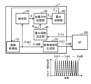
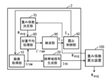
- FIG. 1 is a diagram illustrating an example of a schematic configuration of an imaging device according to a first embodiment of the present disclosure.
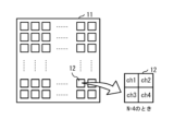
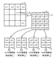
- 2 is a diagram illustrating an example of a schematic configuration of an image acquisition section in FIG. 1.
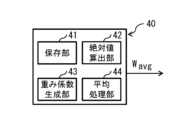
- FIG. 2 is a diagram illustrating an example of a schematic configuration of a weighting factor determining section in FIG. 1.
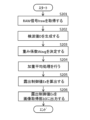
- FIG. 4 is a diagram illustrating an example of a method for deriving weighting coefficients in the weighting coefficient determining section of FIG. 3;
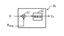
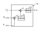
- 2 is a diagram illustrating an example of a schematic configuration of an evaluation value calculation section in FIG. 1.
- FIG. 2 is a diagram illustrating an example of AE control in the imaging device of FIG. 1.
- FIG. 2 is a diagram showing an example of spectral sensitivity characteristics of the image acquisition section in FIG. 1;
- FIG. 2 is a diagram illustrating a modified example of the schematic configuration of the weighting factor determining section in FIG. 1;
- FIG. 9 is a diagram illustrating an example of a method for deriving weighting coefficients in the weighting coefficient determining section of FIG. 8;
- 2 is a diagram illustrating a modified example of the schematic configuration of the imaging device in FIG. 1.
- FIG. 11 is a diagram illustrating an example of a schematic configuration of the weighting coefficient calculation device of FIG. 10.
- FIG. 11 is a diagram illustrating an example of a method for deriving weighting coefficients in the weighting coefficient calculation device of FIG. 10.
- FIG. 10 is a diagram showing an example of spectral sensitivity characteristics of the image acquisition section in FIG. 1;
- FIG. 2 is a diagram illustrating a modified example of the schematic configuration of the weighting factor determining section in FIG. 1;
- FIG. 9 is
- FIG. 2 is a diagram illustrating a modified example of the schematic configuration of the imaging device in FIG. 1.
- FIG. FIG. 14 is a diagram for explaining a method of deriving a detected value in the detection section of FIG. 13;
- FIG. 14 is a diagram illustrating an example of a schematic configuration of an evaluation value calculation unit in FIG. 13;
- 2 is a diagram illustrating a modified example of the schematic configuration of the imaging device in FIG. 1.
- FIG. 11 is a diagram illustrating a modified example of the schematic configuration of the imaging device in FIG. 10.
- FIG. 14 is a diagram illustrating a modified example of the schematic configuration of the imaging device in FIG. 13.
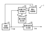
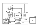
- FIG. FIG. 2 is a diagram illustrating an example of a schematic configuration of an imaging device according to a second embodiment of the present disclosure.
- FIG. 20 is a diagram illustrating an example of a schematic configuration of a weighted average processing section in FIG. 19.
- FIG. 20 is a diagram illustrating an example of AE control in the imaging device of FIG. 19.
- FIG. 20 is a diagram illustrating a modified example of the schematic configuration of the imaging device in FIG. 19.
- FIG. 20 is a diagram illustrating a modified example of the schematic configuration of the imaging device in FIG. 19.
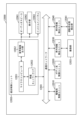
- FIG. 1 is a block diagram showing an example of a schematic configuration of a vehicle control system.
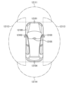
- FIG. 2 is an explanatory diagram showing an example of installation positions of an outside-vehicle information detection section and an imaging section.
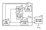
- FIG. 1 shows a schematic configuration example of an imaging device 1 according to a first embodiment of the present disclosure.
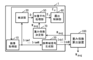
- the imaging device 1 includes an image acquisition section 10, a narrowband signal generation section 20, a detection section 30, a weighting factor determination section 40, a weighted average processing section 50, and an exposure control section 60.
- the image acquisition unit 10 corresponds to a specific example of the “multispectral sensor unit” of the present disclosure.
- the narrowband signal generation section 20 corresponds to a specific example of the "narrowband signal generation section” of the present disclosure.
- a module including the detection section 30, the weighted average processing section 50, and the exposure control section 60 corresponds to a specific example of the "control section" of the present disclosure.
- the weighting coefficient determining unit 40 corresponds to a specific example of the “weighting coefficient determining unit” of the present disclosure.
- the image acquisition section 10 includes, for example, a pixel array section 11, as shown in FIG. 2.
- the pixel array section 11 has a plurality of pixels 12 arranged two-dimensionally, and each pixel 12 outputs a pixel signal corresponding to the incident light that has entered through the aperture and the photographing lens.
- Each pixel 12 includes a photoelectric conversion element such as a photodiode.
- the pixel array section 11 is a multispectral sensor that outputs a plurality of (N) wavelength signals as pixel signals.
- the multispectral sensor is, for example, a solid-state imaging device such as a CCD (Charge Coupled Device) or a CMOS (Complementary Metal Oxide Semiconductor).
- Multispectral sensors provide multiple wavelength signals such as R (red), G (green), B (blue), Y (yellow), M (magenta), C (cyan), UV (ultraviolet), and NIR. Outputs signals in four or more wavelength bands (near infrared).
- the image acquisition unit 10 performs A/D conversion on pixel signals from the multispectral sensor, and outputs a RAW signal I raw based on the pixel signals.
- the image acquisition unit 10 sets exposure based on the exposure control value Ex input from the exposure control unit 60.
- the image acquisition unit 10 sets, for example, at least one of shutter speed, gain, and aperture based on the exposure control value Ex.
- the RAW signal I raw includes a plurality of (N) wavelength signals for each pixel 12.
- FIG. 1 illustrates a case where the RAW signal I raw is composed of N channel RAW signals I raw1 , . . . , I rawN .
- FIG. 2 exemplifies the configuration of subpixels included in each pixel 12 when the number of channels N is four.
- "ch1", “ch2”, “ch3”, and "ch4" represent that each pixel 12 includes four channels. Note that the pixel configuration in the pixel array section 11 is not limited to the above.
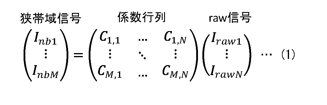
- the narrowband signal generation unit 20 generates a narrowband wavelength signal (narrowband A signal I nb ) is generated.
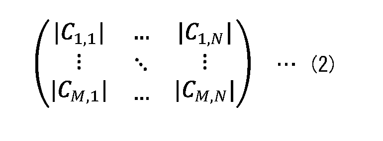
- the narrowband signal generation unit 20 uses the coefficient matrix described in equation (2) to generate a plurality of RAW signals I raw1 ,..., I rawk ,..., I rawN (1 ⁇ k ⁇ ) output from the image acquisition unit 10. N), a plurality of (M) narrowband signals I nb1 , ..., I nbt , ..., I nbM (1 ⁇ t ⁇ M) that are narrower than the wavelength signal output from the image acquisition unit 10 are generated.
- FIG. 1 exemplifies a case where the narrowband signal I nb is composed of M channel narrowband signals I nb1 , . . . , I nbM , which are larger than N channels.
- the detection unit 30 includes a detection circuit that generates a plurality of detection values (detection value D) based on a plurality of wavelength signals (RAW signal I raw ).
- the detected value D is composed of N channel detected values D 1 , D 2 , . . . , D k , . . . , DN , as shown in equation (3).
- the detected values D 1 , ..., D N correspond to the RAW signals I raw1 , ..., I rawN for each channel k.
- the detection circuit generates N-channel detection values D 1 , ..., D N based on the N-channel RAW signals I raw1 , ..., I rawN acquired from the image acquisition section 10 .
- the detection circuit generates a detection value D k based on the RAW signal I rawk .
- the detection section 30 outputs the detection value D generated by the detection circuit to the weighted average processing section 50.
- the weighting factor determining unit 40 determines a weighting factor W avg (Equation (4)) corresponding to the detected value D.
- the weighting coefficient W avg is composed of N-channel weighting coefficients w 1 avg , w 2 avg , ..., w k avg , ..., w N avg , as shown in equation (4).
- the weighting factor determination unit 40 assigns a plurality of weighting factors w 1 avg , w 2 avg , ..., w k avg , ... one to each detected value D 1 , D 2 , ..., D k , ..., D N , w N avg .
- the weighting factor determining unit 40 determines a weighting factor w k avg corresponding to the detected value D k .
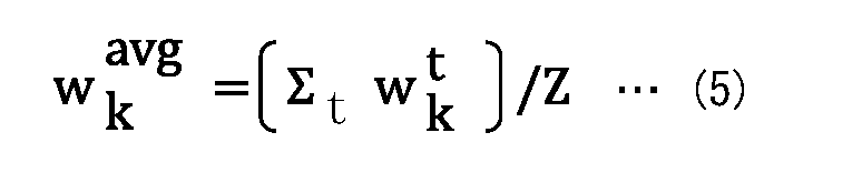
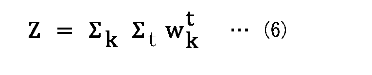
- the weighting factor determining unit 40 derives the weighting factor w k avg using equations (5) and (6).
- the weighting coefficient w k t for channel k is one element of the weighting coefficient list W_list , as shown in equations (7) and (8).
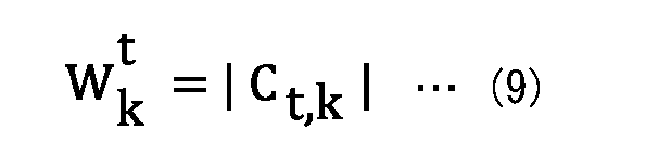
- the weighting coefficient w k t is the absolute value of one element included in the coefficient matrix described in equation (2). Therefore, the weighting coefficient list W_list is configured by the absolute value of each element included in the coefficient matrix described in equation (2).
- the weighting coefficient determining unit 40 determines the weighting coefficients W avg (weighting coefficients of N channels w 1 avg , w 2 avg , ..., w k avg , ... , w N avg ).
- the weighting coefficient determining unit 40 includes, for example, as shown in FIG. 3, a storage unit 41, an absolute value calculation unit 42, a weighting coefficient generation unit 43, and an average processing unit 44.
- the storage unit 41 is configured by, for example, non-volatile memory (NVM).
- the storage unit 41 stores the coefficient matrix described in equation (2).
- the absolute value calculation unit 42 acquires the coefficient matrix from the storage unit 41 (step S101, FIG. 4).
- the absolute value calculation unit 42 calculates the absolute value of each element of the coefficient matrix acquired from the storage unit 41 using equation (9) (step S102, FIG. 4).
- the weighting coefficient generation unit 43 generates the weighting coefficient list W_list shown in equation (7) using the calculated absolute value (step S102, FIG. 4).
- the average processing unit 44 calculates the average value (weighting coefficient W avg ) of the weighting coefficient list W _list using equations (4) to (6).
- the average processing unit 44 calculates a weighting coefficient W k avg for each channel k.
- the average processing section 44 outputs the calculated weighting coefficient W avg to the weighted average processing section 50 .
- the weighted average processing unit 50 calculates the evaluation value Ev by performing weighted average processing on the detected values D (detected values D 1 , D 2 , . . . , D k , . . . , D N of N channels).
- the weighted average processing unit 50 performs weighted average processing based on the weighting coefficient W avg determined by the weighting coefficient determining unit 40 .
- the weighted average processing unit 50 performs weighted average processing based on each element included in the coefficient matrix.
- the weighted average processing section 50 includes, for example, a multiplication section 51 and an integration section 52, as shown in FIG.
- the multiplication unit 51 multiplies the detected value D k and the weighting coefficient w k avg for each channel k, and outputs the resulting value (D k ⁇ w k avg ) to the integration unit 52 .
- the integration unit 52 integrates the value (D k ⁇ w k avg ) input from the multiplication unit 51 over all channels, and outputs the evaluation value Ev obtained thereby to the exposure control unit 60 .
- the exposure control unit 60 calculates an exposure control value Ex based on the evaluation value Ev input from the weighted average processing unit 50. For example, the exposure control unit 60 calculates an exposure value (time) by dividing the exposure target value by the evaluation value Ev, and calculates the exposure control value Ex based on the calculated exposure value (time). The exposure control section 60 outputs the calculated exposure control value Ex to the image acquisition section 10. In this way, the exposure control section 60 performs exposure control (AE control) of the image acquisition section 10 (multispectral sensor) based on the evaluation value Ev.
- AE control exposure control
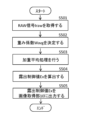
- FIG. 6 shows an example of AE control in the imaging device 1.
- the image acquisition unit 10 sets the exposure based on the initial value of the exposure control value Ex, and then performs imaging. Thereby, the image acquisition unit 10 acquires the RAW signal I raw based on the initial value of the exposure control value Ex (step S201).
- the detection unit 30 generates a detection value D based on the RAW signal I raw (step S202).
- the weighting factor determining unit 40 determines a weighting factor W avg corresponding to the detected value D (step S203).
- the weighted average processing unit 50 performs weighted average processing on the detected value D (step S204). Thereby, the weighted average processing unit 50 obtains the evaluation value Ev.
- the exposure control unit 60 calculates an exposure control value Ex based on the evaluation value Ev (step S205).
- the exposure control section 60 outputs the calculated exposure control value Ex to the image acquisition section 10.
- the image acquisition unit 10 can perform imaging after setting the exposure based on the input new exposure control value Ex.
- Imaging devices capable of performing multispectral imaging have been developed (for example, see Patent Documents 1 to 3).
- multispectral imaging multispectral images using more wavelength bands can be captured in one shot compared to imaging with an RGB sensor that uses red (R), green (G), and blue (B) as imaging wavelengths. It is possible to obtain it.
- RGB red
- G green
- B blue
- a single wavelength band is used for AE control.
- exposure control using only a single wavelength band it is difficult to properly expose a desired subject, for example, when capturing an image that includes a plurality of subjects with large differences in illuminance.
- the evaluation value Ev is calculated by performing weighted average processing on the detection value D generated using a plurality of wavelength signals as pixel signals output from the image acquisition unit 10. . Exposure control of the image acquisition unit 10 is then performed based on the calculated evaluation value Ev. In this way, by performing weighted average processing on the detection value D, it is possible to decide which channel of the image acquisition unit 10 is to be given importance. As a result, it is possible to effectively suppress deterioration (overexposure or underexposure of the image) in the output narrowband signal Inb . Therefore, in this embodiment, it is possible to perform appropriate exposure so as to suppress blown-out highlights or blown-out shadows in the image.
- weighted average processing is performed based on each element included in the coefficient matrix.
- weighted average processing is performed based on the weighting coefficient W avg determined by the weighting coefficient determination unit 40.
- the weighting coefficient W avg is determined based on each element included in the coefficient matrix. Therefore, it is possible to decide which channel of the image acquisition unit 10 is to be given importance. As a result, it is possible to effectively suppress deterioration (overexposure or underexposure of the image) in the output narrowband signal Inb . Therefore, in this embodiment, it is possible to perform appropriate exposure so as to suppress blown-out highlights or blown-out shadows in the image.
- the weighting coefficient determination unit 40 may determine the weighting coefficient W avg based on the spectral sensitivity characteristics of the image acquisition unit 10 (multispectral sensor).
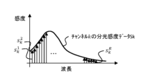
- the weighted average processing unit 50 can perform weighted average processing based on the spectral sensitivity characteristics (spectral sensitivity data S k ) for each channel k as shown in FIG. 7, for example.
- the spectral sensitivity data S k of channel k is data quantized into R pieces, as shown in equation (10). Furthermore, the spectral sensitivity data S' k corresponding to each band of the narrowband signal I nb extracted from the spectral sensitivity data S k of channel k are expressed as S' k 1 , S ' k 2 ,..., S' k t ,..., S' k M. In this modification, the weighting coefficient w k t for channel k is S' k t , as shown in equation (12).
- the weighting coefficient list W_list is composed of spectral sensitivity data S' k t corresponding to each band of the narrowband signal I nb extracted from the spectral sensitivity data S k of each channel k.
- the weighting coefficient determination unit 40 determines the weighting coefficient W avg ( weight of N channels The coefficients w 1 avg , w 2 avg , ..., w k avg , ..., w N avg ) are determined.
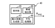
- the weighting coefficient determining unit 40 includes, for example, a storage unit 45, a band extraction unit 46, a weighting coefficient generation unit 47, and an average processing unit 48, as shown in FIG.
- the storage unit 45 is made up of, for example, a nonvolatile memory.
- spectral sensitivity data S k described in equation (10) is stored for each channel k.
- the band extraction unit 46 acquires the spectral sensitivity data Sk from the storage unit 45 (step S301, FIG. 9).
- the band extractor 46 extracts spectral sensitivity data S'k corresponding to each band of the narrowband signal Inb from the spectral sensitivity data Sk acquired from the storage unit 45 (step S302, FIG. 9).
- the weighting coefficient generation unit 47 generates a weighting coefficient list W_list using the extracted spectral sensitivity data S'k (step S303, FIG. 9).
- the average processing unit 48 calculates the average value (weighting coefficient W avg ) of the weighting coefficient list W _list using equations (4) to (6) (step S304, FIG. 9).
- the average processing unit 48 calculates a weighting coefficient W k avg for each channel k.
- the average processing section 48 outputs the calculated weighting coefficient W avg to the weighted average processing section 50 .
- weighted average processing is performed based on the spectral sensitivity characteristics (spectral sensitivity data S k ) for each channel k.
- the weighting coefficient W avg is determined based on the spectral sensitivity characteristics (spectral sensitivity data S k ) for each channel k.
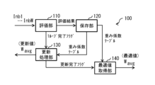
- the weighting coefficient calculation device 100 calculates weights suitable for the input narrow band signals I nb1 , ..., I nbt , ..., I nbM . It is configured to include a learning model trained to output the coefficient W avg .
- the weighting coefficient calculation device 100 includes, for example, an evaluation section 110, a storage section 120, an update processing section 130, and an optimum value acquisition section 140, as shown in FIG.
- the storage unit 120 stores the initial value of the weighting coefficient W avg .
- the update processing unit 130 first reads the initial value of the weighting coefficient W avg from the storage unit 120 and outputs it to the imaging device 1 (step S401, FIG. 12).
- the imaging device 1 calculates an exposure control value Ex using the weighting coefficient W avg input from the weighting coefficient calculation device 100, and sets exposure based on the calculated exposure control value Ex.
- the imaging device 1 performs imaging after setting the exposure based on the exposure control value Ex. As a result, the imaging device 1 outputs the narrowband signal I nb based on the initial value of the weighting coefficient W avg .
- the evaluation unit 110 acquires the narrowband signal Inb from the imaging device 1 (step S402, FIG. 12). When the evaluation unit 110 acquires the narrowband signal I nb from the narrowband signal generation unit 20, it evaluates the acquired narrowband signal I nb (step S403, FIG. 12). The evaluation unit 110 generates a new weighting coefficient W avg based on the evaluation result of the acquired narrowband signal I nb (step S404, FIG. 12). The evaluation unit 110 stores the evaluation result and the weighting coefficient W avg in the storage unit 120 in association with each other. The evaluation unit 110 outputs a flag indicating completion of the evaluation (1 loop completion flag) to the update processing unit 130.
- the update processing unit 130 When the update processing unit 130 obtains a flag indicating completion of evaluation (one loop completion flag) from the evaluation unit 110, the update processing unit 130 reads the evaluation result and the weighting coefficient W avg from the storage unit 120, and applies the new weighting coefficient W avg to the imaging device 1. (Step S405, FIG. 12).
- the evaluation section 110, the storage section 120, and the update processing section 130 execute the above processing every time the narrowband signal Inb is input from the narrowband signal generation section 20.
- the update processing unit 130 When the value of the weighting coefficient W avg converges, the update processing unit 130 generates a flag indicating convergence (update completion flag) and outputs it to the optimum value acquisition unit 140 .
- the optimal value acquisition unit 140 receives the flag from the update processing unit 130, it reads the weighting coefficient W avg from the storage unit 120 and outputs the read weighting coefficient W avg to the outside.
- the value generated by the learning model in the weighting factor calculation device 100 is determined as the weighting factor W avg .
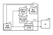
- the weighting coefficient determination unit 40 uses each element included in the coefficient matrix and the specification information input from the application device 200 connected to the imaging device 1, as shown in FIG. 13, for example.
- the weighting coefficient W avg may be determined based on this.
- the weighted average processing unit 50 can perform weighted average processing based on each element included in the coefficient matrix and the designation information input from the application device 200 connected to the imaging device 1.
- the above-mentioned "designation information” is information that designates at least one band among the plurality of bands included in the narrowband signal Inb .
- two bands specified by the above-mentioned “designation information” are illustrated by thick solid lines.
- the narrowband signal generation unit 20 may output M narrowband signals I nb1 , ..., I nbt , ..., I nbM as the narrowband signal I nb to the application device 200, and may also output the M narrowband signals I nb1 , ..., I nbt , ..., I nbM to the application device 200, and may output the M narrowband signals I nb1 , ..., I nbt , ..., I nbM to the application device 200, and may also output the M narrowband signals I nb1 , ..., I nbt , ..., I nbM to the application device 200 .
- Only one or more narrowband signals Inbt specified by Inbt may be output to the application device 200.
- the narrowband signal generation unit 20 outputs only one or more narrowband signals Inbt specified by the above-mentioned "designation information" to the application device 200, the amount of data transmitted from the imaging device 1 to the application device 200 is kept low. be able to.
- the weighting coefficient determining unit 40 determines the weighting coefficient for each divided area ⁇ j (FIG. 14) that divides the pixel area of the pixel array unit 11, for example. W avg may also be determined. At this time, in the divided area ⁇ j, a plurality of pixels 12 are allocated to each channel k.
- the detection unit 30 classifies the plurality of pixel signals output from the pixel array unit 11 (multispectral sensor) for each partitioned area ⁇ j, and integrates the plurality of pixel signals for each channel k for each partitioned area ⁇ j. Thereby, the detection circuit can generate a detection value D k j for each channel k and for each partitioned area ⁇ j, as shown in equations (3) and (13).
- the weighted average processing unit 50 calculates the evaluation value Ev by performing weighted average processing on the detected values D k j generated for each channel k and each divided area ⁇ j.
- the weighted average processing section 50 includes, for example, multiplication sections 51 and 53, an integration section 52, and a normalization section 54, as shown in FIG.
- the multiplier 53 multiplies the weighting coefficient W k_avg for each channel k and the weighting coefficient W j_avg for each divided area ⁇ j.
- the normalization unit 54 normalizes the value (W k_avg ⁇ W j_avg ) obtained by the multiplication unit 53. Let w k avg be the value obtained by normalization in the normalization unit 54 .
- the multiplication unit 51 multiplies the detected value D k and the value w k avg obtained by normalization in the normalization unit 54 for each channel, and the obtained value (D k ⁇ w k avg ) is output to the integration section 52.
- the integration unit 52 integrates the value (D k ⁇ w k avg ) input from the multiplication unit 51 over all channels, and outputs the evaluation value Ev obtained thereby to the exposure control unit 60 .
- the detection unit 30 may generate a number Q of detected values different from the number N of channels. .
- the weighting coefficient determination unit 40 determines Q weighting coefficients corresponding to the Q detected values. Even in this case, it is possible to obtain the same effects as in the above-described embodiment and modifications 1-1, 1-2, 1-3, and 1-4.
- the detection section 30 may be omitted.
- the detection section 30 is omitted, and instead of the detection value D, the output of the image acquisition section 10 (RAW signal I raw ) is input to the weighted average processing section 50. may be done.
- the weighting factor determination unit 40 determines the weighting factor W avg (Equation (4)) corresponding to the RAW signal I raw .
- the weighting factor determining unit 40 assigns a plurality of weighting factors w 1 avg , w 2 avg , ..., w k avg , ..., w N that are assigned one to each RAW signal I raw1 , ..., I rawk , ..., I rawN . Determine avg .
- the weighting factor determining unit 40 determines a weighting factor w k avg corresponding to the RAW signal w k avg .
- the weighted average processing unit 50 calculates the evaluation value Ev by performing weighted average processing on the RAW signal I raw .
- the weighted average processing unit 50 performs weighted average processing based on the weighting coefficient W avg determined by the weighting coefficient determining unit 40 . Even in this case, it is possible to obtain the same effects as in the above-described embodiment and modifications 1-1, 1-2, 1-3, and 1-4.
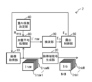
- FIG. 19 shows a schematic configuration example of an imaging device 2 according to a second embodiment of the present disclosure.
- the imaging device 2 includes an image acquisition section 10, a narrowband signal generation section 20, a weighting factor determination section 40, a weighted average processing section 80, a detection section 90, and an exposure control section 60.
- the image acquisition unit 10 corresponds to a specific example of the “multispectral sensor unit” of the present disclosure.
- the narrowband signal generation section 20 corresponds to a specific example of the "narrowband signal generation section” of the present disclosure.
- a module including the weighted average processing section 80, the detection section 90, and the exposure control section 60 corresponds to a specific example of the "control section" of the present disclosure.
- the weighting coefficient determining unit 40 corresponds to a specific example of the “weighting coefficient determining unit” of the present disclosure.
- the weighted average processing unit 80 calculates the RAW signal I′ raw by performing weighted average processing on the RAW signal I raw (N channel RAW signals I raw1 , . . . , I rawN ).
- the weighted average processing unit 80 performs weighted average processing based on each element included in the coefficient matrix.
- the weighted average processing section 80 includes, for example, a multiplication section 81 and an integration section 82, as shown in FIG.
- the multiplier 81 multiplies the RAW signal I rawk and the weighting coefficient w k avg for each channel k, and outputs the resulting value (I rawk ⁇ w k avg ) to the integrating unit 82 .
- the integrating unit 82 integrates the value (I rawk ⁇ w k avg ) input from the multiplying unit 81 over all channels, and uses the resulting value as the RAW signal I' raw for one channel to the detecting unit. Output to 90.
- the detection section 90 has a detection circuit that generates p detection values (p ⁇ 1) based on the RAW signal I' raw .
- the detection unit 90 calculates an evaluation value Ev based on the p detection values generated by the detection circuit.
- the evaluation value calculation unit 83 outputs the calculated evaluation value Ev to the exposure control unit 60.
- FIG. 21 shows an example of AE control in the imaging device 2.
- the image acquisition unit 10 sets the exposure based on the initial value of the exposure control value Ex, and then performs imaging. Thereby, the image acquisition unit 10 acquires the RAW signal I raw based on the initial value of the exposure control value Ex (step S501).
- the weighting coefficient determination unit 40 determines the weighting coefficient W avg corresponding to each channel k (step S502).
- the weighted average processing unit 80 performs weighted average processing on the N-channel RAW signal I rawk (step S503). Thereby, the weighted average processing section 80 obtains the RAW signal I' raw for one channel.
- the detection unit 90 generates a detection value D for one channel based on the RAW signal I' raw , and calculates an evaluation value Ev based on the generated detection value D.
- the exposure control unit 60 calculates an exposure control value Ex based on the evaluation value Ev (step S504).
- the exposure control section 60 outputs the calculated exposure control value Ex to the image acquisition section 10.
- the image acquisition unit 10 can perform imaging after setting the exposure based on the input new exposure control value Ex.
- the RAW signal I' raw is calculated by performing weighted average processing on the RAW signal I raw obtained from the image acquisition unit 10, and the evaluation is performed based on the calculated RAW signal I' raw .
- a value Ev is calculated.
- Exposure control of the image acquisition unit 10 is then performed based on the calculated evaluation value Ev.
- the weighting coefficient determination unit 40 may determine the weighting coefficient W avg based on the spectral sensitivity characteristics of the image acquisition unit 10 (multispectral sensor). At this time, the evaluation value calculation unit 50 can perform weighted average processing based on the spectral sensitivity characteristics (spectral sensitivity data S k ) for each channel k as shown in FIG. 7, for example.
- the weighting factor determining section 40 includes, for example, as shown in FIG. 8, a storage section 45, a band extraction section 46, a weighting factor generation section 47, and an averaging section 48.
- weighted average processing is performed based on the spectral sensitivity characteristics (spectral sensitivity data S k ) for each channel k.
- the weighting coefficient W avg is determined based on the spectral sensitivity characteristics (spectral sensitivity data S k ) for each channel k.
- a weighting coefficient determination unit 70 may be provided that determines the weighting coefficient as follows.
- the value generated by the learning model in the weighting factor calculation device 100 is determined as the weighting factor W avg .
- the weighting coefficient determination unit 40 for example, as shown in FIG.
- the weighting coefficient W avg may be determined based on the information.
- the weighted average processing unit 80 can perform weighted average processing based on each element included in the coefficient matrix and the designation information input from the application device 200 connected to the imaging device 2.
- the above-mentioned "designation information” is information that designates at least one band among the plurality of bands included in the narrowband signal Inb .
- the imaging device 2 determines a weighting coefficient W avg that can suppress deterioration in a band in which deterioration (overexposure or overshadowing of an image) is particularly desired to be suppressed. can be generated. As a result, it is possible to effectively suppress deterioration (blown-out highlights or blocked-up shadows in an image) in a specific band.
- the exposure control unit 60 receives the evaluation value Ev input from the weighted average processing unit 50 and the application device connected to the imaging device 1.
- the exposure control value Ex may be calculated based on the information.
- the application device is a device that performs processing using the plurality of narrowband signals Inb output from the imaging device 1.
- Information input from the application device may include, for example, the maximum exposure time determined based on system hardware constraints or the maximum gain determined based on sensor usage.
- the exposure control value Ex By calculating the exposure control value Ex based on such known information, for example, if the score is low in a scene where blur is likely to occur, the exposure time may be shortened, or if the score is low in a scene where noise is likely to occur. You can reduce the gain to
- examples of information input from the application device include evaluation values.
- Examples of the evaluation value include recognition processing results and S/N results.
- the results of the recognition process include, for example, information regarding whether a specific object has been detected, the class of the detected object, or a setting value according to the velocity vector of the moving object.
- the technology according to the present disclosure (this technology) can be applied to various products.
- the technology according to the present disclosure may be realized as a device mounted on any type of moving body such as a car, electric vehicle, hybrid electric vehicle, motorcycle, bicycle, personal mobility, airplane, drone, ship, robot, etc. It's okay.
- FIG. 24 is a block diagram illustrating a schematic configuration example of a vehicle control system, which is an example of a mobile body control system to which the technology according to the present disclosure can be applied.
- the vehicle control system 12000 includes a plurality of electronic control units connected via a communication network 12001.
- the vehicle control system 12000 includes a drive system control unit 12010, a body system control unit 12020, an outside vehicle information detection unit 12030, an inside vehicle information detection unit 12040, and an integrated control unit 12050.
- a microcomputer 12051, an audio/image output section 12052, and an in-vehicle network I/F (Interface) 12053 are illustrated as the functional configuration of the integrated control unit 12050.
- the drive system control unit 12010 controls the operation of devices related to the drive system of the vehicle according to various programs.
- the drive system control unit 12010 includes a drive force generation device such as an internal combustion engine or a drive motor that generates drive force for the vehicle, a drive force transmission mechanism that transmits the drive force to wheels, and a drive force transmission mechanism that controls the steering angle of the vehicle. It functions as a control device for a steering mechanism to adjust and a braking device to generate braking force for the vehicle.
- the body system control unit 12020 controls the operations of various devices installed in the vehicle body according to various programs.
- the body system control unit 12020 functions as a keyless entry system, a smart key system, a power window device, or a control device for various lamps such as a headlamp, a back lamp, a brake lamp, a turn signal, or a fog lamp.
- radio waves transmitted from a portable device that replaces a key or signals from various switches may be input to the body control unit 12020.
- the body system control unit 12020 receives input of these radio waves or signals, and controls the door lock device, power window device, lamp, etc. of the vehicle.
- the external information detection unit 12030 detects information external to the vehicle in which the vehicle control system 12000 is mounted.
- an imaging section 12031 is connected to the outside-vehicle information detection unit 12030.
- the vehicle exterior information detection unit 12030 causes the imaging unit 12031 to capture an image of the exterior of the vehicle, and receives the captured image.
- the external information detection unit 12030 may perform object detection processing such as a person, car, obstacle, sign, or text on the road surface or distance detection processing based on the received image.
- the imaging unit 12031 is an optical sensor that receives light and outputs an electrical signal according to the amount of received light.
- the imaging unit 12031 can output the electrical signal as an image or as distance measurement information.
- the light received by the imaging unit 12031 may be visible light or non-visible light such as infrared rays.
- the in-vehicle information detection unit 12040 detects in-vehicle information.
- a driver condition detection section 12041 that detects the condition of the driver is connected to the in-vehicle information detection unit 12040.
- the driver condition detection unit 12041 includes, for example, a camera that images the driver, and the in-vehicle information detection unit 12040 detects the degree of fatigue or concentration of the driver based on the detection information input from the driver condition detection unit 12041. It may be calculated, or it may be determined whether the driver is falling asleep.
- the microcomputer 12051 calculates control target values for the driving force generation device, steering mechanism, or braking device based on the information inside and outside the vehicle acquired by the vehicle exterior information detection unit 12030 or the vehicle interior information detection unit 12040, Control commands can be output to 12010.
- the microcomputer 12051 realizes ADAS (Advanced Driver Assistance System) functions, including vehicle collision avoidance or impact mitigation, following distance based on vehicle distance, vehicle speed maintenance, vehicle collision warning, vehicle lane departure warning, etc. It is possible to perform cooperative control for the purpose of ADAS (Advanced Driver Assistance System) functions, including vehicle collision avoidance or impact mitigation, following distance based on vehicle distance, vehicle speed maintenance, vehicle collision warning, vehicle lane departure warning, etc. It is possible to perform cooperative control for the purpose of
- ADAS Advanced Driver Assistance System
- the microcomputer 12051 controls the driving force generating device, steering mechanism, braking device, etc. based on information about the surroundings of the vehicle acquired by the vehicle exterior information detection unit 12030 or the vehicle interior information detection unit 12040. It is possible to perform cooperative control for the purpose of autonomous driving, etc., which does not rely on operation.
- the microcomputer 12051 can output a control command to the body system control unit 12020 based on the information outside the vehicle acquired by the outside information detection unit 12030.
- the microcomputer 12051 controls the headlamps according to the position of the preceding vehicle or oncoming vehicle detected by the vehicle exterior information detection unit 12030, and performs cooperative control for the purpose of preventing glare, such as switching from high beam to low beam. It can be carried out.
- the audio and image output unit 12052 transmits an output signal of at least one of audio and images to an output device that can visually or audibly notify information to the occupants of the vehicle or to the outside of the vehicle.
- an audio speaker 12061, a display section 12062, and an instrument panel 12063 are illustrated as output devices.
- the display unit 12062 may include, for example, at least one of an on-board display and a head-up display.
- FIG. 25 is a diagram showing an example of the installation position of the imaging section 12031.
- the imaging unit 12031 includes imaging units 12101, 12102, 12103, 12104, and 12105.
- the imaging units 12101, 12102, 12103, 12104, and 12105 are provided at, for example, the front nose of the vehicle 12100, the side mirrors, the rear bumper, the back door, and the upper part of the windshield inside the vehicle.
- An imaging unit 12101 provided in the front nose and an imaging unit 12105 provided above the windshield inside the vehicle mainly acquire images in front of the vehicle 12100.
- Imaging units 12102 and 12103 provided in the side mirrors mainly capture images of the sides of the vehicle 12100.
- An imaging unit 12104 provided in the rear bumper or back door mainly captures images of the rear of the vehicle 12100.
- the imaging unit 12105 provided above the windshield inside the vehicle is mainly used to detect preceding vehicles, pedestrians, obstacles, traffic lights, traffic signs, lanes, and the like.
- FIG. 25 shows an example of the imaging range of the imaging units 12101 to 12104.
- An imaging range 12111 indicates the imaging range of the imaging unit 12101 provided on the front nose
- imaging ranges 12112 and 12113 indicate imaging ranges of the imaging units 12102 and 12103 provided on the side mirrors, respectively
- an imaging range 12114 shows the imaging range of the imaging unit 12101 provided on the front nose.
- the imaging range of the imaging unit 12104 provided in the rear bumper or back door is shown. For example, by overlapping the image data captured by the imaging units 12101 to 12104, an overhead image of the vehicle 12100 viewed from above can be obtained.
- At least one of the imaging units 12101 to 12104 may have a function of acquiring distance information.
- at least one of the imaging units 12101 to 12104 may be a stereo camera including a plurality of image sensors, or may be an image sensor having pixels for phase difference detection.
- the microcomputer 12051 determines the distance to each three-dimensional object within the imaging ranges 12111 to 12114 and the temporal change in this distance (relative speed with respect to the vehicle 12100) based on the distance information obtained from the imaging units 12101 to 12104. By determining the following, it is possible to extract, in particular, the closest three-dimensional object on the path of vehicle 12100, which is traveling at a predetermined speed (for example, 0 km/h or more) in approximately the same direction as vehicle 12100, as the preceding vehicle. can. Furthermore, the microcomputer 12051 can set an inter-vehicle distance to be secured in advance in front of the preceding vehicle, and perform automatic brake control (including follow-up stop control), automatic acceleration control (including follow-up start control), and the like. In this way, it is possible to perform cooperative control for the purpose of autonomous driving, etc., in which the vehicle travels autonomously without depending on the driver's operation.
- automatic brake control including follow-up stop control
- automatic acceleration control including follow-up start control
- the microcomputer 12051 transfers three-dimensional object data to other three-dimensional objects such as two-wheeled vehicles, regular vehicles, large vehicles, pedestrians, and utility poles based on the distance information obtained from the imaging units 12101 to 12104. It can be classified and extracted and used for automatic obstacle avoidance. For example, the microcomputer 12051 identifies obstacles around the vehicle 12100 into obstacles that are visible to the driver of the vehicle 12100 and obstacles that are difficult to see. Then, the microcomputer 12051 determines a collision risk indicating the degree of risk of collision with each obstacle, and when the collision risk exceeds a set value and there is a possibility of a collision, the microcomputer 12051 transmits information via the audio speaker 12061 and the display unit 12062. By outputting a warning to the driver via the vehicle control unit 12010 and performing forced deceleration and avoidance steering via the drive system control unit 12010, driving support for collision avoidance can be provided.
- the microcomputer 12051 determines a collision risk indicating the degree of risk of collision with each obstacle, and when the collision risk exceed
- At least one of the imaging units 12101 to 12104 may be an infrared camera that detects infrared rays.
- the microcomputer 12051 can recognize a pedestrian by determining whether the pedestrian is present in the images captured by the imaging units 12101 to 12104.
- pedestrian recognition involves, for example, a procedure for extracting feature points in images captured by the imaging units 12101 to 12104 as infrared cameras, and a pattern matching process is performed on a series of feature points indicating the outline of an object to determine whether it is a pedestrian or not.
- the audio image output unit 12052 creates a rectangular outline for emphasis on the recognized pedestrian.
- the display unit 12062 is controlled to display the .
- the audio image output unit 12052 may control the display unit 12062 to display an icon or the like indicating a pedestrian at a desired position.
- the technology according to the present disclosure can be applied to the imaging unit 12031 among the configurations described above.
- control using multispectral images can be performed.
- the present disclosure can take the following configuration. (1) a multispectral sensor unit that outputs a plurality of (N) wavelength signals as pixel signals; a narrowband signal generation unit that uses a coefficient matrix to generate a plurality of (M (M>N) narrowband signals narrower than the wavelength signals from the plurality of wavelength signals output from the multispectral sensor); and, An evaluation value is calculated by performing weighted average processing on the plurality of wavelength signals or a plurality of detection values generated using the plurality of wavelength signals, and the multispectral sensor is calculated based on the calculated evaluation value.
- An imaging device comprising: a control section for controlling exposure of the section; (2) The imaging device according to (1), wherein the control unit performs the weighted average processing based on each element included in the coefficient matrix. (3) The imaging device according to (1), wherein the control unit performs the weighted average processing based on spectral sensitivity characteristics of the multispectral sensor unit. (4) The imaging device according to (1) or (2), wherein the control unit performs the weighted average processing based on each element included in the coefficient matrix and designation information that designates the narrowband signal.
- (5) further comprising a weighting coefficient determination unit that determines a plurality of weighting coefficients to be assigned to each of the wavelength signals or to each of the detected values,
- the control unit performs the weighted average processing based on the plurality of weighting coefficients determined by the weighting coefficient determining unit.
- the weighting coefficient determination unit determines the plurality of weighting coefficients based on each element included in the coefficient matrix.
- the weighting coefficient determining unit determines the plurality of weighting coefficients based on spectral sensitivity characteristics of the multispectral sensor unit.
- the imaging device wherein the weighting coefficient determination unit determines the plurality of weighting coefficients based on each element included in the coefficient matrix and designation information that designates the narrowband signal.
- the weighting coefficient determination unit determines the plurality of weighting coefficients for each partitioned area that partitions a pixel area of the multispectral sensor unit.
- the control unit may classify each of the wavelength signals into divided areas that partition a pixel area of the multispectral sensor unit, and perform weighted average processing on the plurality of detected values generated for each divided area.
- the imaging device wherein the evaluation value is calculated by: (11)
- the control unit performs the exposure control based on the evaluation value and information obtained from a device that performs processing using the plurality of narrowband signals.
- the imaging device described in (12) Using a coefficient matrix, from a plurality of (N) wavelength signals as pixel signals output from a multispectral sensor, generate a plurality of (M (M>N) narrowband signals narrower than the wavelength signals) to do and
- An evaluation value is calculated by performing weighted average processing on the plurality of wavelength signals or a plurality of detection values generated using the plurality of wavelength signals, and the multispectral sensor is calculated based on the calculated evaluation value.
- a signal processing method comprising controlling the exposure of a portion of the image.
- a plurality of wavelength signals as pixel signals output from a multispectral sensor or a plurality of detected values generated using the plurality of wavelength signals are weighted.
- An evaluation value is calculated by performing averaging processing. Exposure control of the multispectral sensor section is then performed based on the calculated evaluation value.
Landscapes
- Engineering & Computer Science (AREA)
- Multimedia (AREA)
- Signal Processing (AREA)
- Physics & Mathematics (AREA)
- Spectroscopy & Molecular Physics (AREA)
- General Physics & Mathematics (AREA)
- Color Television Image Signal Generators (AREA)
- Studio Devices (AREA)
Abstract
Description
(A)係数行列を用いて、マルチスペクトルセンサから出力された画素信号としての複数(N個)の波長信号から、波長信号よりも狭帯域の複数(M個(M>N)の狭帯域信号を生成すること
(B)複数の波長信号、もしくは複数の波長信号を用いて生成された複数の検波値に対して加重平均処理を行うことにより評価値を算出し、算出した評価値に基づいてマルチスペクトルセンサ部の露出制御を行うこと
図1は、本開示の第1の実施の形態に係る撮像装置1の概略構成例を表したものである。撮像装置1は、例えば、図1に示したように、画像取得部10、狭帯域信号生成部20、検波部30、重み係数決定部40、加重平均処理部50および露出制御部60を備えている。画像取得部10が、本開示の「マルチスペクトルセンサ部」の一具体例に相当する。狭帯域信号生成部20が、本開示の「狭帯域信号生成部」の一具体例に相当する。検波部30、加重平均処理部50および露出制御部60からなるモジュールが、本開示の「制御部」の一具体例に相当する。重み係数決定部40が、本開示の「重み係数決定部」の一具体例に相当する。




次に、撮像装置1におけるAE制御について説明する。図6は、撮像装置1におけるAE制御の一例を表したものである。
次に、撮像装置1の効果について説明する。
[変形例1-1]
上記実施の形態において、重み係数決定部40は、画像取得部10(マルチスペクトルセンサ)の分光感度特性に基づいて重み係数Wavgを決定してもよい。このとき、加重平均処理部50は、例えば、図7に示したようなチャネルkごとの分光感度特性(分光感度データSk)に基づいて加重平均処理を行うことが可能である。



上記実施の形態において、重み係数決定部40の代わりに、例えば、図10に示したように、撮像装置1と連結された重み係数算出装置100から得られた値を重み係数Wavgとして決定する重み係数決定部70が設けられていてもよい。
上記実施の形態において、重み係数決定部40は、例えば、図13に示したように、係数行列に含まれる各要素と、撮像装置1と連結されたアプリケーション装置200から入力された指定情報とに基づいて重み係数Wavgを決定してもよい。このとき、加重平均処理部50は、係数行列に含まれる各要素と、撮像装置1と連結されたアプリケーション装置200から入力された指定情報とに基づいて加重平均処理を行うことが可能である。
上記実施の形態および変形例1-1,1-2,1-3において、重み係数決定部40は、例えば、画素アレイ部11の画素領域を区画する区画領域αj(図14)ごとに重み係数Wavgを決定してもよい。このとき、区画領域αjでは、チャンネルkごとに複数の画素12が割り当てられている。

上記実施の形態および変形例1-1,1-2,1-3,1-4において、検波部30は、チャンネル数Nとは異なる数Qの検波値を生成するようになっていてもよい。このとき、重み係数決定部40は、Q個の検波値に対応するQ個の重み係数を決定するようになっている。このようにした場合であっても、上記実施の形態および変形例1-1,1-2,1-3,1-4と同様の効果を得ることができる。
上記実施の形態および変形例1-1,1-2,1-3,1-4において、検波部30が省略されていてもよい。例えば、図16、図17、図18に示したように、検波部30が省略され、検波値Dの代わりに、画像取得部10の出力(RAW信号Iraw)が加重平均処理部50に入力されてもよい。このとき、重み係数決定部40は、RAW信号Irawに対応する重み係数Wavg(式(4))を決定する。重み係数決定部40は、RAW信号Iraw1,…,Irawk,…,IrawNごとに1つずつ割り当てられる複数の重み係数w1 avg,w2 avg,…,wk avg,…,wN avgを決定する。重み係数決定部40は、RAW信号wk avgに対応する重み係数wk avgを決定する。加重平均処理部50は、RAW信号Irawに対して加重平均処理を行うことにより評価値Evを算出する。加重平均処理部50は、重み係数決定部40によって決定された重み係数Wavgに基づいて加重平均処理を行う。このようにした場合であっても、上記実施の形態および変形例1-1,1-2,1-3,1-4と同様の効果を得ることができる。
図19は、本開示の第2の実施の形態に係る撮像装置2の概略構成例を表したものである。撮像装置2は、例えば、図19に示したように、画像取得部10、狭帯域信号生成部20、重み係数決定部40、加重平均処理部80、検波部90および露出制御部60を備えている。画像取得部10が、本開示の「マルチスペクトルセンサ部」の一具体例に相当する。狭帯域信号生成部20が、本開示の「狭帯域信号生成部」の一具体例に相当する。加重平均処理部80、検波部90および露出制御部60からなるモジュールが、本開示の「制御部」の一具体例に相当する。重み係数決定部40が、本開示の「重み係数決定部」の一具体例に相当する。
次に、撮像装置2におけるAE制御について説明する。図21は、撮像装置2におけるAE制御の一例を表したものである。
次に、撮像装置2の効果について説明する。
[変形例2-1]
上記第2の実施の形態において、重み係数決定部40は、画像取得部10(マルチスペクトルセンサ)の分光感度特性に基づいて重み係数Wavgを決定してもよい。このとき、評価値算出部50は、例えば、図7に示したようなチャネルkごとの分光感度特性(分光感度データSk)に基づいて加重平均処理を行うことが可能である。重み係数決定部40は、例えば、図8に示したように、保存部45、帯域抽出部46、重み係数生成部47および平均処理部48を有している。
上記第2の実施の形態において、重み係数決定部40の代わりに、例えば、図22に示したように、撮像装置2と連結された重み係数算出装置100から得られた値を重み係数Wavgとして決定する重み係数決定部70が設けられていてもよい。
上記第2の実施の形態において、重み係数決定部40は、例えば、図23に示したように、係数行列に含まれる各要素と、撮像装置2と連結されたアプリケーション装置200から入力された指定情報とに基づいて重み係数Wavgを決定してもよい。このとき、加重平均処理部80は、係数行列に含まれる各要素と、撮像装置2と連結されたアプリケーション装置200から入力された指定情報とに基づいて加重平均処理を行うことが可能である。
上記第1および第2の実施の形態およびそれらの変形例において、露出制御部60は、加重平均処理部50から入力された評価値Evと、撮像装置1に接続されたアプリケーション装置から入力される情報とに基づいて、露出制御値Exを算出してもよい。アプリケーション装置は、撮像装置1から出力された複数の狭帯域信号Inbを利用した処理を行う装置である。
本開示に係る技術(本技術)は、様々な製品へ応用することができる。例えば、本開示に係る技術は、自動車、電気自動車、ハイブリッド電気自動車、自動二輪車、自転車、パーソナルモビリティ、飛行機、ドローン、船舶、ロボット等のいずれかの種類の移動体に搭載される装置として実現されてもよい。
(1)
画素信号として複数(N個)の波長信号を出力するマルチスペクトルセンサ部と、
係数行列を用いて、前記マルチスペクトルセンサから出力された前記複数の波長信号から、前記波長信号よりも狭帯域の複数(M個(M>N)の狭帯域信号を生成する狭帯域信号生成部と、
前記複数の波長信号、もしくは前記複数の波長信号を用いて生成された複数の検波値に対して加重平均処理を行うことにより評価値を算出し、算出した前記評価値に基づいて前記マルチスペクトルセンサ部の露出制御を行う制御部と
を備えた
撮像装置。
(2)
前記制御部は、前記係数行列に含まれる各要素に基づいて前記加重平均処理を行う
(1)に記載の撮像装置。
(3)
前記制御部は、前記マルチスペクトルセンサ部の分光感度特性に基づいて前記加重平均処理を行う
(1)に記載の撮像装置。
(4)
前記制御部は、前記係数行列に含まれる各要素と、前記狭帯域信号を指定する指定情報とに基づいて前記加重平均処理を行う
(1)または(2)に記載の撮像装置。
(5)
前記波長信号ごとに、もしくは前記検波値ごとに1つずつ割り当てられる複数の重み係数を決定する重み係数決定部を更に備え、
前記制御部は、前記重み係数決定部によって決定された前記複数の重み係数に基づいて前記加重平均処理を行う
(1)ないし(4)のいずれか1つに記載の撮像装置。
(6)
前記重み係数決定部は、前記係数行列に含まれる各要素に基づいて前記複数の重み係数を決定する
(5)に記載の撮像装置。
(7)
前記重み係数決定部は、前記マルチスペクトルセンサ部の分光感度特性に基づいて前記複数の重み係数を決定する
(5)に記載の撮像装置。
(8)
前記重み係数決定部は、前記係数行列に含まれる各要素と、前記狭帯域信号を指定する指定情報とに基づいて前記複数の重み係数を決定する
(5)に記載の撮像装置。
(9)
前記重み係数決定部は、前記マルチスペクトルセンサ部の画素領域を区画する区画領域ごとに前記複数の重み係数を決定する
(5)に記載の撮像装置。
(10)
前記制御部は、各前記波長信号を、前記マルチスペクトルセンサ部の画素領域を区画する区画領域ごとに分類し、前記区画領域ごとに生成した前記複数の検波値に対して加重平均処理を行うことにより前記評価値を算出する
(1)に記載の撮像装置。
(11)
前記制御部は、前記評価値と、前記複数の狭帯域信号を利用した処理を行う装置から得られた情報とに基づいて、前記露出制御を行う
(1)ないし(10)のいずれか1つに記載の撮像装置。
(12)
係数行列を用いて、マルチスペクトルセンサから出力された画素信号としての複数(N個)の波長信号から、前記波長信号よりも狭帯域の複数(M個(M>N)の狭帯域信号を生成することと、
前記複数の波長信号、もしくは前記複数の波長信号を用いて生成された複数の検波値に対して加重平均処理を行うことにより評価値を算出し、算出した前記評価値に基づいて前記マルチスペクトルセンサ部の露出制御を行うことと
を含む
信号処理方法。
Claims (12)
- 画素信号として複数(N個)の波長信号を出力するマルチスペクトルセンサ部と、
係数行列を用いて、前記マルチスペクトルセンサから出力された前記複数の波長信号から、前記波長信号よりも狭帯域の複数(M個(M>N)の狭帯域信号を生成する狭帯域信号生成部と、
前記複数の波長信号、もしくは前記複数の波長信号を用いて生成された複数の検波値に対して加重平均処理を行うことにより評価値を算出し、算出した前記評価値に基づいて前記マルチスペクトルセンサ部の露出制御を行う制御部と
を備えた
撮像装置。 - 前記制御部は、前記係数行列に含まれる各要素に基づいて前記加重平均処理を行う
請求項1に記載の撮像装置。 - 前記制御部は、前記マルチスペクトルセンサ部の分光感度特性に基づいて前記加重平均処理を行う
請求項1に記載の撮像装置。 - 前記制御部は、前記係数行列に含まれる各要素と、前記狭帯域信号を指定する指定情報とに基づいて前記加重平均処理を行う
請求項1に記載の撮像装置。 - 前記波長信号ごとに、もしくは前記検波値ごとに1つずつ割り当てられる複数の重み係数を決定する重み係数決定部を更に備え、
前記制御部は、前記重み係数決定部によって決定された前記複数の重み係数に基づいて前記加重平均処理を行う
請求項1に記載の撮像装置。 - 前記重み係数決定部は、前記係数行列に含まれる各要素に基づいて前記複数の重み係数を決定する
請求項5に記載の撮像装置。 - 前記重み係数決定部は、前記マルチスペクトルセンサ部の分光感度特性に基づいて前記複数の重み係数を決定する
請求項5に記載の撮像装置。 - 前記重み係数決定部は、前記係数行列に含まれる各要素と、前記狭帯域信号を指定する指定情報とに基づいて前記複数の重み係数を決定する
請求項5に記載の撮像装置。 - 前記重み係数決定部は、前記マルチスペクトルセンサ部の画素領域を区画する区画領域ごとに前記複数の重み係数を決定する
請求項5に記載の撮像装置。 - 前記制御部は、各前記波長信号を、前記マルチスペクトルセンサ部の画素領域を区画する区画領域ごとに分類し、前記区画領域ごとに生成した前記複数の検波値に対して加重平均処理を行うことにより前記評価値を算出する
請求項1に記載の撮像装置。 - 前記制御部は、前記評価値と、前記複数の狭帯域信号を利用した処理を行う装置から得られた情報とに基づいて、前記露出制御を行う
請求項1に記載の撮像装置。 - 係数行列を用いて、マルチスペクトルセンサから出力された画素信号としての複数(N個)の波長信号から、前記波長信号よりも狭帯域の複数(M個(M>N)の狭帯域信号を生成することと、
前記複数の波長信号、もしくは前記複数の波長信号を用いて生成された複数の検波値に対して加重平均処理を行うことにより評価値を算出し、算出した前記評価値に基づいて前記マルチスペクトルセンサ部の露出制御を行うことと
を含む
信号処理方法。
Priority Applications (1)
| Application Number | Priority Date | Filing Date | Title |
|---|---|---|---|
| EP23795944.0A EP4518335A4 (en) | 2022-04-27 | 2023-03-14 | IMAGING DEVICE AND SIGNAL PROCESSING METHOD |
Applications Claiming Priority (2)
| Application Number | Priority Date | Filing Date | Title |
|---|---|---|---|
| JP2022-073791 | 2022-04-27 | ||
| JP2022073791 | 2022-04-27 |
Publications (1)
| Publication Number | Publication Date |
|---|---|
| WO2023210197A1 true WO2023210197A1 (ja) | 2023-11-02 |
Family
ID=88518601
Family Applications (1)
| Application Number | Title | Priority Date | Filing Date |
|---|---|---|---|
| PCT/JP2023/009946 Ceased WO2023210197A1 (ja) | 2022-04-27 | 2023-03-14 | 撮像装置および信号処理方法 |
Country Status (2)
| Country | Link |
|---|---|
| EP (1) | EP4518335A4 (ja) |
| WO (1) | WO2023210197A1 (ja) |
Citations (8)
| Publication number | Priority date | Publication date | Assignee | Title |
|---|---|---|---|---|
| JP2001086383A (ja) * | 1999-09-10 | 2001-03-30 | Fuji Photo Film Co Ltd | 画像形成方法および装置 |
| JP2002158857A (ja) * | 2000-11-20 | 2002-05-31 | Fuji Photo Film Co Ltd | マルチバンド画像処理方法及び装置と該画像処理方法を実行するためのプログラムを記録した記録媒体 |
| JP2007127657A (ja) | 1995-05-23 | 2007-05-24 | Olympus Corp | 撮像装置、撮像方法、色分類装置、色分類方法および色むら検査装置 |
| JP2016218991A (ja) * | 2015-05-22 | 2016-12-22 | キヤノン株式会社 | 画像処理装置、撮像システム、画像処理方法 |
| JP2018098641A (ja) * | 2016-12-13 | 2018-06-21 | ソニーセミコンダクタソリューションズ株式会社 | 画像処理装置、画像処理方法、プログラム、および電子機器 |
| JP2018098341A (ja) | 2016-12-13 | 2018-06-21 | ソニーセミコンダクタソリューションズ株式会社 | 撮像素子、電子機器 |
| JP2020115640A (ja) | 2012-10-19 | 2020-07-30 | ハイパーメツド・イメージング・インコーポレイテツド | 単一センサのハイパースペクトル撮像デバイス |
| JP2022073791A (ja) | 2020-11-02 | 2022-05-17 | 株式会社三洋物産 | 遊技機 |
Family Cites Families (1)
| Publication number | Priority date | Publication date | Assignee | Title |
|---|---|---|---|---|
| JP2022099436A (ja) * | 2020-12-23 | 2022-07-05 | ソニーセミコンダクタソリューションズ株式会社 | 撮像装置 |
-
2023
- 2023-03-14 EP EP23795944.0A patent/EP4518335A4/en active Pending
- 2023-03-14 WO PCT/JP2023/009946 patent/WO2023210197A1/ja not_active Ceased
Patent Citations (8)
| Publication number | Priority date | Publication date | Assignee | Title |
|---|---|---|---|---|
| JP2007127657A (ja) | 1995-05-23 | 2007-05-24 | Olympus Corp | 撮像装置、撮像方法、色分類装置、色分類方法および色むら検査装置 |
| JP2001086383A (ja) * | 1999-09-10 | 2001-03-30 | Fuji Photo Film Co Ltd | 画像形成方法および装置 |
| JP2002158857A (ja) * | 2000-11-20 | 2002-05-31 | Fuji Photo Film Co Ltd | マルチバンド画像処理方法及び装置と該画像処理方法を実行するためのプログラムを記録した記録媒体 |
| JP2020115640A (ja) | 2012-10-19 | 2020-07-30 | ハイパーメツド・イメージング・インコーポレイテツド | 単一センサのハイパースペクトル撮像デバイス |
| JP2016218991A (ja) * | 2015-05-22 | 2016-12-22 | キヤノン株式会社 | 画像処理装置、撮像システム、画像処理方法 |
| JP2018098641A (ja) * | 2016-12-13 | 2018-06-21 | ソニーセミコンダクタソリューションズ株式会社 | 画像処理装置、画像処理方法、プログラム、および電子機器 |
| JP2018098341A (ja) | 2016-12-13 | 2018-06-21 | ソニーセミコンダクタソリューションズ株式会社 | 撮像素子、電子機器 |
| JP2022073791A (ja) | 2020-11-02 | 2022-05-17 | 株式会社三洋物産 | 遊技機 |
Non-Patent Citations (1)
| Title |
|---|
| See also references of EP4518335A4 |
Also Published As
| Publication number | Publication date |
|---|---|
| EP4518335A1 (en) | 2025-03-05 |
| EP4518335A4 (en) | 2025-08-06 |
Similar Documents
| Publication | Publication Date | Title |
|---|---|---|
| JP7014218B2 (ja) | 画像処理装置、および画像処理方法、並びにプログラム | |
| TWI800722B (zh) | 圖像辨識裝置及圖像辨識方法 | |
| CN113875217B (zh) | 图像识别装置和图像识别方法 | |
| US20200057149A1 (en) | Optical sensor and electronic device | |
| WO2020230660A1 (ja) | 画像認識装置、固体撮像装置、および画像認識方法 | |
| JP6977722B2 (ja) | 撮像装置、および画像処理システム | |
| JP2018064007A (ja) | 固体撮像素子、および電子装置 | |
| JP7144926B2 (ja) | 撮像制御装置、撮像装置、および、撮像制御装置の制御方法 | |
| US11928848B2 (en) | Light receiving device, solid-state imaging apparatus, electronic equipment, and information processing system | |
| CN110012215B (zh) | 图像处理装置和图像处理方法 | |
| CN114174864A (zh) | 设备、测量设备、距离测量系统和方法 | |
| CN114270798B (zh) | 摄像装置 | |
| WO2017175492A1 (ja) | 画像処理装置、画像処理方法、コンピュータプログラム及び電子機器 | |
| WO2018179695A1 (ja) | 制御装置、撮像装置、制御方法及びプログラム | |
| US20210297589A1 (en) | Imaging device and method of controlling imaging device | |
| WO2017195459A1 (ja) | 撮像装置、および撮像方法 | |
| CN113677955A (zh) | 距离测量传感器、信号处理方法和距离测量模块 | |
| US10873732B2 (en) | Imaging device, imaging system, and method of controlling imaging device | |
| EP3836530B1 (en) | Vehicle-mounted camera and drive control system using same | |
| WO2023210197A1 (ja) | 撮像装置および信号処理方法 | |
| JP7614096B2 (ja) | 測定装置および測距装置 | |
| CN116940893A (zh) | 摄像装置和摄像系统 | |
| WO2018220993A1 (ja) | 信号処理装置、信号処理方法及びコンピュータプログラム | |
| WO2021166601A1 (ja) | 撮像装置、および撮像方法 | |
| CN109076168B (zh) | 控制装置、控制方法和计算机可读介质 |
Legal Events
| Date | Code | Title | Description |
|---|---|---|---|
| 121 | Ep: the epo has been informed by wipo that ep was designated in this application |
Ref document number: 23795944 Country of ref document: EP Kind code of ref document: A1 |
|
| WWE | Wipo information: entry into national phase |
Ref document number: 18855319 Country of ref document: US |
|
| WWE | Wipo information: entry into national phase |
Ref document number: 2023795944 Country of ref document: EP |
|
| NENP | Non-entry into the national phase |
Ref country code: DE |
|
| ENP | Entry into the national phase |
Ref document number: 2023795944 Country of ref document: EP Effective date: 20241127 |
|
| NENP | Non-entry into the national phase |
Ref country code: JP |