WO2023210417A1 - 照明装置 - Google Patents
照明装置 Download PDFInfo
- Publication number
- WO2023210417A1 WO2023210417A1 PCT/JP2023/015271 JP2023015271W WO2023210417A1 WO 2023210417 A1 WO2023210417 A1 WO 2023210417A1 JP 2023015271 W JP2023015271 W JP 2023015271W WO 2023210417 A1 WO2023210417 A1 WO 2023210417A1
- Authority
- WO
- WIPO (PCT)
- Prior art keywords
- light
- chromaticity
- lighting device
- light emitting
- rank
- Prior art date
- Legal status (The legal status is an assumption and is not a legal conclusion. Google has not performed a legal analysis and makes no representation as to the accuracy of the status listed.)
- Ceased
Links
Images


Classifications
-
- F—MECHANICAL ENGINEERING; LIGHTING; HEATING; WEAPONS; BLASTING
- F21—LIGHTING
- F21K—NON-ELECTRIC LIGHT SOURCES USING LUMINESCENCE; LIGHT SOURCES USING ELECTROCHEMILUMINESCENCE; LIGHT SOURCES USING CHARGES OF COMBUSTIBLE MATERIAL; LIGHT SOURCES USING SEMICONDUCTOR DEVICES AS LIGHT-GENERATING ELEMENTS; LIGHT SOURCES NOT OTHERWISE PROVIDED FOR
- F21K9/00—Light sources using semiconductor devices as light-generating elements, e.g. using light-emitting diodes [LED] or lasers
-
- F—MECHANICAL ENGINEERING; LIGHTING; HEATING; WEAPONS; BLASTING
- F21—LIGHTING
- F21K—NON-ELECTRIC LIGHT SOURCES USING LUMINESCENCE; LIGHT SOURCES USING ELECTROCHEMILUMINESCENCE; LIGHT SOURCES USING CHARGES OF COMBUSTIBLE MATERIAL; LIGHT SOURCES USING SEMICONDUCTOR DEVICES AS LIGHT-GENERATING ELEMENTS; LIGHT SOURCES NOT OTHERWISE PROVIDED FOR
- F21K9/00—Light sources using semiconductor devices as light-generating elements, e.g. using light-emitting diodes [LED] or lasers
- F21K9/60—Optical arrangements integrated in the light source, e.g. for improving the colour rendering index or the light extraction
- F21K9/62—Optical arrangements integrated in the light source, e.g. for improving the colour rendering index or the light extraction using mixing chambers, e.g. housings with reflective walls
-
- F—MECHANICAL ENGINEERING; LIGHTING; HEATING; WEAPONS; BLASTING
- F21—LIGHTING
- F21K—NON-ELECTRIC LIGHT SOURCES USING LUMINESCENCE; LIGHT SOURCES USING ELECTROCHEMILUMINESCENCE; LIGHT SOURCES USING CHARGES OF COMBUSTIBLE MATERIAL; LIGHT SOURCES USING SEMICONDUCTOR DEVICES AS LIGHT-GENERATING ELEMENTS; LIGHT SOURCES NOT OTHERWISE PROVIDED FOR
- F21K9/00—Light sources using semiconductor devices as light-generating elements, e.g. using light-emitting diodes [LED] or lasers
- F21K9/60—Optical arrangements integrated in the light source, e.g. for improving the colour rendering index or the light extraction
- F21K9/61—Optical arrangements integrated in the light source, e.g. for improving the colour rendering index or the light extraction using light guides
-
- F—MECHANICAL ENGINEERING; LIGHTING; HEATING; WEAPONS; BLASTING
- F21—LIGHTING
- F21K—NON-ELECTRIC LIGHT SOURCES USING LUMINESCENCE; LIGHT SOURCES USING ELECTROCHEMILUMINESCENCE; LIGHT SOURCES USING CHARGES OF COMBUSTIBLE MATERIAL; LIGHT SOURCES USING SEMICONDUCTOR DEVICES AS LIGHT-GENERATING ELEMENTS; LIGHT SOURCES NOT OTHERWISE PROVIDED FOR
- F21K9/00—Light sources using semiconductor devices as light-generating elements, e.g. using light-emitting diodes [LED] or lasers
- F21K9/60—Optical arrangements integrated in the light source, e.g. for improving the colour rendering index or the light extraction
- F21K9/68—Details of reflectors forming part of the light source
-
- F—MECHANICAL ENGINEERING; LIGHTING; HEATING; WEAPONS; BLASTING
- F21—LIGHTING
- F21Y—INDEXING SCHEME ASSOCIATED WITH SUBCLASSES F21K, F21L, F21S and F21V, RELATING TO THE FORM OR THE KIND OF THE LIGHT SOURCES OR OF THE COLOUR OF THE LIGHT EMITTED
- F21Y2113/00—Combination of light sources
- F21Y2113/10—Combination of light sources of different colours
- F21Y2113/13—Combination of light sources of different colours comprising an assembly of point-like light sources
-
- F—MECHANICAL ENGINEERING; LIGHTING; HEATING; WEAPONS; BLASTING
- F21—LIGHTING
- F21Y—INDEXING SCHEME ASSOCIATED WITH SUBCLASSES F21K, F21L, F21S and F21V, RELATING TO THE FORM OR THE KIND OF THE LIGHT SOURCES OR OF THE COLOUR OF THE LIGHT EMITTED
- F21Y2115/00—Light-generating elements of semiconductor light sources
- F21Y2115/10—Light-emitting diodes [LED]
Definitions
- the present invention relates to a lighting device.
- lighting devices have been installed inside and outside of vehicles that emit light in various colors for the purpose of illuminating objects, displaying information, and improving design.
- power-saving and high-brightness light emitting diodes are also commonly used as light sources for these lighting devices.
- headlights use white light
- taillights and stop lights use red light
- direction indicators use amber light.
- the emission wavelength of light emitting diodes changes depending on temperature and current density.
- the amount of wavelength conversion into secondary light in the wavelength conversion member also changes, which causes the chromaticity of the irradiated light emitted from the entire lighting device to change as well.
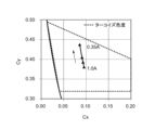
- FIG. 6 is a chromaticity diagram showing changes in chromaticity in an example of a conventional lighting device that emits light of turquoise blue color.
- the horizontal axis in FIG. 6 indicates chromaticity Cx, and the vertical axis indicates chromaticity Cy.
- the range surrounded by the broken line in the chromaticity diagram indicates the chromaticity range of turquoise blue.
- the triangular marks shown in the chromaticity diagram indicate changes in the chromaticity diagram when the value of the current flowing through the lighting device changes at a temperature of 25°C.
- the chip size of the light emitting diode used is 1 mm 2 .
- the present invention has been made in view of the above-mentioned conventional problems, and provides a lighting device that can improve yield by relaxing the selection requirements for turquoise blue color and can also achieve uniform chromaticity.
- the purpose is to
- the lighting device of the present invention includes a first light emitting element that emits first light belonging to a first chromaticity rank, and a second light emitting element that emits second light belonging to a second chromaticity rank. and a light mixing unit that mixes the first light and the second light and irradiates the mixture as irradiation light, the first chromaticity rank and the second chromaticity rank are different, and the irradiation The light is characterized by being within the turquoise chromaticity range.
- the first light belonging to the first chromaticity rank and the second light belonging to the second chromaticity rank are mixed in the light mixing section, and the first chromaticity rank and the second color are mixed. Even if the chromaticity rank is different, the irradiated light is included in the turquoise blue chromaticity range, so it is possible to ease the selection requirements for turquoise blue color, improve yield, and achieve uniform chromaticity. .
- the first chromaticity rank and the second chromaticity rank include overlapping chromaticity ranges that are common chromaticity ranges.
- At least one of the first chromaticity rank and the second chromaticity rank also includes an external chromaticity range that is outside the chromaticity range of the turquoise blue.
- the chromaticity of the first light emitting element and the second light emitting element change in opposite directions with respect to temperature change.
- the first light emitting element and the second light emitting element each include a different wavelength conversion member.
- the chromaticity range of the turquoise blue corresponds to a wavelength of 485 nm or more and 500 nm or less.
- the present invention it is possible to provide a lighting device that can improve the yield by relaxing the selection requirements for turquoise blue color, and can also achieve uniform chromaticity.
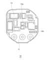
- FIG. 2 is a schematic plan view showing a configuration example of a light emitting section 10 used in the lighting device 100 according to the first embodiment.
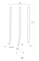
- FIG. 1 is an exploded view schematically showing a configuration example of a lighting device 100 according to a first embodiment. It is a chromaticity diagram showing the relationship between the first light, the second light, and the irradiation light in the lighting device 100 according to the first embodiment. It is a chromaticity diagram which shows the example of a combination of the 1st chromaticity rank and the 2nd chromaticity rank in the illuminating device 100 based on the modification of 1st Embodiment.
- FIG. 5(a) shows a case where the wavelength becomes shorter as the temperature rises.
- (b) shows the case where the wavelength becomes longer as the temperature rises.
- FIG. 2 is a chromaticity diagram showing changes in chromaticity in an example of a conventional lighting device that emits light of turquoise blue color.
- FIG. 1 is a schematic plan view showing a configuration example of a light emitting section 10 used in a lighting device 100 according to the present embodiment.
- the light emitting unit 10 is a part of the lighting device 100 that emits light.
- the light emitting section 10 includes a mounting section 11, light emitting elements 12a and 12b, and an electronic component 13.
- the mounting portion 11 is a member on which a wiring pattern (not shown) is formed and on which the light emitting elements 12a, 12b and the electronic component 13 are mounted.
- the configuration of the mounting section 11 is not limited, and known materials and structures such as a normal printed wiring board, a ceramic board, a resin board, etc. can be used.
- the light emitting elements 12a and 12b are optical components that are mounted on the mounting portion 11 and emit light at a predetermined wavelength when supplied with electric power, and correspond to the first light emitting element and the second light emitting element in the present invention. .
- the first light and the second light emitted by the light emitting elements 12a and 12b belong to the first chromaticity rank and the second chromaticity rank, respectively. Further, as will be described later, the first light and the second light emitted by the light emitting elements 12a and 12b are mixed in the light mixing unit 20 to form irradiation light, and the irradiation light belongs to the chromaticity range of turquoise blue chromaticity. Become something.
- the configuration of the light emitting elements 12a and 12b is not limited, an LED package that combines a light emitting diode (LED) that emits primary light and a wavelength conversion member that converts a part of the primary light into secondary light may be used. Can be used. Further, the material of the light emitting diode is not limited either, and known materials and structures can be used. As an example, a GaN-based LED that emits blue light can be used. Moreover, the material of the wavelength conversion member is not limited either. In the light emitting elements 12a and 12b, a part of the primary light emitted by the light emitting diode is converted into secondary light by the wavelength conversion member, and the remaining primary light and secondary light that are not converted are converted into the first chromaticity rank.
- LED light emitting diode
- a wavelength conversion member that converts a part of the primary light into secondary light
- the light emitting elements 12a and 12b may be provided with different wavelength conversion members and have different characteristics of chromaticity change due to temperature change or current change.
- the size of the light emitting elements 12a and 12b is not limited, as an example, one having a chip size of 1 mm 2 can be used.
- the electronic component 13 is a component that is mounted on the mounting section 11 and performs a predetermined operation when power is supplied.
- As the type of electronic component 13 known resistors, diodes, transistors, coils, ICs (Integrated Circuits), etc. can be used.
- the wiring pattern provided on the mounting portion 11, the light emitting elements 12a, 12b, and the electronic component 13 constitute a circuit for driving the light emitting elements 12a, 12b.
- FIG. 2 is an exploded view schematically showing a configuration example of the lighting device 100 according to the present embodiment.
- the lighting device 100 is configured by combining a light emitting section 10 and a light mixing section 20.
- the light mixing section 20 is a section that mixes the first light and the second light from the light emitting elements 12a and 12b included in the light emitting section 10 and irradiates the mixed light to the outside as irradiation light.
- the light mixing section 20 is configured by a combination of a reflector 21, a light guiding member 22, and a light diffusing member 23.
- the reflector 21 is an optical member that is placed behind the light guide member 22 and reflects at least a portion of the light emitted from the light guide member 22 on a reflective surface. The light reflected by the reflector 21 is irradiated to the outside of the lighting device 100 via the light guide member 22 and the light diffusion member 23.
- the material constituting the reflector 21 is not limited, it is possible to use a conventionally known resin material or the like, whose surface is coated with a high reflectance coating.
- a highly reflective film or the like may be formed on the side surface of the light guide member 22 and the reflector 21 may be omitted.
- the light guide member 22 is an optical member that is made of a material that transmits light, guides light along the extension direction, and irradiates the guided light from the side.
- a light entrance part is provided at one end of the light guide member 22, and the light emitting part 10 is arranged opposite to the light entrance part.
- Concave and convex steps are formed along the side surface of the light guide member 22, and the light guided inside is reflected by the concave and convex steps and irradiated to the outside of the light guide member 22 from the side surface.
- a substantially cylindrical light pipe is shown as the light guide member 22, but it may be a plate shape, and the specific shape is not limited.
- the light diffusing member 23 is arranged on the light exit surface side of the light guide member 22, is made of a material that transmits at least a part of the light, and is a member that diffuses the light.
- the material constituting the light diffusing member 23 is not limited, and known resin materials and glass materials can be used.
- the structure for diffusing light in the light diffusing member 23 is not limited, and may include a structure in which light scattering particles having different refractive indexes are contained in a resin material, or a structure in which the front or back surface of the light diffusing member 23 is roughened. , a structure in which the light diffusing member 23 is a diffusing lens, etc. can be used.
- the light emitting elements 12a and 12b of the light emitting unit 10 when power is supplied to the light emitting elements 12a and 12b of the light emitting unit 10, the light emitting elements 12a and 12b emit first light and second light, respectively.
- the first light and the second light emitted by the light emitting unit 10 are partially reflected by the reflector 21 while propagating inside the light guide member 22 in the longitudinal direction, and the other part is reflected by the uneven steps, so that the light is The light enters the light diffusing member 23 from the exit surface side.
- the light incident on the light diffusing member 23 is diffused by a light diffusing structure provided in the light diffusing member 23 and is irradiated to the outside as irradiation light.
- the irradiated light at this time is a mixture of the first light and the second light due to reflection by the light guiding member 22 and reflector 21 and diffusion by the light diffusing member 23, and belongs to the chromaticity range of turquoise blue chromaticity. It becomes.
- FIG. 3 is a chromaticity diagram showing the relationship between the first light, the second light, and the irradiation light in the lighting device 100 according to the present embodiment.
- the horizontal axis in FIG. 3 indicates chromaticity Cx, and the vertical axis indicates chromaticity Cy.
- the chromaticity range of turquoise blue (Cx, Cy) is (0.012, 0.495), (0.200, 0.400), (0.200, 0.320), (0.040). , 0.320), and has a wavelength of 485 nm or more and 500 nm or less.
- the trapezoidal range surrounded by a broken line in the chromaticity diagram indicates the chromaticity range of the first chromaticity rank
- the trapezoidal range surrounded by a dashed-dotted line indicates the chromaticity range of the second chromaticity rank. It shows.
- the straight line shown in the figure shows the chromaticity change when the current changes or the temperature changes
- the broken line shows the first light of the light emitting element 12a
- the dashed line shows the second light of the light emitting element 12b
- the solid line indicates the irradiated light from the light mixing section 20.
- the first chromaticity ranks (Cx, Cy) are (0.012, 0.495), (0.200, 0.400), (0.200, 0.360). , (0.040, 0.360).
- the second chromaticity ranks (Cx, Cy) are (0.012, 0.430), (0.200, 0.370), (0.200, 0.320), (0.040, 0.320) within a trapezoidal range surrounded by four points. Therefore, the first chromaticity rank and the second chromaticity rank are (0.012, 0.430), (0.200, 0.370) (0.200, 0.360), (0.040, 0
- a trapezoidal shape surrounded by four points (.360) is common as the overlapping chromaticity range.
- the light emitting element 12a has a characteristic that the chromaticity changes within the range along the broken line shown in FIG. 3 when the current value (current density) changes, and belongs to the first chromaticity rank. are ranked.
- the light emitting element 12b has a characteristic that when the current value (current density) changes, the chromaticity changes within the range along the dashed line shown in FIG. They are ranked according to their belonging.
- the ranking of the light emitting elements 12a and 12b when the current changes is determined by placing the light emitting elements 12a and 12b respectively inside an integrating sphere whose temperature is kept constant, and supplying a pulsed current by changing the current value. This can be done by measuring the actual chromaticity using a spectrometer.
- the manufacturers of the light emitting elements 12a and 12b may conduct a characteristic test beforehand at the time of shipment and rank them.
- the irradiation light is a mixture of the first light and the second light, so if the amounts of both lights are the same, the chromaticity will be intermediate, and the chromaticity will change within the range along the solid line shown in Figure 3. will change. Therefore, the irradiated light also falls within the chromaticity range of turquoise blue. Further, the chromaticity of the irradiated light is intermediate between the first light and the second light, and therefore the chromaticity is closer to the center of the turquoise blue chromaticity range than the first light and the second light.
- FIG. 3 shows the change in chromaticity when the current value changes, a similar effect can be obtained by changing the chromaticity when the temperature changes.
- the light emitting elements 12a and 12b are placed inside an integrating sphere, and the chromaticity is measured using a spectrometer when the same current is supplied at different temperatures. This can be done by
- the first light belonging to the first chromaticity rank and the second light belonging to the second chromaticity rank are mixed in the light mixing unit 20, so that the first color Even if the chromaticity rank and the second chromaticity rank are different, the irradiated light is included in the turquoise blue chromaticity range. This makes it possible to improve the yield by relaxing the selection requirements for the turquoise blue color and to make the chromaticity uniform.
- FIG. 4 is a chromaticity diagram showing an example of the combination of the first chromaticity rank and the second chromaticity rank in the lighting device 100 according to this modification.
- a case is shown in which both the first chromaticity rank and the second chromaticity rank are included in the chromaticity range of turquoise blue, but in this modification, the first chromaticity rank or the second chromaticity rank is At least one of the chromaticity ranks also includes an external chromaticity range that is outside the turquoise blue chromaticity range.
- the first chromaticity ranks (Cx, Cy) are (0.063, 0.364), (0.200, 0.317), (0.200, 0 .302), (0.076, 0.280).
- the second chromaticity ranks (Cx, Cy) are (0.050, 0.430), (0.200, 0.327), (0.200, 0.312), (0.068, 0.335) within a trapezoidal range surrounded by four points.
- the first chromaticity ranks (Cx, Cy) are (0.057, 0.381), (0.194, 0.334), (0.194, 0 .319), (0.070, 0.297).
- the second chromaticity ranks (Cx, Cy) are (0.044, 0.447), (0.194, 0.344), (0.194, 0.329), (0.062, 0.352) within a trapezoidal range surrounded by four points.
- the first chromaticity ranks (Cx, Cy) are (0.053, 0.397), (0.200, 0.348), (0.200, 0 .306), (0.070, 0.283).
- the second chromaticity ranks (Cx, Cy) are (0.041, 0.485), (0.200, 0.376), (0.200, 0.334), (0.060, 0.359) within a trapezoidal range surrounded by four points.
- the first chromaticity ranks (Cx, Cy) are (0.047, 0.414), (0.195, 0.365), (0.195, 0 .323), (0.064, 0.300).
- the second chromaticity ranks (Cx, Cy) are (0.035, 0.502), (0.195, 0.393), (0.195, 0.351), (0.054, 0.502) within a trapezoidal range surrounded by four points.
- the first chromaticity rank or the second chromaticity rank includes an external chromaticity range outside the turquoise blue chromaticity range.
- the irradiation light mixes the first light and the second light and has a chromaticity intermediate between the two, so even if one uses a chromaticity rank that includes the external chromaticity range, the irradiation light The light can be in the turquoise chromaticity range.
- the first chromaticity rank and the second chromaticity rank at the upper and lower sides of the turquoise blue chromaticity range. More specifically, in the chromaticity range of turquoise blue, a part of the intermediate line connecting two points (0.200, 0.360) and (0.008, 0,418), which are the intermediate points of Cy, is an overlapping color. Preferably, it is within the range of Further, it is preferable that regions of the first chromaticity rank and the second chromaticity rank that are not included in the overlapping chromaticity range are located above and below the intermediate line.
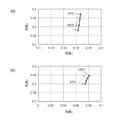
- FIG. 5 is a chromaticity diagram illustrating the temperature characteristics of the first light and the second light in the illumination device 100 according to the present embodiment, and FIG. 5(a) shows a case where the wavelength becomes shorter as the temperature rises. , FIG. 5(b) shows the case where the wavelength becomes longer as the temperature rises.
- the light-emitting elements 12a and 12b had a chip size of 1 mm 2 and were measured at a constant current value (current density).
- the light emitting elements 12a and 12b whose chromaticity change characteristics change in opposite directions are made using different wavelength conversion members, so that when the wavelength of the primary light changes in the longer wavelength direction, the light amount of the secondary light changes. Examples include using increasing and decreasing materials. In this case, the chromaticity of the light emitted from the light emitting elements 12a and 12b may change in opposite directions due to the longer wavelength of the primary light and the increase/decrease of the secondary light. Alternatively, the types of light emitting diodes included in the light emitting elements 12a and 12b may be different.
- the light-emitting elements 12a and 12b have the chromaticity change characteristics shown in FIGS. 5(a) and 5(b), respectively.
- the chromaticity of the light emitting element 12a changes from (0.168, 0.375) to (0.163, 0.275).
- the chromaticity of the light emitting element 12b changes from (0.074, 0.400) to (0.081, 0.448).
- the chromaticity of the light emitting elements 12a and 12b changes in the direction in which the chromaticity Cy decreases and in the direction in which it increases as the temperature rises, and the chromaticity changes in the opposite direction with respect to temperature changes.
- the light emitting elements 12a and 12b belong to different chromaticity ranks.
- the chromaticity of the irradiated light changes from (0.121, 0.388), which is between the two, to (0.122, 0.362).
- This irradiation light belongs to the chromaticity range of turquoise blue, and the chromaticity change is smaller than the chromaticity change between the first light and the second light.
- FIG. 5 shows the change in chromaticity when the temperature changes, a similar effect can be obtained by changing the chromaticity when the current changes.
- the first light belonging to the first chromaticity rank and the second light belonging to the second chromaticity rank are mixed in the light mixing unit 20, so that the first light belonging to the first chromaticity rank and the second light belonging to the second chromaticity rank are mixed. Even if the second chromaticity ranks are different, the irradiated light is included in the turquoise blue chromaticity range. Further, since the light emitting element 12a and the light emitting element 12b have a characteristic that the chromaticity changes in opposite directions with respect to temperature change, it is possible to suppress a change in the chromaticity of the irradiated light that is a mixture of the two. This makes it possible to improve the yield by relaxing the selection requirements for the turquoise blue color and to make the chromaticity uniform.
Landscapes
- Engineering & Computer Science (AREA)
- Physics & Mathematics (AREA)
- Microelectronics & Electronic Packaging (AREA)
- Optics & Photonics (AREA)
- General Engineering & Computer Science (AREA)
- Non-Portable Lighting Devices Or Systems Thereof (AREA)
- Led Device Packages (AREA)
- Planar Illumination Modules (AREA)
- Electroluminescent Light Sources (AREA)
Abstract
Description
以下、本発明の実施形態について、図面を参照して詳細に説明する。各図面に示される同一または同等の構成要素、部材、処理には、同一の符号を付すものとし、適宜重複した説明は省略する。図1は、本実施形態に係る照明装置100に用いられる発光部10の構成例を示す模式平面図である。発光部10は、照明装置100において光を発光する部分である。図1に示すように発光部10は、搭載部11と、発光素子12a,12bと、電子部品13を備えている。
図4は、本変形例に係る照明装置100における第1色度ランクと第2色度ランクの組み合わせ例を示す色度図である。第1実施形態では、第1色度ランクと第2色度ランクが共にターコイズブルーの色度範囲に含まれた場合を示しているが、本変形例においては、第1色度ランクまたは第2色度ランクの少なくとも一方は、ターコイズブルーの色度範囲外である外部色度範囲も含んでいる。
次に、本発明の第2実施形態について図5を用いて説明する。第1実施形態と重複する内容は説明を省略する。第1実施形態では発光素子12a,12bとして温度変化や電流変化に対する色度変化が同じ傾向のものを用いたが、本実施形態では互いに逆方向に色度が変化する特性のものを用いる。図5は、本実施形態に係る照明装置100における第1光と第2光の温度特性を説明する色度図であり、図5(a)は温度上昇に伴って波長が短くなる場合を示し、図5(b)は温度上昇に伴って波長が長くなる場合を示している。発光素子12a,12bはチップサイズが1mm2のものを用い、電流値(電流密度)を一定にして測定した。
10…発光部
20…光混合部
11…搭載部
12a,12b…発光素子
13…電子部品
21…リフレクター
22…導光部材
23…光拡散部材
Claims (6)
- 第1色度ランクに属する第1光を発光する第1発光素子と、
第2色度ランクに属する第2光を発光する第2発光素子と、
前記第1光と前記第2光を混合して照射光として外部に照射する光混合部とを備え、
前記第1色度ランクと前記第2色度ランクは異なっており、前記照射光はターコイズブルーの色度範囲に含まれることを特徴とする照明装置。 - 請求項1に記載の照明装置であって、
前記第1色度ランクおよび前記第2色度ランクは、共通する色度範囲である重複色度範囲を含んでいることを特徴とする照明装置。 - 請求項1に記載の照明装置であって、
前記第1色度ランクまたは前記第2色度ランクの少なくとも一方は、前記ターコイズブルーの色度範囲外である外部色度範囲も含んでいることを特徴とする照明装置。 - 請求項1に記載の照明装置であって、
前記第1発光素子と前記第2発光素子は、温度変化に対して逆方向に色度が変化することを特徴とする照明装置。 - 請求項4に記載の照明装置であって、
前記第1発光素子および前記第2発光素子は、それぞれ異なる波長変換部材を備えていることを特徴とする照明装置。 - 請求項1から5の何れか一つに記載の照明装置であって、
前記ターコイズブルーの色度範囲は、485nm以上500nm以下の波長に対応していることを特徴とする照明装置。
Priority Applications (3)
| Application Number | Priority Date | Filing Date | Title |
|---|---|---|---|
| EP23796160.2A EP4517157A4 (en) | 2022-04-26 | 2023-04-17 | LIGHTING DEVICE |
| CN202380030689.XA CN119013513A (zh) | 2022-04-26 | 2023-04-17 | 照明装置 |
| US18/853,753 US12486953B2 (en) | 2022-04-26 | 2023-04-17 | Lighting device |
Applications Claiming Priority (2)
| Application Number | Priority Date | Filing Date | Title |
|---|---|---|---|
| JP2022-072787 | 2022-04-26 | ||
| JP2022072787A JP7825503B2 (ja) | 2022-04-26 | 2022-04-26 | 照明装置 |
Publications (1)
| Publication Number | Publication Date |
|---|---|
| WO2023210417A1 true WO2023210417A1 (ja) | 2023-11-02 |
Family
ID=88518557
Family Applications (1)
| Application Number | Title | Priority Date | Filing Date |
|---|---|---|---|
| PCT/JP2023/015271 Ceased WO2023210417A1 (ja) | 2022-04-26 | 2023-04-17 | 照明装置 |
Country Status (5)
| Country | Link |
|---|---|
| US (1) | US12486953B2 (ja) |
| EP (1) | EP4517157A4 (ja) |
| JP (1) | JP7825503B2 (ja) |
| CN (1) | CN119013513A (ja) |
| WO (1) | WO2023210417A1 (ja) |
Citations (4)
| Publication number | Priority date | Publication date | Assignee | Title |
|---|---|---|---|---|
| JP2010218991A (ja) * | 2009-03-19 | 2010-09-30 | Hitachi Ltd | 照明装置並びにこれを用いた液晶表示装置及び映像表示装置 |
| JP2013030594A (ja) * | 2011-07-28 | 2013-02-07 | Nichia Chem Ind Ltd | 発光装置の製造方法および発光装置 |
| WO2020080132A1 (ja) | 2018-10-19 | 2020-04-23 | 株式会社小糸製作所 | 発光装置および車両用灯具の発光装置シリーズ |
| JP2022072787A (ja) | 2020-10-30 | 2022-05-17 | 小林製薬株式会社 | 口腔用組成物 |
Family Cites Families (11)
| Publication number | Priority date | Publication date | Assignee | Title |
|---|---|---|---|---|
| US8783887B2 (en) * | 2007-10-01 | 2014-07-22 | Intematix Corporation | Color tunable light emitting device |
| JP5217800B2 (ja) * | 2008-09-03 | 2013-06-19 | 日亜化学工業株式会社 | 発光装置、樹脂パッケージ、樹脂成形体並びにこれらの製造方法 |
| JP2012109532A (ja) * | 2010-09-08 | 2012-06-07 | Mitsubishi Chemicals Corp | 発光装置、照明装置、及びレンズ |
| DE102013211525A1 (de) * | 2013-06-19 | 2014-12-24 | Osram Gmbh | LED-Modul mit LED-Chips |
| JP6455817B2 (ja) * | 2014-09-12 | 2019-01-23 | パナソニックIpマネジメント株式会社 | 照明装置 |
| JP6877342B2 (ja) * | 2014-12-16 | 2021-05-26 | シグニファイ ホールディング ビー ヴィSignify Holding B.V. | 照明装置、照明システム、並びに前記照明装置及び前記照明システムの使用 |
| ITUB20153566A1 (it) * | 2015-09-11 | 2017-03-11 | Clay Paky Spa | Modulo di illuminazione a led e gruppo di illuminazione avente moduli di illuminazione a led |
| KR20180021434A (ko) * | 2016-08-22 | 2018-03-05 | 이주동 | Led집어등장치 |
| US10502374B2 (en) * | 2017-01-30 | 2019-12-10 | Ideal Industries Lighting Llc | Light fixtures and methods |
| US11330686B2 (en) * | 2018-08-31 | 2022-05-10 | Signify Holding B.V. | Cyan enriched white light |
| WO2020209295A1 (ja) * | 2019-04-11 | 2020-10-15 | 株式会社小糸製作所 | 車両用灯具およびその点灯回路 |
-
2022
- 2022-04-26 JP JP2022072787A patent/JP7825503B2/ja active Active
-
2023
- 2023-04-17 EP EP23796160.2A patent/EP4517157A4/en active Pending
- 2023-04-17 WO PCT/JP2023/015271 patent/WO2023210417A1/ja not_active Ceased
- 2023-04-17 US US18/853,753 patent/US12486953B2/en active Active
- 2023-04-17 CN CN202380030689.XA patent/CN119013513A/zh active Pending
Patent Citations (4)
| Publication number | Priority date | Publication date | Assignee | Title |
|---|---|---|---|---|
| JP2010218991A (ja) * | 2009-03-19 | 2010-09-30 | Hitachi Ltd | 照明装置並びにこれを用いた液晶表示装置及び映像表示装置 |
| JP2013030594A (ja) * | 2011-07-28 | 2013-02-07 | Nichia Chem Ind Ltd | 発光装置の製造方法および発光装置 |
| WO2020080132A1 (ja) | 2018-10-19 | 2020-04-23 | 株式会社小糸製作所 | 発光装置および車両用灯具の発光装置シリーズ |
| JP2022072787A (ja) | 2020-10-30 | 2022-05-17 | 小林製薬株式会社 | 口腔用組成物 |
Non-Patent Citations (1)
| Title |
|---|
| See also references of EP4517157A4 |
Also Published As
| Publication number | Publication date |
|---|---|
| JP7825503B2 (ja) | 2026-03-06 |
| EP4517157A4 (en) | 2025-12-17 |
| US20250224085A1 (en) | 2025-07-10 |
| JP2023162070A (ja) | 2023-11-08 |
| EP4517157A1 (en) | 2025-03-05 |
| CN119013513A (zh) | 2024-11-22 |
| US12486953B2 (en) | 2025-12-02 |
Similar Documents
| Publication | Publication Date | Title |
|---|---|---|
| US7235817B2 (en) | LED Lamp | |
| US20200278103A1 (en) | Light emitting device | |
| KR100830072B1 (ko) | 조명 장치 및 조명 장치를 이용하는 lcd 디바이스 | |
| US7217004B2 (en) | Light emitting diode array module for providing backlight and backlight unit having the same | |
| JP4837626B2 (ja) | 自動車用室内灯 | |
| US8960932B2 (en) | Light emitting device | |
| US20060221610A1 (en) | Light-emitting apparatus having a plurality of overlapping panels forming recesses from which light is emitted | |
| US20120194068A1 (en) | Lamp having light sensor | |
| JP5532329B2 (ja) | 照明装置 | |
| JP2013232644A (ja) | 発光装置 | |
| TWI520383B (zh) | 發光二極體封裝結構 | |
| CN103486511A (zh) | 灯单元以及使用该灯单元的车辆 | |
| WO2013018902A1 (ja) | 発光体を用いた面照明光源装置 | |
| WO2013183675A1 (ja) | エッジライト型面光源装置および照明装置 | |
| US7850336B2 (en) | Light emitting module and display device having the same | |
| WO2023210417A1 (ja) | 照明装置 | |
| JP2010086670A (ja) | 面光源装置 | |
| WO2024034459A1 (ja) | 光学部材および照明装置 | |
| JP6923832B2 (ja) | 発光装置 | |
| CN104487883B (zh) | 用于提供电磁射束的射束装置 | |
| JP6773156B2 (ja) | 発光装置 | |
| JP5851608B2 (ja) | エッジライト型面光源装置 | |
| JP2023516203A (ja) | 光源モジュール | |
| JP2021176152A (ja) | 発光装置 | |
| JP2008152983A (ja) | Led照明器具 |
Legal Events
| Date | Code | Title | Description |
|---|---|---|---|
| 121 | Ep: the epo has been informed by wipo that ep was designated in this application |
Ref document number: 23796160 Country of ref document: EP Kind code of ref document: A1 |
|
| WWE | Wipo information: entry into national phase |
Ref document number: 202380030689.X Country of ref document: CN |
|
| WWE | Wipo information: entry into national phase |
Ref document number: 18853753 Country of ref document: US |
|
| WWE | Wipo information: entry into national phase |
Ref document number: 2023796160 Country of ref document: EP |
|
| NENP | Non-entry into the national phase |
Ref country code: DE |
|
| ENP | Entry into the national phase |
Ref document number: 2023796160 Country of ref document: EP Effective date: 20241126 |
|
| WWP | Wipo information: published in national office |
Ref document number: 18853753 Country of ref document: US |