WO2023210513A1 - 鉛蓄電池およびその製造方法、および使用方法 - Google Patents
鉛蓄電池およびその製造方法、および使用方法 Download PDFInfo
- Publication number
- WO2023210513A1 WO2023210513A1 PCT/JP2023/015844 JP2023015844W WO2023210513A1 WO 2023210513 A1 WO2023210513 A1 WO 2023210513A1 JP 2023015844 W JP2023015844 W JP 2023015844W WO 2023210513 A1 WO2023210513 A1 WO 2023210513A1
- Authority
- WO
- WIPO (PCT)
- Prior art keywords
- lead
- positive electrode
- acid battery
- mass
- negative electrode
- Prior art date
- Legal status (The legal status is an assumption and is not a legal conclusion. Google has not performed a legal analysis and makes no representation as to the accuracy of the status listed.)
- Ceased
Links
Images
Classifications
-
- H—ELECTRICITY
- H01—ELECTRIC ELEMENTS
- H01M—PROCESSES OR MEANS, e.g. BATTERIES, FOR THE DIRECT CONVERSION OF CHEMICAL ENERGY INTO ELECTRICAL ENERGY
- H01M4/00—Electrodes
- H01M4/02—Electrodes composed of, or comprising, active material
- H01M4/14—Electrodes for lead-acid accumulators
-
- H—ELECTRICITY
- H01—ELECTRIC ELEMENTS
- H01M—PROCESSES OR MEANS, e.g. BATTERIES, FOR THE DIRECT CONVERSION OF CHEMICAL ENERGY INTO ELECTRICAL ENERGY
- H01M10/00—Secondary cells; Manufacture thereof
- H01M10/42—Methods or arrangements for servicing or maintenance of secondary cells or secondary half-cells
- H01M10/52—Removing gases inside the secondary cell, e.g. by absorption
- H01M10/523—Removing gases inside the secondary cell, e.g. by absorption by recombination on a catalytic material
-
- H—ELECTRICITY
- H01—ELECTRIC ELEMENTS
- H01M—PROCESSES OR MEANS, e.g. BATTERIES, FOR THE DIRECT CONVERSION OF CHEMICAL ENERGY INTO ELECTRICAL ENERGY
- H01M4/00—Electrodes
- H01M4/02—Electrodes composed of, or comprising, active material
- H01M4/36—Selection of substances as active materials, active masses, active liquids
- H01M4/48—Selection of substances as active materials, active masses, active liquids of inorganic oxides or hydroxides
- H01M4/56—Selection of substances as active materials, active masses, active liquids of inorganic oxides or hydroxides of lead
- H01M4/57—Selection of substances as active materials, active masses, active liquids of inorganic oxides or hydroxides of lead of "grey lead", i.e. powders containing lead and lead oxide
-
- H—ELECTRICITY
- H01—ELECTRIC ELEMENTS
- H01M—PROCESSES OR MEANS, e.g. BATTERIES, FOR THE DIRECT CONVERSION OF CHEMICAL ENERGY INTO ELECTRICAL ENERGY
- H01M4/00—Electrodes
- H01M4/02—Electrodes composed of, or comprising, active material
- H01M4/62—Selection of inactive substances as ingredients for active masses, e.g. binders, fillers
-
- H—ELECTRICITY
- H01—ELECTRIC ELEMENTS
- H01M—PROCESSES OR MEANS, e.g. BATTERIES, FOR THE DIRECT CONVERSION OF CHEMICAL ENERGY INTO ELECTRICAL ENERGY
- H01M4/00—Electrodes
- H01M4/02—Electrodes composed of, or comprising, active material
- H01M4/62—Selection of inactive substances as ingredients for active masses, e.g. binders, fillers
- H01M4/624—Electric conductive fillers
- H01M4/625—Carbon or graphite
-
- H—ELECTRICITY
- H01—ELECTRIC ELEMENTS
- H01M—PROCESSES OR MEANS, e.g. BATTERIES, FOR THE DIRECT CONVERSION OF CHEMICAL ENERGY INTO ELECTRICAL ENERGY
- H01M4/00—Electrodes
- H01M4/02—Electrodes composed of, or comprising, active material
- H01M4/62—Selection of inactive substances as ingredients for active masses, e.g. binders, fillers
- H01M4/628—Inhibitors, e.g. gassing inhibitors, corrosion inhibitors
-
- H—ELECTRICITY
- H01—ELECTRIC ELEMENTS
- H01M—PROCESSES OR MEANS, e.g. BATTERIES, FOR THE DIRECT CONVERSION OF CHEMICAL ENERGY INTO ELECTRICAL ENERGY
- H01M2220/00—Batteries for particular applications
- H01M2220/20—Batteries in motive systems, e.g. vehicle, ship, plane
-
- H—ELECTRICITY
- H01—ELECTRIC ELEMENTS
- H01M—PROCESSES OR MEANS, e.g. BATTERIES, FOR THE DIRECT CONVERSION OF CHEMICAL ENERGY INTO ELECTRICAL ENERGY
- H01M2300/00—Electrolytes
- H01M2300/0002—Aqueous electrolytes
- H01M2300/0005—Acid electrolytes
- H01M2300/0011—Sulfuric acid-based
-
- Y—GENERAL TAGGING OF NEW TECHNOLOGICAL DEVELOPMENTS; GENERAL TAGGING OF CROSS-SECTIONAL TECHNOLOGIES SPANNING OVER SEVERAL SECTIONS OF THE IPC; TECHNICAL SUBJECTS COVERED BY FORMER USPC CROSS-REFERENCE ART COLLECTIONS [XRACs] AND DIGESTS
- Y02—TECHNOLOGIES OR APPLICATIONS FOR MITIGATION OR ADAPTATION AGAINST CLIMATE CHANGE
- Y02E—REDUCTION OF GREENHOUSE GAS [GHG] EMISSIONS, RELATED TO ENERGY GENERATION, TRANSMISSION OR DISTRIBUTION
- Y02E60/00—Enabling technologies; Technologies with a potential or indirect contribution to GHG emissions mitigation
- Y02E60/10—Energy storage using batteries
-
- Y—GENERAL TAGGING OF NEW TECHNOLOGICAL DEVELOPMENTS; GENERAL TAGGING OF CROSS-SECTIONAL TECHNOLOGIES SPANNING OVER SEVERAL SECTIONS OF THE IPC; TECHNICAL SUBJECTS COVERED BY FORMER USPC CROSS-REFERENCE ART COLLECTIONS [XRACs] AND DIGESTS
- Y02—TECHNOLOGIES OR APPLICATIONS FOR MITIGATION OR ADAPTATION AGAINST CLIMATE CHANGE
- Y02P—CLIMATE CHANGE MITIGATION TECHNOLOGIES IN THE PRODUCTION OR PROCESSING OF GOODS
- Y02P70/00—Climate change mitigation technologies in the production process for final industrial or consumer products
- Y02P70/50—Manufacturing or production processes characterised by the final manufactured product
Definitions
- the present invention relates to lead-acid batteries.
- a lead-acid battery includes a negative plate, a positive plate, a separator (or mat), an electrolyte, and the like. Each plate includes a current collector and an electrode material.
- Patent Document 1 proposes a positive electrode current collector for lead-acid batteries that contains a carbonaceous material at least on the surface.
- Patent Document 2 discloses a method for manufacturing a lead-acid battery in which after forming a battery, the electrolyte is removed and a control valve is attached, in which 80% by mass or more of lead dioxide (PbO 2 ) is present in the positive electrode active material after the formation.
- PbO 2 lead dioxide
- Patent Document 3 includes a positive electrode plate, a negative electrode plate, and an electrolytic solution, the negative electrode plate is provided with a negative electrode material, the negative electrode material contains a carbon material and an organic shrink-proofing agent, and the negative electrode material includes a carbon material and an organic preshrink agent.
- the content Ce (mass %) of the organic shrink-proofing agent in the negative electrode material is calculated by the following formula: (1): (f(S ⁇ Ccn)+0.10) ⁇ Ce ⁇ (f(S ⁇ Ccn)+0.25) is satisfied, and f(S ⁇ Ccn) is calculated by the following formula (2): ( ⁇ 7 .3 ⁇ 10 ⁇ 7 ⁇ S2+0.0010 ⁇ S) ⁇ Ccn ⁇ f(S ⁇ Ccn) ⁇ ( ⁇ 8.0 ⁇ 10 ⁇ 7 ⁇ S2+0.0011 ⁇ S+0.070) ⁇ Ccn, and the carbon material
- the proposed lead-acid battery has an external specific surface area S of 1.5 m 2 /g or more and 680 m 2 /g or less.
- Patent Document 4 discloses a battery case including a battery case having a cell chamber and an open top surface, an electrode plate group and an electrolytic solution housed in the cell chamber, and a lid that closes the opening.
- the plate group has a negative electrode and a positive electrode
- the negative electrode includes a negative electrode active material containing a Pb component, ligninsulfonic acid and/or a salt thereof, and a carbon material having a specific surface area of 10.0 m 2 /g or less.
- Patent Document 5 discloses that after a battery is manufactured using unformed positive and negative electrode plates, a predetermined dilute sulfuric acid is injected into the battery and energized to chemically form these electrode plates in a battery case.
- a sealed lead-acid battery produced by the so-called container chemical process, which is characterized by using a negative electrode active material to which fatty acid or its salt is added along with lignin or its derivative. .
- Lead-acid batteries are sometimes used in an undercharged state called a partial state of charge (PSOC).
- PSOC partial state of charge
- a lead-acid battery installed in a vehicle that is subjected to idle reduction control also referred to as Idle Reduction control, Start-Stop System, etc.
- Idle Reduction control also referred to as Idle Reduction control, Start-Stop System, etc.
- PSOC partial state of charge
- lead-acid batteries used in PSOC stratification tends to progress, so suppression of sulfation is often considered important.
- lead-acid batteries used in PSOCs are rarely overcharged or charged to a fully charged state. Therefore, it has been thought that corrosion of the positive electrode current collector and liquid loss due to water electrolysis are unlikely to be a problem.
- the main objective of the present disclosure is to improve the cycle durability of lead-acid batteries used in PSOC.
- the present disclosure aims to improve the corrosion resistance of a positive electrode current collector and suppress the loss of electrolyte solution.
- One aspect of the present invention includes a positive electrode, a negative electrode, and an electrolyte, the positive electrode including a positive current collector, and a positive electrode material, and the negative electrode including a negative current collector and a negative electrode.
- material the positive electrode material contains lead dioxide
- the electrolyte contains water and sulfuric acid, and in a virtual fully charged state when the lead acid battery is assumed to be in a fully charged state.
- the content of lead dioxide in the positive electrode material is 70% by mass or more and 82% by mass or less.
- Another aspect of the present invention includes a step of assembling an unformed cell including a positive electrode, a negative electrode, and an electrolyte, and a step of chemically converting the unformed cell, wherein the positive electrode is a positive electrode assembly.
- the positive electrode is a positive electrode assembly.
- an electric body and a paste-type positive electrode material the positive electrode material contains lead dioxide
- the electrolytic solution contains water and sulfuric acid
- One of the purposes of the present disclosure is to improve the cycle durability of lead-acid batteries used in PSOC.
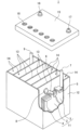
- FIG. 1 is a partially cutaway exploded perspective view showing the external appearance and internal structure of a lead-acid battery according to an embodiment of the present invention.
- a lead-acid battery includes a positive electrode, a negative electrode, and an electrolyte.
- the positive electrode includes a positive current collector and a positive electrode material.
- the negative electrode includes a negative electrode current collector and a negative electrode material.
- the electrolyte contains water and sulfuric acid.
- the positive electrode material includes lead dioxide.
- the positive electrode of a lead-acid battery installed in a vehicle that is subjected to idle-stop control is generally a paste-type positive electrode, which has a structure significantly different from that of a clad type.
- the positive electrode material is held by the positive current collector, and the negative electrode material is held by the negative current collector.
- the electrode material is the electrode plate minus the current collector.
- a member such as a mat or pasting paper may be attached to the electrode plate.
- Such a member also referred to as a pasting member
- the electrode plate includes an adhesive member (mat, pasting paper, etc.)
- the electrode material is exclusive of the current collector and the adhesive member.
- the lead-acid battery may include a container that houses the electrode plate group and the electrolyte.
- the electrode plate group is a laminate of a positive electrode and a negative electrode, and a separator is interposed between the positive electrode and the negative electrode.
- the lead-acid battery may be a liquid type battery (vented type battery) or a valve regulated type battery.
- a valve regulated lead-acid battery is also referred to as a VRLA (Valve Regulated Lead-Acid Battery).
- lead-acid batteries are not limited, their main use is assumed to be in PSOC.
- a lead-acid battery installed in a vehicle that is subjected to start-stop control is used in PSOC. Since lead-acid batteries used in PSOC are often used in an undercharged state, it is thought that corrosion of the positive electrode current collector and liquid loss due to water electrolysis are unlikely to be a problem.
- the content of lead dioxide (PbO 2 ) in the positive electrode material is controlled to be 70% by mass or more and 82% by mass or less. It has become clear that when the lead-acid battery is used, corrosion and liquid loss of the positive electrode current collector of the lead-acid battery are suppressed, and durability during charge/discharge cycles in PSOC is significantly improved.
- lead sulfate tends to remain in the positive electrode material when used in PSOC, and the It is presumed that the positive electrode potential is maintained more basely, and corrosion of the positive electrode current collector and water electrolysis are suppressed. Furthermore, since oxygen generation due to water electrolysis is suppressed, stress due to gas generation is reduced, and softening and falling off of the positive electrode material is also suppressed. This point is also considered to contribute to improving cycle durability.
- the content of lead dioxide (PbO 2 ) in the positive electrode material when the lead-acid battery is in a virtual fully charged state is preferably less than 80% by mass, more preferably 78% by mass or less, and 75% by mass. It is even more desirable that the amount is less than % by mass.
- Lead-acid batteries are inherently prone to stratification, where there is a difference in the specific gravity of the electrolyte (that is, a difference in the concentration of sulfuric acid) between the top and bottom of the battery case, and this tendency is even more pronounced in lead-acid batteries used in PSOC. It is. Stratification promotes deterioration of the negative electrode and softening of the upper part of the positive electrode, which causes a decrease in durability during charge/discharge cycles.
- the effect of controlling the content of lead dioxide in the positive electrode material to 70% by mass or more and 82% by mass or less tends to be limited to the upper part of the positive electrode.
- the above-mentioned effect is expressed throughout the positive electrode and is estimated to be more likely to become apparent.
- the present invention also includes a method of using the lead acid battery described above.
- a method of using such a lead-acid battery includes a step of charging and discharging the lead-acid battery mounted on a vehicle subjected to idling stop control using a PSOC.
- the method for using a lead-acid battery according to the present invention includes charging and discharging the lead-acid battery while the vehicle is under idling stop control, for example, so that the SOC is maintained in a range of 60% or more and 90% or less. It has a controlling process.
- the fully charged state of a lead-acid battery usually refers to a state where the actual state of charge (SOC) is 100%.
- the content rate of lead dioxide (PbO 2 ) in the positive electrode material in a virtual fully charged state is a calculated value determined by calculation.
- a state in which the specific gravity of the electrolyte is at a reference value is defined as a virtual fully charged state.
- the state of charge of lead-acid batteries used in PSOCs is often unknown. Furthermore, even when lead-acid batteries are not in use, the state of charge changes over time due to self-discharge, so the state of charge is often unknown.
- the specific gravity of the standard value is the value announced or disclosed by the manufacturer of the lead-acid battery, if it can be known from the announcement or disclosure by the manufacturer.
- the manufacturer may publish a design value for the specific gravity of the electrolyte in a fully charged state of a lead-acid battery. In that case, the design value may be used as the reference value. If the lead-acid battery manufacturer publishes or does not disclose the standard value, the standard value specific gravity is assumed to be 1.28 at 20°C.
- the state of charge of a lead-acid battery changes depending on its use or self-discharge. Usually, the lead-acid batteries you receive are not fully charged. Therefore, in order to determine the content of lead dioxide in the positive electrode material of a lead-acid battery in a fully charged state, it is first necessary to specify the state of charge of the lead-acid battery.
- the state of charge (X (%)) of the lead-acid battery is determined from the following equation (1).
- W4 is calculated from the following formula (2), formula (3), and literature values. Some of the literature values (Sulfuric Acid Association, "Sulfuric Acid Handbook Revised Second Edition” (published December 12, 2012)) are shown in Table 1. Specific gravity is the ratio to the density of water at 4°C (0.99997g/cm 3 ). Due to the charging reaction of the lead-acid battery, sulfuric acid increases by 3.659g and water decreases by 0.672g per 1Ah of electricity.
- the content x3 of lead dioxide in the positive electrode material PMx is the content of lead dioxide in the positive electrode material PM0 of a lead-acid battery in a fully charged state. isn't it.
- the mass of the positive electrode material PMx will be referred to as A (g).
- x1 (mass%) 100 x (A x3 + 4.462y)/(A-1.196y)... (4)
- the content x3 of lead dioxide (PbO 2 ) in the positive electrode material PMx is determined by the following procedure. First, an acetic acid-ammonium acetate solution and a 0.1N sodium thiosulfate solution are added to sample A (g) of the pulverized positive electrode material PMx and stirred to completely dissolve sample A (g). Add a starch solution to this sample solution, drop a 0.1N iodine solution, and titrate the remaining sodium thiosulfate ions in the solution, with the end point being a purple coloration due to the iodine-starch reaction. do. A blank experiment is conducted in the same manner, and the PbO 2 content x3 (mass %) is calculated from the amount of iodine solution used for titration using the following equation (5).
- x3 (mass%) 100 x [0.01196 x (b'-b) x f]/A... (5)
- b' Amount of iodine solution consumed during titration in blank experiment (ml)
- b Amount of iodine solution consumed for titration of sample solution (ml)
- f Factor of iodine solution A: Mass of sample (g)
- the content x4 (mass %) of lead monoxide (PbO) in the positive electrode material PMx is determined by the following procedure. First, a sample of the pulverized positive electrode material PMx is accurately weighed, 6M acetic acid is added, heated and dissolved, and then filtered. A buffer solution of aqueous ammonia and ammonium acetate is added to the filtrate, and the pH of the sample solution is adjusted. Adjust to 5.0 to 5.5. Thereafter, the content of lead monoxide (PbO) is determined by titration with a 0.01 M EDTA (disodium ethylenediaminetetraacetic acid) solution using xylenol orange as an indicator.
- EDTA disodium ethylenediaminetetraacetic acid
- the content x5 (mass %) of lead sulfate (PbSO 4 ) in the positive electrode material PMx is determined by the following procedure. First, the sulfur content contained in a sample of the pulverized positive electrode material PMx is measured, and the sulfur content is converted into the lead sulfate content. For example, when a sample is burned at high temperatures, the sulfur contained in the sample is gasified to produce sulfur dioxide. By measuring the sulfur dioxide gas concentration using an infrared detector, the sulfur content in the sample is determined. Alternatively, the content of sulfur element in the sample is measured using a sulfur element analyzer (manufactured by LECO, model S-200).
- the target lead-acid battery is a pre-formed lead-acid battery.
- the lead-acid battery may be formed immediately after formation, or may be used some time after formation. For example, it may be a lead-acid battery that is in use (preferably in the initial stage of use) after chemical conversion.
- a lead-acid battery in the early stage of use refers to a lead-acid battery that has not been used for a long time (for example, within two months from the start of use) and has hardly deteriorated.
- the negative electrode includes a negative electrode material and a negative current collector.
- the negative electrode is obtained by coating or filling a negative electrode current collector with a negative electrode paste, aging and drying it to produce an unformed negative electrode, and then chemically converting the unformed negative electrode.
- the negative electrode paste is prepared, for example, by kneading lead powder, additives used as necessary, water, and sulfuric acid (or aqueous sulfuric acid solution).
- An unformed negative electrode may be aged at a temperature higher than room temperature and high humidity.
- Chemical formation can be performed by charging the electrode plate group containing an unformed negative electrode while immersing the electrode plate group in an electrolytic solution containing sulfuric acid in the battery case of the lead-acid battery. However, chemical formation may be performed before assembling the lead-acid battery or the electrode plate group. Spongy lead is formed by chemical formation.
- the negative electrode material includes a negative electrode active material (specifically, lead or lead sulfate) that develops capacity through an oxidation-reduction reaction, and additives used as necessary.
- a negative electrode active material specifically, lead or lead sulfate
- additives include organic anti-shrink agents, organic polymer compounds, fatty acids, carbonaceous materials, barium sulfate, reinforcing materials, and the like. That is, the negative electrode material may include an organic antishrink agent, an organic polymer compound, a fatty acid, a carbonaceous material, barium sulfate, a reinforcing material, and the like.
- Organic antishrink agents are known to have the effect of increasing the life performance of lead-acid batteries and improving the discharge performance at low temperatures.
- the organic anti-shrink agent include lignin, lignin derivatives, and synthetic organic anti-shrink agents (formaldehyde condensates of phenol compounds, etc.).
- lignin derivatives include lignin sulfonic acid or its salts (alkali metal salts, etc.).
- the negative electrode material may contain one kind or two or more kinds of organic antishrink agents.
- the synthetic organic anti-shrink agent preferably contains a condensate of a bisarene compound.
- the negative electrode material contains a condensate of a bisarene compound
- the specific surface area of the negative electrode material increases, so the amount of overcharge electricity tends to increase.
- the positive electrode material during charging can be made more base, the amount of overcharge electricity can be kept low even if it contains a condensate of a bisarene compound.
- the content of the organic antishrink agent in the negative electrode material is, for example, 0.01% by mass or more, and may be 0.03% by mass or more.
- the content of the organic antishrink agent is, for example, 1.0% by mass or less, and may be 0.6% by mass or less.
- Fatty acids have the effect of suppressing fluid loss.
- higher fatty acids are desirable, and among them, higher fatty acids having a carbon number of 9 or more, more preferably 16 or more and having a large molecular weight are desirable.
- Such fatty acids include palmitic acid, stearic acid, oleic acid, linoleic acid, linolenic acid, and the like. These may be used alone or in combination of two or more.
- the organic polymer compound has the effect of suppressing liquid reduction.
- the organic polymer compound may have a repeating structure of oxyC2-4 alkylene units, or may be a fatty acid ester having such a structure.
- the organic polymer compound may have a peak in the range of 3.2 ppm or more and 3.8 ppm or less in a chemical shift of a 1 H-NMR spectrum measured using deuterated chloroform as a solvent.
- organic polymer compounds having a repeating structure of oxyC2-4 alkylene units are considered to have a high adsorption effect on lead. It is thought that by covering a wide area of the lead surface with the organic polymer compound, the hydrogen overvoltage increases, hydrogen generation due to water electrolysis becomes less likely to occur, and liquid loss can be reduced.
- the oxyC2-4 alkylene unit is a unit represented by -O-R1- (R1 represents a C2-4 alkylene group).
- the organic polymer compound having a repeating structure of oxyC2-4 alkylene units preferably has a repeating structure of oxypropylene units (-O-CH(-CH 3 )-CH 2 -).
- the organic polymer compound having a repeating structure of oxypropylene units may not include a repeating structure of oxyethylene units (-O-CH 2 -CH 2 -).
- Organic polymer compounds having a repeating structure of oxyC2-4 alkylene units include those classified as surfactants (eg, nonionic surfactants).
- An organic polymer compound containing a repeating structure of oxypropylene units tends to form a linear structure, so it is thought that electrolysis of water is reduced by coating the lead surface thinly and widely. Further, the repeating structure of oxypropylene units has higher hydrophobicity than the repeating structure of oxyethylene units. Therefore, it is considered that an organic polymer compound containing a repeating structure of oxypropylene units has lower adsorption to lead sulfate than a repeating structure of oxyethylene units, and can ensure higher charge acceptance.
- the organic polymer compound contains elemental sulfur
- the organic polymer compound tends to be excessively adsorbed on the surface of lead sulfate. Therefore, it is preferable that the organic polymer compound does not contain elemental sulfur. This makes it easier to ensure high charge acceptability and durability in charge/discharge cycles at PSOC.
- the organic polymer compound preferably has a number average molecular weight (Mn) of, for example, 500 or more and 10,000 or less, or 1,000 or more and 10,000 or less.
- Mn number average molecular weight
- the organic polymer compound tends to remain in the negative electrode material, and water electrolysis can be further reduced.
- charge acceptance and durability during charge/discharge cycles in PSOC can be further improved.
- the Mn of the organic polymer compound is 500 or more (or 1,000 or more) and 10,000 or less, 500 or more (or 1,000 or more) and 5,000 or less, 500 or more (or 1,000 or more) and 4,000 or less, 500 or more (or 1,000 or more) and 3,000 or less, or 500 or more (or 1,000 or more) and 4,000 or less. It may be greater than or equal to (or greater than or equal to 1000) and less than or equal to 2500.
- the negative electrode material may contain one kind or two or more kinds of organic polymer compounds. Moreover, two or more types of organic polymer compounds having different Mn may be used as the negative electrode material. That is, the molecular weight distribution of the organic polymer compound may have a plurality of Mn peaks.
- the number average molecular weight (Mn) of the organic polymer compound is determined by gel permeation chromatography (GPC).
- GPC gel permeation chromatography
- the standard substance used to determine Mn is polyethylene glycol.
- the content of the organic polymer compound in the negative electrode material is preferably 10,000 ppm or less on a mass basis. Moreover, from the viewpoint of further suppressing liquid loss, it is preferable that the content of the organic polymer compound in the negative electrode material is 30 ppm or more on a mass basis.
- the total content (mass basis) of polymer compounds and fatty acids in the negative electrode material is 30 ppm or more and 10,000 ppm or less, 30 ppm or more and 8,000 ppm or less, 30 ppm or more and 4,000 ppm or less, 50 ppm or more and 10,000 ppm or less, 50 ppm or more and 8,000 ppm or less, 50 ppm or more and 4,000 ppm or less, It may be 80 ppm or more and 10,000 ppm or less, 80 ppm or more and 8,000 ppm or less, or 80 ppm or more and 4,000 ppm or less.
- a carbonaceous material used as the negative electrode material increases the charge acceptance of the negative electrode due to its high conductivity, which makes it easier to suppress the accumulation of lead sulfate. Since such a phenomenon reduces the amount of overcharge electricity, it also contributes to suppressing corrosion of the positive electrode current collector and reduction of electrolyte solution.
- a carbonaceous material and a positive electrode material in which the content of lead dioxide in a virtual fully charged state is controlled to be 70% by mass or more and 82% by mass or less charge acceptability is further improved.
- Examples of carbonaceous materials included in the negative electrode material include carbon black, graphite, hard carbon, and soft carbon.
- carbon black include acetylene black, furnace black, and lamp black. Furnace black also includes Ketjen black (product name).
- Graphite may be any carbonaceous material including a graphite-type crystal structure, and may be either artificial graphite or natural graphite.
- the negative electrode material may contain one type of carbonaceous material, or may contain two or more types of carbonaceous materials.
- the content of the carbonaceous material in the negative electrode material is 0.45% by mass or more, may be 1.0% by mass or more, or may be 1.2% by mass or more.
- the content of the carbonaceous material is, for example, 5% by mass or less, and may be 3% by mass or less.
- the content of barium sulfate in the negative electrode material may be 0.05% by mass or more and 3% by mass or less, or 0.1% by mass or more and 2% by mass or less.
- the negative electrode current collector may be formed by casting lead (Pb) or a lead alloy, or may be formed by processing a lead sheet or a lead alloy sheet. Examples of processing methods include expanding processing and punching processing. When a lattice-shaped current collector is used as the negative electrode current collector, it is easy to support the negative electrode material.
- the lead alloy used for the negative electrode current collector may be any of a Pb-Sb alloy, a Pb-Ca alloy, and a Pb-Ca-Sn alloy. These lead or lead alloys may further contain at least one element selected from the group consisting of Ba, Ag, Al, Bi, As, Se, Cu, etc. as an additive element.
- the negative electrode current collector may include a surface layer.
- the surface layer and the inside of the negative electrode current collector may have different compositions.
- the surface layer may be formed on a part of the negative electrode current collector.
- the surface layer may be formed on the edge of the negative electrode current collector.
- the surface layer of the ear portion may contain Sn or a Sn alloy.
- the fully charged state of a liquid lead-acid battery is defined by JIS D 5301:2019. More specifically, during charging, measurements were taken every 15 minutes at a current (A) that is 0.2 times the value stated as the rated capacity (value in Ah) in a water tank at 25°C ⁇ 2°C.
- a fully charged state is defined as a state in which a lead-acid battery is charged until the terminal voltage (V) or the electrolyte density converted to a temperature of 20° C. shows a constant value three times in a row with three significant figures.
- a fully charged state means a current of 0.2 times the value stated in the rated capacity (in Ah) in an air tank at 25°C ⁇ 2°C.
- A perform constant current and constant voltage charging at 2.23V/cell, and the charging current during constant voltage charging is 0.005 times the value stated in the rated capacity (value in Ah)
- A Charging has finished when the battery reaches .
- sample A a sample (hereinafter referred to as sample A) is obtained by separating the negative electrode material from the negative electrode. Sample A is pulverized as necessary and subjected to analysis.
- chloroform-soluble components are recovered from a chloroform solution in which an organic polymer compound is dissolved by distilling off chloroform under reduced pressure.
- the chloroform-soluble matter is dissolved in deuterated chloroform, and the 1 H-NMR spectrum is measured under the following conditions. From this 1 H-NMR spectrum, a peak with a chemical shift in the range of 3.2 ppm or more and 3.8 ppm or less is confirmed. From the peaks in this range, the type of oxyC2-4 alkylene unit is identified.
- Ma is the molecular weight of the structure whose chemical shift peaks in the range of 3.2 to 3.8 ppm (more specifically, the molecular weight of the oxyC2-4 alkylene unit), and Na is the main component of the repeating structure. It is the number of hydrogen atoms bonded to carbon atoms in the chain. Nr and Mr are the number of hydrogens contained in the molecule of the reference material and the molecular weight of the reference material, respectively, and m (g) is the mass of the negative electrode material used for extraction. )
- Na and Ma are values obtained by averaging the Na value and Ma value of each monomer unit using the molar ratio (mol %) of each monomer unit contained in the repeating structure.
- the integral value of the peak in the 1 H-NMR spectrum is determined using data processing software "ALICE” manufactured by JEOL Ltd.
- organic anti-shrink agent sample B Infrared spectra measured using organic anti-shrink agent sample B, UV-visible absorption spectrum measured using a UV-visible absorbance meter after diluting sample B with distilled water, etc. Dissolving sample B in a designated solvent such as heavy water.
- the type of organic anti-shrink agent is identified by combining the NMR spectrum of the solution obtained by this method, or information obtained from pyrolysis GC-MS, etc., which can obtain information on the individual compounds constituting the substance.
- the separation is performed as follows. First, the extract is measured by infrared spectroscopy, NMR and/or GC-MS to determine whether it contains multiple types of organic antishrink agents. Next, the molecular weight distribution of the extract is measured by GPC analysis, and if the plurality of organic anti-shrink agents can be separated by molecular weight, the organic anti-shrink agents are separated by column chromatography based on the difference in molecular weight. When separation is difficult due to differences in molecular weight, the organic anti-shrink agent is separated by a precipitation separation method, taking advantage of differences in solubility depending on the type and/or amount of functional groups that the organic anti-shrink agent has.
- one of the organic anti-shrink agents is coagulated by dropping an aqueous sulfuric acid solution into a mixture of the above extract dissolved in an aqueous NaOH solution and adjusting the pH of the mixture. ,To separate.
- the separated product is redissolved in an aqueous NaOH solution, and insoluble components are removed by filtration as described above.
- the remaining solution after separating one of the organic anti-shrink agents is concentrated.
- the resulting concentrate contains the other organic anti-shrink agent, and the insoluble components are removed from this concentrate by filtration as described above.
- the same organic preshrink agent is used for the calibration curve because the structural formula of the organic preshrink agent cannot be precisely specified.
- a calibration curve is created using an organic anti-shrink agent extracted from the negative electrode of the battery and a separately available organic polymer whose UV-visible absorption spectrum, infrared spectrum, and NMR spectrum have similar shapes. By doing so, the content of the organic shrink-proofing agent is measured using the ultraviolet-visible absorption spectrum.
- the dispersion liquid is subjected to suction filtration using a membrane filter whose mass has been measured in advance, and the membrane filter and the filtered sample are dried in a dryer at 110° C. ⁇ 5° C.
- the filtered sample is a mixed sample of carbonaceous material and barium sulfate.
- the mass (Mm) of sample C is measured by subtracting the mass of the membrane filter from the total mass of the mixed sample after drying (hereinafter referred to as sample C) and the membrane filter.
- sample C is placed in a crucible together with a membrane filter, and ignited at 1300° C. or higher.
- the remaining residue is barium oxide.
- the mass of barium sulfate (MB) is determined by converting the mass of barium oxide to the mass of barium sulfate.
- the mass of the carbonaceous material is calculated by subtracting the mass MB from the mass Mm.
- Positive electrodes can be classified into paste type, clad type, etc. Although any positive electrode may be used, lead-acid batteries used in PSOC in vehicles subject to idle stop control generally have a paste type positive electrode.
- the paste-type positive electrode includes a positive electrode material and a positive current collector.
- the positive electrode is obtained by applying or filling a positive electrode current collector with a positive electrode paste, aging and drying it to produce an unformed positive electrode, and then chemically converting the unformed positive electrode.
- the positive electrode paste is prepared, for example, by kneading lead powder, an optional additive (eg, antimony trioxide), water, and sulfuric acid (or an aqueous sulfuric acid solution).
- An unformed positive electrode plate may be aged at a temperature higher than room temperature and high humidity.
- Chemical formation can be performed by charging the electrode plate group containing an unformed positive electrode while immersing the electrode plate group in an electrolytic solution containing sulfuric acid in a battery case of a lead-acid battery. However, chemical formation may be performed before assembling the lead-acid battery or the electrode plate group.
- the positive electrode material contains a positive electrode active material (lead dioxide or lead sulfate) that develops capacity through a redox reaction, and may contain additives as necessary.
- a positive electrode active material lead dioxide or lead sulfate
- additives include antimony (Sb). That is, the positive electrode material may include antimony. Antimony suppresses softening of the positive electrode material and can therefore significantly improve cycle life. When antimony is combined with a positive electrode material in which the content of lead dioxide in a hypothetical fully charged state is controlled to 70% by mass or more and 82% by mass or less, gas generation at the positive electrode is suppressed, so the softening of the positive electrode material is further reduced. suppressed.
- Sb antimony
- the content of antimony in the positive electrode material may be, for example, 0.03 mass% or more, less than 0.5 mass%, 0.4 mass% or less, or 0.1 mass% or less.
- the antimony content in the positive electrode material is 0.5% by mass or more, the effect of antimony is saturated and antimony can be eluted from the positive electrode material.
- Antimony dissolved in the electrolyte tends to move to the negative electrode and precipitate.
- an organic polymer compound in the negative electrode material it is possible to suppress the precipitation of antimony at the negative electrode.
- the quantitative analysis method for antimony is shown below.
- the positive electrode is taken out from the lead-acid battery, the sulfuric acid is removed within 2 hours by washing with water, and the positive electrode is dried by blowing air at 60 ⁇ 5°C.
- an appropriate amount of a dry sample of the positive electrode material is taken from the positive electrode, and the mass of the sample is measured.
- the entire amount of the sample is dissolved in a mixed aqueous solution containing tartaric acid, nitric acid, and hydrogen peroxide.
- the solution obtained by dissolving the entire amount is diluted with ion-exchanged water as necessary to give a constant volume, and then the luminescence intensity of Sb in the solution is measured by ICP emission spectroscopy.
- the mass of Sb contained in the solution is determined using a calibration curve prepared in advance. The ratio of the Sb mass to the mass of the positive electrode active material sample subjected to analysis is determined as the Sb content.
- the positive electrode current collector of the paste-type positive electrode may be formed by casting lead (Pb) or a lead alloy, or may be formed by processing a lead sheet or a lead alloy sheet. Examples of processing methods include expanding processing and punching processing.
- a lattice-shaped current collector is used as the positive electrode current collector, it is easy to support the positive electrode material.
- the positive electrode current collector may include a surface layer. The surface layer of the positive electrode current collector and the inside thereof may have different compositions. The surface layer may be formed on a part of the positive electrode current collector. The surface layer may be formed only on the lattice portion, only on the ear portion, or only on the frame portion of the positive electrode current collector.
- the lead alloy used for the positive electrode current collector is preferably a Pb-Sb alloy, a Pb-Ca alloy, or a Pb-Ca-Sn alloy.
- the positive electrode current collector may contain tin (Sn).
- Sn tin
- the tin content in the positive electrode current collector may be 0.95% by mass or more, or 1.1% by mass or more. Further, the Sn content in the positive electrode current collector is preferably less than 3% by mass, and may be 2% by mass or less. Note that when the Sn content is less than 3% by mass, the effect of corrosion on the positive electrode current collector is likely to become apparent, but when the negative electrode material contains an organic polymer compound, overcharging is suppressed, so High durability during charge/discharge cycles can be ensured.
- a method for quantitatively analyzing Sn in a positive electrode current collector is shown below.
- the positive electrode material Prior to the quantitative analysis of Sn, the positive electrode material is removed from the positive electrode taken out from the lead-acid battery to obtain a positive current collector, and a part of the positive current collector is collected to prepare a sample for analysis. . More specifically, after applying vibration to the positive electrode to cause the positive electrode material to fall off the positive electrode current collector, the positive electrode material remaining around the positive electrode current collector is removed using a ceramic knife, and the positive electrode material is removed from the positive electrode current collector. A part of the current collector with metallic luster is collected as a sample. After measuring the mass of the collected sample, an aqueous solution is obtained by mixing it with tartaric acid and dilute nitric acid. Add hydrochloric acid to the aqueous solution to precipitate lead chloride, filter, and collect the filtrate. Using this filtrate, the Sn content in the positive electrode current collector is determined by the following procedure.
- the quantity of Sn contained in the positive electrode current collector is analyzed in accordance with lead separation inductively coupled plasma emission spectroscopy described in JIS H2105:1955. More specifically, the Sn concentration in the above filtrate is analyzed by the calibration curve method using an ICP emission spectrometer, and from this Sn concentration and the mass of the sample taken, the Sn concentration in the positive electrode current collector is determined. The content rate is calculated.
- ICP emission spectrometer ICPS-8000 manufactured by Shimadzu Corporation is used.
- the electrolytic solution is an aqueous solution containing sulfuric acid, and may be gelled if necessary.
- the electrolyte may contain the above polymer compound.
- the electrolytic solution may contain cations (for example, metal cations) and/or anions (for example, anions other than sulfate anions (phosphate ions, etc.)) as necessary.
- cations for example, metal cations
- anions for example, anions other than sulfate anions (phosphate ions, etc.
- the metal cation include at least one selected from the group consisting of Na ions, Li ions, Mg ions, and Al ions.
- separator As the separator disposed between the negative electrode and the positive electrode, for example, at least one selected from nonwoven fabric and microporous membrane is used.
- Nonwoven fabric is a mat made of fibers that are intertwined without being woven, and is mainly made of fibers. For example, 60% by mass or more of the nonwoven fabric is made of fibers.
- the fibers glass fibers, polymer fibers (polyolefin fibers, acrylic fibers, polyester fibers (polyethylene terephthalate fibers, etc.), etc.), pulp fibers, etc. can be used. Among them, glass fiber is preferred.
- the nonwoven fabric may contain acid-resistant inorganic powder, a polymer as a binder, and the like as components other than fibers.
- a microporous membrane is a porous sheet whose main component is other than fiber components.
- a composition containing a pore-forming agent is extruded into a sheet shape, and then the pore-forming agent is removed to form pores. can get.
- the microporous membrane is preferably made of an acid-resistant material, and preferably contains a polymer component as a main component.
- polymer component polyolefins (polyethylene, polypropylene, etc.) are preferred.
- Pore-forming agents include polymer powder, oil, and the like.
- the separator may be composed only of nonwoven fabric or only a microporous membrane.
- the separator may be a laminate of a nonwoven fabric and a microporous membrane, a laminate of different or the same types of materials bonded together, a laminate of interlocking irregularities formed on different or the same types of materials, or the like.
- the separator may be formed into a sheet shape or a bag shape.
- a sheet-like separator may be placed between the positive electrode and the negative electrode.
- the electrode plate may be sandwiched between folded sheet-like separators.
- a positive electrode sandwiched between folded sheet-shaped separators and a negative electrode sandwiched between folded sheet-shaped separators may be overlapped, or one of the positive electrode and negative electrode may be sandwiched between folded sheet-shaped separators and stacked with the other plate. It's okay.
- the bag-shaped separator may house a positive electrode or a negative electrode.
- the vertical direction of the lead-acid battery or the components of the lead-acid battery means the vertical direction of the lead-acid battery in the state in which the lead-acid battery is used.
- Each of the positive and negative electrode plates includes an ear for connection to an external terminal.
- ears are sometimes provided on the sides of the electrode plates so as to project laterally; however, in many lead-acid batteries, the ears are usually attached to the electrode plates. It is provided so as to protrude upward from the top of the.
- An electrode plate group usually includes a plurality of positive electrodes, a plurality of negative electrodes, and a separator interposed between the positive electrode and the negative electrode.
- the positive electrodes and negative electrodes are alternately stacked with separators in between.
- the width direction of the electrode plate group (hereinafter referred to as the "x direction") is perpendicular to the stacking direction of the positive electrode, negative electrode, and separator (hereinafter referred to as the "y direction”), and the width direction (hereinafter referred to as the "y direction”) is vertical.
- the directions are perpendicular to each other.
- the vertical direction (vertical direction) is defined as the z direction.
- An example of a method for manufacturing a lead-acid battery includes a step of assembling an unformed cell including an electrode plate group and an electrolyte, and a step of chemically converting the unformed cell.
- the positive electrode includes a positive current collector and a paste type positive electrode material, the positive electrode material includes lead dioxide, and the electrolyte includes water and sulfuric acid.
- a positive electrode, a negative electrode, an electrolyte, and a separator are each prepared prior to assembly of the electrode plate group.
- the step of assembling the unformed cell may include the step of accommodating the unformed electrode plate group and the electrolyte in the cell chamber of the battery case.
- Each cell of a lead-acid battery includes a group of electrode plates and an electrolyte contained in each cell chamber.
- the content of lead dioxide in the positive electrode material after chemical formation is 70% by mass or more and 82% by mass or less (preferably less than 80% by mass or 75% by mass or less).
- the positive electrode may be chemically formed.
- the method may further include the step of adjusting the specific gravity of the electrolytic solution to the reference value.
- the sulfuric acid concentration in the electrolytic solution is diluted or increased.
- the content of lead dioxide in the positive electrode material tends to be as follows depending on the conditions during formation. [1] The amount of electricity charged during formation increases. [2] The higher the temperature during chemical formation, the more the amount increases. [3] The lower the current value during chemical formation, the more it increases. [4] The lower the specific gravity of the electrolyte during chemical formation, the more it increases. By adjusting the amount of electricity charged during formation, the temperature during formation, the current value during formation, the specific gravity of the electrolyte during formation, etc., a battery having a predetermined lead dioxide content can be produced.
- the content of lead dioxide is set to a predetermined value by adjusting the amount of electricity charged during formation
- the following can be done.
- chemical formation was carried out under several conditions in which only the amount of electricity charged during formation was changed, and these batteries were analyzed to determine the content of lead dioxide.
- the amount of electricity charged during formation and the content of lead dioxide were determined from the content of lead dioxide obtained.
- Create a relational expression From this relational expression, it is possible to obtain the amount of electricity charged during formation that provides a predetermined lead dioxide content.
- a battery having a predetermined lead dioxide content can be manufactured by performing chemical formation using the amount of electricity charged during formation obtained from this relational expression.
- the battery case has a bottom, a side wall rising from the periphery of the bottom, and a lid that closes the open end of the side wall.
- the inside of the battery case may be divided into a plurality of spaces by partition walls.
- the inside of the battery case may be divided into a plurality of spaces (for example, six) by partition walls parallel to each other, for example.
- a plurality of partition walls may intersect with each other to divide the space into a plurality of (for example, four or more) spaces.
- the plurality of spaces (cell chambers) are formed such that, for example, a dimension X in the x direction (width direction of the electrode plate group) is larger than a dimension (group length) Y of the electrode plate group in the y direction (stacking direction).
- each parameter may be obtained for each of a plurality of cell chambers and an average value may be calculated.
- the x-direction dimension X and the z-direction dimension Z of the electrode plate group are regulated by the x-direction dimension (x) and the z-direction dimension (z) of the electrode plate.
- the dimension X of the electrode plate group may be regarded as the dimension (x) of the electrode plate.
- the dimension (x1) of the positive electrode in the x direction and the dimension (x2) of the negative electrode in the x direction are usually substantially the same. If (x1) and (x2) are different, the average value of (x1) and (x2) may be set as (x).
- the dimension Y in the y direction of the electrode plate group corresponds to the distance between the outermost parts in the stacking direction of two members (positive electrode, negative electrode, or separator) arranged on the outermost side in the stacking direction.
- the cross-sectional area Sg of the electrode plate group is represented by X ⁇ Y.
- a separator is placed on the outermost side in the stacking direction, a rib is provided on the surface of the separator facing the battery case, and the group length Y is If the distance is greater than the distance between the tips of opposing ribs, the distance between the tips of the ribs is set as the group length Y.
- the ratio Ra of the cross-sectional area (Se) of the electrolyte existing outside the outer edge of the electrode group to the cross-sectional area (Sg) of the electrode group is regulated to 0.20 or less. That is, the side wall or partition wall of the battery case is close to the electrode plate group, and the volume in which the electrolyte can stay is limited.
- the ratio Ra may be 0.15 or less, or may be 0.12 or less.
- the cross-sectional area (Sg) of the electrode plate group may be rephrased as the area of the orthogonal projection image of the electrode plate group with respect to the bottom of the battery case. If there is a space between the positive electrode or the negative electrode and the separator, the area of the orthogonal projection image of the space is also included in the area of the orthogonal projection image of the electrode plate group.
- the cross section CS parallel to the bottom of the battery case of the lead acid battery is the cross section of the lead acid battery at a height of 2 cm from the bottom back surface (outer surface) of the battery case.
- the area (S) of the region surrounded by the inner edge of the battery case, the cross-sectional area of the electrode plate group (Sg), and the cross-sectional area of the electrolyte existing outside the outer edge of the electrode plate group (Se) is obtained by the following method.
- the area (S) is the cross-sectional area of a space (cell chamber) that accommodates one electrode plate group.
- the area (S) is the cross-sectional area of the space (cell chamber) that accommodates the electrode plate group.
- ⁇ Area (S)> Fill the space (cell chamber) that houses the electrode plates with water to a height of 2 cm from the bottom of the battery case. Next, add water to a height of 3 cm. Calculate the area (S) from the added amount of water. If the amount of water added is 10 cm 3 , the cross-sectional area of the container is 10 cm 2 .
- ⁇ Cross-sectional area (Sg)> The thicknesses of the positive electrode plate, negative electrode plate, and separator each corresponding to a height of 2 cm from the bottom back surface of the battery case are measured using calipers.
- the thickness of the separator is the total thickness.
- the total thickness is the thickness including the ribs and a portion other than the ribs (base portion).
- the total thickness is the thickness of the base if the separator does not have ribs.
- the dimension (group length Y) of the electrode plate group in the y direction (stacking direction) is obtained from the following equation.
- Y thickness of positive electrode plate x number of positive electrode plates + thickness of negative electrode plate x number of negative electrode plates + number between electrode plates x thickness of separator (total thickness) + Number of separators in contact with the battery case or the ribs of the battery case x thickness of the base of the separator
- the distance between the tips of the ribs is taken as the group length Y.
- the dimension (x) of the electrode plate in the x direction is measured using a scale.
- the area S2 surrounded by the inner edge of the battery case in the cross section of the lead-acid battery at the intermediate depth of the liquid level of the battery case may be substantially the same. In that case, the flow of the electrolyte can be controlled throughout the upper and lower parts of the battery case, and the effect of improving the cycle durability of the lead acid battery used in the PSOC is enhanced.
- S1, S2, and S3 are substantially the same when 0.95 ⁇ S1/S2 ⁇ 1.05, 0.95 ⁇ S2/S3 ⁇ 1.05, and 0.95 ⁇ S3/S1 ⁇ This refers to the case where 1.05 is satisfied.
- the liquid level of the battery case refers to the ideal level of the liquid, and refers to the upper limit level stamped on the battery case.
- the area S is the product of its x-direction dimension Xs and y-direction dimension Ys ( Xs ⁇ Ys).
- the ratio Rb of the cross-sectional area of the positive electrode to the area (S) of the area surrounded by the inner edge of the battery case is 0.30 or more.
- the number of positive electrodes constituting the electrode plate group may be the same as the number of negative electrodes, or may be one more than the negative electrodes.
- the positive electrode may be disposed at one end in the stacking direction of the electrode plate group, and the negative electrode may be disposed at the other end.
- the positive electrodes may be arranged at both ends of the electrode plate group in the stacking direction.
- the positive electrode may be enclosed in a bag-shaped separator. Note that, generally, in order to ensure low-temperature high-rate performance, negative electrodes are often arranged at both ends of the electrode plate group in the stacking direction.
- the height of the separator ribs is the height of the separator in the y direction of the electrode plate group. Not included in dimensions.
- the height of the ribs regulates the size of the cross-sectional area Se of the electrolytic solution in the y direction. Since the ribs of the separator have a certain degree of flexibility, they may be deformed by being pushed by the side walls or partition walls. In that case, the height of the rib after deformation regulates the dimension of the cross-sectional area Se of the electrolyte in the y direction.
- the height of the rib is not included in the dimension in the y direction. If both the side wall or partition wall and the separator have ribs, and the ends of each rib are in contact with the side wall or partition wall, the height of the separator rib (if deformed, the height of the rib after deformation) The sum of the height of the ribs of the side walls or partition walls regulates the dimension of the cross-sectional area Se of the electrolytic solution in the y direction.
- the cycle durability of the lead acid battery used in PSOC can be significantly improved.
- the reason for this is thought to be that stratification due to sedimentation of the electrolytic solution that occurs during charging is suppressed, and as a result, the lifespan is no longer regulated by stratification. That is, to suppress stratification, the amount of electrolyte present around the lower part of the electrode plate group is reduced until Ra ⁇ 0.20 is satisfied, and the amount of sulfuric acid retained in the positive electrode is further reduced to 0.3 ⁇ Rb. It is effective to increase the amount until it is satisfied.
- the volume occupied by the positive electrode is made as large as possible in the space that can accommodate the electrolyte.
- the dimension X of the electrode plate group in the x direction is made as large as possible, and the dimension Xs of the cross-sectional area (S) of the cell chamber in the x direction is made as small as possible. Good too.
- the difference ⁇ x between the dimension Xs in the x direction of the region (cell chamber) surrounded by the inner edge of the battery case and the dimension X in the x direction of the electrode plate group is preferably, for example, 14 mm or less, and may be 12 mm or less.
- the distance from one end of the electrode plate group in the x direction to the inner edge of the battery case is preferably, for example, 7 mm or less, and may be 6 mm or less.
- ⁇ x/Xs is preferably 0.12 or less, may be 0.10 or less, or may be 0.08 or less.
- the gap ( ⁇ x) between the inner edge of the battery case and the electrode group in the width direction of the electrode plate group, and the distance (Xs) between the inner edges of the battery case in the width direction of the electrode plate group may be 0.12 or less, 0.10 or less, or 0.08 or less.
- the difference ⁇ y between the dimension Ys in the y direction of the area (cell chamber) surrounded by the inner edge of the battery case and the dimension Y in the y direction of the electrode plate group is preferably 2.5 mm or less, and even 2.0 mm or less. good.
- the distance from one end of the electrode plate group in the y direction to the inner edge of the battery case is preferably, for example, 1.25 mm or less, and may be 1.0 mm or less.
- ⁇ y/Ys is desirably 0.07 or less, may be 0.05 or less, or may be 0.04 or less.
- the gap ( ⁇ y) between the inner edge of the battery case and the electrode group in the thickness direction of the electrode plate group, and the distance between the inner edge of the battery case in the thickness direction of the electrode plate group (Ys ) may be 0.07 or less, 0.05 or less, or 0.04 or less.
- FIG. 1 shows the appearance of an example of a lead-acid battery according to an embodiment of the present invention.
- the lead-acid battery 1 includes a battery case 12 that houses an electrode plate group 11 and an electrolyte (not shown).
- the inside of the battery case 12 is partitioned into a plurality of cell chambers 14 by a partition wall 13.
- Each cell chamber 14 houses one electrode plate group 11.
- the opening of the battery case 12 is closed with a lid 15 having a positive terminal 16 and a negative terminal 17.
- the lid 15 is provided with a liquid port plug 18 for each cell chamber. When refilling water, the liquid port stopper 18 is removed and the rehydration liquid is replenished.
- the liquid port plug 18 may have a function of discharging gas generated within the cell chamber 14 to the outside of the battery.
- the electrode plate group 11 is constructed by alternately stacking a plurality of negative electrode plates 3 and a plurality of positive electrode plates 2 with separators 4 in between.
- the separator 4 is bag-shaped and packages the positive electrode plates 2 one by one.
- a positive electrode shelf 6 that connects the ears 2a of the plurality of positive electrode plates 2 in parallel is connected to the through-connection body 8, and the ears of the plurality of negative electrode plates 3 are connected in parallel.
- a negative electrode shelf 5 connecting the electrodes 3a in parallel is connected to the negative electrode column 7.
- the negative electrode column 7 is connected to a negative electrode terminal 17 outside the lid 15.
- the positive pole 9 is connected to the positive shelf 6
- the through connector 8 is connected to the negative shelf 5 .
- the positive electrode column 9 is connected to a positive electrode terminal 16 outside the lid 15.
- Each through-connection body 8 passes through a through-hole provided in the partition wall 13 and connects the electrode plate groups 11 of adjacent cell chambers 14 in series.
- the positive electrode shelf portion 6 is formed by welding the ears 2a provided at the top of each positive electrode plate 2 to each other using a cast-on strap method or a burning method.
- the negative electrode shelf 5 is also formed by welding the ears 3a provided at the top of each negative electrode plate 3 to each other.
- the lid 15 of the lead-acid battery illustrated in the example has a single-layer structure (single lid), but the structure is not limited to this.
- the lid 15 may have a double structure including an inner lid and an outer lid (or upper lid).
- the lid having a double structure may include a reflux structure between the inner lid and the outer lid for returning the electrolyte into the battery (inside the inner lid) from a reflux port provided in the inner lid.
- the lead-acid battery may include a catalyst that promotes the water production reaction by oxidizing hydrogen, and may have a catalyst section that returns the produced water to the electrolyte.
- the catalyst section is a space that communicates with the space in which the electrolytic solution is accommodated, and may be arranged so that at least a portion of the generated water can be returned to the inside of the battery case or to the electrolytic solution.
- the catalyst section may be incorporated into the reflux structure. The catalyst part improves the loss resistance characteristics of lead-acid batteries used in PSOC and improves cycle durability.
- the catalyst included in the catalyst section promotes the reaction of producing water from hydrogen and oxygen.
- the catalyst portion may be a catalyst plug containing such a catalyst.
- the catalyst plug includes, for example, a catalyst and an outer container that retains hydrogen and oxygen generated within the battery and accommodates the catalyst.
- the outer container has, for example, a supply port that supplies hydrogen and oxygen to the catalyst, and a water return port that allows generated water to flow into the battery.
- the outer container may have an exhaust port for discharging unreacted hydrogen and oxygen to the outside.
- the catalyst plug may be installed as a liquid port plug provided in each cell chamber on the lid of the lead-acid battery.
- the supply port for supplying hydrogen and oxygen to the catalyst and the return port for circulating generated water into the battery may be common. That is, the supply port and the return water port are not necessarily distinguished.
- the supply port and the water return port may be covered with a porous membrane that allows permeation of hydrogen, oxygen, and water.
- the structure of catalyst plugs can be roughly divided into bypass type and forced ventilation type (direct connection type).
- a suitable exhaust port that is not directly connected to the catalyst is provided in a part of the outer container, and depending on conditions, part of the gas generated within the battery is exhausted without coming into contact with the catalyst.
- This structure is suitable for autonomously limiting the reaction amount when a large amount of gas is generated and protecting the catalyst plug from damage from the reaction heat. In the latter case, the gas generated within the cell necessarily comes into contact with the catalyst.
- This method has a high efficiency of gas reflux into water.
- the catalyst is not particularly limited, a palladium catalyst supported on an alumina carrier or the like may be used.
- (a) PSOC cycle durability In an air chamber at 40°C ⁇ 3°C, perform steps 1 to 10 shown in Table 2 below, and calculate the number of cycles until the terminal voltage reaches 1.2V per single cell. Use as an indicator of durability.
- CC discharge means constant current discharge
- CV charge means constant voltage charge.
- 1CA is a current value (A) that is the same numerical value as the nominal capacity (Ah) of the battery. For example, for a battery with a nominal capacity of 30Ah, 1CA is 30A, and 1mCA is 30mA.
- the lead-acid batteries according to the present invention are summarized below.
- the positive electrode includes a positive electrode current collector and a positive electrode material
- the negative electrode includes a negative electrode current collector and a negative electrode material
- the positive electrode material includes lead dioxide
- the electrolyte includes water and sulfuric acid
- the content of lead dioxide in the positive electrode material is 70% by mass or more and 82% by mass or less (preferably less than 80% by mass or 75% by mass or less) (preferably a liquid lead acid battery).
- the negative electrode material contains at least one selected from the group consisting of an organic polymer compound and a fatty acid.
- the negative electrode material includes a carbonaceous material (preferably graphite), The lead-acid battery according to any one of (1) to (9) above, wherein the content of the carbonaceous material in the negative electrode material is 0.3% by mass or more, or 0.45% by mass or more. .
- the positive electrode material contains antimony,
- the positive electrode current collector contains tin
- the lead-acid battery includes a container housing a group of electrode plates and the electrolyte,
- the electrode plate group includes the positive electrode, the negative electrode, and a separator interposed between the positive electrode and the negative electrode, To the plane (projection plane) of the electrolytic solution that exists outside the outer edge of the orthogonal projection image of the electrode plate group relative to the area of the orthogonal projection image of the electrode plate group onto a plane parallel to the bottom of the battery container.
- the lead-acid battery according to any one of (1) to (12) above, wherein the area ratio of the orthographic image of is 0.2 or less (preferably 0.05 or more and 0.18 or less).
- a lead-acid battery comprising a battery housing a group of electrode plates and an electrolyte,
- the electrode plate group includes a positive electrode, a negative electrode, and a separator,
- a ratio Ra of the cross-sectional area of the electrolytic solution existing outside the outer edge of the electrode plate group to the cross-sectional area of the electrode plate group is 0.20 or less.
- the ratio of the distance (X) between the inner edges of the battery case in the width direction of the electrode plate group: ⁇ x/X is 0.12 or less, a gap ( ⁇ y) between the inner edge of the battery case and the electrode group in the thickness direction of the electrode plate group;
- the ratio of the distance (Y) between the inner edges of the battery case in the thickness direction of the electrode plate group: ⁇ y/Y is The lead-acid battery according to (13-2) to (13-3) above, which is 0.07 or less.
- the ratio of the area of the orthogonal projection image of the positive electrode onto the projection plane to the area of the area surrounded by the outer edge of the orthogonal projection image of the electrolytic solution onto the projection plane is 0.3 or more (preferably 0.32 or more and 0.45 or less), the lead-acid battery according to (13) above.
- a step of assembling an unformed cell comprising a positive electrode, a negative electrode, and an electrolyte; a step of chemically converting the unformed cells; Equipped with The positive electrode includes a positive electrode current collector and a paste-type positive electrode material, The positive electrode material includes lead dioxide, The electrolyte includes water and sulfuric acid, A method for producing a lead-acid battery, wherein the content of lead dioxide in the positive electrode material after the chemical formation is 70% by mass or more and 82% by mass or less (preferably less than 80% by mass or 75% by mass or less).
- ⁇ Lead-acid batteries A1 to A4 and R1 to R3 ⁇ (1) Preparation of lead-acid battery (a) Preparation of negative electrode Raw material lead powder, lignin (specifically, sodium lignin sulfonate) (organic anti-shrink agent), barium sulfate, carbon black, and an appropriate amount of sulfuric acid Mix with an aqueous solution to obtain a negative electrode paste.
- lignin specifically, sodium lignin sulfonate
- barium sulfate organic anti-shrink agent
- sulfuric acid aqueous solution
- the content of sodium lignin sulfonate in the negative electrode material determined by the procedure described above is 0.1% by mass
- the content of barium sulfate is 0.4% by mass
- the content of carbon black is 0.2% by mass.
- the negative electrode paste is filled into the mesh portion of an expanded grid made of a Pb-Ca-Sn alloy (Sn content: 1.0% by mass) that is a negative electrode current collector, and is aged and dried to obtain an unformed negative electrode.
- test battery had a rated voltage of 2 V/cell and a rated 20 hour rate capacity of 60 Ah.
- the electrode plate group of the test battery consisted of seven positive electrode plates and eight negative electrode plates, with the positive electrode plate housed in a bag-shaped separator.
- the bag-like separator one formed of a microporous membrane made of polyethylene is used.
- the electrode plate group is housed in a polypropylene container together with an electrolyte (sulfuric acid aqueous solution).
- the content of lead dioxide (PbO 2 ) in the positive electrode material PMx after chemical formation is calculated using the same procedure as when calculating the content x3 of lead dioxide (PbO 2 ) in the positive electrode material PMx.
- a liquid lead-acid battery is manufactured by performing chemical conversion in a battery container.
- the content of lead dioxide is changed by adjusting the amount of electricity charged during formation.
- the specific gravity of the electrolytic solution at 20° C. is adjusted to 1.28, and lead-acid batteries A1 to A4 and B1 to B3 for testing are completed.
- Lead acid batteries A1 to A4 correspond to Examples 1 to 4
- lead acid batteries B1 to B3 correspond to Comparative Examples 1 to 3.
- the ratio of the area of the orthogonal projection image of the electrolyte existing outside the outer edge of the orthogonal projection image of the electrode plate group to the projection plane to the area of the orthogonal projection image of the electrode plate group to the projection plane is R L/G (The ratio Ra of the cross-sectional area of the electrolyte existing outside the outer edge of the electrode plate group to the cross-sectional area of the electrode plate group) is set to 0.17, and the area surrounded by the outer edge of the orthogonal projection image of the electrolyte onto the projection plane
- the ratio R P/L of the area of the orthogonal projection image on the projection plane of the positive electrode to the area of the area surrounded by the inner edge of the battery case (ratio Rb of the cross-sectional area of the positive electrode to the area of the area surrounded by the inner edge of the battery case) is set to 0.30.
- Electrode-acid batteries A5 to A8 of Examples 5 to 8 were produced in the same manner as lead-acid battery A3, except that the organic shrink-proofing agent and additives shown in Table 4 were used in producing the negative electrode, and evaluations were performed.
- the content of the organic antishrink agent in the negative electrode material determined by the procedure described above is 0.1% by mass, and the content of the additive (organic polymer compound or fatty acid) is 500 ppm.
- PPG is polypropylene glycol
- the number average molecular weight Mn is 1500
- a peak is observed in the chemical shift range of 3.2 to 3.8 ppm.
- the results for each battery are shown in Table 4 as relative values (%) when the numerical value of the result for lead-acid battery B1 is taken as 100%.
- antimony trioxide is added to the positive electrode paste so that the content of antimony in the positive electrode material determined by the procedure described above is 0.05% by mass. Furthermore, the Sn content of the expanded lattice made of Pb--Ca--Sn alloy, which is the positive electrode current collector, is 1.3% by mass. Further, in producing the negative electrode, the content of carbon black in the negative electrode material determined by the procedure described above is 1.3% by mass.
- the ratio Ra of the cross-sectional area of the electrolyte existing outside the outer edge of the electrode plate group to the cross-sectional area of the electrode plate group (orthogonal projection of the electrode plate group to the area of the orthogonal projection image on the projection plane of the electrode plate group)
- the ratio R L/G of the area of the orthogonal projected image on the projection plane of the electrolyte existing outside the outer edge of the image is set to 0.13
- the cross section of the positive electrode to the area of the region surrounded by the inner edge of the battery case is set to 0.36.
- lead-acid battery A9 of Example 9 is produced in the same manner as lead-acid battery A3, and evaluation is performed.
- the results are shown in Table 5 as relative values (%) when the numerical value of the result for lead-acid battery B1 is taken as 100%.
- the lead-acid battery A9 has an area ratio Ra of 0.13 and an area ratio Rb of 0.36, and has a structure in which stratification of the electrolyte is significantly suppressed. Therefore, the effect of improving the cycle durability by controlling the content of lead dioxide in the positive electrode material to 80% by mass in a fully charged state is clearly evident. The amount of corrosion of the positive electrode current collector and the loss of electrolyte solution are also significantly suppressed. From the above, it can be said that the ratio Rb is desirably more than 0.3, more preferably 0.33 or more, and more preferably 0.35 or more.
- the lead acid battery according to the present invention is suitable for use in an idling stop vehicle, for example, as an IS lead acid battery that is charged and discharged under PSOC conditions.
- lead-acid batteries can be suitably used, for example, as a starting power source for vehicles (such as automobiles and motorcycles), and as industrial power storage devices (for example, as a power source for electric vehicles (forklifts, etc.)). Note that these uses are merely examples, and the present invention is not limited to these uses.
- Electrode plate Group 12 Battery case 13: Partition wall 14: Cell chamber 15: Lid 16: Positive terminal 17: Negative terminal 18: Liquid port plug
Landscapes
- Chemical & Material Sciences (AREA)
- Chemical Kinetics & Catalysis (AREA)
- Electrochemistry (AREA)
- General Chemical & Material Sciences (AREA)
- Engineering & Computer Science (AREA)
- Manufacturing & Machinery (AREA)
- Inorganic Chemistry (AREA)
- Battery Electrode And Active Subsutance (AREA)
Abstract
Description
W2:電解液中の実測硫酸量(g)
W4:電解液の比重が基準値のときの電解液中の硫酸量(g)
水: W5=W3-0.672y・・・(3)
y:充電状態X(%)から満充電状態まで充電するときの電気量(Ah)
W3:電解液中の実測水量(g)
W5:電解液の比重が基準値のときの電解液中の水量(g)

x1(質量%)=100×(A・x3+4.462y)/(A-1.196ya+0.298yb)・・・(7)
A・x5=5.658ya・・・(8)
b’:空実験で滴定時に消費したヨウ素溶液の使用量(ml)
b:試料溶液の滴定に消費したヨウ素溶液の使用量(ml)
f:ヨウ素溶液のファクター
A:試料の質量(g)
負極は、負極電極材料と負極集電体を備える。負極は、負極集電体に負極ペーストを塗布または充填し、熟成および乾燥することにより未化成の負極を作製し、その後、未化成の負極を化成することで得られる。負極ペーストは、例えば、鉛粉と、必要に応じて用いられる添加剤と、水および硫酸(または硫酸水溶液)とを混練することで調製する。室温より高温かつ高湿度で未化成の負極を熟成させてもよい。
リグニン誘導体としては、リグニンスルホン酸またはその塩(アルカリ金属塩など)が挙げられる。負極電極材料は、有機防縮剤を一種含んでもよく、二種以上含んでもよい。
以下、負極電極材料に含まれる添加剤の分析方法について説明する。測定または分析に先立ち、実際に満充電状態になっている鉛蓄電池を解体して分析対象の負極を入手する。
(1-1)有機ポリマー化合物の定性分析
粉砕した試料Aを用いる。100.0±0.1gの試料Aに150.0±0.1mLのクロロホルムを加え、20±5℃で16時間撹拌し、有機ポリマー化合物を抽出する。その後、ろ過によって固形分を除く。この有機ポリマー化合物が溶解したクロロホルム溶液、またはそれを乾固して得られた固体を用いて、赤外分光スペクトル、紫外可視吸収スペクトル、NMRスペクトル、LC-MSおよび熱分解GC-MSから選択される少なくとも1つを測定し、それらの情報から、有機ポリマー化合物を特定する。
観測周波数:395.88MHz
パルス幅:6.30μs
パルス繰り返し時間:74.1411秒
積算回数:32
測定温度:室温(20~35℃)
基準:7.24ppm
試料管直径:5mm
上記のクロロホルム可溶分の適量を、±0.0001gの精度で測定したmr(g)のテトラクロロエタン(TCE)と共に重クロロホルムに溶解させて、1H-NMRスペクトルを測定する。ケミカルシフトが3.2~3.8ppmの範囲に存在するピークの積分値(Sa)とTCEに由来するピークの積分値(Sr)を求め、以下の式から負極電極材料中の有機ポリマー化合物の質量基準の含有率Cn(ppm)を求める。
(式中、Maはケミカルシフトが3.2~3.8ppmの範囲にピークを示す構造の分子量(より具体的には、オキシC2-4アルキレンユニットの分子量)であり、Naは繰り返し構造の主鎖の炭素原子に結合した水素原子の数である。Nr、Mrはそれぞれ基準物質の分子に含まれる水素数、基準物質の分子量であり、m(g)は抽出に使用した負極電極材料の質量である。)
上記のクロロホルム可溶分を用いて、ポリマー化合物のGPC測定を、下記の装置を用い、下記の条件で行う。別途、標準物質のMnと溶出時間のプロットから校正曲線(検量線)を作成する。この検量線およびポリマー化合物のGPC測定結果に基づき、ポリマー化合物のMnを算出する。ただし、エステル化物またはエーテル化物などは、クロロホルム可溶分中で分解した状態であり得る。
カラム:GPC KF-805L(Shodex社製)2本を直列接続
カラム温度:30℃±1℃
移動相:テトラヒドロフラン
流速:1mL/min.
濃度:0.20質量%
注入量:10μL
標準物質:ポリエチレングリコール(Mn=2,000,000、200,000、20,000、2,000、200)
検出器:示差屈折率検出器(Shodex社製、Shodex RI-201H)
(2-1)負極電極材料中の有機防縮剤の定性分析
粉砕した試料Aを1mol/Lの水酸化ナトリウム水溶液に浸漬し、有機防縮剤を抽出する。複数の有機防縮剤が含まれる場合は、抽出物から、必要に応じて、有機防縮剤を分離する。各有機防縮剤を含む分離物のそれぞれについて、不溶成分を濾過で取り除き、得られた溶液を脱塩した後、濃縮し、乾燥する。脱塩は、脱塩カラムを用いて行うか、溶液をイオン交換膜に通すことにより行うか、もしくは、溶液を透析チューブに入れて蒸留水中に浸すことにより行なう。これを乾燥することにより有機防縮剤の粉末試料(以下、試料Bと称する)が得られる。
上記(2-1)と同様に、有機防縮剤を含む分離物のそれぞれについて不溶成分を濾過で取り除いた後の溶液を得る。得られた各溶液について、紫外可視吸収スペクトルを測定する。各有機防縮剤に特徴的なピークの強度と、予め作成した検量線とを用いて、負極電極材料中の各有機防縮剤の含有率を求める。
粉砕した試料A10gに対し、20質量%濃度の硝酸50mLを加え、約20分加熱し、鉛成分を鉛イオンとして溶解させる。得られた溶液を濾過して、炭素質材料、硫酸バリウム等の固形分を濾別する。
正極は、ペースト式、クラッド式などに分類できる。いずれの正極を用いてもよいが、アイドリングストップ制御される車両で、PSOCで使用される鉛蓄電池は、一般にペースト式正極である。
まず、鉛蓄電池から正極を取り出し、水洗により2時間以内に硫酸を除去し、正極を60±5℃で送風により乾燥させる。次に、正極から適量の乾燥状態の正極電極材料の試料を採取し、試料の質量を測定する。次に、酒石酸、硝酸および過酸化水素を含む混合水溶液で試料を全量溶解する。全量溶解で得られた溶液を必要に応じてイオン交換水で希釈して定容し、その後、ICP発光分光法により、溶液中のSbの発光強度を測定する。そして、予め作成した検量線を用いて溶液中に含まれるSbの質量を求める。そのSb質量の、分析に供した正極活物質の試料の質量に対する割合をSbの含有率として求める。
Snの定量分析に先立って、鉛蓄電池から取り出した正極から、正極電極材料を除去して、正極集電体を取得し、正極集電体の一部を採取して分析用の試料を準備する。より具体的には、正極に振動を加えて正極電極材料を正極集電体から脱落させた後、セラミックナイフを用いて正極集電体の周囲に残存している正極電極材料を除去し、正極集電体の金属光沢を有する部分の一部を試料として採取する。採取した試料の質量を測定した後、酒石酸および希硝酸と混合することにより、水溶液を得る。水溶液に塩酸を加えて塩化鉛を沈殿させ、濾過し、濾液を採取する。この濾液を用いて、正極集電体中のSnの含有率を以下の手順で求める。
電解液は、硫酸を含む水溶液であり、必要に応じてゲル化させてもよい。電解液に上記のポリマー化合物が含まれていてもよい。
負極と正極との間に配置するセパレータとしては、例えば、不織布および微多孔膜から選択される少なくとも一種が用いられる。
化成時の充電電気量、化成時の温度、化成時の電流値、化成時の電解液比重などを調整することにより、二酸化鉛の含有率が所定の値の電池を作製することができる。
また、二酸化鉛の含有率を、化成時の温度を調整することで所定の値にする場合には、同様に、化成時の温度と二酸化鉛の含有率との関係式を作成し、これを基に、化成時の温度を選択することで、所定の二酸化鉛の含有率を持つ電池を作製できる。
さらに、二酸化鉛の含有率を、化成時の電流値を調整することで所定の値にする場合には、同様に化成時の電流値と二酸化鉛の含有率との関係式を作成し、これを基に、化成時の電流値を選択することで、所定の二酸化鉛の含有率を持つ電池を作製できる。
二酸化鉛の含有率を、化成時の電解液比重を調整することで所定の値にする場合には、同様に化成時の電解液比重と二酸化鉛の含有率との関係式を作成し、これを基に、化成時の電解液比重を選択することで、所定の二酸化鉛の含有率を持つ電池を作製できる。
極板群を収容する空間(セル室)に電槽の底部裏面から2cmの高さまで水を入れる。次に、高さ3cmまで水を足す。足された水量から面積(S)を求める。仮に足された水量が10cm3だった場合、電槽の断面積は10cm2である。
電槽の底部裏面から2cmの高さに相当する正極板、負極板およびセパレータの厚さをそれぞれノギスで測定する。セパレータの厚さは総厚である。総厚は、セパレータがリブを有する場合、リブとリブ以外の部分(ベース部)とを含む厚さである。総厚は、セパレータがリブを有さない場合、ベース部の厚さである。極板群のy方向(積層方向)の寸法(群長Y)は、次式から求められる。
+負極板の厚さ×負極板の数
+極板間の数×セパレータの厚さ(総厚)
+電槽もしくは電槽のリブと接するセパレータの数×セパレータのベース部の厚さ
40℃±3℃の気槽内で、以下の表2に示す工程1~10を、端子間電圧が単セル当たり1.2Vに到達するまでのサイクル数をPSOCサイクル耐久性の指標とする。表2中、CC放電は定電流放電、CV充電は定電圧充電を意味する。本明細書中、1CAとは、電池の公称容量(Ah)と同じ数値の電流値(A)である。例えば、公称容量が30Ahの電池であれば、1CAは30Aであり、1mCAは30mAである。

PSOCサイクル耐久性の試験後、電池を分解し、正極を水洗して硫酸を除去した後、正極電極材料を除去して正極集電体のみとする。この正極集電体を約12時間マンニトールのアルカリ溶液に浸して、正極集電体の表面に存在する腐食層を除去する。PSOCサイクル耐久性の試験の前後における重量変化から腐食量を算出する。
PSOCサイクル耐久性の試験後、電解液の量を測定する。化成後の電池質量もしくは必要であれば化成後に電解液の比重を基準値に調整する工程の後の電池質量と、試験後の電池質量との差から、電解液の減少量を算出する。減少量をサイクル数で除算して1サイクルあたりの減液量を求め、これを減液量の指標とする。
前記正極は、正極集電体と、正極電極材料と、を含み、
前記負極は、負極集電体と、負極電極材料と、を含み、
前記正極電極材料は、二酸化鉛を含み、
前記電解液は、水と、硫酸と、を含み、
前記鉛蓄電池が満充電状態であると仮定したときの仮想満充電状態において、前記正極電極材料中の二酸化鉛の含有率が、70質量%以上、82質量%以下(好ましくは80質量%未満もしくは75質量%以下)である、鉛蓄電池(好ましくは、液式の鉛蓄電池)。
W2は、前記電解液中の実測硫酸量(g)、
W4は、前記電解液の比重が前記基準値のときの前記電解液中の硫酸量(g)である、上記(1)~(3)のいずれか1つに記載の鉛蓄電池。
前記負極電極材料中の前記炭素質材料の含有率が、0.3質量%以上、もしくは0.45質量%以上である、上記(1)~(9)のいずれか1つに記載の鉛蓄電池。
前記正極電極材料中の前記アンチモンの含有率が、0.01質量%以上、もしくは0.03質量%以上である、上記(1)~(10)のいずれか1つに記載の鉛蓄電池。
前記正極集電体中の前記錫の含有率が、0.95質量%以上である、上記(1)~(11)のいずれか1つに記載の鉛蓄電池。
前記極板群は、前記正極と前記負極と前記正極と前記負極との間に介在するセパレータとを含み、
前記極板群の前記電槽の底部と平行な平面への正投影像の面積に対する、前記極板群の正投影像の外縁よりも外側に存在する前記電解液の前記平面(投影平面)への正投影像の面積の比率が、0.2以下(好ましくは0.05以上、0.18以下)である、上記(1)~(12)のいずれか1つに記載の鉛蓄電池。
前記極板群は、正極と負極とセパレータとを含み、
前記鉛蓄電池の前記電槽の底部と平行な断面において、
前記極板群の断面積に対する、前記極板群の外縁よりも外側に存在する前記電解液の断面積の比率Raが0.20以下である、鉛蓄電池。
前記極板群の幅方向における前記電槽の内縁と前記電極群との間の隙間(Δx)と、
前記極板群の幅方向における前記電槽の内縁間の距離(X)との比:Δx/Xが、
0.12以下であり、
前記極板群の厚さ方向における前記電槽の内縁と前記電極群との間の隙間(Δy)と、
前記極板群の厚さ方向における前記電槽の内縁間の距離(Y)との比:Δy/Yが、
0.07以下である、上記(13-2)~(13-3)に記載の鉛蓄電池。
前記電槽の底部裏面から2cmの高さにおける前記鉛蓄電池の断面における前記電槽の内縁で囲まれた面積S1と、
前記電槽の液面から2cmの深さにおける前記鉛蓄電池の断面における前記電槽の内縁で囲まれた面積S2と、
前記電槽の液面の中間深さにおける前記鉛蓄電池の断面における前記電槽の内縁で囲まれた面積S3と、が実質的に同じである、上記(13-2)~(13-4)に記載の鉛蓄電池。
前記未化成のセルを化成する工程と、
を具備し、
前記正極は、正極集電体と、ペースト式の正極電極材料と、を含み、
前記正極電極材料は、二酸化鉛を含み、
前記電解液は、水と、硫酸と、を含み、
前記化成後の前記正極電極材料中の二酸化鉛の含有率が、70質量%以上、82質量%以下(好ましくは80質量%未満もしくは75質量%以下)である、鉛蓄電池の製造方法。
アイドリングストップ制御される車両に搭載された前記鉛蓄電池をPSOCで充放電する工程を有する、使用方法。
以下、本発明を実施例および比較例に基づいて具体的に説明するが、本発明は以下の実施例に限定されるものではない。
(1)鉛蓄電池の準備
(a)負極の作製
原料の鉛粉と、リグニン(具体的には、リグニンスルホン酸ナトリウム)(有機防縮剤)と、硫酸バリウムと、カーボンブラックと、を適量の硫酸水溶液と混合して、負極ペーストを得る。既述の手順で求められる負極電極材料中のリグニンスルホン酸ナトリウムの含有率が0.1質量%、硫酸バリウムの含有率が0.4質量%、カーボンブラックの含有率が0.2質量%となるように各成分を混合する。化成後の満充電状態の鉛蓄電池に含まれる負極電極材料の密度が3.6g/cm3となるように、硫酸水溶液の濃度および量を調節する。負極ペーストを、負極集電体であるPb-Ca-Sn合金製のエキスパンド格子(Sn含有率:1.0質量%)の網目部に充填し、熟成乾燥し、未化成の負極を得る。
原料の鉛粉を硫酸水溶液と混合して、正極ペーストを得る。正極ペーストを正極集電体であるPb-Ca-Sn合金製のエキスパンド格子(Sn含有率:1.2質量%)の網目部に充填し、熟成乾燥し、未化成の正極を得る。
試験電池は定格電圧2V/セル、定格20時間率容量は60Ahである。試験電池の極板群は、正極板を袋状セパレータに収容し、正極板7枚と負極板8枚で構成する。袋状セパレータとしてはポリエチレン製の微多孔膜で形成されたものを用いる。極板群をポリプロピレン製の電槽に電解液(硫酸水溶液)とともに収容する。
(2)評価
既述の手順で、(a)PSOCサイクル耐久性、(b)正極集電体の腐食量、および(c)減液量をそれぞれ評価する。各鉛蓄電池の結果を、鉛蓄電池B1の結果の数値を100%としたときの相対値(%)で表3に示す。PSOCサイクル耐久性は数値が大きいほど優れており、正極集電体の腐食量および減液量は数値が小さいほど優れている。
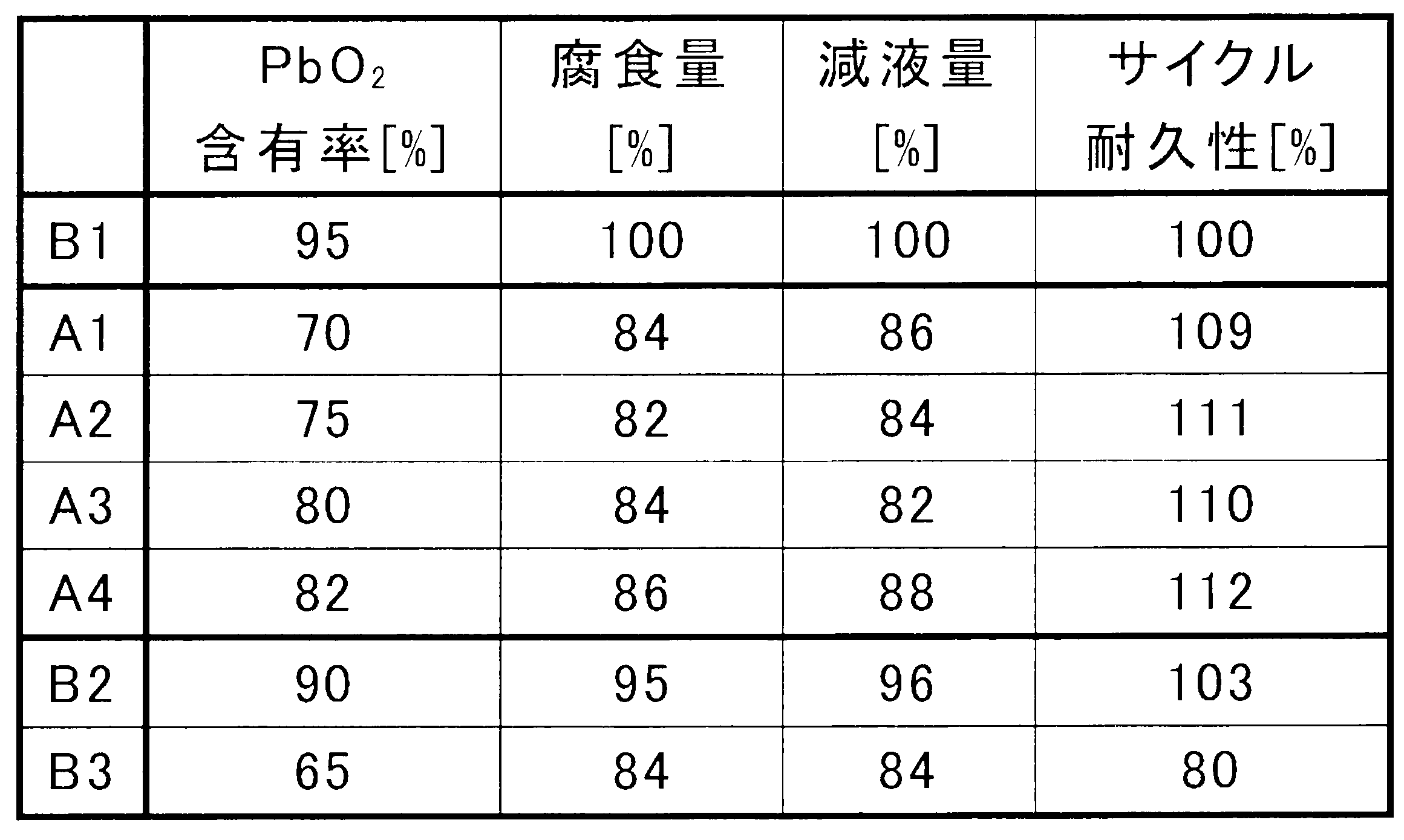
負極の作製において、表4に示す有機防縮剤と添加剤を用いたこと以外、鉛蓄電池A3と同様に実施例5~8の鉛蓄電池A5~A8を作製し、評価を実施する。既述の手順で求められる負極電極材料中の有機防縮剤の含有率は0.1質量%、添加剤(有機ポリマー化合物もしくは脂肪酸)の含有率は500ppmとする。表4中、PPGとは、ポリプロピレングリコールであり、数平均分子量Mnは1500であり、PPGの1H-NMRスペクトルでは、3.2~3.8ppmのケミカルシフトの範囲にピークが観察される。各電池の結果を、鉛蓄電池B1の結果の数値を100%としたときの相対値(%)で表4に示す。
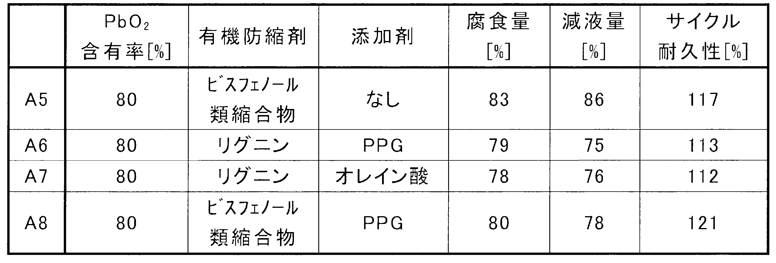
正極の作製において、既述の手順で求められる正極電極材料中のアンチモンの含有率が0.05質量%となるように、正極ペーストに三酸化アンチモンを添加する。また、正極集電体であるPb-Ca-Sn合金製のエキスパンド格子のSnの含有率を1.3質量%とする。また、負極の作製において、既述の手順で求められる負極電極材料中のカーボンブラックの含有率を1.3質量%とする。また、極板群の断面積に対する、極板群の外縁よりも外側に存在する電解液の断面積の比率Ra(極板群の投影平面への正投影像の面積に対する極板群の正投影像の外縁よりも外側に存在する電解液の投影平面への正投影像の面積の比率RL/G)を0.13とし、電槽の内縁で囲まれた領域の面積に対する、正極の断面積の比率Rb(電解液の投影平面への正投影像の外縁で囲まれた領域の面積に対する正極の投影平面への正投影像の面積の比率RP/L)を0.36とする。上記以外、鉛蓄電池A3と同様に実施例9の鉛蓄電池A9を作製し、評価を実施する。結果を、鉛蓄電池B1の結果の数値を100%としたときの相対値(%)で表5に示す。
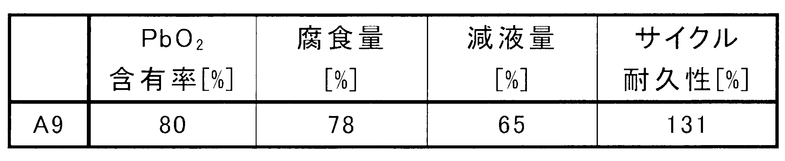
2:正極板
2a:耳部
3:負極板
3a:耳部
4:セパレータ
5:負極棚部
6:正極棚部
7:負極柱
8:貫通接続体
9:正極柱
11:極板群
12:電槽
13:隔壁
14:セル室
15:蓋
16:正極端子
17:負極端子
18:液口栓
Claims (20)
- 正極と、負極と、電解液と、を備え、
前記正極は、正極集電体と、正極電極材料と、を含み、
前記負極は、負極集電体と、負極電極材料と、を含み、
前記正極電極材料は、二酸化鉛を含み、
前記電解液は、水と、硫酸と、を含み、
前記鉛蓄電池が満充電状態であると仮定したときの仮想満充電状態において、前記正極電極材料中の二酸化鉛の含有率が、70質量%以上、82質量%以下である、鉛蓄電池。 - 前記仮想満充電状態は、前記電解液の比重が基準値の状態である、請求項1に記載の鉛蓄電池。
- 前記基準値の比重は、20℃において1.28である、請求項2に記載の鉛蓄電池。
- 前記鉛蓄電池の充電状態がX(%)であるとき、X(%)=100×W2/W4で表され、
W2は、前記電解液中の実測硫酸量(g)、
W4は、前記電解液の比重が前記基準値のときの前記電解液中の硫酸量(g)である、請求項1~3のいずれか1項に記載の鉛蓄電池。 - PSOCで使用される、請求項1~3のいずれか1項に記載の鉛蓄電池。
- アイドリングストップ制御される車両に搭載される、請求項5に記載の鉛蓄電池。
- 前記負極電極材料中に合成有機防縮剤を含む、請求項1~3のいずれか1項に記載の鉛蓄電池。
- 前記負極電極材料が、有機ポリマー化合物および脂肪酸からなる群より選択される少なくとも1種を含む、請求項1~3のいずれか1項に記載の鉛蓄電池。
- 前記有機ポリマー化合物は、オキシC2-4アルキレンユニットの繰り返し構造を有する、請求項1~3のいずれか1項に記載の鉛蓄電池。
- 前記負極電極材料は、炭素質材料を含み、
前記負極電極材料中の前記炭素質材料の含有率が、0.45質量%以上である、請求項1~3のいずれか1項に記載の鉛蓄電池。 - 前記正極電極材料は、アンチモンを含み、
前記正極電極材料中の前記アンチモンの含有率が、0.03質量%以上である、請求項1~3のいずれか1項に記載の鉛蓄電池。 - 前記正極集電体は、錫を含み、
前記正極集電体中の前記錫の含有率が、0.95質量%以上である、請求項1~3のいずれか1項に記載の鉛蓄電池。 - 前記鉛蓄電池は、極板群と前記電解液とを収容する電槽を備え、
前記極板群は、前記正極と前記負極と前記正極と前記負極との間に介在するセパレータとを含み、
前記鉛蓄電池の前記電槽の底部と平行な断面において、
前記極板群の断面積に対する、前記極板群の外縁よりも外側に存在する前記電解液の断面積の比率Raが、0.2以下である、請求項1~3のいずれか1項に記載の鉛蓄電池。 - 前記電槽の内縁で囲まれた領域の面積に対する、前記正極の断面積の比率Rbが、0.3以上である、請求項13に記載の鉛蓄電池。
- 水素の酸化による水の生成反応を促進する触媒を含み、生成した水を前記電解液に戻す触媒部を有する、請求項1~3のいずれか1項に記載の鉛蓄電池。
- 正極と、負極と、電解液と、を備える未化成のセルを組み立てる工程と、
前記未化成のセルを化成する工程と、
を具備し、
前記正極は、正極集電体と、ペースト式の正極電極材料と、を含み、
前記正極電極材料は、二酸化鉛を含み、
前記電解液は、水と、硫酸と、を含み、
前記化成後の前記正極電極材料中の二酸化鉛の含有率が、70質量%以上、82質量%以下である、鉛蓄電池の製造方法。 - 前記化成後の前記電解液の比重が基準値の状態でないときは、前記電解液の比重を基準値に調整する工程を更に有する、請求項16に記載の鉛蓄電池の製造方法。
- 請求項1に記載の鉛蓄電池の使用方法であって、
アイドリングストップ制御される車両に搭載された前記鉛蓄電池をPSOCで充放電する工程を有する、使用方法。 - 前記鉛蓄電池が満充電状態であると仮定したときの仮想満充電状態において、前記正極電極材料中の二酸化鉛の含有率が、70質量%以上、80質量%未満である、請求項1~3のいずれか1項に記載の鉛蓄電池。
- 前記鉛蓄電池が満充電状態であると仮定したときの仮想満充電状態において、前記正極電極材料中の二酸化鉛の含有率が、70質量%以上、75質量%以下である、請求項1~3のいずれか1項に記載の鉛蓄電池。
Priority Applications (2)
| Application Number | Priority Date | Filing Date | Title |
|---|---|---|---|
| EP23796255.0A EP4496068A4 (en) | 2022-04-26 | 2023-04-21 | LEAD-ACID BATTERY AND ITS PROCESS OF MANUFACTURE, AND ASSOCIATED METHOD OF USE |
| JP2024517270A JPWO2023210513A1 (ja) | 2022-04-26 | 2023-04-21 |
Applications Claiming Priority (2)
| Application Number | Priority Date | Filing Date | Title |
|---|---|---|---|
| JP2022072544 | 2022-04-26 | ||
| JP2022-072544 | 2022-04-26 |
Publications (1)
| Publication Number | Publication Date |
|---|---|
| WO2023210513A1 true WO2023210513A1 (ja) | 2023-11-02 |
Family
ID=88518721
Family Applications (1)
| Application Number | Title | Priority Date | Filing Date |
|---|---|---|---|
| PCT/JP2023/015844 Ceased WO2023210513A1 (ja) | 2022-04-26 | 2023-04-21 | 鉛蓄電池およびその製造方法、および使用方法 |
Country Status (4)
| Country | Link |
|---|---|
| EP (1) | EP4496068A4 (ja) |
| JP (1) | JPWO2023210513A1 (ja) |
| TW (1) | TW202401879A (ja) |
| WO (1) | WO2023210513A1 (ja) |
Cited By (3)
| Publication number | Priority date | Publication date | Assignee | Title |
|---|---|---|---|---|
| WO2025047743A1 (ja) * | 2023-08-31 | 2025-03-06 | 株式会社Gsユアサ | 鉛蓄電池 |
| WO2025053154A1 (ja) * | 2023-09-08 | 2025-03-13 | 株式会社Gsユアサ | 液式鉛蓄電池 |
| CN120357051A (zh) * | 2025-06-09 | 2025-07-22 | 杭州华宇新能源研究院有限公司 | 一种薄极板的铅酸蓄电池 |
Citations (8)
| Publication number | Priority date | Publication date | Assignee | Title |
|---|---|---|---|---|
| JPH10208746A (ja) | 1997-01-20 | 1998-08-07 | Japan Storage Battery Co Ltd | 密閉形鉛蓄電池 |
| JP2004171983A (ja) | 2002-11-21 | 2004-06-17 | Japan Storage Battery Co Ltd | 鉛蓄電池の製造、保存および補充電方法 |
| JP2018018803A (ja) * | 2016-07-29 | 2018-02-01 | 株式会社Gsユアサ | 鉛蓄電池 |
| WO2018155422A1 (ja) | 2017-02-23 | 2018-08-30 | 独立行政法人国立高等専門学校機構 | 鉛蓄電池用正極及びそれを用いた鉛蓄電池 |
| WO2019077657A1 (ja) | 2017-10-16 | 2019-04-25 | 日立化成株式会社 | 鉛蓄電池、アイドリングストップ車及びマイクロハイブリッド車 |
| JP2020102359A (ja) | 2018-12-21 | 2020-07-02 | 株式会社Gsユアサ | 鉛蓄電池 |
| JP2021099920A (ja) * | 2019-12-20 | 2021-07-01 | 株式会社Gsユアサ | 鉛蓄電池 |
| JP2022009931A (ja) * | 2016-07-29 | 2022-01-14 | 株式会社Gsユアサ | 鉛蓄電池 |
Family Cites Families (6)
| Publication number | Priority date | Publication date | Assignee | Title |
|---|---|---|---|---|
| US5149606A (en) * | 1991-03-12 | 1992-09-22 | Globe-Union Inc. | Method of treating a battery electrode with persulfate |
| JPH0513074A (ja) * | 1991-06-27 | 1993-01-22 | Japan Storage Battery Co Ltd | 鉛蓄電池用ペースト式正極板の製造方法 |
| JP2008311051A (ja) * | 2007-06-14 | 2008-12-25 | Gs Yuasa Corporation:Kk | 鉛蓄電池 |
| CN113906595A (zh) * | 2019-05-31 | 2022-01-07 | 株式会社杰士汤浅国际 | 铅蓄电池 |
| JP7173322B2 (ja) * | 2019-05-31 | 2022-11-16 | 株式会社Gsユアサ | 鉛蓄電池 |
| KR20220040890A (ko) * | 2020-09-24 | 2022-03-31 | 한국앤컴퍼니 주식회사 | 다공성 산소 및 수소 재결합 촉매바를 포함하고 있는 납축전지 및 이의 제조 방법 |
-
2023
- 2023-04-21 WO PCT/JP2023/015844 patent/WO2023210513A1/ja not_active Ceased
- 2023-04-21 EP EP23796255.0A patent/EP4496068A4/en active Pending
- 2023-04-21 JP JP2024517270A patent/JPWO2023210513A1/ja active Pending
- 2023-04-25 TW TW112115237A patent/TW202401879A/zh unknown
Patent Citations (8)
| Publication number | Priority date | Publication date | Assignee | Title |
|---|---|---|---|---|
| JPH10208746A (ja) | 1997-01-20 | 1998-08-07 | Japan Storage Battery Co Ltd | 密閉形鉛蓄電池 |
| JP2004171983A (ja) | 2002-11-21 | 2004-06-17 | Japan Storage Battery Co Ltd | 鉛蓄電池の製造、保存および補充電方法 |
| JP2018018803A (ja) * | 2016-07-29 | 2018-02-01 | 株式会社Gsユアサ | 鉛蓄電池 |
| JP2022009931A (ja) * | 2016-07-29 | 2022-01-14 | 株式会社Gsユアサ | 鉛蓄電池 |
| WO2018155422A1 (ja) | 2017-02-23 | 2018-08-30 | 独立行政法人国立高等専門学校機構 | 鉛蓄電池用正極及びそれを用いた鉛蓄電池 |
| WO2019077657A1 (ja) | 2017-10-16 | 2019-04-25 | 日立化成株式会社 | 鉛蓄電池、アイドリングストップ車及びマイクロハイブリッド車 |
| JP2020102359A (ja) | 2018-12-21 | 2020-07-02 | 株式会社Gsユアサ | 鉛蓄電池 |
| JP2021099920A (ja) * | 2019-12-20 | 2021-07-01 | 株式会社Gsユアサ | 鉛蓄電池 |
Non-Patent Citations (2)
| Title |
|---|
| See also references of EP4496068A4 |
| THE SULPHURIC ACID ASSOCIATION OF JAPAN: "Sulfuric Acid Handbook", 12 December 2012 |
Cited By (3)
| Publication number | Priority date | Publication date | Assignee | Title |
|---|---|---|---|---|
| WO2025047743A1 (ja) * | 2023-08-31 | 2025-03-06 | 株式会社Gsユアサ | 鉛蓄電池 |
| WO2025053154A1 (ja) * | 2023-09-08 | 2025-03-13 | 株式会社Gsユアサ | 液式鉛蓄電池 |
| CN120357051A (zh) * | 2025-06-09 | 2025-07-22 | 杭州华宇新能源研究院有限公司 | 一种薄极板的铅酸蓄电池 |
Also Published As
| Publication number | Publication date |
|---|---|
| EP4496068A1 (en) | 2025-01-22 |
| EP4496068A4 (en) | 2025-12-10 |
| JPWO2023210513A1 (ja) | 2023-11-02 |
| TW202401879A (zh) | 2024-01-01 |
Similar Documents
| Publication | Publication Date | Title |
|---|---|---|
| WO2023210513A1 (ja) | 鉛蓄電池およびその製造方法、および使用方法 | |
| KR20140021663A (ko) | 납축전지 | |
| JP7255492B2 (ja) | 鉛蓄電池 | |
| JP7355005B6 (ja) | 鉛蓄電池 | |
| JP7124828B2 (ja) | 鉛蓄電池 | |
| JP7375457B2 (ja) | 鉛蓄電池 | |
| JP7259758B2 (ja) | 鉛蓄電池 | |
| JP6954353B2 (ja) | 鉛蓄電池 | |
| JP7363288B2 (ja) | 鉛蓄電池用負極板および鉛蓄電池、ならびに鉛蓄電池用負極板の製造方法 | |
| JP7147777B2 (ja) | 鉛蓄電池 | |
| JP7147776B2 (ja) | 鉛蓄電池 | |
| JP7661978B2 (ja) | 鉛蓄電池 | |
| JP2024104758A (ja) | 鉛蓄電池 | |
| WO2023210635A1 (ja) | 鉛蓄電池 | |
| JP7797970B2 (ja) | 鉛蓄電池 | |
| EP4525129A1 (en) | Lead-acid battery | |
| JP7694585B2 (ja) | 鉛蓄電池用クラッド式正極板および鉛蓄電池 | |
| JP7754108B2 (ja) | 鉛蓄電池 | |
| WO2019225161A1 (ja) | 鉛蓄電池 | |
| JP2024029809A (ja) | 鉛蓄電池 | |
| JP2024029810A (ja) | 鉛蓄電池 | |
| JP7476510B2 (ja) | 鉛蓄電池 | |
| WO2025047743A1 (ja) | 鉛蓄電池 | |
| WO2025053154A1 (ja) | 液式鉛蓄電池 | |
| WO2023210636A1 (ja) | 鉛蓄電池 |
Legal Events
| Date | Code | Title | Description |
|---|---|---|---|
| 121 | Ep: the epo has been informed by wipo that ep was designated in this application |
Ref document number: 23796255 Country of ref document: EP Kind code of ref document: A1 |
|
| WWE | Wipo information: entry into national phase |
Ref document number: 2024517270 Country of ref document: JP |
|
| WWE | Wipo information: entry into national phase |
Ref document number: 2023796255 Country of ref document: EP |
|
| ENP | Entry into the national phase |
Ref document number: 2023796255 Country of ref document: EP Effective date: 20241014 |
|
| WWE | Wipo information: entry into national phase |
Ref document number: 2401007056 Country of ref document: TH |
|
| NENP | Non-entry into the national phase |
Ref country code: DE |