WO2023210825A1 - 鉄道アップサイクルシステム、その方法及びそれによる生産方法 - Google Patents
鉄道アップサイクルシステム、その方法及びそれによる生産方法 Download PDFInfo
- Publication number
- WO2023210825A1 WO2023210825A1 PCT/JP2023/016960 JP2023016960W WO2023210825A1 WO 2023210825 A1 WO2023210825 A1 WO 2023210825A1 JP 2023016960 W JP2023016960 W JP 2023016960W WO 2023210825 A1 WO2023210825 A1 WO 2023210825A1
- Authority
- WO
- WIPO (PCT)
- Prior art keywords
- railway
- upcycling
- storage battery
- digital twin
- vehicle
- Prior art date
- Legal status (The legal status is an assumption and is not a legal conclusion. Google has not performed a legal analysis and makes no representation as to the accuracy of the status listed.)
- Ceased
Links
Images









Classifications
-
- G—PHYSICS
- G06—COMPUTING OR CALCULATING; COUNTING
- G06Q—INFORMATION AND COMMUNICATION TECHNOLOGY [ICT] SPECIALLY ADAPTED FOR ADMINISTRATIVE, COMMERCIAL, FINANCIAL, MANAGERIAL OR SUPERVISORY PURPOSES; SYSTEMS OR METHODS SPECIALLY ADAPTED FOR ADMINISTRATIVE, COMMERCIAL, FINANCIAL, MANAGERIAL OR SUPERVISORY PURPOSES, NOT OTHERWISE PROVIDED FOR
- G06Q10/00—Administration; Management
- G06Q10/06—Resources, workflows, human or project management; Enterprise or organisation planning; Enterprise or organisation modelling
-
- B—PERFORMING OPERATIONS; TRANSPORTING
- B61—RAILWAYS
- B61L—GUIDING RAILWAY TRAFFIC; ENSURING THE SAFETY OF RAILWAY TRAFFIC
- B61L27/00—Central railway traffic control systems; Trackside control; Communication systems specially adapted therefor
- B61L27/60—Testing or simulation
-
- B—PERFORMING OPERATIONS; TRANSPORTING
- B61—RAILWAYS
- B61L—GUIDING RAILWAY TRAFFIC; ENSURING THE SAFETY OF RAILWAY TRAFFIC
- B61L27/00—Central railway traffic control systems; Trackside control; Communication systems specially adapted therefor
- B61L27/50—Trackside diagnosis or maintenance, e.g. software upgrades
- B61L27/57—Trackside diagnosis or maintenance, e.g. software upgrades for vehicles or trains, e.g. trackside supervision of train conditions
-
- G—PHYSICS
- G06—COMPUTING OR CALCULATING; COUNTING
- G06Q—INFORMATION AND COMMUNICATION TECHNOLOGY [ICT] SPECIALLY ADAPTED FOR ADMINISTRATIVE, COMMERCIAL, FINANCIAL, MANAGERIAL OR SUPERVISORY PURPOSES; SYSTEMS OR METHODS SPECIALLY ADAPTED FOR ADMINISTRATIVE, COMMERCIAL, FINANCIAL, MANAGERIAL OR SUPERVISORY PURPOSES, NOT OTHERWISE PROVIDED FOR
- G06Q10/00—Administration; Management
- G06Q10/20—Administration of product repair or maintenance
-
- G—PHYSICS
- G06—COMPUTING OR CALCULATING; COUNTING
- G06Q—INFORMATION AND COMMUNICATION TECHNOLOGY [ICT] SPECIALLY ADAPTED FOR ADMINISTRATIVE, COMMERCIAL, FINANCIAL, MANAGERIAL OR SUPERVISORY PURPOSES; SYSTEMS OR METHODS SPECIALLY ADAPTED FOR ADMINISTRATIVE, COMMERCIAL, FINANCIAL, MANAGERIAL OR SUPERVISORY PURPOSES, NOT OTHERWISE PROVIDED FOR
- G06Q10/00—Administration; Management
- G06Q10/30—Administration of product recycling or disposal
-
- G—PHYSICS
- G06—COMPUTING OR CALCULATING; COUNTING
- G06Q—INFORMATION AND COMMUNICATION TECHNOLOGY [ICT] SPECIALLY ADAPTED FOR ADMINISTRATIVE, COMMERCIAL, FINANCIAL, MANAGERIAL OR SUPERVISORY PURPOSES; SYSTEMS OR METHODS SPECIALLY ADAPTED FOR ADMINISTRATIVE, COMMERCIAL, FINANCIAL, MANAGERIAL OR SUPERVISORY PURPOSES, NOT OTHERWISE PROVIDED FOR
- G06Q50/00—Information and communication technology [ICT] specially adapted for implementation of business processes of specific business sectors, e.g. utilities or tourism
- G06Q50/40—Business processes related to the transportation industry
-
- B—PERFORMING OPERATIONS; TRANSPORTING
- B60—VEHICLES IN GENERAL
- B60L—PROPULSION OF ELECTRICALLY-PROPELLED VEHICLES; SUPPLYING ELECTRIC POWER FOR AUXILIARY EQUIPMENT OF ELECTRICALLY-PROPELLED VEHICLES; ELECTRODYNAMIC BRAKE SYSTEMS FOR VEHICLES IN GENERAL; MAGNETIC SUSPENSION OR LEVITATION FOR VEHICLES; MONITORING OPERATING VARIABLES OF ELECTRICALLY-PROPELLED VEHICLES; ELECTRIC SAFETY DEVICES FOR ELECTRICALLY-PROPELLED VEHICLES
- B60L2200/00—Type of vehicles
- B60L2200/26—Rail vehicles
Definitions
- the present invention relates to a railway upcycling system, a method thereof, and a production method using the same.
- target products target products
- target products target products
- a technology that improves the value of products, etc. in this way.
- value can be classified into environmental value, economic value, and social value.
- environmental values include low energy consumption, low noise, and low vibration for railway systems.
- economic values for railway systems include small size, light weight, safety, ease of use from a user's perspective, and ease of access.
- Social value is considered to be a goal that should be aimed at along with the realization of environmental value and economic value, and is known as SDGs (Sustainable Development Goals).
- Patent Document 1 discloses that field performance data of vehicle subsystems monitored by sensors mounted on the vehicle during operation is acquired, and the vehicle performance is determined based on the variance between the simulated performance data and the field performance data.
- a system for determining the performance composite index of subsystems is described. Controlling a vehicle during or after its operation based on a performance composite index and automatically scheduling preventive maintenance of a vehicle based on a health score are described.
- Non-Patent Document 1 describes the Taguchi method (in order to eliminate various quality variations that occur in product manufacturing, accept those variations at the design stage and prevent variations in the actual product functions) for designing parameters for adhesion control.
- the paper describes robust adhesion control that appropriately follows the ever-changing adhesion state by applying the framework of the stabilization design method.
- the purpose of the present invention is to make it possible to accurately judge whether or not to upcycle, thereby improving the performance of upcycled equipment, software, etc. related to railway systems compared to conventional specifications.
- the objective is to provide a railway upcycling system that can repeatedly improve performance.
- the present invention for solving the above problems includes a controller and a memory, the controller and the memory construct a digital twin environment that simulates a railway system, and improve the value of the railway system according to a program in the memory.
- the controller sets a first digital twin model that simulates an object that belongs to the railway system and whose value is to be improved, and adjusts parameters of the first digital twin model by incorporating operational data of the object. , improve the accuracy of the first digital twin model, set a second digital twin model that simulates the updated target when the value of the target is improved, and compare the first digital twin model and the second digital twin model under the same conditions. By comparing the simulation results of each operation, it is possible to evaluate the value improvement.
- the present invention by making an accurate judgment as to whether or not to upcycle, it is possible to improve the performance of upcycled equipment, software, etc. related to railway systems compared to conventional specifications, and further improve such performance.
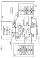
- FIG. 1 is a configuration diagram showing a concept of parallel analysis in a railway upcycling system (hereinafter also referred to as "this upcycling system") according to Example 1 of the present invention.
- FIG. 2 is a functional configuration diagram showing the basic operation of the present upcycling system of FIG. 1.
- FIG. 2 is a functional configuration diagram showing an example of the basic operation (simulated vehicle model update) of the present upcycling system shown in FIG. 1.
- FIG. FIG. 2 is a functional configuration diagram showing an example of the basic operation (actual vehicle control update) of the present upcycling system shown in FIG. 1.
- FIG. FIG. 2 is a schematic explanatory diagram showing an example of the information transmission section 3 of the present upcycling system of FIG. 1.
- FIG. 7 is a schematic explanatory diagram for explaining parameter identification in the circulation system of FIG. 6.
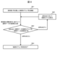
- FIG. 8 is a flowchart for explaining the parameter identification procedure of FIG. 7.
- FIG. 7 is a schematic explanatory diagram for explaining upcycle evaluation in the circulation system of FIG. 6.
- FIG. 10 is a flowchart for explaining the upcycle evaluation procedure of FIG. 9.
- 7 is a schematic explanatory diagram for explaining parameter identification (after upcycling) in the circulation system of FIG. 6.
- FIG. 12 is a flowchart for explaining the procedure of parameter identification (after upcycle) in FIG. 11.
- FIG. 7 is a schematic explanatory diagram for explaining maintenance judgment in the circulation system of FIG. 6.
- FIG. 14 is a flowchart for explaining the maintenance determination procedure of FIG. 13.
- FIG. FIG. 2 is a conceptual explanatory diagram for explaining a maintenance plan proposal function in addition to a product and material data management function in this upcycling system.
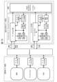
- 6 is a functional block diagram showing the configuration of a modification in which the actual vehicles 11a and 11b of FIG. 5 are connected into one formation.
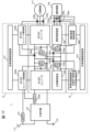
- FIG. FIG. 17 is a functional block diagram showing the configuration of the actual vehicle 11a of FIG. 16 in more detail.
- 2 is a diagram showing an example of an ID system that defines traceability of hardware/software of the parallel analysis system of FIG. 1.
- FIG. 7 is a conceptual explanatory diagram for explaining a storage battery circulation system using the upcycle system of Example 3.
- 6 is a schematic explanatory diagram showing another example of the information transmission section 3 shown in FIG. 5.
- FIG. 18 is a block diagram showing the configuration of the drive system of the actual vehicle 11 when the main circuit storage battery 123 of FIG. 17 is composed of a plurality of storage battery systems.
- FIG. 1 is a diagram showing the internal configuration of a storage battery system.
- (a) is a diagram showing the configuration of a controller that collects data from the storage battery system.
- (b) is a diagram showing necessary data required as quality data of a storage battery.
- FIG. 7 is a diagram illustrating an example of an ID system that enables traceability in Embodiment 3.
- FIG. 7 is a diagram illustrating an example of an ID system that enables traceability in Embodiment 3.
- FIG. 3 is a step diagram showing a maintenance/replacement process of the storage battery system.
- FIG. 2 is a flow diagram showing a maintenance and replacement process for the storage battery system.
- FIG. 2 is a diagram showing the configuration of a model (simulation model) that simulates charging and discharging operations of a storage battery system.
- FIGS. 1 to 5 A first embodiment mainly related to software will be described using FIGS. 1 to 5, and a second embodiment mainly related to hardware (things) will be described using FIGS. 6 to 18.
- parts having the same effect are given the same reference numerals throughout each figure to avoid duplication of explanation.
- FIG. 6 the relationship between each requirement is also clearly indicated in the diagram based on the words and phrases described, so the reference numerals are omitted.
- the reference numerals are omitted in FIGS. 9, 11, 13, 15, and 18.
- the railway upcycle includes a controller and a memory, the controller and the memory construct a digital twin environment that simulates a railway system, and improves the value of the railway system according to the program in the memory.
- a system or railway upcycling method wherein the controller sets a first digital twin model that simulates a value-enhancing target belonging to the railway system, and adjusts the parameters of the first digital twin model by capturing operational data of the target. Adjust the accuracy of the first digital twin model, set a second digital twin model that simulates the updated target when the value of the target is improved, and set the first digital twin model and the second digital twin model under the same conditions.
- a common ID is given to an object belonging to a railway system and a digital twin model corresponding thereto, and operational data is linked to the ID.
- the embodiment explains that the operational data used to adjust the parameters of the digital twin model includes train operation information, driving instructions or operations, train configuration information, or vehicle equipment operation. .
- the operational data used to adjust the parameters of the digital twin model includes frequency, input/output current/voltage, or power unit temperature if the target is a drive control device, and if the target is a drive control device, the operational data includes frequency, input/output current/voltage, or power unit temperature. Then, frequency, input/output current/voltage, or power unit temperature is included; if the target is a storage battery, charging/discharging current, voltage, SOC, SOH, or temperature is included; if the target is a train information control device, each It will be explained that the equipment status, occupancy rate, or room temperature is included, and if the target is a vehicle member, vibration, temperature, or distortion is included.
- the parameters of the digital twin model are adjusted after determining that the operational data of the target belonging to the railway system does not include abnormal data due to an accident or failure.
- the performance deterioration is grasped through a time calendar-based simulation, the performance deterioration timing is predicted, and the value improvement period is determined and proposed before the deterioration of the target belonging to the railway system begins.
- data on automatic driving or driving using a driving support system is used as operational data for objects belonging to the railway system.
- a driving pattern necessary for adjusting the digital twin model is defined in at least one of the driving pattern for automatic driving and the driving pattern for the driving support system.
- the objects whose value is improved include actual vehicles, storage batteries, drive control devices, auxiliary power supply control devices, fuel cell systems, air conditioners, in-vehicle monitoring devices, train information control devices, passenger information providing devices, seats, and vehicle Explain that it is any one of a component, a forward monitoring device, a safety monitoring device, a driving support system, an automatic driving control function, or a ground/onboard wireless information transmission control function.
- an ID used for individual recognition is assigned to an object belonging to the railway system, a medical record is linked to the ID, and the medical record is updated with the same work implementation content as the changed work data.
- parameters of control software are automatically adjusted on the digital twin model based on operational data, and the automatically adjusted software is activated in response to a predetermined trigger.
- the automatically adjusted parameters of the control software include adhesion control, forward monitoring sensitivity, driving support system pattern, automatic train control pattern, hybrid energy management, storage battery current limit, storage battery SOC range limit, tension control by acceleration limit, It will be explained that this is blending control or equipment operation changeover point information.
- control software for train drive systems is exemplified as a subject of upcycling related to railways, but it also includes control software for onboard equipment such as traffic management systems, vehicle information control systems, and automatic driving systems.
- Example 1 illustrates a parallel analysis system (see FIG. 1) that predicts the operation of a railway vehicle drive control system and optimizes control.
- this upcycling system will be exemplified, which verifies the benefits and disadvantages of updating the software that implements the railway vehicle drive control system, and supports the decision on whether to update (upcycle).
- this upcycling system uses a digital twin that simulates the conditions of an actual vehicle in real space to maintain the drive control of a railway vehicle in an optimal state that corresponds to route conditions, riding conditions, and weather conditions. If it is determined that upcycling is effective, it will be carried out.
- the search for the stability control parameters is preferably performed in a simulation environment or the like that provides an environment as close to the actual vehicle 11 as possible.
- the railway vehicle drive control system drives the train by controlling the torque of the main electric motor 117 mounted on the electric vehicle among the electric vehicles and accompanying vehicles that make up the train, using a main conversion device installed on the same vehicle or an adjacent vehicle. .
- Torque control of the traction motor 117 is performed based on the mechanical characteristics of the traction motor 117, equipment specifications such as drive system specifications (wheel diameter, gear ratio, etc.), vehicle specifications (vehicle mass, running resistance, load, etc.), and vehicle Generally, functions are designed based on specifications to satisfy predetermined vehicle performance, such as acceleration characteristics and deceleration characteristics, and are realized by software installed in the controller of the main conversion device.
- the software of the main conversion device that realizes vehicle performance is functionally designed based on the equipment and vehicle specifications.
- the vehicle performance achieved by the designed software is finally confirmed through a running test on the actual vehicle 11 to ensure that it satisfies a predetermined performance.
- the vehicle performance designed based on the ideal equipment specifications and vehicle specifications differs from the actual vehicle 11. Therefore, it is necessary to recognize the difference between the two through a running test on the actual vehicle 11, and then adjust the control to achieve a predetermined performance.
- driving performance such as acceleration and deceleration (including evaluation in rainy weather (wet rail surface)) is important.
- control adjustment in the actual vehicle 11 is required because the difference between the designed value and the actual measured value of the traction motor characteristic constant affects stability.
- control adjustment in the actual vehicle 11 is "robust adhesion control" described in Non-Patent Document 1. This "robust adhesion control” reduces the tread force that occurs when the tread force transmitted from the wheels to the rails based on motor torque exceeds the friction limit between the wheels and the rails, such as during rainy weather, by lowering the tread force. Adhesion control is disclosed.
- This adhesion control uses the Taguchi method to search for stable control parameters that stably transmit tread force against fluctuations in the friction limit due to rain conditions, etc., and performs performance verification using an actual vehicle 11 to which the stability control parameters are applied. .
- acceleration is distinguished from idling
- deceleration is distinguished from gliding, but here they are collectively referred to as ⁇ idling.''
- FIG. 1 is a configuration diagram showing the concept of parallel analysis in this upcycling system.
- the actual vehicle field 1 is an environment that is equipped with the equipment necessary for the actual vehicle 11 to run, and includes at least the actual vehicle 11 as well as rails 15 such as railways (not shown in Figures 5 and 6). ). Further, in the case where the actual vehicle 11 is an electric vehicle that runs by receiving power from outside the vehicle, it is provided with a power supply section 16 (FIGS. 5 and 6) that supplies power to the vehicle 11, such as an overhead wire or a third rail.
- the actual vehicle 11 is equipped with an actual vehicle drive section 12 configured with an electric motor, an inverter device, etc. that drives itself.
- the actual vehicle drive unit 12 may be provided with a power storage unit that temporarily stores regenerative power generated by the electric motor during braking or power generated by a fuel cell, engine, etc., and supplies it to the electric motor in a timely manner to obtain driving force. .
- the actual vehicle control unit 13 monitors the state of each part that constitutes the aforementioned actual vehicle 11 and controls the operation thereof.
- the actual vehicle drive unit 12 and the actual vehicle drive control unit 14 are provided with an interface for mutually transmitting and receiving information necessary for drive control.
- the actual vehicle drive control unit 14 outputs a PWM signal Vp that turns on/off a switching circuit of an inverter device that constitutes the actual vehicle drive unit 12.
- the actual vehicle drive unit 12 outputs at least a motor current Im flowing through the electric motor and an input voltage Ecf of the switching circuit, and inputs the output to the simulated vehicle drive control unit 24. do.
- the simulated vehicle field 2 is an environment equipped with the equipment necessary for the running of the simulated vehicle 21, and includes at least the simulated vehicle 21 and rails 15 such as railroad tracks (FIGS. 5 and 6). Further, in the case where the simulated vehicle 21 is an electric vehicle that receives electric power supplied from outside the vehicle and runs, it is provided with a power supply section 16 (FIGS. 5 and 6) that supplies electric power to the vehicle 11, such as an overhead wire or a third rail. In this way, in the simulated vehicle field 2, the real vehicle 11 in the real vehicle field 1 is replaced with the simulated vehicle 21. Similarly, the real vehicle drive section 12 is replaced with a simulated vehicle drive section 22, the real vehicle control section 13 is replaced with a simulated vehicle control section 23, and the real vehicle drive control section 14 is replaced with a simulated vehicle drive control section 24.
- the simulated vehicle 21, the simulated vehicle drive unit 22, the simulated vehicle control unit 23, and the simulated vehicle drive control unit 24 that constitute the simulated vehicle field 2 are computer-based simulators.
- the vehicle drive unit 22 is the actual vehicle drive unit 12
- the simulated vehicle control unit 23 is the actual vehicle control unit 13
- the simulated vehicle drive control unit 24 is the actual vehicle drive control unit 14, and one or more of these units actually exist.
- a mixed configuration Hardware In the Loop Simulator
- the real vehicle field 1 and the simulated vehicle field 2 operate on the same time scale, but the absolute times at which they operate do not necessarily need to be the same.
- the simulated vehicle 21 includes a simulated vehicle drive unit 22 that includes an electric motor that drives itself, an inverter device, and the like.
- the simulated vehicle drive unit 22 may be provided with a power storage unit that temporarily stores regenerative power generated by the electric motor during braking or power generated by a fuel cell, engine, etc., and supplies it to the electric motor in a timely manner to obtain driving force. be.
- the simulated vehicle control unit 23 monitors the state of each part constituting the aforementioned simulated vehicle 21 and controls the operation thereof.
- the simulated vehicle drive unit 22 and the simulated vehicle drive control unit 24 are provided with an interface that mutually exchanges information necessary for drive control.
- the simulated vehicle drive control section 24 outputs a PWM signal Vp that turns on/off a switching circuit of an inverter device that constitutes the simulated vehicle drive section 22.
- the simulated vehicle drive unit 22 outputs at least a motor current Im flowing through the electric motor and an input voltage Ecf of the switching circuit, and inputs the output to the simulated vehicle drive control unit 24. do.
- the simulated vehicle field 2 includes all or a part of the real vehicle 11, the real vehicle drive section 12, the real vehicle control section 13, and the real vehicle drive control section 14 that constitute the real vehicle field 1 with the CPU and memory.
- the real vehicle field 1 and the simulated vehicle field 2 can run in parallel by replacing the simulator with a simulator realized by an electronic computer having a simulator and mutually receiving data.
- parallel running means that when the real vehicle field 1 and the simulated vehicle field 2 run based on the same driving command, running data such as vehicle acceleration, speed, mileage, current value of the vehicle drive unit, voltage This is a railway system control method that minimizes the difference between the two values.
- the status of each part constituting the real vehicle 11 in the real vehicle field 1 is transmitted to the simulated vehicle field 2 via the information transmission section 3.
- the simulated vehicle 21 constituting the simulated vehicle field 2 is defined as a physical theoretical model on a simulator realized by an electronic computer. However, in contrast to the simulated vehicle environment as a physical theoretical model, the actual vehicle environment has variable elements such as route conditions, riding conditions, and weather conditions.
- a vehicle motion analysis unit 231 (not shown) is provided to modify the physical theory model of the simulated vehicle 21 based on the analysis results.
- the driving data will be the same when the actual vehicle field 1 and the simulated vehicle field 2 travel based on the same driving command. That is, if the control operations of the simulated vehicle drive unit 22 and the simulated vehicle control unit 23 are stable in the simulated vehicle field 2, the control operations of the actual vehicle drive unit 12 and the actual vehicle control unit 13 are also stable in the simulated vehicle field 2. We can expect it to be. For this reason, first, the drive control operation data is corrected in the simulated vehicle field 2 so that the control operations of the simulated vehicle drive section 22 and the simulated vehicle control section 23 become stable.
- the simulated vehicle control unit 23 includes an adjustment calculation unit that changes the drive control operation data that realizes the control operation of the simulated vehicle drive control unit 24 and stabilizes the state of each part constituting the simulated vehicle 21. .
- the optimized drive control operation data is transmitted to the actual vehicle field 1 via the information transmission section 3 to update the drive control operation data already installed in the vehicle control section 13 or vehicle drive control section 14.
- the drive control operation data of the vehicle control unit 13 or the vehicle drive control unit 14 is automatically updated when a predetermined condition is satisfied, such as when the actual vehicle 11 in the actual vehicle field 1 is stopped or the operation of the vehicle drive control unit 14 is stopped.
- a predetermined condition such as when the actual vehicle 11 in the actual vehicle field 1 is stopped or the operation of the vehicle drive control unit 14 is stopped.
- the travel data of the real vehicle 11 operated according to the optimized drive control operation data of the real vehicle field 1 is transmitted to the simulated vehicle field 2 via the information transmission section 3.
- the drive control operation data of the simulated vehicle drive control unit 24 or the physical theory model of the simulated vehicle 21 is re-corrected in this manner.
- the simulator determines whether to modify the drive control operation data or the physical theory model based on the following criteria.
- the running data of the real vehicle 11 and the running data of the real vehicle 11 are compared to the running data of the real vehicle 11 when the real vehicle field 1 and the simulated vehicle field 2 run based on the same driving command.
- the difference in running data of the vehicle 11 is compared with the difference in running data of the actual vehicle 11 operated based on drive control operation data before and after optimization, and the following is executed.
- the drive control operation data is implemented in the actual vehicle drive control unit 14 to control the operation of the actual vehicle drive unit 12 or in the simulated vehicle drive control unit 24 to control the operation of the simulated vehicle drive unit 22.
- Control logic such as software, or configuration parameters of control logic to be implemented.
- the model accuracy of the simulator that constitutes the simulated vehicle field 2 can be improved based on the driving data of the actual vehicle field 1.
- the behavior when the drive control operation data is changed in the actual vehicle field 1 is changed to the operation when the drive control operation data is changed in the simulated vehicle field 2. It is possible to make predictions and pre-verify based on the results.
- the drive control operation data previously verified in the simulated vehicle field 2 is transmitted to the actual vehicle field 1 via the information transmission section 3, and the drive control operation data in the actual vehicle field 1 is changed to confirm the actual operation. can.
- the procedure is to improve the accuracy of the simulated vehicle 21 so that its movement is the same as that of the real vehicle 11, adjust the drive control in the simulated vehicle 21 with improved accuracy, and apply the adjusted drive control operation data to the real vehicle 11.
- FIG. 2 is a functional configuration diagram showing the basic operation of the present upcycling system of FIG. 1.
- an actual vehicle field 1 and a simulated vehicle field 2 are configured to be able to mutually transmit and receive information data through an information transmitter 3.
- the driving command unit 111 outputs a driving command COM that commands the operation of the actual vehicle 11, such as power running (acceleration), braking (deceleration/stopping), and off (coasting).
- the driving command COM is input to the actual vehicle drive control unit 14, and the driving force output by the actual vehicle driving unit 12 (not shown) is controlled so that the actual vehicle 11 operates according to the driving command COM. Further, the actual vehicle drive control unit 14 outputs state information STARr as a result of controlling the driving force output by the actual vehicle drive unit 12 so that the actual vehicle 11 operates according to the driving command COM.
- the state information STARr is physical quantity data recognized by software calculation of the actual vehicle drive control unit 14, and includes vehicle acceleration Acc, speed Vel, position Pos, rotational speed Fr of the main motor 117, current Im, voltage Vm, These include the DC current Is and DC voltage Ecf of the inverter device.
- the driving command COM and the state information STARr are input into the simulated vehicle field 2 via the information transmission section 3.
- the driving command COM is input to the simulated vehicle drive control unit 24 that constitutes the simulated vehicle 21, and controls the driving force output by the simulated vehicle driving unit 22 (not shown) so that the simulated vehicle 21 operates according to the driving command COM.
- the state information STARr particularly the speed data VELr and position data POSr of the actual vehicle 11 are input to the storage section (memory) 233.
- the storage unit 233 stores gradient data, curve data, station position data STN, etc. of the route on which the actual vehicle 11 travels.
- the slope data is table data that defines the slope amount (altitude increase rate relative to the travel distance) of the actual vehicle 11 at that position with respect to the travel position data POSr.
- the gradient data is table data that defines the curvature of the track (reciprocal of the curve radius) with respect to the traveling position data POSr of the actual vehicle 11.
- the station position data STN is table data indicating the positions of station facilities arranged on the running route with respect to the running position data POSr of the actual vehicle 11. Station facilities include stops, stops, signal stations, etc., and are usually expressed in kilometres, indicating the central location of each facility.
- the vehicle motion analysis unit 231 receives state information STAs output from the simulated vehicle 21 and state information STARr output from the actual vehicle 11 and transmitted to the simulated vehicle field 2 via the information transmission unit 3, and receives the state information STAs. Based on the state information STARr, a correction parameter ⁇ MDL of the simulated vehicle 21 that approximates the motion of the actual vehicle 11 and the motion of the simulated vehicle 21 is calculated. The correction parameter ⁇ MDL is input to the simulated vehicle 21 and corrects the configuration parameters of the simulated vehicle 21.
- the control data analysis unit 232 inputs the state information STAs, and analyzes and determines the optimal control parameter that most closely approximates the state information STAs and the state value STAp, which is the target control result.
- the state information STAs which is the result of the operation of the simulated vehicle 21 based on the driving command COM, follows the state information STARr, which is the result of the operation of the actual vehicle 11, which is also based on the driving command COM.
- This is done after the modification of the configuration parameters of the simulated vehicle 21 is completed.
- the simulated vehicle 21 and the simulated vehicle drive unit 22 after completion of configuration parameter modification exhibit the same behavior as the actual vehicle 11 and the actual vehicle drive unit 12 in response to the driving command COM, so the actual vehicle control unit 13 and the simulated vehicle control unit 23. If the control operations of the real vehicle drive control section 14 and the simulated vehicle drive control section 24 are made equal, the behavior of the real vehicle field 1 and the simulated vehicle field 2 will also be the same.
- the target It is possible to achieve the following control results.
- the transmission of the optimal control parameters from the simulated vehicle field 2 to the actual vehicle field 1 is realized by the information transmission section 3.
- the model accuracy of the simulator that constitutes the simulated vehicle field 2 can be improved based on the driving data of the actual vehicle field 1.
- the behavior when the drive control operation data is changed in the actual vehicle field 1 is changed to the operation when the drive control operation data is changed in the simulated vehicle field 2. It is possible to make predictions and pre-verify based on the results.
- the drive control operation data previously verified in the simulated vehicle field 2 is transmitted to the actual vehicle field 1 via the information transmission section 3, and the drive control operation data in the actual vehicle field 1 is changed to confirm the actual operation. can.
- the procedure is to improve the accuracy of the simulated vehicle 21 so that its movement is the same as that of the real vehicle 11, adjust the drive control in the simulated vehicle 21 with improved accuracy, and apply the adjusted drive control operation data to the real vehicle 11.
- the drive control operation data is implemented in the actual vehicle drive control unit 14 to control the operation of the actual vehicle drive unit 12 or in the simulated vehicle drive control unit 24 to control the operation of the simulated vehicle drive unit 22.
- Control logic such as software, or configuration parameters of control logic to be implemented.
- FIG. 3 is a functional configuration diagram showing an example of the basic operation (simulated vehicle model update) of the present upcycling system shown in FIG. 1.
- an actual vehicle field 1 and a simulated vehicle field 2 are configured to be able to mutually transmit and receive information data through an information transmitter 3.
- the driving command unit 111 outputs a driving command COM that commands the operation of the actual vehicle 11, such as power running (acceleration), braking (deceleration/stopping), and off (coasting). This includes the main controller operated by the driver and the ATO device in the case of automated driving.
- the driving command COM is input to the actual vehicle drive control unit 14, and the driving force output by the actual vehicle driving unit 12 (not shown) is controlled so that the actual vehicle 11 operates according to the driving command COM. Further, the actual vehicle drive control unit 14 outputs state information STARr as a result of controlling the driving force output by the actual vehicle drive unit 12 so that the actual vehicle 11 operates according to the driving command COM. Thereby, driving commands, position, and speed can be collected as actual vehicle data.
- the state information STARr is physical quantity data recognized by software calculation of the actual vehicle drive control unit 14, and includes vehicle acceleration Acc, speed Vel, position Pos, rotational speed Fr of the main motor 117, current Im, voltage Vm, These include the DC current Is and DC voltage Ecf of the inverter device.
- the driving command COM and the state information STARr are input into the simulated vehicle field 2 via the information transmission section 3.
- the storage unit 233 stores gradient data GRD, curve data CRV, station position data STN, etc. of the route on which the actual vehicle 11 travels.
- the slope data GRD is table data that defines the amount of slope (elevation increase rate relative to the travel distance) at a position relative to the travel position data POSr of the actual vehicle 11.
- the slope data GRD is table data that defines the curvature of the track (reciprocal of the curve radius) with respect to the traveling position data POSr of the actual vehicle 11.
- the station position data STN is table data indicating the positions of station facilities arranged on the running route with respect to the running position data POSr of the actual vehicle 11.
- Station facilities include stops, stops, signal stations, etc., and are usually expressed in kilometres, indicating the central location of each facility.
- the vehicle motion analysis unit 231 receives state information STAs output from the simulated vehicle 21 and state information STARr output from the actual vehicle 11 and transmitted to the simulated vehicle field 2 via the information transmission unit 3, and receives the state information STAs. Based on the state information STARr, a correction parameter ⁇ MDL of the simulated vehicle 21 that approximates the motion of the actual vehicle 11 and the motion of the simulated vehicle 21 is calculated. The correction parameter ⁇ MDL is input to the simulated vehicle 21 and corrects the configuration parameters of the simulated vehicle 21. The vehicle motion analysis unit 231 determines the speed difference between the actual vehicle 11 and the simulation using the simulated vehicle 21. Then, the vehicle motion analysis unit 231 corrects the running resistance coefficient so as to correct the speed difference ( ⁇ running resistance error).
- Gradient resistance Rg (POSr) is determined from the position data POSr, which is the state information STAs output by the simulated vehicle 21, and the slope data GRD. Find the slope resistance Rc (POSr) from the position data POSr and the curve data CRV. Also, calculate Rr (VELr) from the speed data VELr and the running resistance formula.
- the running resistance formula is defined by standards, etc., and for example, the following formula (1) is known.
- R Running resistance
- N Running resistance correction value
- V Train speed (km/h) mm: Load due to the total mass of electric vehicles in formation
- mT Load due to the total mass of control cars and accompanying cars in the formation
- n Number of cars in formation
- the running resistance Rmsd of the actual vehicle 11 is measured based on the driving command COM, position POS, and speed VERr (with time stamp) of the actual vehicle 11.
- the running resistance correction value ⁇ R is calculated from the difference using the following formula (2).
- the corrected running resistance Rrev (VERr) is obtained by adding the running resistance correction value ⁇ R to Rr (VERr) obtained from the running resistance of the following formula (3).
- the behavior when the drive control operation data is changed in the actual vehicle field 1 is changed to the operation when the drive control operation data is changed in the simulated vehicle field 2. It is possible to make predictions and pre-verify based on the results.
- the drive control operation data previously verified in the simulated vehicle field 2 is transmitted to the actual vehicle field 1 via the information transmission section 3, and the drive control operation data in the actual vehicle field 1 is changed to confirm the actual operation. can.
- the procedure is to improve the accuracy of the simulated vehicle 21 so that its movement is the same as that of the real vehicle 11, adjust the drive control in the simulated vehicle 21 with improved accuracy, and apply the adjusted drive control operation data to the real vehicle 11.
- the drive control operation data is implemented in the actual vehicle drive control unit 14 to control the operation of the actual vehicle drive unit 12 or in the simulated vehicle drive control unit 24 to control the operation of the simulated vehicle drive unit 22.
- Control logic such as software, or configuration parameters of control logic to be implemented.
- FIG. 4 is a functional configuration diagram showing an example of the basic operation (actual vehicle control update) of the present upcycling system of FIG. 1.
- a driving command unit 111 outputs a driving command COM that commands the operation of the actual vehicle 11, such as power running (acceleration), braking (deceleration/stopping), and off (coasting).
- the driving command COM is input to the actual vehicle drive control unit 14, and the driving force output by the actual vehicle driving unit 12 (not shown) is controlled so that the actual vehicle 11 operates according to the driving command COM. Further, the actual vehicle drive control unit 14 outputs state information STARr as a result of controlling the driving force output by the actual vehicle drive unit 12 so that the actual vehicle 11 operates according to the driving command COM. Thereby, driving commands, position, and speed can be collected as actual vehicle data.
- the state information STARr is physical quantity data recognized by software calculation of the actual vehicle drive control unit 14, and includes vehicle acceleration Acc, speed Vel, position Pos, rotational speed Fr of the main motor 117, current Im, voltage Vm, These include the DC current Is and DC voltage Ecf of the inverter device.
- the driving command COM and the state information STARr are input into the simulated vehicle field 2 via the information transmission section 3.
- the storage unit 233 stores gradient data GRD, curve data CRV, station position data STN, etc. of the route on which the actual vehicle 11 travels.
- the slope data GRD is table data that defines the amount of slope (elevation increase rate relative to the travel distance) at a position relative to the travel position data POSr of the actual vehicle 11.
- the gradient data GRD is table data that defines the curvature of the track (reciprocal of the curve radius) with respect to the traveling position data POSr of the actual vehicle 11.
- the station position data STN is table data indicating the positions of station facilities arranged on the running route with respect to the running position data POSr of the actual vehicle 11.
- Station facilities include stops, stops, signal stations, etc., and are usually expressed in kilometres, indicating the central location of each facility.
- the vehicle motion analysis unit 231 receives state information STAs output from the simulated vehicle 21 and state information STARr output from the actual vehicle 11 and transmitted to the simulated vehicle field 2 via the information transmission unit 3, and receives the state information STAs.
- the motion of the actual vehicle 11 and the motion data of the simulated vehicle 21 are calculated based on the state information STARr.
- the operation data of the actual vehicle 11 and the simulated vehicle 21 are data related to vehicle dynamics, and include the following or a part thereof.
- control data analysis unit 232 uses control data such as the motor current Im output from the simulated vehicle control unit 23 and the input voltage Ecf of the switching circuit, and performs control to further stabilize the control of the simulated vehicle drive control unit 24 based on the control data. Equipped with a function to search parameters.
- Non-patent document 1 is shown as an example of control parameter search for stabilizing control.
- Non-Patent Document 1 describes adhesion control that suppresses slippage that occurs when the tread force transmitted from the wheels to the rails based on motor torque exceeds the friction limit between the wheels and the rails in rainy weather by reducing the tread force.
- This paper introduces a method of using the Taguchi method to search for stable control parameters that stably transmit tread force against fluctuations in the friction limit due to rain conditions, etc., and performance verification using an actual vehicle 11 to which the stable control parameters are applied. (It is distinguished from idling when accelerating and sliding when decelerating, but here they are collectively referred to as ⁇ idling.'')
- the stability control parameters determined in the above procedure are applied as control parameters of the real vehicle drive control unit 14 of the real vehicle field 1 and the simulated vehicle drive control unit 24 of the simulated vehicle field 2, and thereafter are controlled by the stabilization parameters. .
- the control results based on the stabilization parameters are collected in the vehicle motion analysis section 231, and it is confirmed that the vehicle motion data and control data fall within the target range.
- the control data analysis unit 232 searches for the control parameters and calculates the stabilization parameters, and then the actual vehicle drive control unit 14 of the actual vehicle field 1, The cycle of applying the control parameters of the simulated vehicle drive control unit 24 of the simulated vehicle field 2 is repeated.
- the vehicle motion analysis unit 231 determines the speed difference between the actual vehicle 11 and the simulation using the simulated vehicle 21.
- the control data analysis unit 232 corrects the motor torque command so as to correct the speed difference ( ⁇ acceleration error). Note that even if there is a transmission delay, there is no problem as long as all data is delayed by the same amount of time.
- the model accuracy of the simulator that constitutes the simulated vehicle field 2 can be improved based on the driving data of the actual vehicle field 1.
- the behavior when the drive control operation data is changed in the actual vehicle field 1 is changed to the operation when the drive control operation data is changed in the simulated vehicle field 2. It is possible to make predictions and pre-verify based on the results.
- the drive control operation data previously verified in the simulated vehicle field 2 is transmitted to the actual vehicle field 1 via the information transmission section 3, and the drive control operation data in the actual vehicle field 1 is changed to confirm the actual operation. can.
- the procedure is to improve the accuracy of the simulated vehicle 21 so that its movement is the same as that of the real vehicle 11, adjust the drive control in the simulated vehicle 21 with improved accuracy, and apply the adjusted drive control operation data to the real vehicle 11.
- the drive control operation data may be implemented in the actual vehicle drive control unit 14 to control the operation of the actual vehicle drive unit 12 or implemented in the simulated vehicle drive control unit 24 to control the operation of the simulated vehicle drive unit 22. control logic or configuration parameters of the control logic.
- FIG. 5 is a schematic explanatory diagram showing an example of the information transmission section 3 of the present upcycling system of FIG. 1.
- a plurality of actual vehicles 11 are running on rails 15 such as rails.
- the actual vehicles 11a to 11e are electric vehicles
- power is supplied to the drive system and auxiliary equipment 118 such as lighting and air conditioning through a power supply unit 16 such as an overhead wire.
- a power supply unit 16 such as an overhead wire.
- the configuration of the drive control function of the actual vehicle 11a will be described in more detail later using FIGS. 16 and 17.
- a power generation device such as a fuel cell, or a power storage unit such as a storage battery instead of an electric vehicle
- the power supply unit 16 is not essential.
- the actual vehicle 11 is not limited to a single vehicle, and may be a train formed by connecting multiple vehicles.
- a plurality of rails 15 may be arranged in parallel to form a double-track section in which trains traveling in different directions such as up and down directions can run simultaneously.
- the simulated vehicle field 2 transmits and receives at least the state information STARr of the real vehicle 11 described above and the control parameter PARA_ctrl of the real vehicle drive control section 14 via the real vehicle field 1 and the information transmission section 3.
- the configuration of the information transmission section 3 will be explained below.
- the actual vehicle 11 sends and receives information to and from the wide area information transmission base 33 by wireless communication.
- wireless communication it is possible to apply a mobile communication system such as the fifth generation mobile communication system (5G), which assumes continuous communication while moving within a plurality of limited communication ranges.
- the information transmitted and received by the wide area information transmitting unit 32 is aggregated by the wide area information transmitting unit 32, and connected to an external information interface (not shown) of the simulated vehicle field 2 through the wide area information transmitting unit 32 such as the Internet. Thereby, information on the actual vehicle field 1 and the simulated vehicle field 2 can be received.
- the actual vehicle 11 transmits and receives information to and from the in-area information transmitting and receiving base 36 by wireless communication.
- the in-area information transmission/reception base 36 is installed at a station, a train depot, etc., and enables wireless communication with the actual vehicles 11 that are stopped. Therefore, wireless LAN, Bluetooth (registered trademark), infrared communication, etc. suitable for communication between devices over short distances can be applied.
- the information transmitted and received at the intra-area information transmission/reception base 36 is aggregated by the wide area information transmission unit 32 and connected to an external information interface (not shown) of the simulated vehicle field 2 via a wide area information transmission line 31 such as the Internet. Thereby, information on the actual vehicle field 1 and the simulated vehicle field 2 can be received.
- the model accuracy of the simulator that constitutes the simulated vehicle field 2 can be improved based on the driving data of the actual vehicle field 1.
- the behavior when the drive control operation data is changed in the actual vehicle field 1 is changed to the operation when the drive control operation data is changed in the simulated vehicle field 2. It is possible to make predictions and pre-verify based on the results.
- the drive control operation data previously verified in the simulated vehicle field 2 is transmitted to the actual vehicle field 1 via the information transmission section 3, and the drive control operation data in the actual vehicle field 1 is changed to confirm the actual operation. can.
- the procedure is to improve the accuracy of the simulated vehicle 21 so that its movement is the same as that of the real vehicle 11, adjust the drive control in the simulated vehicle 21 with improved accuracy, and apply the adjusted drive control operation data to the real vehicle 11.
- the drive control operation data is implemented in the actual vehicle drive control unit 14 to control the operation of the actual vehicle drive unit 12 or in the simulated vehicle drive control unit 24 to control the operation of the simulated vehicle drive unit 22.
- Control logic such as software, or configuration parameters of control logic to be implemented.
- the present upcycling system of the first embodiment transmits measurement data of the actual vehicle environment to the simulation environment, identifies a simulation model that approximates the movement of the actual vehicle 11 based on the measurement data, Drive control is optimized in a simulation environment that simulates driving conditions such as route conditions, riding conditions, weather conditions, etc., and the optimized control data is transmitted to the actual vehicle environment and reflected in the control of the actual vehicle 11.
- this upcycling system can maintain the drive control of the railway vehicle in an optimal state corresponding to route conditions, riding conditions, and weather conditions.
- this upcycling system promotes carbon neutrality due to energy saving (hereinafter referred to as ⁇ energy saving'') effect, and circular economy due to the effect of extending the life of wheels etc. by preventing them from spinning and reducing waste. Contribute to the realization of society.
- Example 2 is an upcycle test that verifies the performance improvement when updating various parts used in storage battery trains and hybrid trains (hereinafter referred to as "storage battery trains, etc.”), and supports decisions on when and whether to update them. Illustrate the system.
- storage batteries are exemplified as railway-related upcycle target products, but other components mounted on railway vehicles, especially other on-board equipment such as storage battery trains, and other ground equipment such as signal systems, etc. I do not care.
- the components mounted on a railway vehicle include a drive control device, auxiliary power control device, fuel cell system, air conditioner, in-car monitoring device, TCMS (Train Control Management System), PIS (Passenger Information System), Considerations include in-vehicle equipment such as (passenger information provision device), in-vehicle equipment such as seats, vehicle components, forward monitoring devices, safety monitoring devices, driving support systems, autonomous driving, control functions such as ground/onboard wireless information transmission, etc. It will be done. For example, by improving the performance of storage batteries, it is possible to save energy, shorten charging time, increase storage capacity, extend lifespan, and reduce waste. In addition, drive units can save energy, improve riding comfort, extend life, and reduce waste.
- Recent storage batteries have shown remarkable improvements in performance, so when replacing them, it is highly effective to compare and verify the degree of deterioration before replacement and the performance improvement after replacement using a digital twin.
- upcycling of products and component modules whose performance continuously improves over time is a simple act of preservation in which worn out parts are replaced with replacement parts of equivalent specifications, but it also makes it easier to decide when to replace them.
- the effect of optimization can be obtained.
- Measured data of the actual vehicle environment was sent to the simulation environment, and a simulation model that approximated the movement of the actual vehicle 11 was identified based on the measured data, and driving conditions such as route conditions, riding conditions, weather conditions, etc. were simulated.
- Drive control is optimized in the simulation environment, and the optimized control data is transmitted to the actual vehicle environment and reflected in the control of the actual vehicle 11.
- FIG. 6 is a conceptual explanatory diagram for explaining a storage battery circulation system using the present upcycling system of Example 2.
- the circulation system shown in FIG. 6 will be explained roughly in chronological order. Storage batteries are produced, installed, operated, and upcycled when their value can be improved, and upcycled products that reflect this are produced and circulated.
- the production process includes planning, design, specification determination, material procurement, manufacturing, inspection, and shipping of mass-produced products.
- the equipment In the operation process, the equipment is brought in, installed, and put into operation, but in order to improve its value, it is removed and then transported out.
- the process of upcycling involves collecting used storage batteries, measuring the quality of the degree of deterioration, manufacturing/creating them based on the upcycling design, grading them, managing grading, etc., until the upcycled products are turned into products. Ru. Note that collection refers to returning used storage batteries. On the other hand, recalling software may also mean that it is not producing the expected effects.
- Such upcycled products are also circulated by taking advantage of the sales route of supplying new products.
- data management of products and materials is required.
- Operation planning, model identification, upcycle evaluation, quality control, and upcycle design guidelines are important in this data management process.
- the function of data management is primarily to collect operational data (commands and operating data) and provide operational plans.
- Further examples of information that need to be collected for data management include production plans, specifications, required quantities, quality measurement data, and history (history of lifetime data, etc.). Examples of information that can be provided by the data management function include, in addition to the operation plan, trust data (quality and lifespan) for the production department, and information on production volume and recipes for the upcycle department.
- upcycling In the upcycling concept shown in Figure 6, the order is not necessarily correct. Storage batteries are produced, installed, put into operation, collected, designed for upcycling, and upcycled products that reflect this design are produced and circulated. Furthermore, according to the circulation system shown in FIG. 6, upcycling is performed only when the upcycling evaluation based on product and material data management is high. When replacing a storage battery, if you use a digital twin to compare and verify the degree of deterioration before the update and the performance improvement after the update, you will be able to determine whether it is appropriate to replace it at that time.
- Storage batteries are operated for a long time with reduced energy efficiency, the longer it is delayed to replace them with a new one, so the longer they are replaced, the more dramatically the storage capacity can be recovered by simply replacing it with one with the same specifications. Energy saving effect can be obtained. On the other hand, if a battery is replaced with a new one too soon, there will be a waste of discarding a storage battery with good energy efficiency and high residual value, but the earlier the battery is replaced, the less the storage capacity will decrease by the time it is replaced, and the greater the energy saving effect. .
- the storage battery transforms into a recyclable product that reduces waste emissions and continuously protects the environment while recycling extractable useful materials.
- the present upcycling system executes beneficial upcycling only when the upcycling evaluation is high using the circulation system shown in FIG.
- FIGS. 7 to 14 Note that this upcycle system executes driving instructions through manned operation using a driver advisory system (DAS). Or, the driving command is executed automatically.
- DAS driver advisory system
- FIG. 7 is a schematic explanatory diagram for explaining parameter identification in the circulation system of FIG. 6.
- this upcycling system consists of the current actual vehicle No. 1 (here, including function A installed on the actual vehicle), which shows the state before upcycling as "current”, and the corresponding current physical model No. 1 ( (here, function A on the physical model is included), and the operation command is executed for both.
- This upcycling system aims to match the performance of actual vehicle No. 1 and physical model No. 1, and is the result of a pairwise comparison so that the operational data (speed, temperature, vibration, operating time) of each can be identified.
- the parameters are identified so as to eliminate the difference ⁇ Mode.
- parameter identification means adjusting the parameters of the model so that the actual vehicle No. 1 and the physical model No. 1 operate in the same manner in response to the same command.
- Matching refers to a level at which the simulation results are acceptable.
- simulation results can be calculated and output to a level that can be judged.
- parameters can be identified using predictable driving patterns, which improves and stabilizes identification accuracy.
- it is necessary to consider the measurement error of the current and voltage detector installed in the actual vehicle No. 1, and to compare the actual vehicle No. 1 and the physical model No. 1. It is conceivable to allow some degree of difference in the operation of the two.
- the actual vehicle No. 1 is actually operated in an actual vehicle 11 (thing) environment, which will be described later in FIG. 15.
- the current physical model No. 1, shown in Figure 15 reproduces real space in virtual (cyber) space for data management of products and materials, and uses computer simulation to perform failure prediction and other functions. , a digital twin for predicting and evaluating the results of software and component updates. Next, the procedure will be explained using FIG. 8.
- FIG. 8 is a flowchart for explaining the parameter identification procedure of FIG. 7.
- This upcycling system constructs physical model No. 1 that imitates actual vehicle No. 1 (S81).
- the present upcycle system compares the difference in operational data as shown in the following formula based on the driving command of the actual vehicle 11 (S82).
- ⁇ Model Operational data (physical model No. 1) - Operational data (actual vehicle No. 1)
- S82 if there is a difference in ⁇ Model
- S83 if there is no difference in
- FIG. 9 is a schematic explanatory diagram for explaining upcycle evaluation in the circulation system of FIG. 6.
- this upcycling system has both the current physical model No. 1, which indicates the state before upcycling as "current,” and the corresponding updated physical model No. 2, which indicates after upcycling as "new.” to execute the operation command.
- Physical Model No. 1 and Physical Model No. 2 are digital twins for simulation in virtual (cyber) space for data management of products and materials shown in FIG. 15.
- Physical model No. 1 has completed parameter identification based on the operational data of the actual vehicle No. 1.
- Physical model No. 2 differs from physical model No. 1 in that "Function A" is changed to "Function A'.”
- the present upcycling system may measure the degree of progress of deterioration using, for example, a storage battery deterioration index SOH (State of Health) as an evaluation index.
- SOH Sty of Health
- Low/High with respect to this set reference value K is determined by a threshold value.
- the present upcycling system is characterized in that it not only clarifies the transition from Low to High, which is the threshold value determination, but also the time point at which the transition occurs.
- FIG. 10 is a flowchart for explaining the upcycle evaluation procedure of FIG. 9.
- function A of physical model No. 1 is changed to function A' of physical model No. 2 (S11).
- S11 function A of physical model No. 2
- S12 physical models No. 1 and No. 2 are compared as shown in the following equation (S12).
- ⁇ Func Evaluation index (Physical model No. 1) - Evaluation index (Physical model No. 2) If the result of the comparison (S12) is (1) in FIG. 9, upcycling is performed (S13). On the other hand, if the result of the comparison (S12) is (0) in FIG. 9, the upcycle is put on hold (S14).
- FIG. 11 is a schematic explanatory diagram for explaining parameter identification (after upcycling) in the circulation system of FIG. 6.
- this upcycling system includes an updated actual vehicle No. 2 (here, it includes function A' installed in the actual vehicle), which is indicated by "new" after upcycling, and a corresponding updated physical model. 2 (here, including function A' on the physical model), and the operation command is executed for both.
- the functions of both are A' and A'.
- the updated real vehicle No. 2 is actually operated in the real vehicle 11 (thing) environment described later in FIG. 15.
- the updated physical model No. 2, shown in FIG. 15, is a digital twin for simulation in virtual (cyber) space for data management of products and materials. Next, the procedure will be explained using FIG. 12.
- FIG. 12 is a flowchart for explaining the procedure of parameter identification (after upcycling) in FIG. 11.
- function A of physical model No. 1 is changed to function A' of physical model No. 2 (S21).
- S21 function A' of physical model No. 2
- S22 differences in operational data are compared as shown in the following formula (S22).
- upcycling is an exchange that involves an increase in value
- maintenance is an act of preservation that involves replacing items that have deteriorated over time.
- upcycling involves replacing deteriorated items that have been used over time with a value that increases.
- FIG. 13 is a schematic explanatory diagram for explaining maintenance judgment in the circulation system of FIG. 6.
- this upcycling system has two components: the current actual vehicle No. 1 (here, it includes function A installed in the actual vehicle), which is shown as “current” before upcycling, and the corresponding current vehicle, which is shown as “current”.
- Run commands are executed for both physical model No. 1 (here including function A on the physical model).
- This upcycling system compares the operational data of both functions A and A, which are preferably matched in performance, and determines that there is an abnormality if there is a difference in the comparison results.
- the current actual vehicle No. 1 is actually operated in an actual vehicle 11 (thing) environment, which will be described later with reference to FIG.
- the current physical model No. 1 is a digital twin for simulation in virtual (cyber) space for data management of products and materials shown in FIG.
- This upcycling system uses operational data (speed, temperature, vibration, operating time) as an evaluation indicator to evaluate the comparison of the two functions A and A, and uses low/high thresholds for the set standard value K. If the judgment result is high, a signal is issued to urge maintenance to be carried out. If this upcycling system detects an abnormality, it can alert the driver in the cab.
- FIG. 14 is a flowchart for explaining the maintenance determination procedure in FIG. 13.
- data is collected for all actual vehicles No. 1 that are in operation (S41).
- differences in operational data of multiple vehicles are compared based on the driving command of the actual vehicle 11 as shown in the following formula (S42).
- ⁇ Model Operational data (physical model No. 1) - Operational data (actual vehicle No. 1)
- FIG. 15 is a conceptual explanatory diagram for explaining the maintenance plan proposal function in addition to the product and material data management function in this upcycling system.
- this upcycling system exchanges information between a management department that manages data on products and materials and the actual vehicle 11 (thing) environment via a network.
- the data management side collects operational data from the actual vehicle 11 (thing) environment and provides an operational plan and a maintenance plan.
- the actual vehicle 11 (thing) environment has operation information, upcycle information, and production information as main information. These pieces of information are connected to the network via their respective data input/output units and input/output to the outside.
- the management department formulates and executes upcycling and maintenance plans through simulation using digital twins.
- Upcycling is performed on at least one of hardware and software. In Example 1, upcycling of software was illustrated, and in Example 2, upcycling of hardware was illustrated. Upcycling is typified by feedback to design guidelines based on quality control. In addition, upcycling will be appropriately evaluated and data will be accumulated, which will also be fed back into operational plans. Feedback from these upcycles is connected to the network via the data input/output unit, and the information is effectively used.
- a maintenance plan is also executed for at least one of hardware and software.
- Software maintenance includes, for example, software changes associated with hardware changes, reflection of repair items in other projects, and the like.
- the upcycle and maintenance plan shown in FIG. 15 have the same form except that the information provided for the actual vehicle 11 (thing) environment is replaced from the operation plan to the maintenance plan. To explain this using a storage battery as an example, replacing a deteriorated product over time with a new one is maintenance, which is an act of preservation, and upcycling is replacement that involves an increase in value. In either case, the management department formulates and executes an upcycle or maintenance plan through simulation using a digital twin.
- FIG. 16 is a functional block diagram showing the configuration of a modification in which the actual vehicles 11a and 11b of FIG. 5 are connected into one formation. Note that the explanation of the parts already explained in FIG. 5 will be omitted, and only the differences will be explained.
- an actual vehicle 11a having driving force operates in a train formation in which an actual vehicle 11b having no driving force is towed.
- both of the actual vehicles 11a and 11b may be provided with driving force, or they may be not limited to trains but may be electric locomotives.
- the actual vehicle 11a inputs the current received by the current collector 114 from the power supply section 16 to the primary winding of the main transformer 121, and connects the bogies 112a, 112b (if no distinction is needed, collectively the bogie 112), wheel axles 113a to 113d (collectively 113 if there is no need to differentiate), a current path is formed so as to return to the substation via the grounding device 115 and the rail 15.
- the main on-board devices such as a main transformer 121, a drive control section 122, a main circuit storage battery 123, and an auxiliary power supply device (APS_DC/AC) 124 are controlled by the real vehicle control section 13.
- the AC/DC converter 122a and the DC/AC inverter 122b are collectively referred to as the drive control section 122.
- An AC voltage detector (ACPT) 131 is disposed between the current collector 114 and the primary winding of the main transformer 121, and inputs a detected voltage signal to the actual vehicle control unit 13 for control.
- the AC current detector (ACCT) 132a inputs the detected current signal to the actual vehicle control unit 13 for control.
- the actual vehicle control unit 13 performs energy-saving-oriented control such as minimizing the received power from the power supply unit 16 when powering/regenerating the actual vehicle 11a. Therefore, in addition to the power input and output between the main motor 117 (Fig. 18) and the main circuit storage battery 123, the power output to the auxiliary power supply device (APS_DC/AC) 124 and the auxiliary equipment 118 (Fig. 18) is appropriately controlled. By controlling the amount of power, the consumption of power output from the secondary winding of the main transformer 121 is minimized, and the amount of power received from the power supply unit 16 is reduced. As a result, the actual vehicle 11a can contribute to the realization of a sustainable society by pursuing further energy savings in addition to the inherent energy efficiency of railways.
- APS_DC/AC auxiliary power supply device
- FIG. 17 is a functional block diagram showing the configuration of the actual vehicle 11a in FIG. 16 in more detail. Note that the explanation of the parts already explained in FIG. 5 or FIG. 16 will be omitted, and only the differences will be explained.
- a main DC circuit is formed between the AC/DC converter 122a and the DC/AC inverter 122b, and the DC voltage signals detected by the DC voltage detectors 133a and 133b are input to the actual vehicle control unit 13 and are controlled. Served.
- the actual vehicle control section 13 includes a train information control device 141, an AC/DC converter control section 142a, a DC/AC inverter control section 142b, a storage battery control device 143, and an auxiliary power supply control device 144. Although not shown, the actual vehicle control unit 13 is controlled by a higher-level control unit.
- the upper control unit is the main body responsible for driving, and refers to the operation management system and the driver.
- the actual vehicle control section 13 is equipped with control software, sends and receives control signals to and from a higher-level control section, and controls lower-level controlled sections as intended.
- a main circuit storage battery 123 and an auxiliary power supply device 124 are connected to the main DC circuit.
- DC voltage detectors 133c to 133d and DC current detectors 134a to 134c are connected to these, and the DC voltage signals detected by these are input to the actual vehicle control unit 13 and used for control.
- the storage battery control device 143 controls the main circuit storage battery 123.
- Auxiliary power supply control device 144 controls auxiliary power supply device 124 and auxiliary equipment 118 .
- the auxiliary equipment 118 is connected to DC voltage detectors 135a and 135b, and the DC voltage signals detected by these are input to the actual vehicle control unit 13 and used for control. With this configuration, it is possible to collect the following data.
- AC/DC converter control frequency, input current/voltage, output current/voltage, power unit temperature estimate
- DC/AC inverter control frequency, input current/voltage, output current/voltage, power unit temperature estimate
- Auxiliary power supply control frequency , input current/voltage, output current/voltage, estimated power unit temperature
- Main circuit storage battery charging/discharging current, voltage, SOC, SOH, cell temperature
- FIG. 18 is a diagram showing an example of an ID system that enables traceability of the hardware/software of the parallel analysis system in FIG. 1. Note that traceability refers to tracking a product from procurement of raw materials to production, consumption, and disposal.
- the ID system of FIG. 18 has the following requirements and executes accordingly.
- the ID system in Figure 18 has ID: 1-1 Li-ion battery cell ABC type, ID: 1-2 module case ABC type, ID: 1-3 cell controller under ID: 1 storage battery module 2022 model.
- ID:1 (level A) is the final product
- ID:1-1 (level B) is the component part of the product
- ID:1-1-1 (level C) is the position of these parent-child relationships.
- the materials that make up the parts are assigned. These levels are not limited to three levels, and depending on the actual configuration of the highest level A, there may be two or less levels, or four or more levels.
- ID:1-1 a parent-child relationship is formed with ID:1-1-1, ..., ID:1-1-3, ..., etc.
- ID:1-2 a parent-child relationship is formed with ID:1-2-1, ..., ID:1-2-3, ..., and so on.
- ID:1-3-1, . . . is formed under ID:1-3. Therefore, ID:1-1-1, ⁇ , ID:1-3-1, have a grandchild relationship with ID:1-1.
- the first child ID: 1-1 in the ID system of FIG. 18 is stored in the storage unit 233 for Li-ion battery cell ABC type so that the following information can be systematically rewritten and searched.
- Information may be available through communication from a storage unit other than the storage unit 233.
- this upcycling system improves the performance of the entire target product, including software upcycling, while extending its lifespan and reducing waste.
- this upcycling system not only achieves carbon neutrality through energy-saving effects and extends the lifespan of storage batteries by upcycling and optimal maintenance of storage batteries, but also promotes a circular economy through recycling and reducing waste. Contribute to the realization of a sustainable society.
- Example 3 an example different from Example 2 will be used to explain the present upcycling system, which verifies the performance improvement of storage batteries and supports decisions regarding the timing and propriety of updating.
- FIG. 19 is a conceptual explanatory diagram for explaining a storage battery circulation system using the upcycling system of the third embodiment.
- the storage battery is used by the operator.
- the operator is a railway company (operation department), which installs storage batteries on vehicles and uses them as a power source. Therefore, in this case, it can be said that the railway company (traffic department) is the target of storage batteries.
- Storage batteries are maintained and replaced in units of storage battery units that store a plurality of storage battery modules.
- the storage battery unit will be maintained by a storage battery hardware maintenance person. Based on a request from the storage battery hardware manager, the storage battery hardware maintenance person disassembles the storage battery unit and performs maintenance by replacing the storage battery modules that make up the storage battery unit. In FIG. 19, this work is illustrated as storage battery hardware maintenance.
- the storage battery unit to be serviced is removed from the vehicle as a maintenance recovery unit and sent to the storage battery manager. Then, the storage battery hardware maintenance person performs storage battery hardware maintenance on the maintenance recovery unit. After maintenance, the storage battery unit is sent to the operator as a completed maintenance unit, and is again mounted on a vehicle and used.
- the storage battery unit is managed by the storage battery hardware manager.
- the storage battery hardware manager has ownership of the storage battery unit.
- the storage battery hardware manager collects the storage battery unit from the business operator as necessary (unit collection).
- the storage battery hardware manager supplies storage battery units to the business operator as necessary (unit supply).
- the storage battery units owned by the storage battery hardware manager are further collected and supplied by the storage battery hardware supplier.
- Battery hardware suppliers produce and upcycle storage battery units.
- production the storage battery hardware supplier collects the storage battery unit from the storage battery hardware manager (unit collection) and disassembles it into storage battery modules (unit disassembly). Meanwhile, a storage battery unit is produced using the recycled storage battery module (unit assembly). The produced storage battery unit is supplied to the storage battery hardware manager (unit supply).
- production the storage battery hardware supplier collects the storage battery unit from the storage battery hardware manager (unit collection) and disassembles it into storage battery modules (unit disassembly). Meanwhile, a storage battery unit is produced using the recycled storage battery module (unit assembly). The produced storage battery unit is supplied to the storage battery hardware manager (unit supply).
- upcycling storage battery modules are collected (module collection) and cell materials are recycled (cell material recycling). As a result, the storage battery module is regenerated (module regeneration), and the regenerated storage battery module is supplied for production of storage battery units (module
- Storage battery data management includes, for example, data management of storage batteries that are products and materials of storage batteries. Specifically, operational data and quality data for storage battery units will be exchanged with business operators. Further, when a maintenance proposal is made by the storage battery data manager, the maintenance proposal is sent to the business operator, and the date and time of the maintenance proposal is answered. Furthermore, information regarding unit maintenance and unit surveys will be exchanged with business operators and storage battery hardware maintenance personnel. Furthermore, information on storage battery module specifications (module specifications), storage battery unit specifications (unit specifications), and analysis reports is exchanged with storage battery hardware suppliers.
- storage battery data management performed through upcycling methods is in accordance with the Battery Passport (data management of products and materials), which records information related to the life cycle of storage batteries, from material procurement to recycling. Upcycling means are accessed and information is shared among businesses, storage battery hardware maintainers, storage battery hardware managers, and storage battery hardware suppliers.
- FIG. 20 is a schematic explanatory diagram showing another example of the information transmitting section 3 shown in FIG.
- 20 uses a wide area information transmitting/receiving section 32a instead of the wide area information transmitting section 32 in the schematic explanatory diagram shown in FIG.
- an intra-area information transmitting/receiving section 35a is used instead of the intra-area information transmitting/receiving section 35a .
- an upcycling means 18 is used instead of the simulated vehicle field 2.
- this shows that routes are classified into three categories: depots, electrified sections, and non-electrified sections, and information is sent and received from each route. That is, the routes are classified into routes (garage) 17a, routes (electrified) 17b, and routes (non-electrified) 17c, and information is transmitted and received. Note that the rest is the same as in FIG. 5.
- the functions of the wide area information transmitting unit 32 and the wide area information transmitting/receiving unit 32a are almost the same, but the wide area information transmitting/receiving unit 32a is clarified to have the function of transmitting and receiving information.
- the functions of the intra-area information transmitter 35 and the intra-area information transmitter/receiver 35a are almost the same, but it has been clarified that the intra-area information transmitter/receiver 35a has the function of transmitting and receiving information.
- the upcycling means 18 performs upcycling on hardware and software.
- actual driving data is received from the actual vehicle 11 by wireless communication via the wide area information transmitting/receiving section 32a, the intra-area information transmitting/receiving section 35a, and the intra-area information transmitting/receiving base 36.
- actual running data is received for each route (garage) 17a, route (electrified) 17b, and route (non-electrified) 17c.
- the received actual driving data is compared with the simulation by the simulated vehicle means 181a provided in the data analysis means 181. Then, using the comparison results, an upcycle evaluation is performed in an upcycle evaluation 181b.
- a hardware upcycle 182 which is an upcycle for hardware
- a software upcycle 183 which is an upcycle for software
- Hardware upcycling 182 is, for example, maintenance or updating of storage battery hardware
- the software upcycle 183 is, for example, updating the control software that controls the storage battery system or the control software that controls the drive system that is driven by electric power from the storage battery system.
- FIG. 21 is a block diagram showing the configuration of the drive system of the actual vehicle 11 when the main circuit storage battery 123 of FIG. 17 is composed of a plurality of storage battery systems.
- the main circuit storage battery 123 in FIG. 17 is composed of a plurality of storage battery systems: a storage battery system (1) 123a, a storage battery system (2) 123b, and a storage battery system (3) 123c. Note that if these are not distinguished, they may be simply referred to as a storage battery system hereinafter.
- the DC current detector 134b in FIG. 17 becomes three DC current detectors 134b1 to 134b3.
- Display 150 displays collected data. This data includes, for example, the control frequency, input current/voltage, output current/voltage, estimated value of power unit temperature, etc. of the AC/DC converter or DC/AC inverter, as described with reference to FIG. 17.
- the antenna 160 communicates with the wide-area information transmitting/receiving section 32a, the local information transmitting/receiving section 35a, and the local information transmitting/receiving base 36 described in FIG. Note that the display 150 is not necessarily required for the actual vehicle 11.
- the train information control device 141 includes a controller 141a and routers 141b1, 141b2, 141b3, and 141b4.
- the controller 141a controls the AC/DC converter control section 142a, the DC/AC inverter control section 142b, the storage battery control device 143, and the auxiliary power supply control device 144.
- the routers 141b1, 141b2, 141b3, and 141b4 collect data from the AC/DC converter control unit 142a, DC/AC inverter control unit 142b, storage battery control device 143, and auxiliary power supply control device 144, respectively, and also collect control signals from the controller 141a. Output.
- FIG. 22 is a diagram showing the internal configuration of the storage battery system.
- a storage battery system is also called a storage battery box.
- a storage battery system a plurality of storage battery units are connected in series, and the plurality of storage battery units connected in series are further connected in parallel.
- Each storage battery unit is composed of a plurality of storage battery modules. Although not shown, each storage battery module is composed of a plurality of storage battery cells.
- a plurality of storage battery units connected in series are shown as a series unit U. Moreover, in this case, it is shown that a plurality of series units U are connected in parallel.
- Each series unit U is equipped with current detection means. Further, the DC voltage detection means (DCPT) detects the output voltage of the storage battery system (series unit U).
- DCPT DC voltage detection means
- the current control means controls the output current of the storage battery system.
- a controller of the storage battery system controls the current control means based on the current detection means and the DC voltage detection means. Thereby, it is possible to continuously control the flow and cutoff of the output current of the storage battery system.
- the current control means may be a circuit breaker that switches between conduction and cutoff.
- FIG. 23(a) is a diagram showing the configuration of a controller that collects data from the storage battery system.
- the main circuit storage battery 123 is composed of a plurality of storage battery systems.
- the plurality of storage battery systems are, for example, storage battery system (1) 123a to storage battery system (3) 123c in FIG. 21.
- each storage battery system is composed of a plurality of storage battery units.
- each storage battery unit is composed of a plurality of storage battery modules.
- each storage battery module is composed of a plurality of storage battery cells.
- Each storage battery system is equipped with a box controller. Furthermore, each storage battery unit is provided with a unit controller. Furthermore, each storage battery module is equipped with a module controller. Furthermore, each storage battery cell is equipped with a cell controller.
- the box controller, unit controller, module controller, and cell controller are equipped with a communication I/F (communication interface, shown as "communication" in FIG. 23(a)) and a tag.
- the communication I/F exchanges data with these controllers.
- the tag has the model and model number of the storage battery system, each storage battery unit, storage battery module, and storage battery cell as tag information, and can specify the output source of the collected data. Note that the tag information can also be an ID shown in FIG. 18 or FIGS. 24 and 25, which will be described later.
- the data acquired by these controllers is collected by a controller included in the main conversion device, and further acquired by a controller included in the vehicle information control device, using wireless communication as explained in FIG. 20. and sent to upcycle means 18.
- OTA Over The Air
- FIG. 23(b) is a diagram showing necessary data required as quality data of a storage battery.
- data corresponding to No. 1 to No. 10 and indicated as item is indicated as necessary data.
- tag information model, model number
- unit SOH which is the SOH (State of Health: battery deterioration index) of the storage battery unit
- module SOH which is the SOH of the storage battery module
- unit voltage which is the voltage of the storage battery unit
- current of the storage battery unit is a diagram showing necessary data required as quality data of a storage battery.
- unit current which is the voltage of the storage battery module
- module voltage which is the voltage of the storage battery module
- module current which is the current of the storage battery module
- cell voltage which is the voltage of the storage battery cell
- cell current which is the current of the storage battery cell
- temperature of the storage battery cell or storage battery module The required data is a certain cell/module temperature.
- tag information (model, model number) is transmitted periodically, which means that the unit SOH is acquired every 1 second.
- FIG. 24 and 25 are diagrams showing an example of an ID system that enables traceability in the third embodiment.
- FIG. 24 shows an example of an ID system for a storage battery module or more. That is, FIG. 24 shows an example of an ID system for a storage battery system, a storage battery unit forming the storage battery system, and a storage battery module forming the storage battery unit.
- FIG. 25 shows an example of the ID system below the storage battery module.
- an example of an ID system for the storage battery module the storage battery cells that make up the storage battery module, the storage battery module case that is the case of the storage battery module, the cell controller, the cell case that is the cell case, the positive electrode material of the cell, and the negative electrode material of the cell. shows.
- This ID system has a similar configuration to the ID system shown in FIG.
- IDs are assigned to each element of the storage battery system, parts, and materials in a hierarchical structure, and electronic medical record information is assigned and managed for all IDs.
- the electronic medical record includes medical record information (upper component, lower component) that allows parent-child relationships to be traced.
- IDs are assigned in a hierarchical structure to each storage battery system, each storage battery unit, and each storage battery module.
- the ID of the storage battery system is A.
- the IDs of each storage battery unit that constitutes this storage battery system are A-U1, A-U2, and A-U3.
- the IDs of the storage battery modules constituting the storage battery unit with ID A-U1 are A-U1-MD11, A-U1-MD12, A-U1-MD21, ..., and correspond to these IDs. have an electronic medical record. Then, medical record information ⁇ to ⁇ is assigned to each electronic medical record.
- This electronic medical record has medical record information ⁇ and ⁇ as medical record information that allows tracing of parent-child relationships.
- the medical record information ⁇ is information indicating a higher-level component that is a parent. Further, the medical record information ⁇ is information indicating a lower-order component that is a child. Note that the medical record information ⁇ is resume information including size, mass, characteristics, and usage history.
- the medical record information ⁇ is information indicating linkage data that records size, mass, characteristics, and usage history.
- IDs are assigned in a hierarchical structure for each storage battery system, each storage battery unit, and each storage battery module. IDs are assigned in a hierarchical structure to each of the storage battery module, storage battery cell, storage battery module case, cell controller, cell case, cell positive electrode material, and cell negative electrode material.
- "*" is the ID of the storage battery unit in which the storage battery module is installed. For example, if the ID of the storage battery unit is A-U1, *-MD11 shown as the ID of the storage battery module that constitutes this storage battery unit is actually A-U1-MD11.
- the respective IDs of storage battery cells, storage battery module cases, cell controllers, cell cases, cell positive electrode materials, and cell negative electrode materials are *-MD11-1, *-MD11-2, *-MD11-3. , *-MD11-1-1, *-MD11-1-2, *-MD11-1-3.
- FIG. 26 is a step diagram showing the maintenance and replacement process of the storage battery system.
- the maintenance and replacement process of the storage battery system is shown in three stages, Step 1 to Step 3. This diagram illustrates interactions among businesses that use storage batteries, storage battery hardware maintenance personnel who maintain storage batteries, and storage battery data managers who perform upcycle management.
- Step 1 is a process until the storage battery hardware maintenance person makes a proposal for maintenance and replacement of the storage battery.
- operational data is transmitted from the business operator to the storage battery data manager.
- the storage battery data manager analyzes the operational data. If the analysis results indicate that the storage battery needs to be replaced, the storage battery data manager instructs the storage battery hardware maintenance person to maintain and replace the storage battery.
- the storage battery hardware maintenance person checks alternative units and makes a proposal to the operator for maintenance and replacement of the storage battery.
- the alternative unit is a storage battery unit prepared as a replacement for the storage battery unit mounted on the vehicle 11.
- Step 2 is a process until the storage battery hardware maintenance person sends a replacement unit of the storage battery.
- the business operator who has received a proposal for maintenance and replacement of the storage battery from the storage battery hardware maintenance person replies to the storage battery hardware maintenance person with the date and time of replacement.
- the storage battery hardware maintenance person arranges for a replacement unit.
- the storage battery hardware maintenance person sends the replacement unit from the storage location of the storage battery unit to the garage of the business operator.
- the storage battery hardware maintenance person replaces the storage battery unit at the business operator's garage.
- Step 3 is a process until the storage battery data manager receives the maintenance replacement completion record.
- the storage battery hardware maintenance person returns the removed replacement unit to the storage location of the storage battery unit at the garage of the business operator.
- the replacement unit is a storage battery unit that was mounted on the vehicle 11, and is a storage battery unit that is removed from the vehicle 11 in order to install a replacement unit.
- the storage battery hardware maintenance person inspects the replacement unit at the storage location of the storage battery unit. The survey results will be presented to the business operator, and the business operator will confirm the survey results. Then, the storage battery hardware maintenance person sends a maintenance replacement completion record to the storage battery data manager. As a result, the maintenance/replacement completion record can be viewed by the storage battery hardware manager as well.
- FIG. 27 is a flowchart showing the maintenance and replacement process of the storage battery system.
- a business operator operates a storage battery (S701). That is, the business operator uses the storage battery unit mounted on the vehicle 11 as a power source. Operation data obtained when the storage battery is operated is sent to the upcycling means of the storage battery data manager, and the storage battery data manager analyzes the operation data using the upcycling means (S702). If the analysis results indicate that the storage battery needs to be replaced, the storage battery data manager issues an instruction to the storage battery hardware maintenance person to maintain and replace the storage battery via the upcycling means. At this time, the storage battery data manager also instructs preparation of a replacement/alternative unit (S703). The storage battery hardware maintenance person proposes maintenance and replacement of the storage battery to the business operator via upcycling means (S704).
- the business operator sets the date and time for replacing the storage battery using the upcycling means (S705), and replies to the storage battery hardware maintenance person about the date and time for replacing the battery via the upcycling means (S706).
- the storage battery hardware maintenance person receives and confirms the replacement date and time from the business operator via upcycling means (S707), and sends the replacement unit from the storage battery unit warehouse to the customer's (business operator's) garage (S708). .
- the storage battery hardware maintenance person removes the replacement unit and installs the replacement unit at the business entity's warehouse (S710).
- the storage battery hardware maintenance person returns the replacement unit that was removed at the business's warehouse to the storage battery unit warehouse (S711).
- the storage battery hardware maintenance person receives the replacement unit at the storage battery unit warehouse (S712).
- the storage battery hardware maintenance person investigates the received replacement unit (S713), inputs the investigation results into the upcycling means, and presents them to the business operator (S713).
- the business operator confirms the survey results through the upcycle means (S714), and approves the survey results (work completion) through the upcycle means (S715).
- the storage battery hardware maintenance person confirms the completion of maintenance and replacement of the storage battery through the upcycling means (S716).
- the storage battery hardware maintenance person sends a maintenance replacement completion record to the storage battery data manager via the upcycling means, and the storage battery data manager receives it (S717).
- the maintenance/replacement completion record can be viewed by the storage battery hardware manager as well.
- the battery hardware manager can check the supply and collection records of a predetermined unit using the upcycling means, and can check the status of the desired unit (the vehicle in which it is installed, the storage location, etc.).
- the storage battery data manager issues an instruction to the storage battery hardware maintainer to replace the storage battery module of the replacement unit via the upcycling means as necessary (S718).
- the storage battery hardware maintenance person who received the instruction from the upcycling means replaces the storage battery module (S719).
- the storage battery hardware maintenance person inspects the storage battery unit in which the storage battery module has been replaced (S720).
- the storage battery hardware maintenance person inputs the inspection record of the storage battery unit and the fact that the replacement of the storage battery module has been completed into the upcycling means, and stores the storage battery unit in the warehouse (S721).
- the storage battery data manager receives the storage completion record of the storage battery unit from the upcycling means (S722).
- the battery hardware manager can check the maintenance record of a predetermined unit using the upcycling means, and can check the state of a desired unit (configuration of the storage battery module, etc.).
- FIG. 28 is a diagram showing the configuration of a model (simulation model) that simulates the charging/discharging operation of the storage battery system.
- a model simulation model
- real train operation data is input.
- the input operational data is converted into a predetermined data format by a simulation model interface (Input).
- a simulation is performed using a vehicle model based on the operational data, and a running profile is calculated.
- the running pattern represents velocity (velocity) relative to time (time).
- This driving pattern is the result of simulating changes in vehicle speed over time based on operational data.
- the calculated driving pattern is compared with the actual movement of the vehicle, and a vehicle model is identified based on the difference between the two (Model identification).
- a simulation is performed using a battery model based on the operational data, and a charging/discharging pattern (Charging Profile) is calculated.
- the charging/discharging pattern represents charging/discharging current (Current) with respect to time (Time).
- This charge/discharge pattern is determined for each series unit U shown in FIG. 22.
- This charging/discharging pattern is the result of simulating changes in the charging/discharging current flowing through the series unit U when the vehicle is driven in the above-mentioned driving pattern.
- the calculated charge/discharge pattern is compared with the actual charge/discharge current, and a storage battery model is identified based on the difference between the two (Model identification).
- the running pattern and the charging/discharging pattern are converted into a predetermined data format by a simulation model interface (Output). Then, analysis of the driving pattern and charging/discharging pattern is performed. As an analysis of the charge/discharge pattern, for example, the SOH of each series unit U is calculated. Based on this SOH, it is possible to determine when to replace the storage battery unit. Note that the SOH of the storage battery system may be calculated as an analysis of the charge/discharge pattern. Furthermore, by measuring the voltage of a storage battery module or storage battery cell, the SOH of the storage battery module or storage battery cell can also be calculated.
- Example 3 the object to which the railway upcycling system and the railway upcycling method are applied is a storage battery.
- the first digital twin model simulates the charging/discharging current of the storage battery mounted on the vehicle 11. This corresponds to the process of determining the charge/discharge pattern in FIG. 28.
- the storage battery mounted on the vehicle 11 corresponds to the exchange unit shown in FIGS. 26 and 27.
- the second digital twin model simulates the charging/discharging current of a storage battery to be replaced instead of the storage battery mounted on the vehicle 11.
- the storage battery replaced in place of the storage battery mounted on the vehicle 11 corresponds to the alternative unit shown in FIGS. 26 and 27.
- a predetermined charging/discharging pattern can be applied to the charging/discharging current of the substitute unit when the substitute unit is a new or regenerated storage battery unit. Further, for a storage battery unit that is determined not to require regeneration, a charge/discharge pattern calculated when it was previously installed in the vehicle 11 can be applied.
- a charge/discharge pattern calculated when it was previously installed in the vehicle 11 can be applied.
- SOH an evaluation index. This SOH can be calculated by the method explained with reference to FIG.
- Example 2 instead of making a decision to replace the storage battery based on the result of SOH reaching the limit value, it is possible to predict the timing when the SOH will reach the limit value, and to replace the storage battery while the battery is still exhibiting the desired performance. Enables upcycling proposals.
- upcycling is performed only when the upcycling evaluation based on product and material data management is high.
- the degree of deterioration before updating can be determined by the SOH described in FIG. 28.
- the business operator, the storage battery manager, the storage battery hardware manager, and the storage battery hardware supplier access the upcycling means and share information regarding the storage battery.
- This makes it possible to share and manipulate information such as storage battery status, maintenance/replacement proposals, and maintenance results.
- This makes it possible to provide a virtual space that determines the status and future behavior of the storage battery. Additionally, it becomes possible to manage the history of resources compatible with Battery Passport.
- This upcycling system is a railway upcycling system that includes a controller and a memory (storage unit), and executes upcycling of a railway system according to a program in the memory.
- the memory holds a digital twin model for simulation.
- the controller takes in operational data belonging to the railway system and subject to upcycling.
- the controller sets a first digital twin model for executing the target operation simulation.
- the controller improves the accuracy of the first digital twin model by adjusting the parameters.
- the controller builds a second digital twin model for the updated object that is the upcycled object. Then, the controller compares simulation results obtained when the first digital twin model and the second digital twin model are respectively operated under the same conditions. In this way, the controller allows evaluation for upcycling.
- This upcycling system includes a target product, a digital twin, and a storage unit, and is used to improve the target product by performing a simulation using the digital twin on a computer.
- the target products are railway systems in general, that is, products related to railways, and products also include software.
- the upcycling system determines whether to upcycle a portion of such a product or software for controlling the product based on the results of the simulation.
- a digital twin consists of at least one of a mathematical model and software that virtualizes the target product so that the operation of the target product can be simulated.
- the storage unit is a computer memory that can store information on parameters and status related to the operation of the target product, and further stores reference values for evaluating the results of upcycling.
- the reference value K is determined by an AI system or a person based on at least one of past performance information stored in the storage unit and equipment specifications. Upcycling updates at least one of a part of the target product and software. A digital twin simulation is performed before and after this upcycling.
- the target product is actually upcycled. What's more, this upcycling improves accuracy by changing the parameters of the digital twin based on the operational data of the target product. In this way, after the accuracy of the digital twin is sufficient, the digital twin of the target product and the new digital twin when part of the target product is new equipment or controls are operated under the same conditions. Compare simulation results. If the results are positive, some of the affected products will be replaced with new equipment and controls.
- This upcycling system has the effect of repeatedly ensuring performance that exceeds the specified performance of the previous target product. In this way, this upcycling system is able to judge the pros and cons of upcycling by verifying the before and after updates of each part through simulation using digital twins, including environmental conservation, performance improvement, and recycling, and to propose a useful update plan. .
- this upcycling system can further upcycle even after upcycling, such repeated upcycling has the effect of improving the accuracy of simulation. Improving the performance of actual railway cars contributes to creating a sustainable environment, so this upcycling system is beneficial from that perspective as well.
- This upcycling system combines an existing digital twin that has been identified and a newly created digital twin updated with new functions for each unit that can be upcycled, such as parts and software. into two digital twins. According to this, by changing only the upcycled part (new function) model to a model that has been identified as the actual vehicle (known part), it is possible to evaluate by focusing on the effect of the new function part.
- a common ID is assigned to objects belonging to the railway system and the corresponding digital twin models, and operational data is linked to the ID.
- the operational data used to adjust the parameters of the digital twin model includes train operation information, driving instructions or operations, train configuration information, or vehicle equipment operations.
- an ID family register data
- the operational data includes at least one of the following: train operation information (equivalent to a timetable), driving commands (driving operations), train configuration information, and vehicle/equipment operations (which may vary depending on the model).
- train operation information equivalent to a timetable
- driving commands driving operations
- train configuration information train configuration information
- vehicle/equipment operations which may vary depending on the model.
- Commonly linked to the digital twin of Regarding the usage status there is operational data common to each model (corresponding to the vehicle body, INV, control, etc.) as ⁇ resume information in FIG. 18, and it is as follows.
- the operational data includes CI (frequency, input/output current/voltage, PU (power unit) temperature) and APS (auxiliary power system frequency, input/output current/voltage, PU (power unit) temperature). and storage batteries (charging/discharging current, voltage, SOC, SOH, temperature), TCMS (equipment status, occupancy rate, temperature and room temperature), and vehicle component information (vibration, temperature, distortion). , which is uniquely linked to each digital twin of a different vehicle. Additionally, the data necessary for model identification and evaluation is linked to IDs (family register data) that enable traceability of products, parts, and materials necessary for upcycling.
- IDs family register data
- This upcycling system identifies, evaluates, and upcycles digital twins based on the above-mentioned operational data, so it can respond to a variety of situations.
- TCMS Traffic control and Monitoring System
- TCMS Traffic control and Monitoring System
- the operational data used to adjust the parameters of the digital twin model includes frequency, input/output current/voltage, or power unit temperature if the target is CI, and the efficiency planning method if the target is APS. If the target is a storage battery, the charging/discharging current, voltage, SOC, SOH, or temperature is included; if the target is TCMS, each equipment status, occupancy rate, or temperature and room temperature are included, and if the target is a vehicle component. If so, vibration, temperature, or strain are included.
- This upcycling system adjusts the parameters of the digital twin model after determining that the operational data of the target belonging to the railway system does not include abnormal data due to an accident or failure. According to this, by mutually comparing not only the historical data of one vehicle but also the data of multiple vehicles (within the own vehicle or other vehicles) to determine abnormal locations and removing abnormal data, a digital twin model can be created. Improves accuracy.
- This upcycling system predicts the timing of performance deterioration by grasping performance deterioration through time calendar-based simulation, and determines and proposes the timing of value improvement before the deterioration of objects belonging to the railway system begins. According to this, it is possible to build a recycling-oriented society by providing continuous functional improvement over a long period of time by improving functionality before it transitions to a state that is considered to be degraded. Continuous functional improvement means that products continue to provide value equal to or greater than when they were new, without causing deterioration.
- This upcycling system uses data on automatic driving or driving using a driving support system as operational data for objects belonging to the railway system. This allows the model parameters to be matched to a stable (known) driving pattern, allowing the digital twin to be efficiently identified in a short period of time and with high accuracy. On the other hand, with manual patterns, inappropriate operations are included in model identification due to factors such as differences in operation timing depending on the person, so identification takes time and variations increase, resulting in lower accuracy.
- a driving pattern necessary for adjusting the digital twin pattern is defined in at least one of the driving pattern for automatic driving or the driving pattern for the driving support system. This allows digital twins to be identified efficiently, quickly, and with high precision. The effect of [7] above can be enhanced.
- This upcycling system makes it possible to evaluate value improvement by comparing the results of a simulation that also inputs fluctuation data other than actual vehicle operation data.
- the fluctuation data is not included in the actual vehicle operation data, but is within the allowable range according to the specifications. According to this, it is possible to decide whether to upcycle or not, taking into account conditions other than normal times.
- the robustness of upcycling decisions is improved by inputting a range of operational data that can be assumed.
- This upcycling system improves the value of actual vehicles, storage batteries, drive control devices, auxiliary power control devices, fuel cell systems, air conditioners, in-train monitoring devices, train information control devices, passenger information provision devices, and seats. , a vehicle component, a forward monitoring device, a safety monitoring device, a driving support system, an automatic driving control function, or a ground/onboard wireless information transmission control function.
- This upcycling system upcycles products or software.
- Products to be upcycled are, for example, storage batteries and module products.
- the software to be upcycled has the following functions that need to be customized for each route: adhesion control, forward monitoring sensitivity, DAS pattern, ATO pattern, hybrid energy management, storage battery current limit, storage battery SOC range limit, and acceleration. This includes at least one of tension force control based on restrictions, air control blending control, and equipment operation changeover point information.
- module products, software, and systems that can be upcycled include safety monitoring devices, seats, 5G_OTA (5th generation mobile communication_over-the-air), air conditioners, driverless systems, fuel cells, and drive units.
- storage batteries, TCMS, and PIS are listed as examples.
- This upcycling system can provide continuous functional improvements over a long period of time by improving the functionality of software before it transitions to a state that is considered degraded.
- this upcycling system separates basic functions and custom functions for the hardware, allowing for example customization for each route and improved performance.
- this upcycling system can improve at least one of the following: functional improvements (module updates) that match the customer and route conditions, and the pursuit of the highest performance (parameter adjustments). This will help realize a recycling-oriented society.
- This upcycling system automatically adjusts the parameters of control software on the digital twin model based on operational data, and activates the automatically adjusted software in response to a predetermined trigger.
- the predetermined trigger may be not only a manual operation but also a calendar, timetable, maintenance, or any other occasion.
- this upcycling system uses a digital twin function to optimize control in real time according to driving conditions. In this case, as a security guarantee method, it is recommended that even if the software is downloaded to the actual vehicle controller memory, it will not be activated unless the person in charge presses the "confirm" button.
- Control functions can be separated into standard functions (no customization required, basic control such as PWM) and custom functions (adjustment required depending on route characteristics, adhesive control, DAS, etc.), and the latter can be automatically identified to reduce software production costs. If trains and equipment can be subscribed.
- the subscription method is known as a flat-rate billing method that allows users to freely use the service only during the contract period. If you subscribe, parameters will be automatically adjusted according to each route, making it more efficient.
- the automatically adjusted parameters of the control software are adhesive control, forward monitoring sensitivity, driving support system pattern, automatic train control pattern, hybrid energy management, storage battery current limit, storage battery SOC range limit, and acceleration. This is tension control based on restrictions, air control blending control, or equipment operation changeover point information.
- the target is a storage battery
- the first digital twin model simulates the charging/discharging current of the storage battery mounted on the vehicle 11.
- charging and discharging currents are simulated for each series unit U.
- the second digital twin model simulates the charging/discharging current of a storage battery to be replaced instead of the storage battery mounted on the vehicle 11.
- SOH degree of progress of deterioration of the storage battery
- This production method is a method of producing products that include railway-related software while upcycling target products according to the results of simulation. That is, this production method includes the following steps to produce the target product.
- the digital twin is configured in advance from at least one of a mathematical model and software that virtualizes the target product. Further, parameters and status information related to the operation of the target product related to railways are readably stored in the storage section of the computer. There, reference values for evaluating the results of upcycling are further stored. This reference value is determined by an AI system or a person based on at least one of stored past performance information and equipment specifications. Once preparations are complete, use the digital twin to simulate the operation of the target product.
- Simulations using digital twins are performed before and after an upcycle that updates at least one of the target product and the software. Based on the results of the simulation, it is determined whether upcycling is necessary (and if it is "required", when it should be implemented), and if it is determined that upcycling is necessary, the target product is updated at the time when upcycling is necessary.
- This production method has the effect of repeatedly ensuring performance that exceeds the specified performance of the previous target product. Further, in this production method, even after upcycling, it is possible to further upcycle, and as a result of such repeated upcycling, the accuracy of simulation is improved.
- Wheel axle 114... Current collector, 115... Earthing device, 117... Main motor, 118... Auxiliary equipment, 121... Main transformer, 122a... AC/DC converter, 122b... DC/AC inverter, 123... Main circuit storage battery, 123a, 123b , 123c...Storage battery system, 124...Auxiliary power supply device (APS_DC/AC), 131...AC voltage detector (ACPT), 132, 132a-132e...AC current detector (ACCT), 133, 133a-133d, 135a, 135b ...DC voltage detector, 134, 134a to 134c...DC current detector, 141...Train information control device, 142a...AC/DC converter control section, 142b...DC/AC inverter control section, 143...Storage battery control device, 144... Auxiliary power supply control device, 231...Vehicle motion analysis section, 232...Control data analysis section, 233...Storage section, U...Series unit
Landscapes
- Engineering & Computer Science (AREA)
- Business, Economics & Management (AREA)
- Human Resources & Organizations (AREA)
- Strategic Management (AREA)
- Economics (AREA)
- Physics & Mathematics (AREA)
- General Business, Economics & Management (AREA)
- Marketing (AREA)
- Entrepreneurship & Innovation (AREA)
- Theoretical Computer Science (AREA)
- Tourism & Hospitality (AREA)
- General Physics & Mathematics (AREA)
- Mechanical Engineering (AREA)
- Quality & Reliability (AREA)
- Operations Research (AREA)
- Health & Medical Sciences (AREA)
- General Health & Medical Sciences (AREA)
- Biomedical Technology (AREA)
- Primary Health Care (AREA)
- Life Sciences & Earth Sciences (AREA)
- Sustainable Development (AREA)
- Development Economics (AREA)
- Educational Administration (AREA)
- Game Theory and Decision Science (AREA)
- Electric Propulsion And Braking For Vehicles (AREA)
Abstract
Description
(2)上記差分がゼロに限りなく近い所定値以上の場合:物理理論モデルを再修正する。
ΔR:走行抵抗補正値(N)
V:電車の速度(km/h)
mM:編成中の電動車の全質量による荷重(kN)
mT:編成中の制御車及び付随車の全質量による荷重(kN)
n:編成両数
補正後走行抵抗Rrev(VERr)は、下式(3)の走行抵抗より求めたRr(VERr)に、走行抵抗補正値ΔRを加算して求める。
各車両の台車の加速度:(d/dt)Vxt_ji,(d/dt)θyt_ji,速度:Vxt_ji,θyt_ji
各台車の輪軸の加速度:(d/dt)Vxw_kji,(d/dt)θyw_kji,速度:Vxw_kji,θyw_kji
なお、VxはX軸(レール方向)の速度,θyはY軸(枕木方向)の角速度である。
(iは車両の号車でi=1,2,3…,jは各車両の台車でj=1,2…,kは各車両の台車でk=1,2…)
比較(S82)の結果、ΔModel|>γで差があれば、本アップサイクルシステムは、ΔModelに応じて物理モデルを修正する(S83)。その結果、|ΔModel|≦γで差が無くなれば、本アップサイクルシステムは、物理モデル1号の同定を完了する。なお、0は例示とする。
比較(S12)の結果、図9(1)なら、アップサイクル実施する(S13)。一方、比較(S12)の結果、図9(0)なら、アップサイクル保留する(S14)。
比較(S22)の結果、|ΔModel|>γで差があれば、ΔModelに応じて物理モデルを修正する(S23)。その結果、|ΔModel|≦γで差が無くなれば、物理モデル2号の同定を完了する。
比較(S42)の結果、全ての車両でMenteyo=1ならば、ΔModelに応じて物理モデルを修正する(S43)。また、比較(S42)の結果、全ての車両でMenteyo=0ならば、メンテナンス保留する(S44)。また、比較(S42)の結果、特定の車両でMenteyo=1ならば、メンテナンス実施する(S45)。
なお、全ての車両でΔmodel>Kの場合、物理モデルの同定が不十分と判断し、モデル同定のサイクルに戻る。また、特定の車両でΔmodel<Kの場合、当該車両の機能Aが性能劣化しているとして異常判断し、メンテンナンスを実施する。
この構成により、以下のデータの収集を可能である。
AC/DCコンバータ:制御周波数、入力電流/電圧、出力電流/電圧、パワーユニット温度推定値
DC/ACインバータ:制御周波数、入力電流/電圧、出力電流/電圧、パワーユニット温度推定値
補助電源装置:制御周波数、入力電流/電圧、出力電流/電圧,パワーユニット温度推定値
主回路蓄電池:充放電電流、電圧、SOC,SOH、セル温度
列車情報制御装置:各機器状態、乗車率、気温室温
本アップサイクルシステムは、これらデータを収集し、制御用のソフトウェアの機能を向上させるような作用効果を発揮する。
・全てIDについて電子カルテ情報を割り付け管理する。
・電子カルテは各構成要素の「戸籍謄本」であり、親子関係をたどれる情報(上位構成要素、下位構成要素)を備える。
・アップサイクルに備え自分の履歴書を実使用データに基づいて記録する。記録データは別途蓄積のビッグデータが想定され、電子カルテには本データアクセスのための「紐付けデータ」を記録する。つまり、アップサイクル実施のための履歴へのアクセスを可能にする。
・アップサイクル実施時は自分の変更内容とともに、親子関係の変更点を追加する。つまり、アップサイクル実施時は、変更される親子関係を記録して、トレーサビリティを確保する。
β.上位構成要素(親)_(ID:1)蓄電池モジュール2022年モデル
γ.下位構成要素(子)_(ID:1-1-1)セルケース、Al、/(ID:1-1-2)正極材料、LiCoO2、3g/(ID:1-1-3)負極材料、C(黒鉛)、2g
δ.紐付けデータ_サイズ:Data_ID1_size/質量:Data_ID1_mass/特性:Data_ID1_chara/使用状況履歴:Data_ID1_UsageHist
ここでは、蓄電池は、事業者により使用される。事業者は、鉄道会社(運行部門)であり、蓄電池を車両に搭載し、動力源として使用する。よって、鉄道会社(運行部門)は、この場合、蓄電池適用先であると言うこともできる。蓄電池は、複数の蓄電池モジュールを格納した蓄電池ユニットの単位で、整備交換が行われる。
以下、図5と異なる点を中心に説明を行う。
図20は、図5で示した模式説明図に対し、広域情報伝送部32の代わりに広域情報送受信部32aを使用する。また、区域内情報伝送部35の代わりに区域内情報送受信部35aを使用する。さらに、模擬車両フィールド2の代わりにアップサイクル手段18を使用する。またここでは、路線を車庫、電化区間、非電化区間の3通りで分類し、それぞれの路線から情報の送受信を行うことを示している。即ち、路線を、路線(車庫)17a、路線(電化)17b、路線(非電化)17cに分類し、情報の送受信を行う。なお、他は、図5と同様である。
アップサイクル手段18は、ハードウェアおよびソフトウェアに対するアップサイクルを行う。具体的には、実車両11から、広域情報送受信部32a、区域内情報送受信部35aおよび区域内情報送受基地36を介し、無線通信により実走データを受信する。このとき路線(車庫)17a、路線(電化)17b、路線(非電化)17c毎に実走データを受信する。そして、受信した実走データ(受信データ)は、データ解析手段181に備えられる模擬車両手段181aにより、シミュレーションとの比較がなされる。そして、比較結果を使用し、アップサイクル評価181bにてアップサイクル評価がなされる。さらに、アップサイクル評価を基に、ハードウェアに対するアップサイクルであるハードウェアアップサイクル182や、ソフトウェアに対するアップサイクルであるソフトウェアアップサイクル183を実行する。ハードウェアアップサイクル182は、例えば、蓄電池ハードウェアの整備や更新である。また、ソフトウェアアップサイクル183は、例えば、蓄電池システムを制御する制御ソフトウェアや、蓄電池システムからの電力で駆動する駆動システムを制御する制御ソフトウェアの更新である。
以下、図17と異なる点を中心に説明を行う。
ここでは、図17の主回路蓄電池123が、蓄電池システム(1)123a、蓄電池システム(2)123b、蓄電池システム(3)123cの複数の蓄電池システムからなる場合を示している。なお、これらを区別しない場合、以下、単に蓄電池システムと言う場合がある。これにより、図17の直流電流検出器134bが、直流電流検出器134b1~134b3の3つとなる。
またここでは、図17の列車情報制御装置141が、ディスプレイ(Display)150およびアンテナ(Antenna)160と接続する場合を示す。ディスプレイ150は、収集したデータの表示を行う。このデータは、例えば、図17で説明したように、AC/DCコンバータやDC/ACインバータの、制御周波数、入力電流/電圧、出力電流/電圧、パワーユニット温度推定値などである。アンテナ160は、図20で説明した、広域情報送受信部32a、区域内情報送受信部35aおよび区域内情報送受基地36との間で通信を行う。なお、ディスプレイ150は、実車両11に必ずしも必要ではない。
蓄電池システムは、蓄電池箱とも呼ばれる。蓄電池システムは、複数の蓄電池ユニットが直列に接続するとともに、直列に接続した複数の蓄電池ユニットがさらに並列に接続する。各蓄電池ユニットは、複数の蓄電池モジュールから構成される。なお、図示はしていないが、各蓄電池モジュールは、複数の蓄電池セルから構成される。図22では、直列に接続した複数の蓄電池ユニットを直列ユニットUとして示す。またこの場合、直列ユニットUが複数並列に接続することを示している。直列ユニットUにはそれぞれ電流検出手段が備わっている。また、直流電圧検出手段(DCPT)は、蓄電池システム(直列ユニットU)の出力電圧を検出する。電流制御手段は、蓄電池システムの出力電流を制御する。蓄電池システムの制御装置(Controller)は、電流検出手段および直流電圧検出手段に基づいて、電流制御手段を制御する。これにより、蓄電池システムの出力電流の通流と遮断を連続的に制御できる。なお、電流制御手段は、通流と遮断を切り替える遮断器でもよい。
図21、22で説明したように、主回路蓄電池123は、複数の蓄電池システムから構成される。複数の蓄電池システムは、例えば、図21の蓄電池システム(1)123a~蓄電池システム(3)123cである。また、各蓄電池システムは、複数の蓄電池ユニットから構成される。さらに、各蓄電池ユニットは、複数の蓄電池モジュールから構成される。またさらに、各蓄電池モジュールは、複数の蓄電池セルから構成される。
ここでは、No.1~No.10に対応し、itemとして示すデータが、必要データであることを示している。つまり、タグ情報(型式、型番)、蓄電池ユニットのSOH(State of Health:蓄電池劣化指標)であるユニットSOH、蓄電池モジュールのSOHであるモジュールSOH、蓄電池ユニットの電圧であるユニット電圧、蓄電池ユニットの電流であるユニット電流、蓄電池モジュールの電圧であるモジュール電圧、蓄電池モジュールの電流であるモジュール電流、蓄電池セルの電圧であるセル電圧、蓄電池セルの電流であるセル電流、および蓄電池セルや蓄電池モジュールの温度であるセル/モジュール温度を、必要データとしている。なお、Remarksは、備考欄である。ここでは、タグ情報(型式、型番)は、周期伝送され、ユニットSOHは、1s毎に取得することを意味する。
このうち図24は、蓄電池モジュール以上のIDシステムの例を示す。即ち、図24では、蓄電池システム、蓄電池システムを構成する蓄電池ユニット、蓄電池ユニットを構成する蓄電池モジュールについてのIDシステムの例を示す。
また、図25では、蓄電池モジュール以下のIDシステムの例を示す。この場合、蓄電池モジュール、蓄電池モジュールを構成する蓄電池セル、蓄電池モジュールのケースである蓄電池モジュールケース、セルコントローラ、セルのケースであるセルケース、セルの正極材料、セルの負極材料についてのIDシステムの例を示す。
このIDシステムは、図18に示したIDシステムと同様の構成を有する。つまり、蓄電池システム、部品、材料の各要素に階層構造でIDを割当て、全てIDについて電子カルテ情報を割り付け管理する。さらに、電子カルテは、親子関係をたどれるカルテ情報(上位構成要素、下位構成要素)を備える。
図26では、蓄電池システムの整備交換過程をStep1~Step3の3段階で示している。そしてここでは、蓄電池を使用する事業者、蓄電池を整備する蓄電池ハード整備者、アップサイクル管理を行う蓄電池データ管理者との間のやりとりを図示している。
まず、事業者が、蓄電池を運用する(S701)。即ち、事業者は、車両11に搭載された蓄電池ユニットを、動力源として使用する。
蓄電池を運用したときの運用データは、蓄電池データ管理者のアップサイクル手段に送られ、蓄電池データ管理者は、アップサイクル手段にて運用データを解析する(S702)。
そして、解析結果として、蓄電池の交換が必要になったときは、蓄電池データ管理者は、蓄電池ハード整備者に対し、アップサイクル手段を介して蓄電池の整備交換指示を出す。またこのとき、蓄電池データ管理者は、交換/代替ユニットの準備の指示を併せて行う(S703)。
蓄電池ハード整備者は、アップサイクル手段を介して事業者に対し蓄電池の整備交換提案をする(S704)。
蓄電池ハード整備者は、事業者から交換実施日時をアップサイクル手段を介して受理して確認し(S707)、蓄電池ユニットの倉庫から、顧客(事業者)の車庫に代替ユニットを送付する(S708)。
事業者の車庫で、代替ユニットを受け取ると(S709)、事業者の倉庫で、蓄電池ハード整備者は、交換ユニットを取外し、代替ユニットを取付ける(S710)。
蓄電池ハード整備者は、蓄電池ユニットの倉庫で、交換ユニットを受取る(S712)。
蓄電池ハード整備者は、受取った交換ユニットの調査を行い(S713)、調査結果をアップサイクル手段に入力して、事業者に提示する(S713)。
事業者は、アップサイクル手段から調査結果を確認し(S714)、アップサイクル手段を介して調査結果(作業完了)を了承する(S715)。
事業者が調査結果を了承すると、蓄電池ハード整備者は、アップサイクル手段を介して蓄電池の整備交換の完了を確認する(S716)。
蓄電池ハード整備者は、アップサイクル手段を介して、蓄電池データ管理者に対し、整備交換完了記録を送り、蓄電池データ管理者が受け取る(S717)。これにより、整備交換完了記録は、蓄電池ハード管理者にも閲覧可能な状態となる。電池ハード管理者は、アップサイクル手段により、所定のユニットの供給や回収の記録を確認することができ、所望のユニットの状態(搭載されている車両や保管場所等)を確認できる。
アップサイクル手段から指示を受けた蓄電池ハード整備者は、蓄電池モジュールの交換をする(S719)。そして、蓄電池ハード整備者は、蓄電池モジュールの交換をした蓄電池ユニットの検査を実施する(S720)。そして、蓄電池ハード整備者は、蓄電池ユニットの検査記録と蓄電池モジュールの交換が完了した旨とをアップサイクル手段に入力して、蓄電池ユニットを倉庫に保管する(S721)。
そして、蓄電池データ管理者は、アップサイクル手段から蓄電池ユニットの保管完了記録を受け取る(S722)。これにより、蓄電池ユニットの検査記録や蓄電池モジュールの交換が完了した旨の記録は、蓄電池ハード管理者にも閲覧可能な状態となる。電池ハード管理者は、アップサイクル手段により、所定のユニットの整備の記録を確認することができ、所望のユニットの状態(蓄電池モジュールの構成等)を確認できる。
まず、運用データ(Real train operation data)が入力される。
入力された運用データは、シミュレーションモデルインタフェース(Simulation model Interface(Input))にて所定のデータ形式に変換される。
そして、運用データを基に、車両モデル(vehicle model)によるシミュレーションが行われ、走行パタン(Running Profile)が算出される。走行パタンは、時間(Time)に対する速度(Velocity)を表す。この走行パタンは、運用データを基に、時間に対する車両の速度変化をシミュレーションした結果である。算出された走行パタンは、車両の実際の動作と比較し、両者の差分に基づいて、車両モデルの同定が行われる(Model identification)。
一方、運用データを基に、蓄電池モデル(Battery model)によるシミュレーションが行われ、充放電パタン(Charging Profile)が算出される。充放電パタンは、時間(Time)に対する充放電電流(Current)を表す。この充放電パタンは、図22で示した直列ユニットUごとに求められる。この充放電パタンは、上記走行パタンで車両を走行させたときに、直列ユニットUに流れる充放電電流の変化をシミュレーションした結果である。算出された充放電パタンは、実際の充放電電流と比較し、両者の差分に基づいて、蓄電池モデルの同定が行われる(Model identification)。
そして、走行パタンや充放電パタンの分析(Analysis)が行われる。充放電パタンの分析としては、例えば、直列ユニットUごとのSOHを算出する。このSOHにより、蓄電池ユニットの交換の時期を判断することができる。なお、充放電パタンの分析として、蓄電池システムのSOHを算出するようにしてもよい。また、蓄電池モジュールや蓄電池セルの電圧を測定すれば、蓄電池モジュールや蓄電池セルのSOHも算出できる。
また、第2デジタルツインモデルは、車両11に搭載された蓄電池の代わりに交換する蓄電池の充放電電流を模擬する。車両11に搭載された蓄電池の代わりに交換する蓄電池は、図26、27の代替ユニットに対応する。代替ユニットの充放電電流は、代替ユニットが新品または再生した蓄電池ユニットであるときは、予め定められた充放電パタンを適用することができる。また、再生の必要がないと判断された蓄電池ユニットについては、以前、車両11に搭載されていたときに算出された充放電パタンを適用することができる。
そして、実施例3の鉄道アップサイクルシステム、鉄道アップサイクル方法は、アップサイクルの評価について、例えば、実施例2と同様に、SOHを評価指標として、蓄電池の劣化の進行度合を測定する。このSOHは、図28で説明した方法により算出できる。これにより、実施例2と同様に、SOHが限界値に到達した結果に基づく蓄電池交換判断ではなく、限界値に達する時機を予測し、蓄電池が所望の性能を発揮しているうちに、蓄電池のアップサイクル提案を可能とする。
実施例3では、図19で説明した循環体制により、製品と材料のデータ管理に基づくアップサイクル評価の高い場合のみ、アップサイクルを実行する。蓄電池の交換に際して、更新前の劣化程度と、更新後の性能向上と、をデジタルツインにより比較検証すれば、その時点における交換の是非が判明する。更新前の劣化程度は、図28で説明したSOHにより判断できる。
また、実施例3では、アップサイクル手段に、事業者、蓄電池管理者、蓄電池ハード管理者および蓄電池ハード供給者がアクセスし、蓄電池に関する情報共有を行う。これにより、蓄電池の状態、整備交換提案、整備結果等の動きの情報を共有、操作可能とする。これにより、蓄電池の状態、将来の動きを決めるバーチャルな空間を提供できる。また、Battery Passportに対応した資源の履歴管理が可能となる。
[1]本アップサイクルシステムは、コントローラとメモリ(記憶部)とを有し、メモリのプログラムに従って、鉄道システムのアップサイクルを実行するための鉄道アップサイクルシステムである。本アップサイクルシステムにおいて、メモリには、シミュレーションするためのデジタルツインモデルを保持する。コントローラは、鉄道システムに属する、アップサイクルする対象の運用データを取り込む。コントローラは、対象の運用シミュレーションを実行するための第1デジタルツインモデルを設定する。コントローラは、パラメータを調整することにより、第1デジタルツインモデルの精度を向上させる。コントローラは、対象をアップサイクルした更新対象のための第2デジタルツインモデルを構築する。そして、コントローラは、第1デジタルツインモデルと第2デジタルツインモデルとを同一条件下でそれぞれ運用した場合のシミュレーション結果を比較する。このようにして、コントローラは、アップサイクルに対する評価を可能とする。
[16]本生産方法は、シミュレーションの結果に応じて対象製品をアップサイクルしながら鉄道関連のソフトウェアを含む製品の生産方法である。すなわち、本生産方法は、つぎの工程を有して対象製品を生産する。
Claims (33)
- コントローラとメモリとを有し、該コントローラと該メモリとが、鉄道システムをシミュレーションするデジタルツイン環境を構築し、前記メモリのプログラムに従って、前記鉄道システムの価値向上を実行する鉄道アップサイクルシステムであって、
前記コントローラは、
前記鉄道システムに属する、価値向上する対象を模擬する第1デジタルツインモデルを設定し、
前記対象の運用データを取り込むことによって前記第1デジタルツインモデルのパラメータを調整し、前記第1デジタルツインモデルの精度を向上させ、
前記対象を価値向上した場合の更新対象を模擬する第2デジタルツインモデルを設定し、
前記第1デジタルツインモデルと前記第2デジタルツインモデルとを同一条件下でそれぞれ運用した場合のシミュレーション結果を比較することによって、前記価値向上に対する評価を可能とする、
鉄道アップサイクルシステム。 - 同定済みで既存のデジタルツインモデルに含まれる一以上の機能を新機能により更新して新しいデジタルツインモデルにする、
請求項1に記載の鉄道アップサイクルシステム。 - 鉄道システムに属する対象と、これに対応したデジタルツインモデルには、共通のIDが付与され、該IDに運用データが紐づけされる、
請求項1又は2に記載の鉄道アップサイクルシステム。 - デジタルツインモデルのパラメータの調整に用いられる運用データには、
列車の運行情報、運転指令若しくは運転操作、列車の構成情報、又は車両の機器動作が含まれる、
請求項1~3の何れかに記載の鉄道アップサイクルシステム。 - デジタルツインモデルのパラメータの調整に用いられる運用データには、
前記対象が駆動制御装置ならば、周波数、入出力電流/電圧、又はパワーユニット温度が含まれ、
前記対象が補助電源制御装置ならば、周波数、入出力電流/電圧、又はパワーユニット温度が含まれ、
前記対象が蓄電池ならば、充放電電流、電圧、SOC、SOH、又は温度が含まれ、
前記対象が列車情報制御装置ならば、各機器状態、乗車率、又は気温室温が含まれ、
前記対象が車両の部材ならば、振動、温度、又は歪みが含まれる、
請求項1~4の何れかに記載の鉄道アップサイクルシステム。 - 前記鉄道システムに属する対象の運用データに事故又は故障に起因した異常データが含まれていないと判断した後、デジタルツインモデルのパラメータを調整する、
請求項1~5の何れかに記載の鉄道アップサイクルシステム。 - 性能低下を時刻暦ベースのシミュレーションにより把握して性能劣化時期を予測し、前記鉄道システムに属する対象の劣化が始まる前に価値向上時期を決定し提案する、
請求項1~6の何れかに記載の鉄道アップサイクルシステム。 - 前記鉄道システムに属する対象の運用データには、自動運転又は運転支援システムを利用した運転のデータを用いる、
請求項1~7の何れかに記載の鉄道アップサイクルシステム。 - 前記自動運転の運転パタン、又は前記運転支援システムの運転パタンの少なくとも何れかにデジタルツインモデルの調整に必要な運転パタンを規定しておく、
請求項8に記載の鉄道アップサイクルシステム。 - 実車の運用データ以外の変動データも入力した前記シミュレーションの結果を比較することによって、前記価値向上に対する評価を可能とする、
請求項1~9の何れかに記載の鉄道アップサイクルシステム。 - 前記価値向上する対象が、
実車、蓄電池、駆動制御装置、補助電源制御装置、燃料電池システム、空調装置、車内監視装置、列車情報制御装置、旅客情報提供装置、座席、車両の部材、前方監視装置、安全監視装置、運転支援システム、自動運転の制御機能、又は地上/車上間無線情報伝送の制御機能の何れかである、
請求項1~10の何れかに記載の鉄道アップサイクルシステム。 - 前記鉄道システムに属する対象には、個体認識に用いるIDが付与され、該IDにカルテが紐づけられ、該カルテは、変更作業データと同じ作業実施内容により更新される、
請求項1~11の何れかに記載の鉄道アップサイクルシステム。 - 運用データに基づいてデジタルツインモデル上で制御ソフトウェアのパラメータを自動調整し、所定トリガに応じて前記自動調整されたソフトウェアを有効化する、
請求項1~12の何れかに記載の鉄道アップサイクルシステム。 - 前記制御ソフトウェアの自動調整されるパラメータが、粘着制御、前方監視感度、運転支援システムパタン、自動列車制御パタン、ハイブリッドエネルギ管理、蓄電池電流制限、蓄電池SOC範囲制限、加速度制限による引張力制御、空制ブレンディング制御、又は機器動作チェンジオーバー地点情報である、
請求項13に記載の鉄道アップサイクルシステム。 - 前記対象は、蓄電池であり、
前記第1デジタルツインモデルは、車両に搭載された前記蓄電池の充放電電流を模擬する、
請求項1に記載の鉄道アップサイクルシステム。 - 前記第2デジタルツインモデルは、車両に搭載された前記蓄電池の代わりに交換する前記蓄電池の充放電電流を模擬する、
請求項15に記載の鉄道アップサイクルシステム。 - コントローラとメモリとを有し、該コントローラと該メモリとが、鉄道システムをシミュレーションするデジタルツイン環境を構築し、前記メモリのプログラムに従って、前記鉄道システムの価値向上を実行する鉄道アップサイクル方法であって、
前記コントローラは、
前記鉄道システムに属する、価値向上する対象を模擬する第1デジタルツインモデルを設定し、
前記対象の運用データを取り込むことによって前記第1デジタルツインモデルのパラメータを調整し、前記第1デジタルツインモデルの精度を向上させ、
前記対象を価値向上した場合の更新対象を模擬する第2デジタルツインモデルを設定し、
前記第1デジタルツインモデルと前記第2デジタルツインモデルとを同一条件下でそれぞれ運用した場合のシミュレーション結果を比較することによって、前記価値向上に対する評価を可能とする、
鉄道アップサイクル方法。 - 同定済みで既存のデジタルツインモデルに含まれる一以上の機能を新機能により更新して新しいデジタルツインモデルにする、
請求項17に記載の鉄道アップサイクル方法。 - 鉄道システムに属する対象と、これに対応したデジタルツインモデルには、共通のIDが付与され、該IDに運用データが紐づけされる、
請求項17又は18に記載の鉄道アップサイクル方法。 - デジタルツインモデルのパラメータの調整に用いられる運用データには、
列車の運行情報、運転指令若しくは運転操作、列車の構成情報、又は車両の機器動作が含まれる、
請求項17~19の何れかに記載の鉄道アップサイクル方法。 - デジタルツインモデルのパラメータの調整に用いられる運用データには、
前記対象が駆動制御装置ならば、周波数、入出力電流/電圧、又はパワーユニット温度が含まれ、
前記対象が補助電源制御装置ならば、周波数、入出力電流/電圧、又はパワーユニット温度が含まれ、
前記対象が蓄電池ならば、充放電電流、電圧、SOC、SOH、又は温度が含まれ、
前記対象が列車情報制御装置ならば、各機器状態、乗車率、又は気温室温が含まれ、
前記対象が車両の部材ならば、振動、温度、又は歪みが含まれる、
請求項17~20の何れかに記載の鉄道アップサイクル方法。 - 前記鉄道システムに属する対象の運用データに事故又は故障に起因した異常データが含まれていないと判断した後、デジタルツインモデルのパラメータを調整する、
請求項17~21の何れかに記載の鉄道アップサイクル方法。 - 性能低下を時刻暦ベースのシミュレーションにより把握して性能劣化時期を予測し、前記鉄道システムに属する対象の劣化が始まる前に価値向上時期を決定し提案する、
請求項17~22の何れかに記載の鉄道アップサイクル方法。 - 前記鉄道システムに属する対象の運用データには、自動運転又は運転支援システムを利用した運転のデータを用いる、
請求項17~23の何れかに記載の鉄道アップサイクル方法。 - 前記自動運転の運転パタン、又は前記運転支援システムの運転パタンの少なくとも何れかにデジタルツインモデルの調整に必要な運転パタンを規定しておく、
請求項24に記載の鉄道アップサイクル方法。 - 実車の運用データ以外の変動データも入力した前記シミュレーションの結果を比較することによって、前記価値向上に対する評価を可能とする、
請求項17~25の何れかに記載の鉄道アップサイクル方法。 - 前記価値向上する対象が、
実車、蓄電池、駆動制御装置、補助電源制御装置、燃料電池システム、空調装置、車内監視装置、列車情報制御装置、旅客情報提供装置、座席、車両の部材、前方監視装置、安全監視装置、運転支援システム、自動運転の制御機能、又は地上/車上間無線情報伝送の制御機能の何れかである、
請求項17~26の何れかに記載の鉄道アップサイクル方法。 - 前記鉄道システムに属する対象には、個体認識に用いるIDが付与され、該IDにカルテが紐づけられ、該カルテは、変更作業データと同じ作業実施内容により更新される、
請求項17~27の何れかに記載の鉄道アップサイクル方法。 - 運用データに基づいてデジタルツインモデル上で制御ソフトウェアのパラメータを自動調整し、所定トリガに応じて前記自動調整されたソフトウェアを有効化する、
請求項17~28の何れかに記載の鉄道アップサイクル方法。 - 前記制御ソフトウェアの自動調整されるパラメータが、粘着制御、前方監視感度、運転支援システムパタン、自動列車制御パタン、ハイブリッドエネルギ管理、蓄電池電流制限、蓄電池SOC範囲制限、加速度制限による引張力制御、空制ブレンディング制御、又は機器動作チェンジオーバー地点情報である、
請求項29に記載の鉄道アップサイクル方法。 - 前記対象は、蓄電池であり、
前記第1デジタルツインモデルは、車両に搭載された前記蓄電池の充放電電流を模擬する、
請求項17に記載の鉄道アップサイクル方法。 - 前記第2デジタルツインモデルは、車両に搭載された前記蓄電池の代わりに交換する前記蓄電池の充放電電流を模擬する、
請求項31に記載の鉄道アップサイクル方法。 - コントローラとメモリとを有し、該コントローラと該メモリとが、鉄道システムをシミュレーションするデジタルツイン環境を構築し、前記メモリのプログラムに従って、前記鉄道システムの価値向上を実行する鉄道アップサイクル生産方法であって、
前記コントローラは、
前記鉄道システムに属する、価値向上する対象を模擬する第1デジタルツインモデルを設定し、
前記対象の運用データを取り込むことによって前記第1デジタルツインモデルのパラメータを調整し、前記第1デジタルツインモデルの精度を向上させ、
前記対象を価値向上した場合の更新対象を模擬する第2デジタルツインモデルを設定し、
前記第1デジタルツインモデルと前記第2デジタルツインモデルとを同一条件下でそれぞれ運用した場合のシミュレーション結果を比較することによって、前記価値向上に対する評価を可能とし、
前記対象を価値向上した鉄道システムを生産する、
鉄道アップサイクル生産方法。
Priority Applications (4)
| Application Number | Priority Date | Filing Date | Title |
|---|---|---|---|
| US18/859,235 US20250296609A1 (en) | 2022-04-28 | 2023-04-28 | Railway upcycle system, method of same, and generation method by same |
| JP2024518083A JP7847645B2 (ja) | 2022-04-28 | 2023-04-28 | 鉄道アップサイクルシステム、その方法及びそれによる生産方法 |
| EP23796557.9A EP4516628A4 (en) | 2022-04-28 | 2023-04-28 | RAILWAY UPGRADE RECYCLING SYSTEM, ITS PROCESS AND ITS GENERATION PROCESS |
| CN202380036539.XA CN119095758A (zh) | 2022-04-28 | 2023-04-28 | 铁路升级改造系统,其方法和基于它的生产方法 |
Applications Claiming Priority (2)
| Application Number | Priority Date | Filing Date | Title |
|---|---|---|---|
| JP2022-075515 | 2022-04-28 | ||
| JP2022075515 | 2022-04-28 |
Publications (1)
| Publication Number | Publication Date |
|---|---|
| WO2023210825A1 true WO2023210825A1 (ja) | 2023-11-02 |
Family
ID=88518941
Family Applications (1)
| Application Number | Title | Priority Date | Filing Date |
|---|---|---|---|
| PCT/JP2023/016960 Ceased WO2023210825A1 (ja) | 2022-04-28 | 2023-04-28 | 鉄道アップサイクルシステム、その方法及びそれによる生産方法 |
Country Status (5)
| Country | Link |
|---|---|
| US (1) | US20250296609A1 (ja) |
| EP (1) | EP4516628A4 (ja) |
| JP (1) | JP7847645B2 (ja) |
| CN (1) | CN119095758A (ja) |
| WO (1) | WO2023210825A1 (ja) |
Cited By (2)
| Publication number | Priority date | Publication date | Assignee | Title |
|---|---|---|---|---|
| CN118608116A (zh) * | 2024-02-20 | 2024-09-06 | 普金硬科技(南通)有限公司 | 基于孪生工厂的水电厂设备监测预警方法及系统 |
| CN120109861A (zh) * | 2025-01-20 | 2025-06-06 | 西南交通大学 | 一种基于数字孪生架构的储能装置电压阈值优化方法 |
Citations (7)
| Publication number | Priority date | Publication date | Assignee | Title |
|---|---|---|---|---|
| JP2005041321A (ja) * | 2003-07-22 | 2005-02-17 | Mitsubishi Electric Corp | 駅分散型運行管理システム |
| JP2010215158A (ja) * | 2009-03-18 | 2010-09-30 | Toshiba Corp | 自動列車制御の事前検証装置 |
| US20180257683A1 (en) | 2017-03-09 | 2018-09-13 | General Electric Company | System for vehicle subsystem control |
| JP2019114450A (ja) * | 2017-12-25 | 2019-07-11 | トヨタ自動車株式会社 | 電池情報処理装置、電池製造支援装置、組電池、電池情報処理方法、及び組電池の製造方法 |
| JP2020061335A (ja) * | 2018-10-12 | 2020-04-16 | 株式会社Gsユアサ | 二次電池の再利用方法、管理装置、及びコンピュータプログラム |
| JP2020166928A (ja) * | 2019-03-28 | 2020-10-08 | 本田技研工業株式会社 | 選定装置、選定方法、及びプログラム |
| JP2022065636A (ja) * | 2020-10-15 | 2022-04-27 | インターナショナル・ビジネス・マシーンズ・コーポレーション | コンピュータ実装方法、コンピュータプログラム及びコンピュータシステム(デジタルツイン対応資産のパフォーマンス及びアップグレード管理) |
Family Cites Families (5)
| Publication number | Priority date | Publication date | Assignee | Title |
|---|---|---|---|---|
| KR101352216B1 (ko) * | 2011-10-24 | 2014-02-17 | 주식회사 포스코아이씨티 | 패턴기반의 열차운행 시뮬레이션 장치 및 이를 포함하는 열차운행 시뮬레이션 시스템 |
| JP6271400B2 (ja) * | 2014-11-20 | 2018-01-31 | 株式会社日立製作所 | 鉄道地上設備の劣化推定システム及びその方法 |
| US12019963B2 (en) * | 2018-02-07 | 2024-06-25 | Incucomm, Inc. | Operations and maintenance systems and methods employing sensor-less digital twins |
| US11727168B2 (en) * | 2018-02-28 | 2023-08-15 | Toyota Jidosha Kabushiki Kaisha | Proactive vehicle maintenance scheduling based on digital twin simulations |
| US11453421B2 (en) * | 2019-10-11 | 2022-09-27 | Progress Rail Services Corporation | System and method for predicting failures of train components |
-
2023
- 2023-04-28 US US18/859,235 patent/US20250296609A1/en active Pending
- 2023-04-28 WO PCT/JP2023/016960 patent/WO2023210825A1/ja not_active Ceased
- 2023-04-28 CN CN202380036539.XA patent/CN119095758A/zh active Pending
- 2023-04-28 EP EP23796557.9A patent/EP4516628A4/en active Pending
- 2023-04-28 JP JP2024518083A patent/JP7847645B2/ja active Active
Patent Citations (7)
| Publication number | Priority date | Publication date | Assignee | Title |
|---|---|---|---|---|
| JP2005041321A (ja) * | 2003-07-22 | 2005-02-17 | Mitsubishi Electric Corp | 駅分散型運行管理システム |
| JP2010215158A (ja) * | 2009-03-18 | 2010-09-30 | Toshiba Corp | 自動列車制御の事前検証装置 |
| US20180257683A1 (en) | 2017-03-09 | 2018-09-13 | General Electric Company | System for vehicle subsystem control |
| JP2019114450A (ja) * | 2017-12-25 | 2019-07-11 | トヨタ自動車株式会社 | 電池情報処理装置、電池製造支援装置、組電池、電池情報処理方法、及び組電池の製造方法 |
| JP2020061335A (ja) * | 2018-10-12 | 2020-04-16 | 株式会社Gsユアサ | 二次電池の再利用方法、管理装置、及びコンピュータプログラム |
| JP2020166928A (ja) * | 2019-03-28 | 2020-10-08 | 本田技研工業株式会社 | 選定装置、選定方法、及びプログラム |
| JP2022065636A (ja) * | 2020-10-15 | 2022-04-27 | インターナショナル・ビジネス・マシーンズ・コーポレーション | コンピュータ実装方法、コンピュータプログラム及びコンピュータシステム(デジタルツイン対応資産のパフォーマンス及びアップグレード管理) |
Non-Patent Citations (2)
| Title |
|---|
| "41st Cybernetics Utilization Symposium in Railway Proceedings", November 2004, article "Robust Adhesion Control" |
| See also references of EP4516628A4 |
Cited By (3)
| Publication number | Priority date | Publication date | Assignee | Title |
|---|---|---|---|---|
| CN118608116A (zh) * | 2024-02-20 | 2024-09-06 | 普金硬科技(南通)有限公司 | 基于孪生工厂的水电厂设备监测预警方法及系统 |
| CN118608116B (zh) * | 2024-02-20 | 2025-02-21 | 普金硬科技(南通)有限公司 | 基于孪生工厂的水电厂设备监测预警方法及系统 |
| CN120109861A (zh) * | 2025-01-20 | 2025-06-06 | 西南交通大学 | 一种基于数字孪生架构的储能装置电压阈值优化方法 |
Also Published As
| Publication number | Publication date |
|---|---|
| US20250296609A1 (en) | 2025-09-25 |
| EP4516628A1 (en) | 2025-03-05 |
| JP7847645B2 (ja) | 2026-04-17 |
| EP4516628A4 (en) | 2026-04-15 |
| CN119095758A (zh) | 2024-12-06 |
| JPWO2023210825A1 (ja) | 2023-11-02 |
Similar Documents
| Publication | Publication Date | Title |
|---|---|---|
| Yin et al. | A review on artificial intelligence in high-speed rail | |
| Wu et al. | Train speed trajectory optimization with on-board energy storage device | |
| CN102686471B (zh) | 用于车辆的独立控制的方法和系统 | |
| JP7847645B2 (ja) | 鉄道アップサイクルシステム、その方法及びそれによる生産方法 | |
| CA3102835C (en) | Control system and method for a vehicle system | |
| US20210146933A1 (en) | Method and system for monitoring and evaluating a performance of a driver of a vehicle | |
| Tuyttens et al. | Simulation‐Based Genetic Algorithm towards an Energy‐Efficient Railway Traffic Control | |
| Hamid et al. | Investigation into train positioning systems for saving energy with optimised train trajectories | |
| US20230173947A1 (en) | Control system and method for a vehicle system | |
| CN114475355A (zh) | 基于电量检测的智能行驶工具充电系统 | |
| US12427867B2 (en) | Methods and systems for controlling battery electric locomotives | |
| Di Martino et al. | Energy Demand Model of Battery E-Buses for LPT: Implementation, Validation and Scheduling Optimization | |
| CN119151058A (zh) | 地铁路网中列车调度优化方法 | |
| Guastafierro et al. | A method for optimizing coasting phases in railway speed profiles: An application to an Italian route | |
| Kljaić et al. | Assessment of Railway Train Energy Efficiency and Safety Using Real-time Track Condition Information | |
| Siri et al. | Models and control algorithms for electric automated buses in Smart Cities | |
| CN112859610B (zh) | 一种铁道车辆控制运算系统及最低磨耗控制算法 | |
| Tsutsumi et al. | Development of rescheduling and operation technology to support comfortable railway transportation | |
| US20260021836A1 (en) | Train pacing for energy optimization | |
| US20260042473A1 (en) | Methods and Systems for Energy Efficient Route Planning and Control Strategies for Self-Propelled Railway Vehicles | |
| CN120552938A (zh) | 一种组合式智能矿用轨道运输车辆控制系统 | |
| Pan et al. | Enhancing energy efficiency in urban rail transit systems through multiscale multiagent cooperative evolution simulation | |
| Pang | Traction-related Energy of the Stockholm Commuter Train X60 | |
| Majhi et al. | A systematic review of dynamic wireless charging infrastructure location problem for electric vehicles | |
| IT202400001320A1 (it) | Sistema di minimizzazione del consumo energetico di un veicolo su rotaia |
Legal Events
| Date | Code | Title | Description |
|---|---|---|---|
| 121 | Ep: the epo has been informed by wipo that ep was designated in this application |
Ref document number: 23796557 Country of ref document: EP Kind code of ref document: A1 |
|
| WWE | Wipo information: entry into national phase |
Ref document number: 2024518083 Country of ref document: JP |
|
| WWE | Wipo information: entry into national phase |
Ref document number: 202380036539.X Country of ref document: CN |
|
| WWE | Wipo information: entry into national phase |
Ref document number: 202417092341 Country of ref document: IN |
|
| WWE | Wipo information: entry into national phase |
Ref document number: 2023796557 Country of ref document: EP |
|
| NENP | Non-entry into the national phase |
Ref country code: DE |
|
| ENP | Entry into the national phase |
Ref document number: 2023796557 Country of ref document: EP Effective date: 20241128 |
|
| WWP | Wipo information: published in national office |
Ref document number: 18859235 Country of ref document: US |