WO2023214860A1 - 전극 전리튬화 방법, 전리튬화된 리튬 이차 전지용 전극 및 전극 전리튬화 장치 - Google Patents
전극 전리튬화 방법, 전리튬화된 리튬 이차 전지용 전극 및 전극 전리튬화 장치 Download PDFInfo
- Publication number
- WO2023214860A1 WO2023214860A1 PCT/KR2023/006207 KR2023006207W WO2023214860A1 WO 2023214860 A1 WO2023214860 A1 WO 2023214860A1 KR 2023006207 W KR2023006207 W KR 2023006207W WO 2023214860 A1 WO2023214860 A1 WO 2023214860A1
- Authority
- WO
- WIPO (PCT)
- Prior art keywords
- layer
- electrode
- active material
- lithium metal
- intermediate layer
- Prior art date
- Legal status (The legal status is an assumption and is not a legal conclusion. Google has not performed a legal analysis and makes no representation as to the accuracy of the status listed.)
- Ceased
Links
Images


Classifications
-
- H—ELECTRICITY
- H01—ELECTRIC ELEMENTS
- H01M—PROCESSES OR MEANS, e.g. BATTERIES, FOR THE DIRECT CONVERSION OF CHEMICAL ENERGY INTO ELECTRICAL ENERGY
- H01M4/00—Electrodes
- H01M4/02—Electrodes composed of, or comprising, active material
- H01M4/36—Selection of substances as active materials, active masses, active liquids
- H01M4/58—Selection of substances as active materials, active masses, active liquids of inorganic compounds other than oxides or hydroxides, e.g. sulfides, selenides, tellurides, halogenides or LiCoFy; of polyanionic structures, e.g. phosphates, silicates or borates
- H01M4/583—Carbonaceous material, e.g. graphite-intercalation compounds or CFx
- H01M4/587—Carbonaceous material, e.g. graphite-intercalation compounds or CFx for inserting or intercalating light metals
-
- H—ELECTRICITY
- H01—ELECTRIC ELEMENTS
- H01M—PROCESSES OR MEANS, e.g. BATTERIES, FOR THE DIRECT CONVERSION OF CHEMICAL ENERGY INTO ELECTRICAL ENERGY
- H01M10/00—Secondary cells; Manufacture thereof
- H01M10/04—Construction or manufacture in general
- H01M10/0404—Machines for assembling batteries
-
- H—ELECTRICITY
- H01—ELECTRIC ELEMENTS
- H01M—PROCESSES OR MEANS, e.g. BATTERIES, FOR THE DIRECT CONVERSION OF CHEMICAL ENERGY INTO ELECTRICAL ENERGY
- H01M10/00—Secondary cells; Manufacture thereof
- H01M10/05—Accumulators with non-aqueous electrolyte
- H01M10/052—Li-accumulators
-
- H—ELECTRICITY
- H01—ELECTRIC ELEMENTS
- H01M—PROCESSES OR MEANS, e.g. BATTERIES, FOR THE DIRECT CONVERSION OF CHEMICAL ENERGY INTO ELECTRICAL ENERGY
- H01M10/00—Secondary cells; Manufacture thereof
- H01M10/05—Accumulators with non-aqueous electrolyte
- H01M10/052—Li-accumulators
- H01M10/0525—Rocking-chair batteries, i.e. batteries with lithium insertion or intercalation in both electrodes; Lithium-ion batteries
-
- H—ELECTRICITY
- H01—ELECTRIC ELEMENTS
- H01M—PROCESSES OR MEANS, e.g. BATTERIES, FOR THE DIRECT CONVERSION OF CHEMICAL ENERGY INTO ELECTRICAL ENERGY
- H01M4/00—Electrodes
- H01M4/02—Electrodes composed of, or comprising, active material
- H01M4/04—Processes of manufacture in general
- H01M4/0402—Methods of deposition of the material
- H01M4/0404—Methods of deposition of the material by coating on electrode collectors
-
- H—ELECTRICITY
- H01—ELECTRIC ELEMENTS
- H01M—PROCESSES OR MEANS, e.g. BATTERIES, FOR THE DIRECT CONVERSION OF CHEMICAL ENERGY INTO ELECTRICAL ENERGY
- H01M4/00—Electrodes
- H01M4/02—Electrodes composed of, or comprising, active material
- H01M4/04—Processes of manufacture in general
- H01M4/043—Processes of manufacture in general involving compressing or compaction
-
- H—ELECTRICITY
- H01—ELECTRIC ELEMENTS
- H01M—PROCESSES OR MEANS, e.g. BATTERIES, FOR THE DIRECT CONVERSION OF CHEMICAL ENERGY INTO ELECTRICAL ENERGY
- H01M4/00—Electrodes
- H01M4/02—Electrodes composed of, or comprising, active material
- H01M4/04—Processes of manufacture in general
- H01M4/0438—Processes of manufacture in general by electrochemical processing
- H01M4/044—Activating, forming or electrochemical attack of the supporting material
- H01M4/0445—Forming after manufacture of the electrode, e.g. first charge, cycling
-
- H—ELECTRICITY
- H01—ELECTRIC ELEMENTS
- H01M—PROCESSES OR MEANS, e.g. BATTERIES, FOR THE DIRECT CONVERSION OF CHEMICAL ENERGY INTO ELECTRICAL ENERGY
- H01M4/00—Electrodes
- H01M4/02—Electrodes composed of, or comprising, active material
- H01M4/04—Processes of manufacture in general
- H01M4/0438—Processes of manufacture in general by electrochemical processing
- H01M4/0459—Electrochemical doping, intercalation, occlusion or alloying
-
- H—ELECTRICITY
- H01—ELECTRIC ELEMENTS
- H01M—PROCESSES OR MEANS, e.g. BATTERIES, FOR THE DIRECT CONVERSION OF CHEMICAL ENERGY INTO ELECTRICAL ENERGY
- H01M4/00—Electrodes
- H01M4/02—Electrodes composed of, or comprising, active material
- H01M4/13—Electrodes for accumulators with non-aqueous electrolyte, e.g. for lithium-accumulators; Processes of manufacture thereof
- H01M4/131—Electrodes based on mixed oxides or hydroxides, or on mixtures of oxides or hydroxides, e.g. LiCoOx
-
- H—ELECTRICITY
- H01—ELECTRIC ELEMENTS
- H01M—PROCESSES OR MEANS, e.g. BATTERIES, FOR THE DIRECT CONVERSION OF CHEMICAL ENERGY INTO ELECTRICAL ENERGY
- H01M4/00—Electrodes
- H01M4/02—Electrodes composed of, or comprising, active material
- H01M4/13—Electrodes for accumulators with non-aqueous electrolyte, e.g. for lithium-accumulators; Processes of manufacture thereof
- H01M4/134—Electrodes based on metals, Si or alloys
-
- H—ELECTRICITY
- H01—ELECTRIC ELEMENTS
- H01M—PROCESSES OR MEANS, e.g. BATTERIES, FOR THE DIRECT CONVERSION OF CHEMICAL ENERGY INTO ELECTRICAL ENERGY
- H01M4/00—Electrodes
- H01M4/02—Electrodes composed of, or comprising, active material
- H01M4/13—Electrodes for accumulators with non-aqueous electrolyte, e.g. for lithium-accumulators; Processes of manufacture thereof
- H01M4/139—Processes of manufacture
- H01M4/1391—Processes of manufacture of electrodes based on mixed oxides or hydroxides, or on mixtures of oxides or hydroxides, e.g. LiCoOx
-
- H—ELECTRICITY
- H01—ELECTRIC ELEMENTS
- H01M—PROCESSES OR MEANS, e.g. BATTERIES, FOR THE DIRECT CONVERSION OF CHEMICAL ENERGY INTO ELECTRICAL ENERGY
- H01M4/00—Electrodes
- H01M4/02—Electrodes composed of, or comprising, active material
- H01M4/13—Electrodes for accumulators with non-aqueous electrolyte, e.g. for lithium-accumulators; Processes of manufacture thereof
- H01M4/139—Processes of manufacture
- H01M4/1395—Processes of manufacture of electrodes based on metals, Si or alloys
-
- H—ELECTRICITY
- H01—ELECTRIC ELEMENTS
- H01M—PROCESSES OR MEANS, e.g. BATTERIES, FOR THE DIRECT CONVERSION OF CHEMICAL ENERGY INTO ELECTRICAL ENERGY
- H01M4/00—Electrodes
- H01M4/02—Electrodes composed of, or comprising, active material
- H01M4/36—Selection of substances as active materials, active masses, active liquids
- H01M4/38—Selection of substances as active materials, active masses, active liquids of elements or alloys
- H01M4/386—Silicon or alloys based on silicon
-
- H—ELECTRICITY
- H01—ELECTRIC ELEMENTS
- H01M—PROCESSES OR MEANS, e.g. BATTERIES, FOR THE DIRECT CONVERSION OF CHEMICAL ENERGY INTO ELECTRICAL ENERGY
- H01M4/00—Electrodes
- H01M4/02—Electrodes composed of, or comprising, active material
- H01M4/36—Selection of substances as active materials, active masses, active liquids
- H01M4/48—Selection of substances as active materials, active masses, active liquids of inorganic oxides or hydroxides
- H01M4/483—Selection of substances as active materials, active masses, active liquids of inorganic oxides or hydroxides for non-aqueous cells
-
- H—ELECTRICITY
- H01—ELECTRIC ELEMENTS
- H01M—PROCESSES OR MEANS, e.g. BATTERIES, FOR THE DIRECT CONVERSION OF CHEMICAL ENERGY INTO ELECTRICAL ENERGY
- H01M4/00—Electrodes
- H01M4/02—Electrodes composed of, or comprising, active material
- H01M4/36—Selection of substances as active materials, active masses, active liquids
- H01M4/48—Selection of substances as active materials, active masses, active liquids of inorganic oxides or hydroxides
- H01M4/50—Selection of substances as active materials, active masses, active liquids of inorganic oxides or hydroxides of manganese
- H01M4/505—Selection of substances as active materials, active masses, active liquids of inorganic oxides or hydroxides of manganese of mixed oxides or hydroxides containing manganese for inserting or intercalating light metals, e.g. LiMn2O4 or LiMn2OxFy
-
- H—ELECTRICITY
- H01—ELECTRIC ELEMENTS
- H01M—PROCESSES OR MEANS, e.g. BATTERIES, FOR THE DIRECT CONVERSION OF CHEMICAL ENERGY INTO ELECTRICAL ENERGY
- H01M4/00—Electrodes
- H01M4/02—Electrodes composed of, or comprising, active material
- H01M4/36—Selection of substances as active materials, active masses, active liquids
- H01M4/48—Selection of substances as active materials, active masses, active liquids of inorganic oxides or hydroxides
- H01M4/52—Selection of substances as active materials, active masses, active liquids of inorganic oxides or hydroxides of nickel, cobalt or iron
- H01M4/525—Selection of substances as active materials, active masses, active liquids of inorganic oxides or hydroxides of nickel, cobalt or iron of mixed oxides or hydroxides containing iron, cobalt or nickel for inserting or intercalating light metals, e.g. LiNiO2, LiCoO2 or LiCoOxFy
-
- H—ELECTRICITY
- H01—ELECTRIC ELEMENTS
- H01M—PROCESSES OR MEANS, e.g. BATTERIES, FOR THE DIRECT CONVERSION OF CHEMICAL ENERGY INTO ELECTRICAL ENERGY
- H01M4/00—Electrodes
- H01M4/02—Electrodes composed of, or comprising, active material
- H01M4/36—Selection of substances as active materials, active masses, active liquids
- H01M4/58—Selection of substances as active materials, active masses, active liquids of inorganic compounds other than oxides or hydroxides, e.g. sulfides, selenides, tellurides, halogenides or LiCoFy; of polyanionic structures, e.g. phosphates, silicates or borates
- H01M4/5825—Oxygenated metallic salts or polyanionic structures, e.g. borates, phosphates, silicates, olivines
-
- H—ELECTRICITY
- H01—ELECTRIC ELEMENTS
- H01M—PROCESSES OR MEANS, e.g. BATTERIES, FOR THE DIRECT CONVERSION OF CHEMICAL ENERGY INTO ELECTRICAL ENERGY
- H01M4/00—Electrodes
- H01M4/02—Electrodes composed of, or comprising, active material
- H01M2004/026—Electrodes composed of, or comprising, active material characterised by the polarity
- H01M2004/027—Negative electrodes
-
- Y—GENERAL TAGGING OF NEW TECHNOLOGICAL DEVELOPMENTS; GENERAL TAGGING OF CROSS-SECTIONAL TECHNOLOGIES SPANNING OVER SEVERAL SECTIONS OF THE IPC; TECHNICAL SUBJECTS COVERED BY FORMER USPC CROSS-REFERENCE ART COLLECTIONS [XRACs] AND DIGESTS
- Y02—TECHNOLOGIES OR APPLICATIONS FOR MITIGATION OR ADAPTATION AGAINST CLIMATE CHANGE
- Y02E—REDUCTION OF GREENHOUSE GAS [GHG] EMISSIONS, RELATED TO ENERGY GENERATION, TRANSMISSION OR DISTRIBUTION
- Y02E60/00—Enabling technologies; Technologies with a potential or indirect contribution to GHG emissions mitigation
- Y02E60/10—Energy storage using batteries
Definitions
- This application relates to a method for electrode prelithiation, electrodes for prelithiated lithium secondary batteries, and electrode prelithiation devices.
- lithium secondary batteries with high energy density and voltage, long cycle life, and low self-discharge rate have been commercialized and are widely used.
- an electrode for such a high-capacity lithium secondary battery research is being actively conducted on methods for manufacturing a high-density electrode with a higher energy density per unit volume.
- a secondary battery consists of a positive electrode, an electrolyte, and a separator.
- the electrode includes an electrode active material that inserts and desorbs lithium ions from the positive electrode, and silicon-based particles with a large discharge capacity may be used as the electrode active material.
- carbon materials such as graphite are used as electrodes for lithium secondary batteries, but the theoretical capacity density of carbon is 372 mAh/g (833 mAh/cm 3 ). Therefore, in order to improve the energy density of the electrode, silicon (Si), tin (Sn), and their oxides and alloys alloyed with lithium are being examined as electrode materials. Among them, silicon-based materials have received attention due to their low price and high capacity (4200 mAh/g).
- the silicon undergoes a volume change (contraction or expansion) during the insertion/detachment process of lithium ions, which reduces its mechanical stability and, as a result, reduces its cycle characteristics. Therefore, it is necessary to develop a material that has structural stability, has excellent stability when used as an active material in electrochemical devices, and can secure cycle characteristics.
- a method of pre-lithiating a silicon electrode containing a silicon-based electrode active material is known.
- Known prelithiation methods include a method of manufacturing an electrode after lithiumation by physical/chemical methods such as electrolytic plating, lithium metal transfer, and lithium metal deposition, and a method of electrochemically prelithiating the electrode.
- This application relates to a method for electrode prelithiation, electrodes for prelithiated lithium secondary batteries, and electrode prelithiation devices.
- One embodiment of the present specification includes preparing an electrode coated with an electrode active material layer on at least one surface of an electrode current collector layer; Transferring the middle layer by lamination so that the middle layer is in contact with an intermediate layer laminate in which a first base layer, a first release layer, and an intermediate layer are sequentially stacked on the electrode active material layer; removing the first base layer and the first release layer after transferring the intermediate layer; Transferring a lithium metal layer by laminating a lithium metal layer laminate in which a second base layer, a second release layer, and a lithium metal layer are sequentially stacked on the intermediate layer of the electrode active material layer to which the intermediate layer is transferred so that the lithium metal layer is in contact with the intermediate layer; and removing the second base layer after transferring the lithium metal layer laminate.
- an electrode for a lithium secondary battery pre-lithiated according to the electrode pre-lithiation method according to the present application is provided.
- an electrode extraction unit from which an electrode coated with an electrode active material layer on both sides of the electrode current collector layer is extracted; an intermediate layer transfer unit that laminates an intermediate layer laminate in which a first base layer, a first release layer, and an intermediate layer are sequentially stacked on electrode active material layers provided on both sides of the electrode; A lithium metal layer transfer unit that laminates a lithium metal layer laminate in which a second base layer, a second release layer, and a lithium metal layer are sequentially stacked on the intermediate layer of the electrode active material layer to which the intermediate layer is transferred;
- An object is to provide an electrode pre-lithiation device including an electrode recovery unit.
- a method for pre-lithiating an electrode according to an exemplary embodiment of the present invention is to manufacture a pre-lithiated electrode through two transfer processes. Specifically, when manufacturing a pre-lithiated electrode, a process of transferring the middle layer to the upper electrode active material layer is included in order to minimize the uneven pre-lithiation and suppress lithium loss due to side reactions during the electrode pre-lithiation process. , the lithium metal does not directly contact the electrode active material layer, so it has the feature of being able to control the pre-lithiation rate.
- the intermediate layer according to the present application is not a wet on dry process in which the intermediate layer composition is coated on the upper part of the electrode active material layer, but rather a dry on dry process in which the intermediate layer laminate with the intermediate layer is transferred to the upper part of the electrode active material layer. on dry) process. Accordingly, the main feature of the present invention is that it solves the problem of the intermediate layer composition penetrating into the pores of the electrode active material layer, which is a problem when proceeding in the wet-on-dry format, and the electrode pores are filled or blocked, causing an increase in electrode resistance. am.
- the intermediate layer is formed through a dry on dry process as described above, it can be simultaneously transferred to the upper part of the electrode active material layer provided on both sides of the electrode current collector layer.
- the intermediate layer formation according to the present application is dry on dry.
- the process forms an intermediate layer on both sides at the same time, which solves the above-mentioned problems and improves the economic efficiency of the process itself.
- the electrode pre-lithiation method according to the present invention can prevent distortion or bending of the electrode by forming an intermediate layer for controlling the pre-lithiation rate on both sides of the electrode active material layer simultaneously through a dry-on-dry process. It is characterized by manufacturing a better pre-lithiated electrode by preventing penetration of the intermediate layer composition into the pores of the electrode active material layer.
- the electrode prelithiation device is characterized by including two R2R processes in order to apply the above two transfer processes. Specifically, it has an electrode extraction unit, an intermediate layer transfer unit, a lithium metal layer transfer unit, and an electrode recovery unit, and two R2R processes are performed each in the intermediate layer transfer unit and the lithium metal transfer unit.
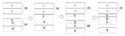
- FIG. 1 is a diagram showing a method of pre-lithiating an electrode according to an exemplary embodiment of the present application.
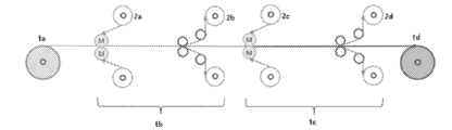
- Figure 2 is a diagram of an electrode pre-lithiation device according to an exemplary embodiment of the present application.
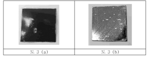
- Figure 3 is a diagram showing the electrode shape according to Example 1.
- Figure 3 (a) shows an electrode onto which the intermediate layer A according to Example 1 is transferred
- Figure 3 (b) shows an electrode onto which a lithium layer is transferred onto the electrode according to Figure 3 (a). It's a degree.
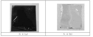
- Figure 4 is a diagram showing the electrode shape according to Example 2.
- Figure 4 (a) shows an electrode onto which the intermediate layer B according to Example 2 is transferred onto the electrode
- Figure 4 (b) shows an electrode onto which a lithium layer is transferred onto the electrode according to Figure 4 (a). It's a degree.
- Figure 5 is a diagram showing the cycle capacity of a half cell manufactured according to the pre-lithiation method according to the present invention.
- Figure 6 is a diagram showing the cycle capacity maintenance rate of a half cell manufactured according to the pre-lithiation method according to the present invention.
- 'p to q' means a range of 'p to q or less.
- specific surface area is measured by the BET method, and is specifically calculated from the amount of nitrogen gas adsorption under liquid nitrogen temperature (77K) using BELSORP-mino II from BEL Japan. That is, in the present application, the BET specific surface area may mean the specific surface area measured by the above measurement method.
- Dn refers to the average particle diameter and refers to the particle size at the n% point of the cumulative distribution of the number of particles according to particle size.
- D50 is the particle size at 50% of the cumulative distribution of particle numbers according to particle size
- D90 is the particle size at 90% of the cumulative distribution of particle numbers according to particle size
- D10 is 10% of the cumulative distribution of particle numbers according to particle size. This is the entrance diameter at the point.
- the average particle diameter can be measured using a laser diffraction method.
- a commercially available laser diffraction particle size measuring device for example, Microtrac S3500
- the difference in diffraction patterns according to particle size is measured when the particles pass through the laser beam, thereby distributing the particle size. Calculate .
- a polymer contains a certain monomer as a monomer unit means that the monomer participates in a polymerization reaction and is included as a repeating unit in the polymer.
- this is interpreted the same as saying that the polymer contains a monomer as a monomer unit.
- 'polymer' is understood to be used in a broad sense including copolymers, unless specified as 'homopolymer'.
- the weight average molecular weight (Mw) and number average molecular weight (Mn) are determined by using monodisperse polystyrene polymers (standard samples) of various degrees of polymerization commercially available for molecular weight measurement as standard materials, and using gel permeation chromatography (Gel Permeation). This is the polystyrene equivalent molecular weight measured by chromatography (GPC).
- molecular weight means weight average molecular weight unless otherwise specified.
- One embodiment of the present specification includes preparing an electrode coated with an electrode active material layer on both sides of an electrode current collector layer; Transferring the middle layer by lamination so that the middle layer is in contact with an intermediate layer laminate in which a first base layer, a first release layer, and an intermediate layer are sequentially stacked on electrode active material layers provided on both sides of the electrode; removing the first base layer and the first release layer after transferring the intermediate layer; Transferring a lithium metal layer by laminating a lithium metal layer laminate in which a second base layer, a second release layer, and a lithium metal layer are sequentially stacked on the intermediate layer of the active material layer to which the intermediate layer is transferred so that the lithium metal layer is in contact with the intermediate layer; removing the second base layer after transferring the lithium metal layer laminate; and pre-lithiating the electrode active material layer.
- FIG. 1 is a diagram showing a method of pre-lithiating an electrode according to an exemplary embodiment of the present application.
- the electrode active material layer 20 is described as being formed on one side of the electrode current collector layer 10, but the electrode active material layer 20 formed on both sides of the electrode current collector layer 10 is simply expressed as one side. That is, the electrode active material layer 20 is applied to both sides of the electrode current collector layer 10, and other prelithiation methods may be the same.
- a method for pre-lithiating an electrode according to an exemplary embodiment of the present invention is to manufacture a pre-lithiated electrode through two transfer processes. Specifically, when manufacturing a pre-lithiated electrode, a process of transferring the middle layer to the upper electrode active material layer is included in order to minimize the uneven pre-lithiation and suppress lithium loss due to side reactions during the electrode pre-lithiation process. , the lithium metal does not directly contact the electrode active material layer, so it has the feature of being able to control the pre-lithiation rate.
- the intermediate layer is formed in a dry-on-dry format.
- the electrode prelithiation method includes preparing an electrode coated with an electrode active material layer on at least one surface of the electrode current collector layer.
- an electrode can be prepared by coating an electrode slurry containing an electrode composition to be described later on at least one side of the electrode current collector layer.
- the electrode slurry includes an electrode active material layer composition; and a slurry solvent.
- the solid content of the electrode slurry may satisfy 5% or more and 80% or less.
- the solid content of the electrode slurry may satisfy the range of 5% to 80%, preferably 10% to 75%, and more preferably 20% to 70%.
- the solid content of the electrode slurry may mean the content of the electrode active material layer composition contained in the electrode slurry, and may mean the content of the electrode active material composition based on 100 parts by weight of the electrode slurry.
- the viscosity is appropriate when forming the electrode active material layer, thereby minimizing particle agglomeration of the electrode active material layer composition, thereby enabling efficient formation of the electrode active material layer.
- the slurry solvent is not limited thereto as long as it can dissolve the electrode active material layer composition, but specifically, NMP or distilled water can be used.
- the electrode according to an exemplary embodiment of the present application can be formed by coating and drying the electrode slurry on an electrode current collector layer.
- the slurry solvent in the electrode slurry may be dried.
- the slurry solvent may be dried through the drying step, thereby coating at least one surface of the electrode current collector layer with an electrode active material layer.
- the electrode current collector layer generally has a thickness of 1 ⁇ m to 100 ⁇ m.
- This electrode current collector layer is not particularly limited as long as it has high conductivity without causing chemical changes in the battery, for example, copper, stainless steel, aluminum, nickel, titanium, calcined carbon, copper or stainless steel. Surface treatment of carbon, nickel, titanium, silver, etc., aluminum-cadmium alloy, etc. can be used.
- the bonding power of the electrode active material can be strengthened by forming fine irregularities on the surface, and it can be used in various forms such as films, sheets, foils, nets, porous materials, foams, and non-woven fabrics.
- the thickness of the electrode current collector layer may be 1 ⁇ m or more and 100 ⁇ m or less, and the thickness of the electrode active material layer may be 20 ⁇ m or more and 500 ⁇ m or less.
- the thickness may vary depending on the type and purpose of the electrode used and is not limited to this.
- the electrode active material layer includes a negative electrode active material; electrode conductive material; and an electrode binder.
- the electrode active material layer is a negative electrode active material; electrode conductive material; And the electrode binder includes a silicon-based active material; electrode conductive material; This may mean that it includes an electrode active material layer composition including an electrode binder.
- the silicon-based active material may contain metal impurities, impurities that may occur during the purification process of the silicon-based active material, and the content may include 1 part by weight or less based on 100 parts by weight of the silicon-based active material. .
- pure silicon (Si) may be used as the silicon-based active material.
- the average particle diameter (D50) of the active material of the present invention may be 100 nm to 20 ⁇ m, specifically 500 nm to 15 ⁇ m, and more specifically 1 ⁇ m to 10 ⁇ m.
- the average particle diameter is within the above range, the specific surface area of the particles is within an appropriate range, and the viscosity of the electrode slurry is within an appropriate range. Accordingly, dispersion of the particles constituting the electrode slurry becomes smooth.
- the size of the active material is greater than the above lower limit, the contact area between the active material particles and the conductive material is excellent due to the composite of the conductive material and the binder in the electrode slurry, and the possibility of the conductive network being maintained increases, thereby increasing the capacity retention rate. This increases.
- the average particle diameter satisfies the above range, excessively large active material particles are excluded to form a smooth surface of the electrode, thereby preventing current density unevenness during charging and discharging.
- the active material generally has a characteristic BET surface area.
- the BET surface area of the active material is preferably 0.01 to 150.0 m 2 /g, more preferably 0.1 to 100.0 m 2 /g, particularly preferably 0.2 to 80.0 m 2 /g, most preferably 0.2 to 18.0 m 2 It is /g. BET surface area is measured according to DIN 66131 (using nitrogen).
- the active material may be 60 parts by weight or more based on 100 parts by weight of the electrode active material layer composition.
- the active material may contain at least 60 parts by weight, preferably at least 65 parts by weight, more preferably at least 70 parts by weight, based on 100 parts by weight of the electrode active material layer composition, and 95 parts by weight. Or less, preferably 90 parts by weight or less, more preferably 80 parts by weight or less.
- the electrode active material layer composition according to the present application uses a conductive material and a binder that can control the volume expansion rate during the charging and discharging process even when a silicon-based active material with a significantly high capacity is used within the above range, so that even within the above range, the electrode active material layer composition is used. It does not degrade performance and has excellent output characteristics during charging and discharging.
- the active material may have a non-spherical shape and the degree of sphericity is, for example, 0.9 or less, for example, 0.7 to 0.9, for example, 0.8 to 0.9, for example, 0.85 to 0.9. .
- the circularity is determined by the following equation 1, where A is the area and P is the boundary line.
- the electrode conductive material is a point-shaped conductive material; linear conductive material; And it may include one or more selected from the group consisting of planar conductive materials.
- the point-shaped conductive material can be used to improve conductivity in the electrode, and preferably has conductivity without causing chemical changes.
- the conductive materials include natural graphite, artificial graphite, carbon black, acetylene black, Ketjen black, channel black, Paneth black, lamp black, thermal black, conductive fiber, fluorocarbon, aluminum powder, nickel powder, zinc oxide, and titanic acid. It may be at least one selected from the group consisting of potassium, titanium oxide, and polyphenylene derivatives, and preferably may include carbon black in terms of realizing high conductivity and excellent dispersibility.
- the point-shaped conductive material may have a BET specific surface area of 40 m 2 /g or more and 70 m 2 /g or less, preferably 45 m 2 /g or more and 65 m 2 /g or less, more preferably 50 m 2 /g. It may be more than /g and less than 60m 2 /g.
- the particle diameter of the point-shaped conductive material may be 10 nm to 100 nm, preferably 20 nm to 90 nm, and more preferably 20 nm to 60 nm.
- the conductive material may include a planar conductive material.
- planar conductive material improves conductivity by increasing surface contact between silicon particles within the electrode, and at the same time can play a role in suppressing disconnection of the conductive path due to volume expansion, and may be expressed as a plate-type conductive material or a bulk-type conductive material. You can.
- the planar conductive material may include at least one selected from the group consisting of plate-shaped graphite, graphene, graphene oxide, and graphite flakes, and may preferably be plate-shaped graphite.
- the average particle diameter (D50) of the planar conductive material may be 2 ⁇ m to 7 ⁇ m, specifically 3 ⁇ m to 6 ⁇ m, and more specifically 4 ⁇ m to 5 ⁇ m. .
- D50 average particle diameter
- the planar conductive material has a D10 of 0.5 ⁇ m or more and 1.5 ⁇ m or less, a D50 of 2.5 ⁇ m or more and 3.5 ⁇ m or less, and a D90 of 7.0 ⁇ m or more and 15.0 ⁇ m or less.
- An electrode composition is provided.
- the planar conductive material is a high specific surface area planar conductive material having a high BET specific surface area; Alternatively, a low specific surface area planar conductive material can be used.
- the planar conductive material includes a high specific surface area planar conductive material;
- a planar conductive material with a low specific surface area can be used without limitation, but in particular, the planar conductive material according to the present application can be affected to some extent by dispersion on electrode performance, so it is possible to use a planar conductive material with a low specific surface area that does not cause problems with dispersion. This may be particularly desirable.
- the planar conductive material may have a BET specific surface area of 1 m 2 /g or more.
- the planar conductive material may have a BET specific surface area of 1 m 2 /g or more and 500 m 2 /g or less, preferably 5 m 2 /g or more and 300 m 2 /g or less, more preferably 5 m 2 / g. It may be more than g and less than 250m 2 /g.
- the planar conductive material is a high specific surface area planar conductive material, and has a BET specific surface area of 50 m 2 /g or more and 500 m 2 /g or less, preferably 80 m 2 /g or more and 300 m 2 /g or less, more preferably In other words, it can satisfy the range of 100m 2 /g or more and 300m 2 /g or less.
- the planar conductive material is a low specific surface area planar conductive material, and the BET specific surface area is 1 m 2 /g or more and 40 m 2 /g or less, preferably 5 m 2 / g or more and 30 m 2 /g or less, more preferably In other words, it can satisfy the range of 5m 2 /g or more and 25m 2 /g or less.
- Other conductive materials may include linear conductive materials such as carbon nanotubes.
- the carbon nanotubes may be bundled carbon nanotubes.
- the bundled carbon nanotubes may include a plurality of carbon nanotube units.
- the 'bundle type' herein refers to a bundle in which a plurality of carbon nanotube units are arranged side by side or entangled in substantially the same orientation along the longitudinal axis of the carbon nanotube units, unless otherwise specified. It refers to a secondary shape in the form of a bundle or rope.
- the carbon nanotube unit has a graphite sheet in the shape of a cylinder with a nano-sized diameter and an sp2 bond structure.
- the characteristics of a conductor or semiconductor can be displayed depending on the angle and structure at which the graphite surface is rolled.
- the bundled carbon nanotubes can be uniformly dispersed during electrode manufacturing and can smoothly form a conductive network within the electrode, improving the conductivity of the electrode.
- the electrode conductive material may be in an amount of 10 parts by weight or more and 40 parts by weight or less based on 100 parts by weight of the electrode active material layer composition.
- the electrode conductive material is 10 parts by weight or more and 40 parts by weight or less, preferably 10 parts by weight or more and 30 parts by weight or less, more preferably 10 parts by weight or more, based on 100 parts by weight of the electrode active material layer composition. It may contain 20 parts by weight or less.
- the electrode binder is polyvinylidene fluoride-hexafluoropropylene copolymer (PVDF-co-HFP), polyvinylidenefluoride, polyacrylonitrile, Polymethylmethacrylate, polyvinyl alcohol, carboxymethylcellulose (CMC), starch, hydroxypropylcellulose, regenerated cellulose, polyvinylpyrrolidone, tetrafluoroethylene, polyethylene, polypropylene, polyacrylic acid, ethylene.
- PVDF-co-HFP polyvinylidene fluoride-hexafluoropropylene copolymer
- EPDM propylene-diene monomer
- SBR styrene butadiene rubber
- fluororubber poly acrylic acid
- materials whose hydrogen is replaced with Li, Na, or Ca etc. It may include at least one of the following, and may also include various copolymers thereof.
- the electrode binder serves to hold the active material and the conductive material to prevent distortion and structural deformation of the electrode structure in the volume expansion and relaxation of the silicon-based active material. If the above role is satisfied, the electrode binder serves as a general Any binder can be applied, specifically, a water-based binder can be used, and more specifically, a PAM-based binder can be used. A thickener may be included along with the binder, and the thickener may specifically be CMC.
- the electrode prelithiation method is an intermediate layer of an intermediate layer laminate in which a first base layer, a first release layer, and an intermediate layer are sequentially stacked on an electrode active material layer provided on at least one surface of the electrode. Transferring the middle layer by lamination so that it is in contact with each other; and removing the first base layer and the first release layer after transferring the intermediate layer.
- the intermediate layer laminate 200 in which the first base layer 40, the first release layer 30, and the intermediate layer 35 are sequentially stacked on the electrode active material layer 20 can be confirmed. You can. At this time, it can be confirmed that the lamination process is performed so that the intermediate layer 35 and the electrode active material layer 20 are in contact with each other. After the intermediate layer lamination, the first base layer 40 and the first release layer 30 are removed, and through this, it can be confirmed that the intermediate layer 35 is formed on the upper part of the electrode active material layer 20.
- the intermediate layer laminate may include a structure in which a first base layer, a first release layer, and an intermediate layer are sequentially stacked.
- the first base layer is polyethylene terephthalate (PET), polyimide (PI), poly(methylmethacrylate), PMMA), poly It may be one or more types selected from the group consisting of polypropylene, polyethylene, and polycarbonate.
- the thickness of the first base layer may be 1 ⁇ m or more and 300 ⁇ m or less, and may satisfy the range of 5 ⁇ m or more and 200 ⁇ m or less, and 10 ⁇ m or more and 100 ⁇ m or less.
- a first release layer is further included on the surface where the first base layer and the middle layer of the middle layer laminate are in contact. can do.
- the first base layer may have a first release layer formed on at least one side, and may have a first release layer formed on both sides. Due to the first release layer, it is possible to prevent reverse peeling problem in which the intermediate layer is transferred onto the first base layer during the winding process for transferring the deposited intermediate layer onto the electrode active material layer, and also, the intermediate layer can be transferred onto the electrode active material layer. After transferring, the first base layer can be easily separated.
- the first release layer may include at least one selected from the group consisting of silicone-modified polyester, Si, melamine, and fluorine, in which a silicone chain is grafted to a polyester main chain.
- the first release layer may be formed by a coating method, for example, the coating method includes dip coating, spray coating, or spin coating. , it may be a method selected from the group consisting of die coating, gravure coating, micro-gravure coating, comma coating, and roll coating. It is not limited to this, and various coating methods that can be used in the art to form a coating layer can be used.
- the intermediate layer includes an intermediate layer composition
- the intermediate layer composition includes a polymer; mineral; active material; and a conductive material. It provides a method for pre-lithiating an electrode comprising at least one selected from the group consisting of.
- the polymer may be an amorphous thermoplastic polymer, such as poly(methyl methacrylate), PMMA, polystyrene (PS), polyvinyl chloride, PVC), polycarbonate (PC), and ABS resin (Acrylonitrile Butadiene Styrene) can be used, and polymethyl methacrylate (Poly(methyl methacrylate), PMMA), an acrylic polymer, is preferred.
- amorphous thermoplastic polymer such as poly(methyl methacrylate), PMMA, polystyrene (PS), polyvinyl chloride, PVC), polycarbonate (PC), and ABS resin (Acrylonitrile Butadiene Styrene) can be used, and polymethyl methacrylate (Poly(methyl methacrylate), PMMA), an acrylic polymer, is preferred.
- the middle layer when the polymer according to an exemplary embodiment of the present application is used as an intermediate layer composition, lithium transfer performance can be improved by providing adhesion.
- the middle layer when the middle layer does not contain a conductive material and is made only of polymers, the middle layer acts as a barrier layer between lithium and the electrode, suppressing electrode pre-lithiation, and the middle layer dissolves in the electrolyte after electrolyte injection during battery manufacturing. It has the characteristic that pre-lithiation occurs when the electrode comes into contact with lithium. Therefore, when the middle layer is composed only of polymers, the polymer has the property of dissolving in the electrolyte and the occurrence of side reactions during battery operation is minimized.
- the polymer according to an exemplary embodiment of the present application may be included in an amount of 80 parts by weight or more and 100 parts by weight or less based on 100 parts by weight of the total middle layer composition.
- the polymer When the polymer is composed of 100 parts by weight based on 100 parts by weight of the total intermediate layer composition, it has the characteristics of a barrier layer against pre-lithiation reaction in a dry state, and when it contains a conductive material, etc., electro-lithiation of the electrode through the intermediate layer occurs in a dry state. This is possible, and the pre-lithiation rate increases as the content of the conductive material increases.
- the inorganic material may be silica (SiO 2 ), alumina (Al 2 O 3 ), tungsten oxide (WO 3 ), vanadium oxide (V 2 O 5 ), etc. You can.
- the active material may be LiMO 2 (M: including at least one of Ni, Mn, and Co), which is a lithium metal oxide. Additionally, the active materials include graphite, soft carbon, and hard carbon.
- the description of the active material and the conductive material may be applied to the description of the electrode active material and the electrode conductive material described above.
- the conductive material may be a point-shaped conductive material or a linear conductive material, and the point-shaped conductive material and the linear conductive material may be used together.
- the conductive material may preferably include one or more selected from the group consisting of carbon black, single-walled carbon nanotubes (SWCNTs), and multi-walled carbon nanotubes (MWCNTs). It is not limited to this.
- the conductive material preferably includes any one selected from the group consisting of carbon black, single-walled carbon nanotubes (SWCNTs), and multi-walled carbon nanotubes (MWCNTs) as the first conductive material. It can be done and another one can be included as the second conductive material, but it is not limited to this.
- the middle layer composition may include a polymer or a first conductive material and a second conductive material at a weight ratio of 100:0 to 60:40, preferably 100:0 to 80:20. It can be included in a weight ratio of .
- An intermediate layer having the above composition is formed on the upper part of the electrode active material layer, and the intermediate layer can serve as a buffer layer that prevents rapid pre-lithiation by preventing lithium metal from directly contacting the upper part of the electrode active material layer.
- the intermediate layer according to the present application prevents direct contact between lithium metal and the electrode active material layer, controls the speed of pre-lithiation, allows pre-lithiation within the electrode active material layer to proceed uniformly, and prevents side reactions accompanying rapid pre-lithiation. It can play a role in reducing lithium loss by suppressing it.
- a method for pre-lithiating an electrode wherein the thickness of the intermediate layer is 200 ⁇ m or less.
- the thickness of the intermediate layer may be 100 ⁇ m or less, 75 ⁇ m or less, preferably 50 ⁇ m or less, and 100 nm or more, preferably 300 nm or more.
- the thickness of the intermediate layer may be 10 ⁇ m or less, 5 ⁇ m or less, preferably 1 ⁇ m or less, and 100 nm or more, preferably 300 nm or more.
- the intermediate layer can be easily formed on the first base layer and the first release layer, and the intermediate layer can be easily transferred to the electrode.
- the middle layer satisfies the above thickness and acts as an appropriate resistance for lithium ions during pre-lithiation, allowing the pre-lithiation rate to be appropriately adjusted. Even if it remains on the top of the electrode active material layer after cell assembly, its role as electrode resistance can be minimized. You will have
- the middle layer according to the present application is characterized in that the middle layer composition is coated on the top of the first release layer, dried, and then transferred back to the top of the electrode active material layer.
- the step of transferring the intermediate layer provides a method of pre-lithiating an electrode including a dry on dry process.
- the intermediate layer is not a wet on dry process in which the intermediate layer composition is coated on the upper part of the electrode active material layer, but rather a dry on dry process in which the intermediate layer laminate with the intermediate layer is transferred to the upper part of the electrode active material layer. is formed by
- the wet on dry process may refer to a process of coating by applying a coating layer composition on top of the dried layer, and the dry on dry process may refer to a process of coating the dried layer on top of the dried layer. This may refer to a process of transferring the layer itself.
- the intermediate layer according to an exemplary embodiment of the present application solves the problem of an increase in electrode resistance due to the intermediate layer composition penetrating into the pores of the electrode active material layer and filling or blocking the electrode pores, which is a problem when proceeding in a wet-on-dry format. is the main feature of the present invention.
- the middle layer composition itself is a fluid composition and is applied and coated on the upper part of the electrode active material layer in which pores are formed, a phenomenon occurs that penetrates into the pores of the electrode active material layer due to the fluidity and capillary phenomenon of the middle layer composition, resulting in The above problems arise.
- the intermediate layer according to the present application can solve the above problem by being formed on the upper part of the electrode active material layer by transfer method.
- the intermediate layer is formed through a dry on dry process as described above, it can be simultaneously transferred to the upper part of the electrode active material layer provided on both sides of the electrode current collector layer.
- the intermediate layer formation according to the present application is dry on dry.
- the process forms an intermediate layer on both sides at the same time, which solves the above-mentioned problems and improves the economic efficiency of the process itself.
- a method of pre-lithiating an electrode wherein the first adhesive force of the surface where the intermediate layer and the first release layer are in contact is 10 gf/inch or more and 150 gf/inch or less.
- the first adhesive strength may satisfy a range of 10 gf/inch or more and 150 gf/inch or less, specifically 15 gf/inch or more and 100 gf/inch or less, and more specifically, 20 gf/inch or more and 100 gf/inch or less. .
- the first adhesive force can be measured using peel tester equipment (AR-2000), a first release layer (Nitto31B), and a rubber roller (2 kg). Specifically, after attaching the first release layer to one side of the middle layer, it is attached back and forth once using a rubber roller to form a structure in which the first release layer and the middle layer are stacked, and stored at room temperature for 24 hours. Afterwards, the first release layer was peeled to a width of 25 mm and the force was measured. The peel speed was 300 mm/min and the peel angle was 180°.
- the intermediate layer when the first adhesive strength satisfies the above range, the intermediate layer can be easily transferred to the upper part of the electrode active material layer, and the manufacturing of the intermediate layer laminate is easy, and reverse transfer to the first base layer can also be prevented. It has characteristics.
- a method for pre-lithiating an electrode in which the surface roughness (S a ) of the intermediate layer is lower than 1/5 of the surface roughness (S a ) of the electrode active material layer.
- the surface roughness (S a ) of the intermediate layer refers to the surface roughness of the surface in contact with the lithium metal layer, and is measured using a CLSM (Confocal Laser Scanning Microscope) instrument, specifically Olympus OLS 5100, with a magnification of 50 times, The scanning area is 260 ⁇ m x 260 ⁇ m, and the average value is used after measuring 10 times per sample.
- CLSM Confocal Laser Scanning Microscope
- the electrode active material layer containing the active material has a surface roughness (S a ) in the range of about 0.4 ⁇ m to 0.7 ⁇ m, which is very high compared to the surface roughness of the lithium metal layer, which is 0.04 ⁇ m to 0.06 ⁇ m.
- the contact point between the lithium metal and the electrode active material layer is non-uniform, which increases the formation of by-products during prelithiation.
- the surface roughness is adjusted. It may include an intermediate layer having.
- the surface roughness of the intermediate layer according to the present application is designed to be less than 1/5 of the surface roughness (S a ) of the electrode active material layer, so that lithium metal can be more uniformly transferred to the upper part of the electrode active material layer.
- the method may include removing the first base layer and the first release layer after transferring the intermediate layer. That is, the first base layer and the first release layer serve as a transfer laminate to facilitate transfer onto the electrode active material layer of the intermediate layer, and also correspond to a laminate for performing a dry-on-dry process.
- lamination is performed so that the lithium metal layer of the lithium metal layer laminate is sequentially laminated on the intermediate layer of the active material layer to which the intermediate layer is transferred, a second base layer, a second release layer, and a lithium metal layer. transferring the lithium metal layer; and removing the second base layer after transferring the lithium metal layer laminate.
- the lithium metal layer of the lithium metal layer laminate in which the second base layer, the second release layer, and the lithium metal layer are sequentially stacked on the intermediate layer of the electrode active material layer to which the intermediate layer is transferred is in contact with the lithium metal layer. Transferring the lithium metal layer by lamination;
- At least one of the steps between transferring the lithium metal layer and removing the second base layer may further include pre-lithiating the electrode active material layer. That is, the step of pre-lithiating the electrode active material layer may be performed at any stage after transferring the lithium metal layer onto the intermediate layer of the electrode active material layer to which the intermediate layer has been transferred.
- a second base layer 41, a second release layer 31, and a lithium metal layer 36 are formed on the upper part of the electrode on which the intermediate layer 35 is formed on the electrode active material layer 20. It can be seen that the sequentially stacked lithium metal layer stack 300 is laminated. Afterwards, the second base layer 41 is removed, and the electrode current collector layer 10, electrode active material layer 20, middle layer 35, lithium metal layer 36, and second release layer 31 are sequentially stacked. It can be confirmed that a structure is formed.
- the lithium metal layer laminate may include a structure in which a second base layer, a second release layer, and a lithium metal layer are sequentially stacked.
- the second base layer is made of polyethylene terephthalate (PET), polyimide (PI), poly(methylmethacrylate), PMMA), poly It may be one or more types selected from the group consisting of polypropylene, polyethylene, and polycarbonate.
- the description of the above-described first base layer may be applied to the second base layer in the same manner.
- the description of the above-described first release layer may be applied to the second release layer in the same manner.
- the deposition method for depositing the lithium metal layer on the second base layer on which the second release layer is formed includes vacuum deposition, chemical vapor deposition, and chemical vapor deposition ( It may be selected from CVD (chemical vapor deposition), and physical vapor deposition (physical vapor deposition), but is not limited thereto, and a variety of deposition methods used in the industry may be used.
- the transfer process may be performed through roll pressing by applying a load of 10 kgf to 500 kgf to the electrode on which the lithium metal layer laminate is laminated.
- a process of removing the second base layer is included, and when removed, direct contact between the lithium metal layer and the air can be prevented by including the second release layer according to the present application, thereby providing the feature of protecting the lithium metal layer. do.
- the thickness of the lithium metal layer may be 1 ⁇ m or more and 10 ⁇ m or less, and preferably may be 3 ⁇ m or more and 10 ⁇ m or less.
- the thickness of the lithium metal layer satisfies the above range, transfer of the lithium metal layer to the electrode active material layer can occur efficiently, and reverse transfer can be prevented.
- the intermediate layer is prevented from coming into direct contact with the electrode active material layer, thereby delaying the progress of the pre-lithiation process.
- the intermediate layer according to the present application is first transferred to the top of the lithium metal layer and then laminated to the electrode active material layer, unlike the present application, the intermediate layer and the lithium metal layer are laminated to the electrode active material layer at the same time, so that pre-lithiation proceeds simultaneously. It may be difficult to derive uniform contact conditions at the top of the electrode.
- the electrode pre-lithiating method includes pre-lithiating the electrode active material layer.
- the above step may mean that pre-lithiation can proceed from the transfer of the lithium metal layer onto the electrode active material layer on which the intermediate layer is formed, and can refer to the stage from the point when pre-lithiation occurs to the stage where all lithium metal layers disappear to the naked eye and pre-lithiation is completed.
- the step of pre-lithiating the electrode may be performed under pressure conditions of 5 kgf/cm 2 to 20 kgf/cm 2 at a temperature of 60°C to 80°C.
- the pre-lithiation completion time can satisfy the range of 1 hour to 24 hours.
- an intermediate layer is formed on the top of the electrode active material layer according to the present application, preventing rapid pre-lithiation, and satisfying the pre-lithiation completion time as described above, allowing pre-lithiation to proceed more uniformly.
- composition of the middle layer is made of a polymer
- pre-lithiation is suppressed in a dry state and pre-lithiation may occur after electrolyte injection during battery assembly.
- an electrode for a lithium secondary battery pre-lithiated according to the electrode pre-lithiation method according to the present application is provided.
- a pre-lithiated electrode according to the present application; A separator positioned between the electrode and the counter electrode; It provides a lithium secondary battery including; and an electrolyte.
- the electrode active material layer includes a positive electrode active material; electrode conductive material; and an electrode binder.
- the electrode active material layer is a positive electrode active material; electrode conductive material; And including an electrode binder means a positive electrode active material; electrode conductive material; and a positive electrode active material layer composition including an electrode binder.
- the positive electrode when the electrode is a positive electrode, the positive electrode is formed on a positive electrode current collector and may include a positive electrode active material layer containing the positive electrode active material.
- the positive electrode current collector is not particularly limited as long as it is conductive without causing chemical changes in the battery, for example, stainless steel, aluminum, nickel, titanium, fired carbon, or carbon on the surface of aluminum or stainless steel. , surface treated with nickel, titanium, silver, etc. can be used. Additionally, the positive electrode current collector may typically have a thickness of 3 to 500 ⁇ m, and fine irregularities may be formed on the surface of the current collector to increase the adhesion of the positive electrode active material. For example, it can be used in various forms such as films, sheets, foils, nets, porous materials, foams, and non-woven materials.
- the positive electrode active material layer composition may be a commonly used positive electrode active material.
- the positive electrode active material is a layered compound such as lithium cobalt oxide (LiCoO 2 ), lithium nickel oxide (LiNiO 2 ), or a compound substituted with one or more transition metals; Lithium iron oxide such as LiFe 3 O 4 ; Lithium manganese oxide with the formula Li 1+c1 Mn 2-c1 O 4 (0 ⁇ c1 ⁇ 0.33), LiMnO 3 , LiMn 2 O 3 , LiMnO 2 , etc.; lithium copper oxide (Li 2 CuO 2 ); Vanadium oxides such as LiV 3 O 8 , V 2 O 5 , and Cu 2 V 2 O 7 ; Chemical formula LiNi 1-c2 M c2 O 2 (where M is at least one selected from the group consisting of Co, Mn, Al, Cu, Fe, Mg, B and Ga, and satisfies 0.01 ⁇ c2 ⁇ 0.3).
- LiMn 2-c3 M c3 O 2 (where M is at least one selected from the group consisting of Co, Ni, Fe, Cr, Zn and Ta, and satisfies 0.01 ⁇ c3 ⁇ 0.1), formula LiM 1-c4 M' c4 PO 4 (here, M: Transition metal, M' is at least one selected from the group consisting of Co, Ni, Fe, Cr, Zn and Ta, and satisfies 0.01 ⁇ c4 ⁇ 0.1) or Li 2 Mn 3 MO 8 (here, M is at least one selected from the group consisting of Fe, Co, Ni, Cu and Zn) Lithium manganese composite oxide represented by; Examples include LiMn 2 O 4 in which part of Li in the chemical formula is replaced with an alkaline earth metal ion, but it is not limited to these.
- the anode may be Li-metal.
- the electrode active material layer includes a positive electrode active material; electrode conductive material; and an electrode binder.
- the positive electrode active material layer may include the positive electrode active material described above, a positive conductive material, and a positive electrode binder.
- the anode conductive material is used to provide conductivity to the electrode, and can be used without particular limitation as long as it does not cause chemical change and has electronic conductivity in the battery being constructed.
- Specific examples include graphite such as natural graphite and artificial graphite; Carbon-based materials such as carbon black, acetylene black, Ketjen black, channel black, furnace black, lamp black, summer black, and carbon fiber; Metal powders or metal fibers such as copper, nickel, aluminum, and silver; Conductive whiskeys such as zinc oxide and potassium titanate; Conductive metal oxides such as titanium oxide; Or conductive polymers such as polyphenylene derivatives, etc., of which one type alone or a mixture of two or more types may be used.
- the positive electrode binder serves to improve adhesion between positive electrode active material particles and adhesion between the positive electrode active material and the positive electrode current collector.
- Specific examples include polyvinylidene fluoride (PVDF), vinylidene fluoride-hexafluoropropylene copolymer (PVDF-co-HFP), polyvinyl alcohol, polyacrylonitrile, and carboxymethyl cellulose (CMC). ), starch, hydroxypropylcellulose, regenerated cellulose, polyvinylpyrrolidone, tetrafluoroethylene, polyethylene, polypropylene, ethylene-propylene-diene polymer (EPDM), sulfonated-EPDM, styrene butadiene rubber. (SBR), fluorine rubber, or various copolymers thereof, and one type of these may be used alone or a mixture of two or more types may be used.
- PVDF polyvinylidene fluoride
- PVDF-co-HFP vinylidene flu
- the separator separates the electrode and the positive electrode and provides a passage for lithium ions to move, and can be used without particular restrictions as long as it is normally used as a separator in a secondary battery, especially for ion movement in the electrolyte. It is desirable to have low resistance and excellent electrolyte moisturizing ability.
- porous polymer films for example, porous polymer films made of polyolefin polymers such as ethylene homopolymer, propylene homopolymer, ethylene/butene copolymer, ethylene/hexene copolymer, and ethylene/methacrylate copolymer, or these.
- a laminated structure of two or more layers may be used.
- porous non-woven fabrics for example, non-woven fabrics made of high melting point glass fibers, polyethylene terephthalate fibers, etc.
- a coated separator containing ceramic components or polymer materials may be used to ensure heat resistance or mechanical strength, and may optionally be used in a single-layer or multi-layer structure.
- the electrolyte solution includes an organic liquid electrolyte solution, an inorganic liquid electrolyte, a solid polymer electrolyte, a gel-type polymer electrolyte solution, a solid inorganic electrolyte solution, and a molten inorganic electrolyte solution that can be used when manufacturing a lithium secondary battery. It is not limited to these.
- the electrolyte solution may include a non-aqueous organic solvent and a metal salt.
- non-aqueous organic solvent examples include N-methyl-2-pyrrolidinone, propylene carbonate, ethylene carbonate, butylene carbonate, dimethyl carbonate, diethyl carbonate, gamma-butylo lactone, and 1,2-dimethyl.
- Triesters trimethoxy methane, dioxoran derivatives, sulfolane, methyl sulfolane, 1,3-dimethyl-2-imidazolidinone, propylene carbonate derivatives, tetrahydrofuran derivatives, ether, methyl pyropionate, propionic acid.
- Aprotic organic solvents such as ethyl may be used.
- ethylene carbonate and propylene carbonate which are cyclic carbonates
- cyclic carbonates are high-viscosity organic solvents and have a high dielectric constant, so they can be preferably used because they easily dissociate lithium salts.
- These cyclic carbonates include dimethyl carbonate and diethyl carbonate. If linear carbonates of the same low viscosity and low dielectric constant are mixed and used in an appropriate ratio, an electrolyte with high electrical conductivity can be made and can be used more preferably.
- the metal salt may be a lithium salt, and the lithium salt is a material that is easily soluble in the non-aqueous electrolyte solution.
- anions of the lithium salt include F - , Cl - , I - , NO 3 - , N(CN) ) 2 - , BF 4 - , ClO 4 - , PF 6 - , (CF 3 ) 2 PF 4 - , (CF 3 ) 3 PF 3 - , (CF 3 ) 4 PF 2 - , (CF 3 ) 5 PF - , (CF 3 ) 6 P - , CF 3 SO 3 - , CF 3 CF 2 SO 3 - , (CF 3 SO 2 ) 2 N - , (FSO 2 ) 2 N - , CF 3 CF 2 (CF 3 ) 2 CO - , (CF 3 SO 2 ) 2 CH - , (SF 5 ) 3 C - , (CF 3 SO 2 )
- the electrolyte solution includes, for example, haloalkylene carbonate-based compounds such as difluoroethylene carbonate, pyridine, and trifluoroethylene for the purpose of improving battery life characteristics, suppressing battery capacity reduction, and improving battery discharge capacity.
- haloalkylene carbonate-based compounds such as difluoroethylene carbonate, pyridine, and trifluoroethylene
- One or more additives such as zolidine, ethylene glycol dialkyl ether, ammonium salt, pyrrole, 2-methoxy ethanol, or aluminum trichloride may be further included.
- One embodiment of the present invention provides a battery module including the lithium secondary battery as a unit cell and a battery pack including the same. Since the battery module and battery pack include the secondary battery with high capacity, high rate characteristics, and cycle characteristics, they are medium-to-large devices selected from the group consisting of electric vehicles, hybrid electric vehicles, plug-in hybrid electric vehicles, and power storage systems. It can be used as a power source.
- an electrode extraction unit that extracts an electrode coated with an electrode active material layer on both sides of the electrode current collector layer; an intermediate layer transfer unit that laminates an intermediate layer laminate in which a first base layer, a first release layer, and an intermediate layer are sequentially stacked on electrode active material layers provided on both sides of the electrode; A lithium metal layer transfer unit that laminates a lithium metal layer laminate in which a second base layer, a second release layer, and a lithium metal layer are sequentially stacked on the intermediate layer of the electrode active material layer to which the intermediate layer is transferred; and an electrode recovery unit. It provides an electrode pre-lithiation device including a.
- the intermediate layer transfer unit includes an intermediate layer laminate recovery unit for recovering the first base layer and the first release layer, and the lithium metal layer transfer unit is a lithium metal layer lamination unit for recovering the second base layer.
- An electrode pre-lithiation device comprising a sieve recovery unit is provided.
- the electrode prelithiation device is characterized by including two R2R processes in order to apply the above two transfer processes. Specifically, it has an electrode extraction unit, an intermediate layer transfer unit, a lithium metal layer transfer unit, and an electrode recovery unit, and two R2R processes are performed each in the intermediate layer transfer unit and the lithium metal transfer unit.
- FIG. 2 is a diagram of an electrode pre-lithiation device according to an exemplary embodiment of the present application. Specifically, it has an electrode extraction unit 1a including an electrode roll having an electrode current collector layer coated on both sides with an electrode active material layer, from which an electrode is extracted. Afterwards, the electrode passes through the middle layer transfer part 1b, and the middle layer can be transferred to both sides of the electrode active material layer. Specifically, the middle layer transfer part 1b includes the middle layer laminate lamination part 2a and the middle layer laminate removal part. (2b) may be included. It can be confirmed that R2R lamination is performed once in the lamination part of the intermediate layer laminate. Afterwards, it passes through the lithium metal layer transfer unit 1c and transfers the lithium metal layer onto the upper part of the middle layer.
- an electrode extraction unit 1a including an electrode roll having an electrode current collector layer coated on both sides with an electrode active material layer, from which an electrode is extracted.
- the electrode passes through the middle layer transfer part 1b, and the middle layer can be transferred to both sides of the electrode active material layer
- the lithium metal layer transfer part 1c includes a lithium metal layer stack lamination part 2c and a lithium metal layer stack removal part 2d. At this time, it can be confirmed that R2R lamination is progressing in the lithium metal layer laminate lamination part. Afterwards, it consists of an electrode recovery unit (1d) that recovers the electrode.
- the electrode pre-lithiation device corresponds to a device characterized by transferring the intermediate layer through a dry on dry process and performing two R2R transfers to transfer the lithium metal layer.
- a positive electrode slurry was prepared by setting the solid content ratio of the positive electrode material (NCMA):conductive material (MWCNT):binder (PVDF-HFP) to 96wt%:2wt%:2wt% and using NMP as a solvent.
- the electrode slurry was coated on both sides of an aluminum current collector (thickness: 15 ⁇ m) so that the capacity per area based on single-sided coating was 4.2 mAh/cm 2 , dried in a vacuum oven at 130°C for 12 hours, and rolled to form an electrode active material.
- An electrode with a layer coated on both sides was manufactured.
- the intermediate layer laminate is a PET film base material coated with an adhesive acrylic polymer, and the intermediate layer laminate was manufactured by varying the thickness of the PET film and the middle layer.
- the lithium deposition film is a 25 ⁇ m thick PET substrate coated with a 500nm thick acrylic polymer release layer, and a 6.2 ⁇ m thick lithium layer is deposited on this release layer using thermal evaporation.
- the base film (PET) and release layer were removed to prepare an electrode to which the middle layer was transferred.
- the middle layer is peeled off at the interface between the release layer and the middle layer and transferred to the electrode.
- the base layer (PET) of the lithium deposition film is removed to form a multilayer (release layer/lithium layer) to which the lithium layer/release layer is transferred. /middle layer/electrode layer)
- An electrode was manufactured. (dry on dry method). (see Figure 3)
- Example 1 a multilayer electrode to which the middle layer and the lithium layer (including the release layer) were sequentially transferred was manufactured in the same manner as in Example 1, except that middle layer B was used instead of middle layer A. (see Figure 4)
- Example 1 the electrode to which the intermediate layer (A or B) and lithium metal layer were not transferred was named Pristine electrode (Comparative Example 1).
- Example 1 except that the intermediate layer (A or B) was not formed on the top of the electrode active material layer, and the lithium metal layer was directly transferred on top of the electrode active material layer provided on both sides of the electrode current collector layer. It was prepared in the same manner as.
- a coin half-cell was manufactured using the electrode manufactured by the method of Example 1 and Comparative Examples 1 and 2, and the initial charge/discharge capacity and cycle performance were evaluated, and the results are shown in Table 3 and Figure 5 below.
- the electrolyte used to manufacture the coin half cell was 1M LiPF 6 in EC/EMC (30:70 vol %), and a 150 ⁇ m thick lithium metal foil was used as the counter electrode.
- the C-rate was set to 0.1C
- charging was performed under the upper limit voltage of 4.3V, CCCV conditions, and cut-off current of 0.005C
- discharging was performed under the lower limit voltage of 3.0V and CC conditions.
- Cycle capacity measurement was conducted under the conditions of upper and lower limit voltage of 4.3V/3.0V, C-rate of 0.33C, charge CCCV, and discharge CC.
- the electrode according to Example 1 which manufactures an electrode including a lithium metal layer through a sequential transfer process, has a much higher initial charge capacity than the electrode manufactured according to Comparative Examples 1 and 2.
- the method according to Example 1 includes a process of transferring the intermediate layer to the upper part of the electrode active material layer to solve the problem of cracking of the surface active material for the high-capacity positive electrode active material, so that the lithium metal does not directly contact the electrode active material layer. It was confirmed that it has the characteristic of preventing rapid pre-lithiation of the active material.
- Example 1 as the intermediate layer was formed through the dry on dry process as described above, unlike the wet on dry process, the lithium metal layer was simultaneously transferred to the upper part of the electrode active material layer provided on both sides of the electrode current collector layer. There are features that can be done.
- Example 2 As the middle layer was formed to a thin thickness, the pre-lithiation rate could be appropriately adjusted, and even if a portion remained on the top of the electrode active material layer after cell assembly, its role as electrode resistance was minimized.
- the pristine electrode without the lithium metal layer of Comparative Example 1 was found to have inferior cycle performance compared to Example 1 (see FIG. 6).
- Comparative Example 2 In the case of Comparative Example 2, an intermediate layer is not formed, and the process of transferring the lithium metal layer directly to the upper part of the electrode is performed.
- Comparative Example 2 When proceeding as in Comparative Example 2, cracking of the active material particles on the electrode surface occurs due to rapid electrode pre-lithiation. A phenomenon occurred, and it was confirmed that cycle performance was reduced compared to Example 1 (see FIG. 6).
Landscapes
- Chemical & Material Sciences (AREA)
- Chemical Kinetics & Catalysis (AREA)
- Electrochemistry (AREA)
- General Chemical & Material Sciences (AREA)
- Engineering & Computer Science (AREA)
- Manufacturing & Machinery (AREA)
- Materials Engineering (AREA)
- Inorganic Chemistry (AREA)
- Crystallography & Structural Chemistry (AREA)
- Battery Electrode And Active Subsutance (AREA)
Abstract
Description
| 중간층 적층체 | 기재 필름 / 두께 | 중간층 조성 / 두께 |
| A | PET / 75㎛ | 점착성 아크릴계 고분자/ 50㎛ |
| B | PET / 35㎛ | 점착성 아크릴계 고분자/ 10㎛ |
| 리튬 증착 필름 | 기재 필름(두께) / 이형층(두께) | 리튬층 / 두께 |
| C | PET(25㎛)/아크릴계고분자(500nm) | 리튬 / 6.2㎛ |
| 전극 종류 | 초기 충전 용량(mAh/cm2) | 초기 방전 용량 (mAh/cm2) |
| 중간층/리튬층 전사 전극 (실시예 1) | 6.52 | 4.23 |
| Pristine 전극(비교예 1) | 4.94 | 4.23 |
| 리튬층 전사 전극 (비교예 2) | 5.36 | 3.55 |
Claims (14)
- 전극 집전체층의 적어도 일면에 전극 활물질층이 코팅된 전극을 준비하는 단계;상기 전극 활물질층 상에 제1 기재층, 제1 이형층 및 중간층이 순차적으로 적층된 중간층 적층체의 상기 중간층이 접하도록 라미네이션하여 중간층을 전사하는 단계;상기 중간층 전사 후 제1 기재층 및 제1 이형층을 제거하는 단계;상기 중간층이 전사된 전극 활물질층의 상기 중간층 상에 제2 기재층, 제2 이형층 및 리튬 금속층이 순차적으로 적층된 리튬 금속층 적층체의 상기 리튬 금속층이 접하도록 라미네이션하여 리튬 금속층을 전사하는 단계;상기 리튬 금속층 적층체 전사 후 제2 기재층을 제거하는 단계;를 포함하는 전극 전리튬화 방법.
- 청구항 1에 있어서,상기 중간층이 전사된 전극 활물질층의 상기 중간층 상에 제2 기재층, 제2 이형층 및 리튬 금속층이 순차적으로 적층된 리튬 금속층 적층체의 상기 리튬 금속층이 접하도록 라미네이션하여 리튬 금속층을 전사하는 단계;상기 리튬 금속층 적층체 전사 후 제2 기재층을 제거하는 단계; 또는상기 리튬 금속층을 전사하는 단계 및 제2 기재층을 제거하는 단계의 사이 단계 중 적어도 어느 하나의 단계에 상기 전극 활물질층을 전리튬화 하는 단계를 더 포함하는 것인 전극 전리튬화 방법.
- 청구항 1에 있어서,상기 중간층은 중간층 조성물을 포함하며,상기 중간층 조성물은 고분자; 무기물; 활물질; 및 도전재;로 이루어진 군에서 선택되는 1 이상을 포함하는 것인 전극 전리튬화 방법.
- 청구항 1에 있어서,상기 중간층의 두께는 50μm 이하인 것인 전극 전리튬화 방법.
- 청구항 1에 있어서,상기 중간층을 전사하는 단계는 드라이 온 드라이(dry on dry) 공정을 포함하는 것인 전극 전리튬화 방법.
- 청구항 1에 있어서,상기 중간층과 상기 제1 이형층이 접하는 면의 제1 접착력이 10gf/inch 이상 150gf/inch 이하인 것인 전극 전리튬화 방법.
- 청구항 1에 있어서,상기 전극 활물질층은 음극 활물질; 전극 도전재; 및 전극 바인더를 포함하며,상기 음극 활물질은 흑연, 소프트 카본, 하드 카본, SiOx (x=0), SiOx (0<x<2), Si/C, 금속 불순물, 및 Si 합금으로 이루어진 군에서 선택되는 1 이상을 포함하는 전극 전리튬화 방법.
- 청구항 1에 있어서,상기 전극 활물질층은 양극 활물질; 전극 도전재; 및 전극 바인더를 포함하며, 상기 양극 활물질은 LiNixCoyMnzO2 (x+y+z=1); LiNiaCobMncAldO2 (a+b+c+d=1); LiMn2O4; LiNi0.5Mn1.5O2; 및 LiMxFeyPO4 (M: Transition metal, x+y=1)로 이루어진 군에서 선택되는 1 이상을 포함하는 전극 전리튬화 방법.
- 청구항 1에 있어서,상기 중간층의 표면 거칠기(Sa)는 상기 전극 활물질층의 표면 거칠기(Sa) 보다 1/5 이하로 낮은 것인 전극 전리튬화 방법.
- 청구항 1에 있어서,상기 제1 기재층 및 상기 제2 기재층은 폴리에틸렌테레프탈레이트 (polyethylene terephthalate, PET), 폴리이미드 (polyimide, PI), 폴리메틸메타크릴산 (poly(methylmethacrylate), PMMA), 폴리프로필렌 (Polypropylene), 폴리에틸렌 (Polyethylene) 및 폴리카보네이트 (Polycarbonate)로 이루어진 군에서 선택된 1종 이상인 것인 전극 전리튬화 방법.
- 청구항 1에 있어서,상기 리튬 금속층의 두께는 1μm 이상 10μm 이하인 것인 전극 전리튬화 방법.
- 청구항 1 내지 11 중 어느 한 항의 전극 전리튬화 방법에 따라 전리튬화 된 리튬 이차 전지용 전극.
- 전극 집전체층의 양면에 전극 활물질층이 코팅된 전극이 추출되는 전극 추출부;상기 전극의 양면에 구비된 전극 활물질층 상에 제1 기재층, 제1 이형층 및 중간층이 순차적으로 적층된 중간층 적층체를 라미네이션하는 중간층 전사부;상기 중간층이 전사된 전극 활물질층의 상기 중간층 상에 제2 기재층, 제2 이형층 및 리튬 금속층이 순차적으로 적층된 리튬 금속층 적층체를 라미네이션하는 리튬 금속층 전사부; 및전극 회수부;를 포함하는 전극 전리튬화 장치.
- 청구항 13에 있어서,상기 중간층 전사부는 상기 제1 기재층 및 제2 이형층을 회수하는 중간층 적층체 회수부를 포함하고,상기 리튬 금속층 전사부는 상기 제2 기재층을 회수하는 리튬 금속층 적층체 회수부를 포함하는 것인 전극 전리튬화 장치.
Priority Applications (3)
| Application Number | Priority Date | Filing Date | Title |
|---|---|---|---|
| EP23799741.6A EP4418352A4 (en) | 2022-05-06 | 2023-05-08 | ELECTRODE PRE-LITHIATION METHOD, PRE-LITHIATED ELECTRODE FOR LITHIUM SECONDARY BATTERY, AND ELECTRODE PRE-LITHIATION DEVICE |
| JP2024529672A JP2024540562A (ja) | 2022-05-06 | 2023-05-08 | 電極前リチウム化方法、前リチウム化されたリチウム二次電池用電極、および電極前リチウム化装置 |
| CN202380014683.3A CN118302874A (zh) | 2022-05-06 | 2023-05-08 | 电极预锂化方法、锂二次电池的预锂化电极和电极预锂化设备 |
Applications Claiming Priority (2)
| Application Number | Priority Date | Filing Date | Title |
|---|---|---|---|
| KR20220055970 | 2022-05-06 | ||
| KR10-2022-0055970 | 2022-05-06 |
Publications (1)
| Publication Number | Publication Date |
|---|---|
| WO2023214860A1 true WO2023214860A1 (ko) | 2023-11-09 |
Family
ID=88646748
Family Applications (1)
| Application Number | Title | Priority Date | Filing Date |
|---|---|---|---|
| PCT/KR2023/006207 Ceased WO2023214860A1 (ko) | 2022-05-06 | 2023-05-08 | 전극 전리튬화 방법, 전리튬화된 리튬 이차 전지용 전극 및 전극 전리튬화 장치 |
Country Status (5)
| Country | Link |
|---|---|
| EP (1) | EP4418352A4 (ko) |
| JP (1) | JP2024540562A (ko) |
| KR (1) | KR20230156664A (ko) |
| CN (1) | CN118302874A (ko) |
| WO (1) | WO2023214860A1 (ko) |
Families Citing this family (1)
| Publication number | Priority date | Publication date | Assignee | Title |
|---|---|---|---|---|
| WO2026071654A1 (ko) * | 2024-09-25 | 2026-04-02 | 주식회사 엘지에너지솔루션 | 리튬 이차 전지용 전극의 제조 방법, 이로부터 제조된 리튬 이차 전지용 전극, 이를 포함하는 리튬 이차 전지 및 전리튬화용 전사 적층체 |
Citations (7)
| Publication number | Priority date | Publication date | Assignee | Title |
|---|---|---|---|---|
| JP2009080971A (ja) | 2007-09-25 | 2009-04-16 | Tokyo Univ Of Science | リチウムイオン電池用負極 |
| KR20190017417A (ko) * | 2017-08-11 | 2019-02-20 | 주식회사 엘지화학 | 리튬금속과 무기물 복합층을 이용한 전리튬화 |
| CN110828778A (zh) * | 2019-10-30 | 2020-02-21 | 复阳固态储能科技(溧阳)有限公司 | 一种三明治结构预锂化负极及锂离子电池 |
| KR20210029459A (ko) * | 2019-09-06 | 2021-03-16 | 주식회사 엘지화학 | 리튬 이차전지용 음극의 제조방법 |
| KR20210113264A (ko) * | 2019-01-15 | 2021-09-15 | 맥스웰 테크놀러지스 인코포레이티드 | 에너지 저장 장치를 전리튬화하기 위한 조성물 및 방법 |
| KR20220028422A (ko) * | 2020-08-28 | 2022-03-08 | 주식회사 엘지에너지솔루션 | 음극의 전리튬화 방법 |
| KR20220055970A (ko) | 2020-10-27 | 2022-05-04 | 연세대학교 산학협력단 | 사전 정보 학습 기반 영상 업스케일링 장치 및 방법 |
Family Cites Families (9)
| Publication number | Priority date | Publication date | Assignee | Title |
|---|---|---|---|---|
| JP5008180B2 (ja) * | 2006-02-13 | 2012-08-22 | 日立マクセルエナジー株式会社 | 非水二次電池 |
| JP5151188B2 (ja) * | 2006-03-09 | 2013-02-27 | パナソニック株式会社 | 転写用フィルム、およびそれを用いて形成された電気化学素子用の極板ならびにリチウム二次電池 |
| KR101984727B1 (ko) * | 2016-11-21 | 2019-05-31 | 주식회사 엘지화학 | 전극 및 이를 포함하는 리튬 이차 전지 |
| KR102140127B1 (ko) * | 2017-04-25 | 2020-07-31 | 주식회사 엘지화학 | 리튬 이차전지용 음극, 이의 제조방법 및 이것을 포함하는 리튬 이차전지 |
| JP6926654B2 (ja) * | 2017-05-11 | 2021-08-25 | 株式会社豊田自動織機 | リチウムドープ負極の製造方法 |
| US11450855B2 (en) * | 2018-01-26 | 2022-09-20 | Lg Energy Solution, Ltd. | Negative electrode for lithium secondary battery and lithium ion secondary battery including the same |
| KR102459678B1 (ko) * | 2018-10-31 | 2022-10-28 | 주식회사 엘지에너지솔루션 | 리튬 이차 전지용 음극, 이를 포함하는 리튬 이차 전지 및 이의 제조방법 |
| CN110010844B (zh) * | 2019-03-25 | 2022-04-12 | 合肥国轩高科动力能源有限公司 | 一种预锂负极的分级式压延成型方法 |
| CN114365312A (zh) * | 2020-07-21 | 2022-04-15 | 株式会社Lg新能源 | 引入了锂化延迟层的用于锂二次电池的负极及其制造方法 |
-
2023
- 2023-05-08 WO PCT/KR2023/006207 patent/WO2023214860A1/ko not_active Ceased
- 2023-05-08 CN CN202380014683.3A patent/CN118302874A/zh active Pending
- 2023-05-08 EP EP23799741.6A patent/EP4418352A4/en active Pending
- 2023-05-08 KR KR1020230059061A patent/KR20230156664A/ko active Pending
- 2023-05-08 JP JP2024529672A patent/JP2024540562A/ja active Pending
Patent Citations (7)
| Publication number | Priority date | Publication date | Assignee | Title |
|---|---|---|---|---|
| JP2009080971A (ja) | 2007-09-25 | 2009-04-16 | Tokyo Univ Of Science | リチウムイオン電池用負極 |
| KR20190017417A (ko) * | 2017-08-11 | 2019-02-20 | 주식회사 엘지화학 | 리튬금속과 무기물 복합층을 이용한 전리튬화 |
| KR20210113264A (ko) * | 2019-01-15 | 2021-09-15 | 맥스웰 테크놀러지스 인코포레이티드 | 에너지 저장 장치를 전리튬화하기 위한 조성물 및 방법 |
| KR20210029459A (ko) * | 2019-09-06 | 2021-03-16 | 주식회사 엘지화학 | 리튬 이차전지용 음극의 제조방법 |
| CN110828778A (zh) * | 2019-10-30 | 2020-02-21 | 复阳固态储能科技(溧阳)有限公司 | 一种三明治结构预锂化负极及锂离子电池 |
| KR20220028422A (ko) * | 2020-08-28 | 2022-03-08 | 주식회사 엘지에너지솔루션 | 음극의 전리튬화 방법 |
| KR20220055970A (ko) | 2020-10-27 | 2022-05-04 | 연세대학교 산학협력단 | 사전 정보 학습 기반 영상 업스케일링 장치 및 방법 |
Non-Patent Citations (1)
| Title |
|---|
| See also references of EP4418352A4 |
Also Published As
| Publication number | Publication date |
|---|---|
| KR20230156664A (ko) | 2023-11-14 |
| CN118302874A (zh) | 2024-07-05 |
| JP2024540562A (ja) | 2024-10-31 |
| EP4418352A4 (en) | 2025-08-27 |
| EP4418352A1 (en) | 2024-08-21 |
Similar Documents
| Publication | Publication Date | Title |
|---|---|---|
| WO2019117531A1 (ko) | 리튬 이차전지용 양극 활물질, 이의 제조방법, 이를 포함하는 리튬 이차전지용 양극 및 리튬 이차전지 | |
| WO2023146256A1 (ko) | 리튬 이차 전지용 전극의 전리튬화 방법, 전극 중간체 및 전극을 포함하는 리튬 이차 전지 | |
| WO2023121218A1 (ko) | 리튬 이차 전지용 음극의 전리튬화 방법, 리튬 이차 전지용 음극 및 음극을 포함하는 리튬 이차 전지 | |
| WO2023153716A1 (ko) | 전사 적층체, 리튬 이차 전지용 음극 제조 방법, 리튬 이차 전지용 음극 및 음극을 포함하는 리튬 이차 전지 | |
| WO2023120966A1 (ko) | 음극 조성물, 이를 포함하는 리튬 이차 전지용 음극 및 음극을 포함하는 리튬 이차 전지 | |
| WO2023059151A1 (ko) | 음극 조성물, 이를 포함하는 리튬 이차 전지용 음극, 음극을 포함하는 리튬 이차 전지 및 음극 조성물의 제조 방법 | |
| WO2023059016A1 (ko) | 리튬 이차 전지용 음극, 리튬 이차 전지용 음극의 제조 방법 및 음극을 포함하는 리튬 이차 전지 | |
| WO2023146254A1 (ko) | 전사 적층체, 리튬 이차 전지용 전극의 전리튬화 방법 및 전극을 포함하는 리튬 이차 전지 | |
| WO2023101426A1 (ko) | 리튬 이차 전지용 음극, 리튬 이차 전지용 음극 제조 방법 및 음극을 포함하는 리튬 이차 전지 | |
| WO2023096307A1 (ko) | 리튬 이차 전지용 음극, 리튬 이차 전지의 제조 방법 및 리튬 이차 전지 | |
| WO2023214711A1 (ko) | 리튬 이차 전지용 음극, 리튬 이차 전지용 음극의 제조 방법 및 음극을 포함하는 리튬 이차 전지 | |
| WO2023182852A1 (ko) | 음극 조성물, 리튬 이차 전지용 음극 및 음극을 포함하는 리튬 이차 전지 | |
| WO2023068601A1 (ko) | 리튬 이차 전지용 음극, 음극을 포함하는 리튬 이차 전지 및 리튬 이차 전지용 음극의 제조 방법 | |
| WO2023214860A1 (ko) | 전극 전리튬화 방법, 전리튬화된 리튬 이차 전지용 전극 및 전극 전리튬화 장치 | |
| WO2025150842A1 (ko) | 양극재, 이를 포함하는 양극 및 리튬 이차전지 | |
| WO2024054016A1 (ko) | 리튬 이차 전지용 음극, 리튬 이차 전지용 음극의 제조 방법 및 음극을 포함하는 리튬 이차 전지 | |
| WO2024144187A1 (ko) | 리튬 이차 전지용 음극, 리튬 이차 전지용 음극의 제조 방법 및 음극을 포함하는 리튬 이차 전지 | |
| WO2023249445A1 (ko) | 리튬 이차 전지용 음극, 리튬 이차 전지용 음극의 제조 방법 및 음극을 포함하는 리튬 이차 전지 | |
| WO2023149746A1 (ko) | 리튬 이차 전지용 음극의 제조 방법, 리튬 이차 전지용 음극 및 음극을 포함하는 리튬 이차 전지 | |
| WO2023059015A1 (ko) | 음극 조성물, 이를 포함하는 리튬 이차 전지용 음극, 음극을 포함하는 리튬 이차 전지 및 음극 조성물의 제조 방법 | |
| WO2023214844A1 (ko) | 전극 조립체의 제조 방법, 전극 조립체 및 이를 포함하는 리튬 이차 전지 | |
| WO2023224401A1 (ko) | 리튬 이차 전지용 전극의 제조 방법 및 전극을 포함하는 리튬 이차 전지 | |
| WO2024128784A1 (ko) | 리튬 이차 전지용 전극의 제조 방법, 전사 적층체 및 전극을 포함하는 리튬 이차 전지 | |
| WO2024136569A1 (ko) | 전사 적층체, 리튬 이차 전지용 음극의 제조 방법, 리튬 이차 전지용 음극 및 음극을 포함하는 리튬 이차 전지 | |
| WO2024128783A1 (ko) | 전사 적층체, 전사 적층체의 제조 방법, 리튬 이차 전지용 전극의 제조 방법 및 리튬 이차 전지 |
Legal Events
| Date | Code | Title | Description |
|---|---|---|---|
| 121 | Ep: the epo has been informed by wipo that ep was designated in this application |
Ref document number: 23799741 Country of ref document: EP Kind code of ref document: A1 |
|
| WWE | Wipo information: entry into national phase |
Ref document number: 18705837 Country of ref document: US |
|
| WWE | Wipo information: entry into national phase |
Ref document number: 202417037066 Country of ref document: IN |
|
| WWE | Wipo information: entry into national phase |
Ref document number: 2023799741 Country of ref document: EP |
|
| ENP | Entry into the national phase |
Ref document number: 2024529672 Country of ref document: JP Kind code of ref document: A |
|
| WWE | Wipo information: entry into national phase |
Ref document number: 202380014683.3 Country of ref document: CN |
|
| ENP | Entry into the national phase |
Ref document number: 2023799741 Country of ref document: EP Effective date: 20240516 |
|
| NENP | Non-entry into the national phase |
Ref country code: DE |