WO2023218891A1 - 生体用電極装置 - Google Patents
生体用電極装置 Download PDFInfo
- Publication number
- WO2023218891A1 WO2023218891A1 PCT/JP2023/015730 JP2023015730W WO2023218891A1 WO 2023218891 A1 WO2023218891 A1 WO 2023218891A1 JP 2023015730 W JP2023015730 W JP 2023015730W WO 2023218891 A1 WO2023218891 A1 WO 2023218891A1
- Authority
- WO
- WIPO (PCT)
- Prior art keywords
- electrode device
- biological electrode
- sheet
- sensor module
- biological
- Prior art date
- Legal status (The legal status is an assumption and is not a legal conclusion. Google has not performed a legal analysis and makes no representation as to the accuracy of the status listed.)
- Ceased
Links
Images













Classifications
-
- A—HUMAN NECESSITIES
- A61—MEDICAL OR VETERINARY SCIENCE; HYGIENE
- A61B—DIAGNOSIS; SURGERY; IDENTIFICATION
- A61B5/00—Measuring for diagnostic purposes; Identification of persons
- A61B5/24—Detecting, measuring or recording bioelectric or biomagnetic signals of the body or parts thereof
- A61B5/25—Bioelectric electrodes therefor
- A61B5/262—Needle electrodes
-
- A—HUMAN NECESSITIES
- A61—MEDICAL OR VETERINARY SCIENCE; HYGIENE
- A61B—DIAGNOSIS; SURGERY; IDENTIFICATION
- A61B5/00—Measuring for diagnostic purposes; Identification of persons
- A61B5/0002—Remote monitoring of patients using telemetry, e.g. transmission of vital signals via a communication network
-
- A—HUMAN NECESSITIES
- A61—MEDICAL OR VETERINARY SCIENCE; HYGIENE
- A61B—DIAGNOSIS; SURGERY; IDENTIFICATION
- A61B5/00—Measuring for diagnostic purposes; Identification of persons
- A61B5/24—Detecting, measuring or recording bioelectric or biomagnetic signals of the body or parts thereof
- A61B5/25—Bioelectric electrodes therefor
- A61B5/251—Means for maintaining electrode contact with the body
- A61B5/257—Means for maintaining electrode contact with the body using adhesive means, e.g. adhesive pads or tapes
-
- A—HUMAN NECESSITIES
- A61—MEDICAL OR VETERINARY SCIENCE; HYGIENE
- A61B—DIAGNOSIS; SURGERY; IDENTIFICATION
- A61B5/00—Measuring for diagnostic purposes; Identification of persons
- A61B5/24—Detecting, measuring or recording bioelectric or biomagnetic signals of the body or parts thereof
- A61B5/25—Bioelectric electrodes therefor
- A61B5/263—Bioelectric electrodes therefor characterised by the electrode materials
-
- A—HUMAN NECESSITIES
- A61—MEDICAL OR VETERINARY SCIENCE; HYGIENE
- A61B—DIAGNOSIS; SURGERY; IDENTIFICATION
- A61B5/00—Measuring for diagnostic purposes; Identification of persons
- A61B5/24—Detecting, measuring or recording bioelectric or biomagnetic signals of the body or parts thereof
- A61B5/25—Bioelectric electrodes therefor
- A61B5/263—Bioelectric electrodes therefor characterised by the electrode materials
- A61B5/266—Bioelectric electrodes therefor characterised by the electrode materials containing electrolytes, conductive gels or pastes
-
- A—HUMAN NECESSITIES
- A61—MEDICAL OR VETERINARY SCIENCE; HYGIENE
- A61B—DIAGNOSIS; SURGERY; IDENTIFICATION
- A61B5/00—Measuring for diagnostic purposes; Identification of persons
- A61B5/24—Detecting, measuring or recording bioelectric or biomagnetic signals of the body or parts thereof
- A61B5/25—Bioelectric electrodes therefor
- A61B5/271—Arrangements of electrodes with cords, cables or leads, e.g. single leads or patient cord assemblies
- A61B5/273—Connection of cords, cables or leads to electrodes
-
- A—HUMAN NECESSITIES
- A61—MEDICAL OR VETERINARY SCIENCE; HYGIENE
- A61B—DIAGNOSIS; SURGERY; IDENTIFICATION
- A61B5/00—Measuring for diagnostic purposes; Identification of persons
- A61B5/24—Detecting, measuring or recording bioelectric or biomagnetic signals of the body or parts thereof
- A61B5/25—Bioelectric electrodes therefor
- A61B5/279—Bioelectric electrodes therefor specially adapted for particular uses
- A61B5/291—Bioelectric electrodes therefor specially adapted for particular uses for electroencephalography [EEG]
-
- A—HUMAN NECESSITIES
- A61—MEDICAL OR VETERINARY SCIENCE; HYGIENE
- A61B—DIAGNOSIS; SURGERY; IDENTIFICATION
- A61B5/00—Measuring for diagnostic purposes; Identification of persons
- A61B5/24—Detecting, measuring or recording bioelectric or biomagnetic signals of the body or parts thereof
- A61B5/25—Bioelectric electrodes therefor
- A61B5/279—Bioelectric electrodes therefor specially adapted for particular uses
- A61B5/296—Bioelectric electrodes therefor specially adapted for particular uses for electromyography [EMG]
-
- A—HUMAN NECESSITIES
- A61—MEDICAL OR VETERINARY SCIENCE; HYGIENE
- A61B—DIAGNOSIS; SURGERY; IDENTIFICATION
- A61B5/00—Measuring for diagnostic purposes; Identification of persons
- A61B5/68—Arrangements of detecting, measuring or recording means, e.g. sensors, in relation to patient
- A61B5/6801—Arrangements of detecting, measuring or recording means, e.g. sensors, in relation to patient specially adapted to be attached to or worn on the body surface
- A61B5/6813—Specially adapted to be attached to a specific body part
-
- A—HUMAN NECESSITIES
- A61—MEDICAL OR VETERINARY SCIENCE; HYGIENE
- A61B—DIAGNOSIS; SURGERY; IDENTIFICATION
- A61B5/00—Measuring for diagnostic purposes; Identification of persons
- A61B5/68—Arrangements of detecting, measuring or recording means, e.g. sensors, in relation to patient
- A61B5/6801—Arrangements of detecting, measuring or recording means, e.g. sensors, in relation to patient specially adapted to be attached to or worn on the body surface
- A61B5/683—Means for maintaining contact with the body
-
- A—HUMAN NECESSITIES
- A61—MEDICAL OR VETERINARY SCIENCE; HYGIENE
- A61B—DIAGNOSIS; SURGERY; IDENTIFICATION
- A61B5/00—Measuring for diagnostic purposes; Identification of persons
- A61B5/68—Arrangements of detecting, measuring or recording means, e.g. sensors, in relation to patient
- A61B5/6801—Arrangements of detecting, measuring or recording means, e.g. sensors, in relation to patient specially adapted to be attached to or worn on the body surface
- A61B5/683—Means for maintaining contact with the body
- A61B5/6832—Means for maintaining contact with the body using adhesives
-
- A—HUMAN NECESSITIES
- A61—MEDICAL OR VETERINARY SCIENCE; HYGIENE
- A61B—DIAGNOSIS; SURGERY; IDENTIFICATION
- A61B5/00—Measuring for diagnostic purposes; Identification of persons
- A61B5/68—Arrangements of detecting, measuring or recording means, e.g. sensors, in relation to patient
- A61B5/6801—Arrangements of detecting, measuring or recording means, e.g. sensors, in relation to patient specially adapted to be attached to or worn on the body surface
- A61B5/683—Means for maintaining contact with the body
- A61B5/6832—Means for maintaining contact with the body using adhesives
- A61B5/6833—Adhesive patches
-
- A—HUMAN NECESSITIES
- A61—MEDICAL OR VETERINARY SCIENCE; HYGIENE
- A61B—DIAGNOSIS; SURGERY; IDENTIFICATION
- A61B5/00—Measuring for diagnostic purposes; Identification of persons
- A61B5/68—Arrangements of detecting, measuring or recording means, e.g. sensors, in relation to patient
- A61B5/6846—Arrangements of detecting, measuring or recording means, e.g. sensors, in relation to patient specially adapted to be brought in contact with an internal body part, i.e. invasive
- A61B5/6847—Arrangements of detecting, measuring or recording means, e.g. sensors, in relation to patient specially adapted to be brought in contact with an internal body part, i.e. invasive mounted on an invasive device
- A61B5/685—Microneedles
-
- A—HUMAN NECESSITIES
- A61—MEDICAL OR VETERINARY SCIENCE; HYGIENE
- A61B—DIAGNOSIS; SURGERY; IDENTIFICATION
- A61B5/00—Measuring for diagnostic purposes; Identification of persons
- A61B5/68—Arrangements of detecting, measuring or recording means, e.g. sensors, in relation to patient
- A61B5/6846—Arrangements of detecting, measuring or recording means, e.g. sensors, in relation to patient specially adapted to be brought in contact with an internal body part, i.e. invasive
- A61B5/6867—Arrangements of detecting, measuring or recording means, e.g. sensors, in relation to patient specially adapted to be brought in contact with an internal body part, i.e. invasive specially adapted to be attached or implanted in a specific body part
-
- A—HUMAN NECESSITIES
- A61—MEDICAL OR VETERINARY SCIENCE; HYGIENE
- A61B—DIAGNOSIS; SURGERY; IDENTIFICATION
- A61B5/00—Measuring for diagnostic purposes; Identification of persons
- A61B5/68—Arrangements of detecting, measuring or recording means, e.g. sensors, in relation to patient
- A61B5/6846—Arrangements of detecting, measuring or recording means, e.g. sensors, in relation to patient specially adapted to be brought in contact with an internal body part, i.e. invasive
- A61B5/6879—Means for maintaining contact with the body
-
- A—HUMAN NECESSITIES
- A61—MEDICAL OR VETERINARY SCIENCE; HYGIENE
- A61B—DIAGNOSIS; SURGERY; IDENTIFICATION
- A61B5/00—Measuring for diagnostic purposes; Identification of persons
- A61B5/68—Arrangements of detecting, measuring or recording means, e.g. sensors, in relation to patient
- A61B5/6846—Arrangements of detecting, measuring or recording means, e.g. sensors, in relation to patient specially adapted to be brought in contact with an internal body part, i.e. invasive
- A61B5/6879—Means for maintaining contact with the body
- A61B5/688—Means for maintaining contact with the body using adhesives
-
- A—HUMAN NECESSITIES
- A61—MEDICAL OR VETERINARY SCIENCE; HYGIENE
- A61N—ELECTROTHERAPY; MAGNETOTHERAPY; RADIATION THERAPY; ULTRASOUND THERAPY
- A61N1/00—Electrotherapy; Circuits therefor
- A61N1/02—Details
- A61N1/04—Electrodes
- A61N1/0404—Electrodes for external use
- A61N1/0472—Structure-related aspects
- A61N1/0492—Patch electrodes
-
- A—HUMAN NECESSITIES
- A61—MEDICAL OR VETERINARY SCIENCE; HYGIENE
- A61B—DIAGNOSIS; SURGERY; IDENTIFICATION
- A61B2562/00—Details of sensors; Constructional details of sensor housings or probes; Accessories for sensors
- A61B2562/12—Manufacturing methods specially adapted for producing sensors for in-vivo measurements
-
- A—HUMAN NECESSITIES
- A61—MEDICAL OR VETERINARY SCIENCE; HYGIENE
- A61B—DIAGNOSIS; SURGERY; IDENTIFICATION
- A61B2562/00—Details of sensors; Constructional details of sensor housings or probes; Accessories for sensors
- A61B2562/12—Manufacturing methods specially adapted for producing sensors for in-vivo measurements
- A61B2562/125—Manufacturing methods specially adapted for producing sensors for in-vivo measurements characterised by the manufacture of electrodes
Definitions
- the present invention relates to a biological electrode device.
- devices have also been developed that allow patients to measure and analyze body fluids themselves without having to go to a medical institution. This not only makes it possible to speed up testing and analysis, but also can be used as a means to reduce medical costs in an aging society, as explained below.
- Electrochemical methods are widely used for blood sugar level measurements, etc., because they can detect trace components with high sensitivity. Electrochemical methods have the advantage that biological information, which is a chemical characteristic, can be detected as an electrical signal, and therefore signals obtained using semiconductor devices or the like can be easily processed and analyzed. For this reason, new electrochemical sensing devices and sensing methods using the same are being actively developed worldwide.
- a needle-like member having one or more minute needle-like protrusions that can puncture the skin is attached to the epidermis of the living body to puncture the stratum corneum, which is the outermost layer of the skin.
- minute needle-like protrusions for example, microneedles
- medicines are administered to living bodies, blood is sucked and extracted from living bodies, and the like.
- Various sizes and shapes of needle-like members have been proposed, and they are expected to be used as a non-invasive method of administration and testing.
- a needle-like member By using a needle-like member to penetrate the epidermis layer, which is the lower layer of the stratum corneum, and the dermis layer below that layer, and by reaching the tip of the needle-like member, it is possible to act on those layers. can.
- a needle-like member or probe
- it is also possible to obtain information on the subcutaneous layer by applying electrical signals and receiving responses using a needle-like member (or probe) as an electrode. It has also been proposed to apply a voltage between electrodes to allow the drug to penetrate.
- Patent Documents 1 and 2 describe techniques related to biological sensing devices using needle-like members.
- Patent Document 1 discloses a medical device for diagnosing a skin condition of a subject.
- This medical device includes a conductive probe having a plurality of electrodes, and each electrode includes a plurality of microneedles.
- each electrode has a base substrate formed of a silicon substrate.
- the microneedles are integrally formed with the substrate, are arranged in laterally spaced relation to each other, and have a length sufficient to penetrate the stratum corneum.
- the microneedles are configured to have an at least partially sloped shape.
- the invention described in Patent Document 1 relates to a method for diagnosing a biological condition using electrodes for this device, an array of microneedles, and impedance measurement. This method of diagnosis is particularly relevant to cancer, preferably skin cancers that are basal cell carcinomas, malignant melanomas, squamous cell carcinomas, or precursors of such lesions.
- Patent Document 2 discloses a biological monitoring device. The use of microneedles and flexible interfaces has been described, and techniques related to electrocardiography, sleep assessment, bruxism assessment, sleep apnea, and traumatic brain injury are disclosed.
- the current direction of biological monitoring is that in electroencephalogram measurement, the contact impedance between the skin and electrodes cannot be reduced unless the subject is subjected to pre-measurement treatment such as exfoliation.
- pre-measurement treatment such as exfoliation.
- electrodes could be attached more easily directly to the stratum corneum and subcutaneous muscle layer, it would be possible to conduct biological monitoring such as brain waves while conducting electrical therapy, in which electric current is passed through the electrodes, and confirming the effectiveness of the treatment. It becomes possible to implement it in time.
- noise When measuring bioelectrical signals on the skin, noise may occur in the measurement waveform. This effect may make it difficult to see the waveform that you originally want to see, which may adversely affect measurement. Since the cause of noise is thought to be the resistance of the stratum corneum of the skin, it is necessary to reduce the electrical resistance caused by the stratum corneum. Noise can also be caused by human movements or the moment of force caused by poor connection or poor adhesion between the sensor module and the electrodes when transmitting bioelectrical signals obtained from the skin from the electrodes to the sensor module. Therefore, the issue is how to bring the skin, electrodes, and sensor module into close contact.
- a rivet-type stud type button-top, snap interconnection
- the electrode that comes into contact with the skin is pasted with an adhesive layer that adheres to the skin or a base material with adhesive, conductive gel, etc., and the side of the pasted base material that is not on the skin side, that is, the adhesive Rivet-type studs are provided through the thickness of the substrate to provide electrical continuity to the sensor module located on the other side of the substrate that is free of layers, adhesives, conductive gels, etc. This makes it easy to replace the disposable stick-on electrode patch and sensor module.
- the fact that the electrode patch and sensor module can be easily attached and detached means that the fixation between the electrode patch and the sensor module is unstable, and if the sensor module wobbles, there is a high risk of noise generation.
- the sensor module In an embodiment in which the electrode position is in contact with the skin even when the sensor module is not in contact with the skin, and the sensor module is located away from the skin surface by the thickness of the base material, the sensor module is likely to swing due to the moment of force and there is a risk of noise generation. expensive.
- the wiring from the conductive probe with needle-like electrodes or multiple electrodes to the sensor module must be made of conductive material such as silver, carbon, or PEDOT.
- conductive material such as silver, carbon, or PEDOT.
- the overall size of the needle-shaped electrode is several millimeters due to processing reasons, making it difficult to embed it in the electrode sheet and maintain conductivity on the electrode sheet. There were also problems.
- the present invention has been made to solve the above-mentioned problems, and provides an electrode sheet structure with low resistance, strengthens the fixation of the electrode and sensor module to the skin, and reduces noise caused by the moment of force.
- the aim is to reduce the discomfort experienced by subjects when applying the adhesive.
- one of the typical bioelectrical electrode devices of the present invention includes at least one pair of electrodes that receive bioelectrical signals, a wiring member that transmits the received bioelectrical signals, and a bioelectrical A sensor module that outputs a signal related to the signal to the outside, a connection member that connects the transmitted bioelectrical signal to the sensor module, and a sheet member that supports the electrode, the wiring member, the sensor module, and the connection member. and an adhesive sheet that can be attached to a living body so as to cover the electrode sheet.
- the present invention provides an electrode sheet structure with low resistance, strengthens the fixation of the electrode and sensor module to the skin, reduces noise caused by the moment of force, and reduces the feeling of wearing when applied to the subject. be able to.
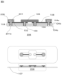
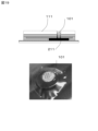
- FIG. 1 is a diagram showing an electrode sheet according to the first embodiment.
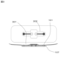
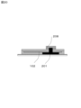
- FIG. 2 is a diagram showing an electrode sheet according to the second embodiment.
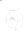
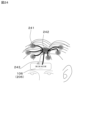
- FIG. 3 is a diagram showing the attachment of the electrode sheet to the forehead of the subject.
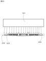
- FIG. 4 is a diagram showing an interference fit.
- FIG. 5 is a diagram showing a method of implementing the first embodiment on a subject.
- FIG. 6 is a diagram showing a method of implementing the third embodiment on a subject.
- FIG. 7 is a diagram showing a conventional mounting method.
- FIG. 8 is a diagram showing a conventional mounting method.
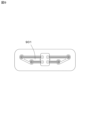
- FIG. 9 is a diagram showing an electrode sheet according to the fourth embodiment.
- FIG. 10 is a diagram showing an electrode sheet according to the fifth embodiment.
- FIG. 11 is a diagram showing an electrode sheet according to the sixth embodiment.
- FIG. 12 is a diagram showing an electrode sheet according to the seventh embodiment.
- FIG. 13 is a diagram showing the process of removing the formwork after printing the wiring member.
- FIG. 14 is a diagram showing a process of forming a through hole using a punch after printing a wiring member.
- FIG. 15 is a diagram showing an electrode sheet according to the eighth embodiment.
- FIG. 16 is a diagram showing a manufacturing process of an electrode sheet according to the eighth embodiment.
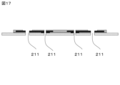
- FIG. 17 is a diagram showing a manufacturing process of an electrode sheet according to the eighth embodiment.
- FIG. 18 is a diagram showing a manufacturing process of an electrode sheet according to the eighth embodiment.
- FIG. 19 is a diagram showing an electrode according to the eighth embodiment.
- FIG. 20 is a diagram showing an electrode according to the ninth embodiment.
- FIG. 20 is a diagram showing an electrode according to the ninth embodiment.
- FIG. 21 is a diagram showing an electrode sheet according to the eighth embodiment.
- FIG. 22 is a diagram showing an electrode sheet according to the tenth embodiment.
- FIG. 23 is a diagram showing an electrode sheet according to the tenth embodiment.
- FIG. 24 is a schematic diagram of an electrode sheet according to the eleventh embodiment.
- FIG. 25 is a schematic diagram of fixing electrodes on an electrode sheet according to the eleventh embodiment.
- FIG. 26 is a schematic diagram of fixing the module or terminal of the electrode sheet according to the eleventh embodiment.
- This embodiment has a structure in which conductive electrodes and a sensor module that directly or indirectly extract electrical signals generated from a living body are brought into close contact with human skin.
- the electrodes and the sensor module are arranged and mounted on the same surface of the electrode sheet or on one side of the electrode sheet, and can be fixed with an adhesive sheet while the electrodes and the sensor module are in contact with the skin surface. Furthermore, by mounting on one side, it is possible to reduce the cost by reducing the amount of materials and the manufacturing process.
- a needle-like member 101 comprising at least one pair of electrodes that contacts a living body and receives a bioelectrical signal, a wiring member 102 that transmits the received bioelectrical signal voltage, and a wiring member 102 that transmits the received bioelectrical signal voltage.
- An electrode sheet 106 that has a connecting member 103 connected to a sensor module 105 that outputs to the outside, and integrates a needle member 101, a wiring member 102, an insulating film 108, a connecting member 103, a sheet member 104, and a sensor module 105.
- the adhesive sheet 107 on the top layer is used to support the bonding with the skin so that the needle member 101 and the sensor module 105 are in contact with the living body, and at least the wiring member, the sheet member, and the top layer
- the adhesive sheet is characterized by its stretchability and elasticity.
- two connecting members 103 protrude symmetrically from the sensor module.
- the voltage of the bioelectrical signal received from the needle member 101 is connected to each of these two connection members via the wiring member 102, and the sensor module receives the obtained voltage.
- the more the path from the needle-like member 101 to the sensor module in this reception is integrated with the skin of the living body, the more it will be possible to suppress the generation of noise due to shaking and wobbling of the sensor module caused by movements of the living body. can.
- the electrode sheet 106 is formed so that the tip of the needle-like member 101 and the sensor module 105 in FIG. 1 are located close to the skin surface.
- an adhesive sheet is pasted on the tip of the needle-like member 101 and the surface opposite to the sensor module 105 so as to cover the electrode sheet 106 and the sensor module 105 entirely.
- the area ratio of the adhesive sheet to the electrode sheet 106 and the sensor module 105 is such that when the area occupied by the electrode sheet 106 and the sensor module 105 is 1, the area of the adhesive sheet is preferably 5 to 6 or more. This realizes stable fixation of the electrode sheet 106 and the sensor module 105.
- the needle-like member 101 may already have conductivity itself, or the entire surface of the needle-like member may be coated with a conductive layer.
- the needle-like member 101 is arranged so that a needle-like projection (hereinafter simply referred to as a "needle”) can push against or puncture the patient's skin. Such pressure or puncture reduces the electrical resistance of the skin.
- the needle member 101 is arranged so that a needle having a cross section on the order of several tens of micrometers can puncture living tissue without causing much trauma.
- the needle-like member 101 has a support body 101a for arranging the needle.
- the needle member 101 preferably has a plurality of needles protruding above the support 101a, and preferably has a length ranging from 50 microns to 300 microns, and furthermore, the outer circumference of the needles is 10 microns. It may have an outer diameter range of from 250 microns to 250 microns.
- the length of the needle and the external shape range of the outer periphery of the needle depending on the method of fixing the needle-like member 101, the length of the needle may be insufficient. It is also possible to have an external shape range of the outer periphery of the needle of 250 microns or more.
- the needle of the needle-like member 101 can take various shapes and forms.
- the distal end may be pointed or non-pointed, and may have a beveled configuration, a parabolic configuration, a flat tip configuration, a pointed configuration, or a non-pointed configuration.
- the shape may be rounded, tapered and/or tapered conical.
- the needle-like members may be provided as a multidimensional array, as opposed to a device with a single needle or a single row of needles.
- the needle-like member 101 can include a combination of needle area, orientation, height, or other parameters.
- the larger the surface area of the conductive layer the larger the effective surface area as an electrode, which can reduce the electrical resistance of the skin.
- the needle-like member 101 is designed to easily penetrate the skin and reduce electrical resistance, it is possible to reduce the area of the conductive layer.
- the thickness of the conductive layer is preferably about 0.05 ⁇ m to 5 ⁇ m. If it is thinner than this, the conductivity will not be maintained, and if it is thicker than this, there is a concern that the adhesiveness with the base material will be impaired.
- the needle-like member 101 is made by known microfabrication processes by making small mechanical structures from metals, polymers, and other materials. These microfabrication processes are based on established methods used to make integrated circuits, electronic packages, and other microelectronic devices, supplemented with additional methods used in the microfabrication field.
- Microfabrication processes that can be utilized in manufacturing the needle member 101 disclosed herein include lithography, etching techniques such as wet etching, dry etching and photoresist removal, electroplating and electrodeless plating, and diffusion processes such as Boron diffusion, phosphorus diffusion, arsenic diffusion and antimony diffusion, ion implantation, film deposition such as evaporation (filament, electron beam, flash and shadowing step coverage), sputtering, chemical vapor deposition (CVD), epitaxy (vapor phase, liquid phase and molecular beams), electroplating, screen printing, lamination, stereolithography, laser machining and laser ablation (including projection ablation).
- lithography etching techniques such as wet etching, dry etching and photoresist removal, electroplating and electrodeless plating, and diffusion processes such as Boron diffusion, phosphorus diffusion, arsenic diffusion and antimony diffusion, ion implantation, film deposition such as evaporation (filament, electron beam, flash and shadow
- the needle-like member 101 is made from conductive materials in the following ranges, including, but not limited to, metals, ceramics, semiconductors, organics, polymers, and composites.
- Preferred materials include nickel-titanium alloys, medical grade stainless steel, gold, titanium, nickel, iron, gold, platinum, tin, chromium, copper, alloys of these or other materials, silicon, silicon dioxide, capacitive carbon. carbon), graphite and polymers.
- a specific example of the polymer is highly conductive PEDOT:PSS (a composite consisting of poly(3,4-ethylenedioxythiophene) (PEDOT) and polystyrene sulfonic acid (PSS)).
- PEDOT:PSS a composite consisting of poly(3,4-ethylenedioxythiophene) (PEDOT) and polystyrene sulfonic acid (PSS)
- Ideal embodiments use materials that are both electrically conductive and biocompatible, such as nickel titanium alloys, titanium or medical grade stainless steel,
- a molded product of the needle-like member 101 can be produced by using the needle-like member 101 as an original plate and using a transfer molding technique using a copy plate.
- a transfer molding technique using a copy plate.
- thermal transfer molding, soft lithography molding, or injection molding may be used.
- by coating with the above conductive material it is also possible to obtain a needle-like member whose base material is a transfer molded product and whose surface is conductive. It is desirable that the needle-like member molded product obtained by transfer molding be selected from polymers that ensure biosafety when puncturing the skin. For example, polycarbonate, polystyrene, epoxy resin, polyethylene, polymethyl methacrylate, polyglycolic acid, etc. are used.
- the needle-like member 101 may comprise a shaft having a circular cross-section when viewed vertically, or this cross-section may be non-circular.
- the cross-section of the needle-like member may be polygonal (e.g., star-shaped, square, triangular, circular), oval or another symmetrical or asymmetrical shape, or even the needle-like member may be pseudo-pyramidal.
- the structure may include a body (a shape similar to a pyramid, such as a pyramid with a sharper tip or a partially concave shape), a cone, a polyhedron, a pyramid, or a prism.
- the needle may be oriented perpendicularly or at another angle to the support 101a.
- the needles are oriented perpendicular to the support 101a such that the density of needles per unit area of the support 101a is high.
- the needle may include different orientations of the needle, different heights, or combinations of other parameters.
- the lengths of the needles may or may not be the same between the needles.
- the needles may have a certain needle density (number of needles within a certain area). For example, a useful range of needle-to-needle separation is 100 to 1400 microns, more preferably 100 to 400 microns.
- the outer diameter and needle length mentioned above are also important, and in combination with the separation distance, it is critical whether the needle actually pierces the stratum corneum of the skin.
- the needles have a needle density of at least about 10 needles/cm 2 , more preferably at least about 200-2000 needles/cm 2 . These needle densities also contribute to uniformity of the depth at which the skin is punctured by the needles.
- the needle-like member may be flexible in order to be able to conform to the contours of the biological barrier to which it is applied, such as the skin.
- Penetration into the skin is assumed to be limited by variations in the mounting surface of biological electrodes.
- the surface of human skin is not flat due to wrinkles and body hair, which may prevent puncture into the skin. This is the reason why it is restricted.
- Flexibility may mean distortion of 0.1 mm or more and 5 mm or less when a load of 4 kgf is applied to both ends of a 1 cm range.
- the conductive member used in this embodiment is positioned as being inexpensive, whereas the needle-like member is expensive.
- the needle-like member directly punctures the skin to acquire bioelectrical signals, but the conductive member is loaded onto the electrode sheet 106 in place of the needle-like member to create an electrolyte between the skin and the conductive member.
- Bioelectrical signals are acquired by interposing a conductive gel containing .
- the conductive member is made from conductive materials in the following ranges, including, but not limited to, metals, ceramics, semiconductors, organics, polymers, and composites.
- Preferred materials include nickel-titanium alloys, medical grade stainless steel, gold, titanium, nickel, iron, gold, platinum, tin, chromium, copper, alloys of these or other materials, silicon, silicon dioxide, capacitive carbon. carbon), graphite and polymers.
- a specific example of the polymer is highly conductive PEDOT:PSS (a composite consisting of poly(3,4-ethylenedioxythiophene) (PEDOT) and polystyrene sulfonic acid (PSS)).
- PEDOT:PSS a composite consisting of poly(3,4-ethylenedioxythiophene) (PEDOT) and polystyrene sulfonic acid (PSS)
- Ideal embodiments use materials that are both electrically conductive and biocompatible, such as nickel titanium alloys, titanium or medical grade stainless steel, silver/
- the structure of the wiring member related to the biological electrode of this embodiment will be explained in detail.
- the wiring member in this embodiment is formed using a screen printing method.
- This screen printing method is explained in detail in the specification and drawings of Japanese Patent Application No. 2021-105169, which is an earlier application by the present applicant.
- this embodiment may be realized by a printing method other than the screen printing method such as a rotary screen printing method, or a screen printing method other than the printing method shown in the specification of Japanese Patent Application No. 2021-105169.
- This screen printing method which is used to form the wiring member of the biological electrode of this embodiment, is good at printing with a high aspect ratio (thick printing thickness), and is based on the specification of the earlier application, Japanese Patent Application No. 2021-105169. This was achieved by using a technology that simultaneously fills the via and prints high aspect ratio wiring, which is the characteristic shown in Figure 2.
- the wiring member that can be used in this embodiment is a wiring member that is printed with a coating agent containing a mixture of filler and binder (main ingredient) and an additive that is incompatible with the main solvent, which is the binder solvent, as printing ink. be.
- inorganic fillers and organic fillers can be used in the wiring member.
- Inorganic fillers are classified into metals and nonmetals.
- Organic fillers mainly refer to polymeric compositions.
- Metals include noble metals and base metals.
- noble metals include gold, silver, platinum, and palladium
- base metals include iron, copper, nickel, aluminum, lead, zinc, tin, tungsten, molybdenum, tantalum, magnesium, cobalt, These include bismuth, cadmium, titanium, zirconium, antimony, manganese, beryllium, chromium, germanium, vanadium, gallium, hafnium, indium, niobium, rhenium, and thallium.
- Gold, silver, and copper are particularly useful in this embodiment.
- Nonmetals refer to elements other than the metals mentioned above.
- reactive nonmetals include hydrogen, carbon, nitrogen, oxygen, fluorine, phosphorus, sulfur, chlorine, bromine, selenium, iodine, Astatine, noble gases such as helium, neon, argon, krypton, xenon, and radon; semimetals with nonmetallic chemical properties such as boron, silicon, germanium, arsenic, antimony, and tellurium.
- inorganic fillers include substances in which multiple elements are chemically bonded, such as calcium carbonate, silica, carbon black, graphite, carbon nanotubes, alumina, aluminum nitride, boron nitride, beryllia, barium titanate, lead zirconate titanate. , ferrite, CMC (carboxymethyl cellulose), titanium oxide, glass beads, magnesium oxide, hydrotalcite, barium sulfate, titanium oxide, zinc oxide, iron oxide, calcium oxide, magnesium oxide, zeolite, calcium oxide, magnesium oxide, etc. It will be done.
- the polymer compound that is an organic filler is a linear polymer formed into a thread or chain by chemically bonding the inorganic filler in a one-dimensional structure through a chemical reaction such as addition polymerization, condensation polymerization, addition condensation, or covalent bond.
- a chemical reaction such as addition polymerization, condensation polymerization, addition condensation, or covalent bond.
- Inorganic fillers used in wiring materials are inorganic compounds in which copper, silver, silicon, etc. are chemically bonded with oxygen, hydrogen, carbon, etc., and are based on metal atoms that have electrical and thermal conductivity. In particular, those having a siloxane bond are preferred.
- the organic filler is a polymer having urethane bonds such as polyurethane, which is usually produced by polyaddition of a compound having an isocyanate group and a hydroxyl group, and has a bond mediated by urethane (-NH CO O-), or urethane resin.
- Synthetic resins made of polymers of acrylic esters or methacrylic esters such as urethane rubber acrylic resins, polymer compounds with amide bonds (the same bonds as proteins), and highly conductive PEDOT:PSS (poly(3) , 4-ethylenedioxythiophene) (PEDOT) and polystyrene sulfonic acid (PSS).
- the shape of the filler is spherical, flat, acicular, polygonal, etc., and the particle size is preferably from 0.1 ⁇ m to several tens of ⁇ m.
- Binders that can be used for wiring members include thermosetting resins, photocuring resins, and thermoplastic resins.
- Thermosetting resins are in a state before chemical reactions such as addition polymerization, condensation polymerization, addition condensation, and covalent bonding of the organic fillers, and a relatively low-molecular substance is heated to form a polymer three-dimensional crosslinked structure (network structure). ), such as phenolic resins, amino resins, unsaturated polyester resins, epoxy resins, and silicone rubbers.Once hardened, they do not soften again even when heated.
- Thermosetting resins have various reaction temperature ranges from room temperature to high temperatures, and react through addition polymerization, condensation polymerization, addition condensation, covalent bonding, etc.
- the main raw material for elastomers such as silicone rubber is polyorganosiloxane (silicone polymer) whose polymer skeleton (main chain) is siloxane bonds (Si-O-) in which silicon atoms and oxygen atoms are arranged alternately.
- Si-O- siloxane bonds
- the curing temperature for HTV is 140°C or higher, for LTV it is 40-140°C, and for RTV it is 0-40°C, but due to diversification, the boundary between HTV and LTV has disappeared, and it is simply heat curing and room temperature curing. They are often classified by type.
- HCR Solid millable type
- liquid type liquid type
- LSR Liquid Silicone Rubber
- RTV Reactive silicone Rubber
- a linear gum with a degree of polymerization of about 5,000 to 10,000 is used, whereas in the case of liquid silicone rubber (LSR, RTV), the main component is a linear polymer with a degree of polymerization of about 100 to 2,000.
- LSR liquid silicone rubber
- it can be classified into peroxide curing, addition reaction curing, and condensation reaction curing, depending on the crosslinking mechanism.
- a photocurable resin is a resin that is polymerized and cured by light of a specific wavelength.
- the binder refers to a thermosetting resin, a photocurable resin, a thermoplastic resin, etc. before chemical reaction or fixation or adhesion as described above.
- Binders used in wiring members are mainly composed of thermoplastic polyurethane elastomer, which is a block copolymer with urethane bonds, thermoplastic polyurethane, thermosetting urethane elastomer, polyester, acrylic rubber, polypropylene, and polyester. Rubber elastic and porous resins such as acrylic elastomers and thermoplastic elastomers containing block copolymers of methyl methacrylate and butyl acrylate can be used.
- Siloxane refers to a state in which silicon (Si) and oxygen (O) are alternately bonded to form a polymer, and is the main skeleton of silicone called siloxane bonds.
- a silicone elastomer having a siloxane compound as its backbone is highly effective in making the electrode flexible or stretchable.
- the ink for pattern wiring printing that can form the wiring member that can be used in this embodiment is defined based on a completely different concept from the printing ink used for general printing purposes.
- Typical printing inks are used by mixing binders contained in printing inks with small differences in solubility parameters (hereinafter abbreviated as SP values). Since two components with a small difference in SP value are easy to mix (high solubility), it is possible to ensure ease of handling during printing, smoothness of the printed matter, adhesion to the printed material, etc.
- additives with a large difference in SP value are used for the inorganic filler or organic filler and/or binder contained in the printing ink. By doing so, it becomes possible to cause the additive to ooze out as a lubricant due to the filling pressure.
- a silicone elastomer having a skeleton of a siloxane compound is used as a binder for printing ink
- a water-soluble solvent since it is water-insoluble, it is preferable to use a water-soluble solvent as an additive.
- the elastomer has rubber elasticity and porous properties, the water-soluble solvent penetrates into the pores and becomes impregnated.
- the impregnated additives ooze out due to the pressure and shear applied to the printing ink, forming a film on the interface between the plate and the printing ink, and acting as a lubricant to improve slipperiness. is likely to occur.
- a conductive material such as silver or carbon is used as a filler
- a silicone polymer is used as a binder
- a main solvent is a linear siloxane such as dimethylsiloxane or dodecamethylpentasiloxane.
- cyclic siloxanes such as octadecamethylcyclononasiloxane), n-undecane, and other solvents containing aliphatic hydrogen as the main ingredient, and additives may be added.
- the binder is water-insoluble
- the additive is water-soluble.
- the printing ink used in this embodiment will be explained using a mixture of rubber (binder) and oil (additive) as an example.
- rubber (binder) and oil (additive) are mixed, the rubber swells. This is a phenomenon in which oil enters between the molecules of rubber. If the oil (additive) mixes easily with the rubber (binder), it will swell; if it does not, it will not swell. This means that it oozes out onto the rubber surface under conditions such as compression.
- the binder of the printing ink is water-insoluble
- adding a water-soluble solvent additive will prevent substances with different polarities and substances with large differences in SP value from mixing with each other.
- a condition is formed in which the additive, which is a water-soluble solvent, oozes out onto the surface of the ink.
- a water-insoluble solvent is used as an additive. Then, by the same mechanism as described above, the water-insoluble solvent oozes out onto the surface of the printing ink and acts as a lubricant.
- non-water-soluble solvents and water-soluble solvents can be used as the main solvent and additives used in the printing ink.
- fillers and solvents contained in printing inks used in printing methods compositions containing a compound represented by the following structural formula (1) (excluding monohydroxystearic acid) are Can be used.
- solvent examples include n-heptane (SP value: 7.3), 2-(2-ethoxyethoxy)ethyl acetate (SP value: 9.0), and ethylene glycol monoethyl ether acetate (SP value: 8.
- the SP value is only a reference for the solvent to be selected, and what is important is determining whether it is water-insoluble or water-soluble, and the combination of adding a solvent that is the exact opposite of the main solvent.
- water-soluble liquids that are class 4 hazardous materials.
- Class 4 dangerous goods are flammable liquids. They are further divided into (a) those that dissolve in water (water-soluble) and (b) those that do not dissolve in water (water-insoluble).
- a water-soluble liquid is one that maintains a uniform appearance when mixed with the same volume of pure water at 1 atm and 20°C.
- a water-insoluble liquid is something other than a water-soluble liquid; When mixed, it separates into two layers. If the specific gravity of the liquid is lower than water, a water-insoluble layer will be formed above the water layer, and if the specific gravity is higher than water, a water-insoluble layer will be formed below the water layer. In the case of water-soluble liquids, when mixed, the layers become uniform without separating. Although some substances are slightly soluble in water, such as diethyl ether, a special flammable substance, and ethyl acetate, a class 1 petroleum, they are classified as water-insoluble by definition.
- water-soluble solvents include 2-(2-ethoxyethoxy)ethyl acetate (SP value: 9.0), ethylene glycol monoethyl ether acetate (SP value: 8.8), n-propanol (SP value: 11.8), 1,2,5,6-tetrahydrobenzyl alcohol (SP value: 11.3), diethylene glycol ethyl ether (SP value: 10.9), 3-methoxybutanol (SP value: 10.9), propylene glycol monomethyl ether (SP value: 10.2), ⁇ -butyrolactone (SP value: 9.9), propylene glycol-n-propyl ether (SP value: 9.8), dipropylene Glycol methyl ether (SP value: 9.7), lactic acid ethyl acetate (SP value: 9.6), ⁇ -caprolactone (SP value: 9.6), tripropylene glycol methyl ether (SP value: 9.4), Tripropylene glycol-
- the water-insoluble solvents include undecane (SP value: 15.8), decane (SP value: 15.8), dodecane (SP value: 16.0), triacetin (SP value: 10.2), and cyclopentanone ( SP value: 10.0), cyclohexanone (SP value: 9.9), propylene glycol-n-butyl ether (SP value: 9.7), 1,4-butanediol diacetate (SP value: 9.6), 3-methoxybutyl acetate (SP value: 8.7), propylene glycol diacetate (SP value: 9.6), 1,3-butylene glycol diacetate (SP value: 9.5), dipropylene glycol-n- Propyl ether (SP value: 9.5), 1,6-hexanediol diacetate (SP value: 9.5), dipropylene glycol-n-butyl ether (SP value: 9.4), cyclohexanol acetate (SP value:9.2), diethylene glycol mono
- the filler When the total weight of the filler and binder contained in the printing ink used in this embodiment is 100 parts, the filler may be 50 to 99.9 parts. Specifically, fillers, silver pastes, copper pastes, etc. used for printing purposes, etc. may be used as the main ingredient.
- the additive of the printing ink in the range of 0.1 part to 50 parts when the total weight of the filler and binder contained in the coating agent is 100 parts.
- the printing ink used in this embodiment may contain a compatible solvent that has good affinity with the binder.
- a compatible solvent makes it possible to ensure adhesion, electrical conductivity, conductivity, etc. between the inorganic filler or organic filler and binder mixture (main ingredient) and the printing substrate. This is because slipperiness can be obtained while maintaining these properties. If the amount added is outside the above range, the chemical bonds of the elastomer, which is the main ingredient, will be damaged or separated, resulting in physical brittleness, making printing difficult. Even if it can be printed, it may lose its elasticity or significantly lose its electrical conductivity or thermal conductivity.
- the printing ink used in this embodiment has the effect that the lubricant in the coating agent oozes out due to the pressure applied to the printing ink when sweeping with a squeegee. Therefore, the peeling of the coating agent from the mask interface is promoted and the coating agent is transferred to the base material without causing cohesive failure, resulting in a wiring member with a substantially rectangular cross-sectional shape and an opposing side surface standing up almost vertically.
- the cross-sectional shape does not necessarily have to be substantially rectangular and the opposing side surfaces do not necessarily have to stand up substantially vertically.
- sheet member A flexible sheet or stretchable sheet used as a sheet member on which a wiring pattern of a wiring member according to the present embodiment is printed will be described.
- Flexible sheets or stretchable sheets that can be used in this embodiment include OPP (biaxially oriented polypropylene), CPP (unoriented polypropylene), HDPE (high density polyethylene), MDPE (medium density polyethylene), LDPE (low density polyethylene), L-LDPE (linear low-density polyethylene), PET (polyethylene terephthalate), PEN (polyethylene naphthalate), O-NY (nylon), PA (polyamide), EVAC (EVA resin), PVC (polyvinyl chloride), SAN (AS resin), ABS (ABS resin), PMMA (methacrylic resin), PVAL (polyvinyl alcohol), PVDC (vinylidene chloride resin), PC (polycarbonate), POM (acetal resin), PBT (polybutylene terephthalate), PTFE (fluororesin), PF (phenolic resin), MF (melamine resin), UF (urea resin), PUR (polyurethane), EP (epoxy resin), UP (
- the sheet member 104 can arbitrarily take the form of a single layer or a laminated film of two or more layers.
- a urethane-based film may be selected as the printing surface layer, and a PET film, for example, may be selected for the lower layer to provide rigidity.
- a primer or an adhesive layer may be sandwiched between the urethane film and the PET film to improve adhesion.
- other types of sheets, primers, and adhesive layers may be optionally laminated on the lower layer of the PET film.
- a silicone-based film may be selected as the printing surface layer, and a PET film, for example, may be selected as the lower layer to provide rigidity.
- a primer or an adhesive layer may be sandwiched between the silicone film and the PET film to improve adhesion.
- other types of sheets, primers, and adhesive layers may be optionally laminated on the lower layer of the PET film.
- a protective film may be provided in consideration of handling properties such as a base film required during film formation of the sheet member and stain resistance during printing, etc.
- the material of the base film may be PET film, polyethylene film, etc. That's fine, there are no limitations.
- through-holes such as vias or through-holes for inserting and fixing the needle-like member 101, the conductive member 201, and the connecting member 103 are made in the single-layer or laminated sheet member using a hole punch or punch. Drill holes where necessary. This hole is formed by injecting a wiring member into the hole and forming a conductive via or through hole, for example, by the screen printing method of the present invention, which will be described later.
- the opening diameter of this via or through hole must have an interference tendency with respect to the diameter of the portion of the needle member 101, the conductive member 201, and the connecting member 103 to be inserted and fixed in the via or through hole.
- the fit tolerance should be changed from zero tolerance, which is a "medium fit,” to a negative tolerance, which is an "tight fit.” This eliminates the wobbling of the needle member 101, the conductive member 201, and the connecting member 103, making it possible to ensure strong conductivity. In addition to this state, it is also possible to apply a conductive adhesive to further improve reliability.
- the diameter of the via or through hole may be a diameter obtained by subtracting a ratio of -99.9% from -0% to the diameter of the fixed portion of the needle member 101, the conductive member 201, and the connecting member 103, and further It may be from 0% to -40%, or even from -0% to -15%.
- the tips of the needle-like member 101, the conductive member 201, and the connecting member 103 may be shaped like needles and pierced.
- connection member 103 of the sensor module can be directly inserted into a via or through hole that ensures conductivity, and therefore materials can be saved, so that the unit price of a disposable patch can be reduced. can.
- the electrolyte-containing conductive gel used in this embodiment is a highly conductive gel that exhibits flexibility, plasticity, and adhesiveness in an electrolyte solution in which at least one of an amino acid, an organic salt, and an inorganic salt is dissolved. It is made by adding molecular materials and solidifying it into a gel-like state. Polymer materials that exhibit flexibility, plasticity, and adhesiveness are those that have a glass transition point below living temperature and a melting point above living temperature, such as acrylic and polyurethane materials. Conceivable. Furthermore, "living temperature” in this embodiment means a temperature in the range of 0 degrees to 40 degrees.
- the insulating film that can be used in this embodiment is desirably made of a material that does not undergo strength deterioration, deformation, melting, deterioration, etc. during the desired usage time.
- a sheet made of a polyester resin such as polyethylene terephthalate, polybutylene terephthalate, polyethylene naphthalate, ethylene-terephthalate-isophthalate copolymer, polyarylate, etc., and preferably a non-stretched sheet can be used.
- resin sheets made of polyvinyl fluoride, polyvinylidene fluoride, polytetrafluoroethylene, fluororesins such as ethylene-tetrafluoroethylene copolymers, polyimide resins, and RTV silicone rubber. UV-cured silicone rubber and the like can also be used.
- insulating films can be bonded in a desired area by methods such as thermal fusion, dry lamination, and spray coating. Alternatively, it is also possible to coat the desired area by printing methods such as silk screen, gravure printing, flexographic printing, offset printing, and roll transfer printing.
- resin binder of the ink used for example, acrylic resin, polyester resin, polyimide resin, silicone resin, etc. can be used. Note that the thickness of the insulating coating is usually preferably about 20 to 300 ⁇ m.
- connection member that can be used in this embodiment is basically connected to or incorporated into the sensor module.
- the material is made from conductive materials in the following ranges, including, but not limited to, metals, ceramics, semiconductors, organics, polymers, and composites.
- Preferred materials include nickel-titanium alloys, medical grade stainless steel, gold, titanium, nickel, iron, gold, platinum, tin, chromium, copper, alloys of these or other materials, silicon, silicon dioxide, capacitive carbon. carbon), graphite and polymers.
- a specific example of the polymer is highly conductive PEDOT:PSS (a composite consisting of poly(3,4-ethylenedioxythiophene) (PEDOT) and polystyrene sulfonic acid (PSS)).
- PEDOT:PSS a composite consisting of poly(3,4-ethylenedioxythiophene) (PEDOT) and polystyrene sulfonic acid (PSS)
- Ideal embodiments use materials that are both electrically conductive and biocompatible, such as nickel titanium alloys, titanium or medical grade stainless steel, silver/sil
- connection member may be loaded and fixed inside the sensor module 105, or the connection member may be fixed on the electrode sheet 106 side and inserted into the sensor module 105 side for connection. good. There are no particular limitations on the external shape, function, etc. of the sensor module 105.
- the electrode sheet of this embodiment when the electrode sheet of this embodiment is attached to a human's forehead, it may have the function of wirelessly transmitting and receiving between the sensor module side and a mobile phone, PC, radio wave transmitting/receiving base station, etc.
- the sensor module 105 may be connected to a mobile phone, a PC, a measuring device, etc. by wire. In the former case, it may include a two-dimensional or three-dimensional antenna for transmitting and receiving radio waves.
- the antenna may be placed along the wall of the module housing or embedded within it.
- the antenna may be located within the module, or an antenna separately printed on an electrode sheet may be used, connected to the sensor module 105 via a connecting member if necessary.
- This embodiment may also include connection with a plurality of electrodes through a connecting member as shown in FIG. 9 (connection with two or more, for example, four electrodes, connection with an external antenna, etc.).
- the sensor module may include a signal generator and one or more bioamplifiers that generate a signal between two or more of the electrodes (e.g., typically between 1 Hz and 10 GHz, 1 kHz and 10 MHz). between 5 kHz and 1 MHz, at multiple frequencies, swept across different frequencies, etc.), the bioamplifier is configured to provide one configured to capture one or more signals.
- a processor, gate array, digital signal processor, or associated microcircuit is configured to analyze the captured signals to determine the bioimpedance of nearby tissue.
- the bioamplifier is configured to capture bioelectrical signals (e.g., EKG (ElektroKardioGramm), HR (HeartRate), EMG (ElectroMyoGraphy), EOG (ElectroOculoGraphy), EEG (ElectroEncephaloGraphy), ERG (ElectroRetinoGraphy), etc.) from the electrodes. be done.
- the sensor module may also include a power source (eg, a primary battery, a secondary battery, an energy harvesting system, etc.). In particular, it is better to use a power source that can be replaced when replacing the electrode sheet and reusing the sensor module, such as a thin flexible battery.
- each module may be a self-powered device.
- the sensor module may include a processor and an internal power source.
- a wired connection as shown in FIG. 6 may be used, and the functions of the sensor module 105 can be reduced, and functions such as the antenna and power source can be supplied from the outside, so the total weight of the electrode sheet 106 can be reduced. becomes lighter and reduces the discomfort of the subject.
- Electrodes sheets for acquiring bioelectrical signals have been constructed by arranging the electrode sheet and the sensor module separately, and connecting the sensor module on top of the electrode sheet.
- an adhesive sheet is attached to the top layer in a manner that completely envelops the electrodes and sensor module.
- the sensor module is located on the same surface on which the needle-like member 101 that extracts bioelectrical signals from the electrode sheet, the conductive member 201, and the wiring member 102 are formed, and even when the wire is taken out from the sensor module, Similarly, noise can be reduced by fixing wires with adhesive sheets.
- the needle-like member 101 and the sensor module come into direct contact with the living body surface, and the moment of force caused by the positional relationship between the electrode and the sensor module is minimized.
- the basic size of the adhesive sheet member is about 150 mm in width and 50 mm in length, even if it is large, and its shape can be changed arbitrarily.
- the adhesive sheet can be printed with conductive ink, and it is also possible to print patterns for electromagnetic shielding or decoration purposes, or to attach metal foil.
- the pressure of the needle-like member or the conductive member on the skin increases.
- This adhesive sheet has a base material/adhesive composition, and the adhesive is applied to the electrode and module fixing sides.
- the thickness of the base material/adhesive composition is preferably 10 ⁇ m or more and 200 ⁇ m or less.
- the base material contains a urethane resin, and may contain at least one selected from the group consisting of an ether polyurethane resin, an ester polyurethane resin, and a carbonate polyurethane resin, and has a thickness of 5 ⁇ m or more and 30 ⁇ m or less. It is preferable that
- the adhesive is made of synthetic resin, preferably a urethane adhesive.
- the thickness of the adhesive layer is preferably 5 ⁇ m or more and 25 ⁇ m or less.
- the tensile elongation at break in the laminated adhesive sheet is 130% or more, and the tensile stress at 100% elongation is preferably 10 to 100 MPa, and more preferably 10 to 30 MPa. It has the effect of appropriately following the unevenness of the surface, expansion and contraction of the biological surface, etc. Further, it is preferable that the moisture permeability is 2000 g/m 2 ⁇ day or more, and within this range, there is a transpiration effect due to skin respiration, water vapor, and sweating of the living body.
- the adhesive sheet may be porous. Furthermore, cuts or holes may be opened at arbitrary positions around the sensor module or around the electrode sheet for the purpose of further improving air permeability or releasing air around the sensor module or electrode sheet.
- the adhesive sheet may be made of silicone-based material as long as the same effect can be obtained.
- the test speed was set to 300 mm/min, the distance between gauge lines L0 was set to 25 mm, and the initial distance L between grips was set to 80 mm.
- the tensile strain at break was calculated as the tensile elongation at break.
- the nominal tensile strain at break was calculated as the tensile elongation at break.
- the measurement was performed on a laminate formed only from the base material and the adhesive.
- the most distinctive feature of this embodiment is that an adhesive sheet is placed on the top layer, but instead of this top layer adhesive sheet, a sheet coated with photocurable resin is used to tightly connect the skin, electrodes, and sensor module. It has also been found that dry fixing by curing by irradiation with light in a state in which the material has been dried is also effective in solving the problems of the present invention.
- the electrode sheet is attached to the subject's skin to cover the entire sensor module, but instead of the adhesive sheet 107, a sheet in which a photocurable resin is applied to a porous film or a PET film is used.
- Photocurable resins are photopolymerizable resins such as bisphenol A-glycidyl methacrylate adduct (Bis-GMA), triethylene glycol dimethacrylate (TEGDMA), urethane dimethacrylate (UDMA), other diacrylates, triacrylates, It may be a composite material (composite resin) that is a mixture of a mixture, an inorganic filler such as quartz, silicon nitride, or glass, or an organic composite filler including an organic substance, and the light source for curing is a halogen lamp, xenon lamp, UV lamp, or visible light LED. , UV light LED, etc. may be used.
- a sheet in which a photocurable resin is applied to a porous film or a PET film is attached to the forehead, head, top of the head, torso, hands, and feet, and a light source is applied for several seconds to several tens of seconds.
- a light source is applied for several seconds to several tens of seconds.
- the thin film-like photocurable resin can be crushed with fingertips, and the electrode sheet can be removed without much pain during peeling.
- Electrode sheet ⁇ Electrode sheet>
- the electrode sheet according to this embodiment will be described using a plurality of embodiments. However, it goes without saying that the present invention is not limited to these embodiments.
- components that are the same or equivalent to those already described are designated by the same reference numerals, and their explanations will be simplified or omitted.
- FIG. 1 is a diagram showing an electrode sheet according to the first embodiment. The contents of the first embodiment will be described below in the order of manufacture.
- the base material used in the first embodiment was the one shown in FIG. 1 in which a silicone sheet 104a was attached as an upper layer, an adhesive layer 104b was attached as a middle layer, and a PET film 104c was attached as a lower layer.
- the bonded silicone sheet 104a, adhesive layer 104b, and PET film 104c will be collectively referred to as a sheet member 104.
- this cylinder and metal plate will be collectively referred to as the formwork.
- a metal mold is used, but engineering plastics such as polypropylene, polyethylene, polyimide, epoxy resin, acrylic resin, silicone, fluororesin, urethane resin, and UV-cured resin may also be used.
- the technology shown in the specification of Japanese Patent Application No. 2021-105169 prints a wiring pattern using a conductive coating agent on a sheet to be printed that has via holes extending toward the front side and the back side. At the same time, this technology injects a conductive coating agent into the via hole (hole) and connects the front side and back side of the sheet with the conductive coating agent, forming a sheet that has conductivity on the front and back sides of the sheet. be.
- the above printing creates electrical conductivity in the gap between the high aspect ratio wiring, the through hole with a diameter of 3 mm punched to insert the needle member 101 and the connecting member 103, and the cylinder with a diameter of 2.5 mm formed in the formwork.
- the paste was printed and filled at the same time.
- FIG. 13 is a diagram showing the process of removing the formwork after printing the wiring member.
- FIG. 14 is a diagram showing a process of forming a through hole using a punch after printing a wiring member.
- a cylindrical film of the conductive coating agent is formed on the wall surface of the through hole, which facilitates electrical connection when the needle-like member 101 and the connecting member 103 are loaded with a tight fit in the subsequent process. You can get the following effect.
- the needle-shaped member 101 is loaded, but since it is essential that the support 101a has a large diameter and tightly fits into the through hole filled with the conductive coating agent, the support 101a must have a diameter of 3 mm.
- the needle-like member 101 was selected.
- the electrode sheet 106 and the support 101a of the needle-like member 101 were completely integrated by suctioning the needle tip of the needle-like member 101 with suction tweezers and loading it vertically into the through-hole with a tight fit. Confirmed by checking continuity using a tester.
- the electrode sheet other than the sensor module 105 and the connecting member 103 is completed.
- the two connecting members 103 were connected to the two remaining through holes of the electrode sheet 106 with a tight fit without any force.
- An interference fit refers to a state in which the hole diameter 401 of the through hole and the shaft diameter 402 of the support body 101a of the needle-like member 101 are inserted in a relationship such that shaft diameter>hole diameter in the embodiment shown in FIG.
- the elastic force of the electrode sheet 106, which is an elastic body, and the conductive wiring member 102 of this embodiment can provide the effect that the needle member 101 and the connecting member 103 are firmly fixed by tight fit.
- This relationship is generally expressed as "interference” or “fitting tolerance,” but the difference in the diameters of both the shaft and the hole, or the fitting tolerance, varies depending on the material of the sheet, so it cannot be specified here.
- the hole diameter is set to be 0 to minus (smaller) than the diameter of the support 101a.
- the above electrode sheet was evenly pasted on the center of the subject's forehead 301, and the protective film on the surface of the adhesive sheet was peeled off.
- the adhesive sheet was placed as the top layer of this embodiment.
- a gap 302 formed at the interface between the forehead 301, the sensor module 105, the electrode sheet 106, and the adhesive sheet 107 may be formed to some extent.
- the sense of unity with forehead 301 was maintained.
- the form in which the needle of the needle-like member 101 stably sticks is such that the sensor module 105 is placed at the center of gravity of the adhesive sheet, that is, the center, and the electrode sheet 106 is wired symmetrically with respect to the center of gravity (center) of the sensor module.
- the member 102 takes the shape of spread wings, and the needle-like member 101 is loaded at a position 2 cm or 3 cm farther from the connecting member 103 of the sensor module 105 than 1 cm, so that the adhesive sheet generated around the sensor module 105 is Since the influence of the gap 302 can be avoided, the needle can be inserted stably. Therefore, the height from the attachment surface of the sensor module 105 is 2 mm or 1 mm rather than 3 mm, so that the gap 302 between the adhesive sheets becomes smaller and the needle of the needle member 101 stably sticks therein.
- the quality of the signal that can be obtained by the connection member 103 was evaluated.
- the objective is to see how close the accuracy of the contact impedance transmitted from the needle-like member 101 to the connection member 103 of this embodiment can be compared to that of a medical needle electrode used in a medical field.
- the measured resistance values for the medical needle electrode were a maximum resistance of 2.2K ⁇ (0.5Hz), a minimum resistance of 0.7K ⁇ (30KHz), and a resistance value of 1.0K ⁇ around 100Hz.
- the electrode sheet 106 of this embodiment exhibited a maximum resistance value of 6.2 K ⁇ (0.5 Hz), a minimum resistance value of 3.5 K ⁇ (30 KHz), and a resistance value of 4.2 K ⁇ near 100 Hz.
- the results obtained using the two-terminal method using three types of electrodes showed that the needle electrode had the lowest resistance value, and the electrode sheet of this embodiment was slightly larger than the needle electrode, but much larger than the gel electrode. It was small. Although the center frequency of bioelectrical signal measurement is approximately 1 Hz to 200 Hz, the electrode sheet of this embodiment had a much lower resistance value up to around 100 Hz than the gel electrode.
- the electrode sheet of this embodiment was found to be an effective electrode.
- FIG. 2 is a diagram showing an electrode sheet according to the second embodiment. The contents of the second embodiment will be described below in the order of manufacture.
- the base material used in the second embodiment was the one shown in FIG. 2 in which a silicone sheet 104a was attached as an upper layer, an adhesive layer 104b was attached as a middle layer, and a PET film 104c was attached as a lower layer.
- the bonded silicone sheet 104a, adhesive layer 104b, and PET film 104c will be collectively referred to as a sheet member 104.
- a metal cylinder with a diameter of 2.5 mm and a metal plate with the lower bottom surface of the cylinder joined to a flat surface were superimposed so that the center of the through hole with a diameter of 3 mm coincided with the center of the cylinder with a diameter of 2.5 mm.
- the height of this cylinder matches the height of the through hole in the sheet member 104.
- the combination of this cylinder and metal plate will be collectively referred to as the formwork.
- the material of the metal plate may be stainless steel, nickel, copper, aluminum, iron oxide, graphite, etc.
- the above printing creates conductivity in the gap between the high aspect ratio wiring, the through hole with a diameter of 3 mm punched to insert the conductive member 201 and the connecting member 103, and the cylinder with a diameter of 2.5 mm formed in the formwork.
- the paste was printed and filled at the same time.
- FIG. 13 is a diagram showing the process of removing the formwork after printing the wiring member.
- FIG. 14 is a diagram showing a process of forming a through hole using a punch after printing a wiring member.
- the conductive member 201 is loaded, but it is essential that the support 201a has a large diameter and tightly fits into the through hole filled with the conductive paste. Member 201 was selected.
- the conductive member 201 was suctioned with suction tweezers and vertically loaded into the through hole with a tight fit, and it was confirmed that the electrode sheet 206 and the support 201a of the conductive member 201 were completely integrated.
- the electrode sheet other than the sensor module 105 and the connecting member 103 is completed.
- the two connecting members 103 were connected to the remaining two through-holes of the electrode sheet 206 in the same manner as in the first embodiment with a tight fit.
- a conductive gel 208 was attached so as to cover the entire exposed surface of the conductive member 201.
- the above electrode sheet was evenly pasted on the center of the subject's forehead 301, and the protective film on the surface of the adhesive sheet was peeled off.
- the adhesive sheet was placed as the top layer of this embodiment, We have completed a method that envelops the entire electrode sheet and sensor module.
- an impedance measuring device (NF Circuit Design Co., Ltd. ZM2376) is connected to the sensor module with a conductive wire.
- the bioelectrode device of this embodiment produced almost no noise and had a maximum resistance of 6.2 K ⁇ (0.5 Hz) and a minimum resistance of 3.5 K ⁇ (30 KHz). ), the resistance value near 100Hz was 4.2K ⁇ .
- extreme noise was generated and measurements were impossible.
- FIGS. 5 and 6 A method of mounting the first embodiment and the third embodiment on a subject is shown in FIGS. 5 and 6, and a conventional mounting method is shown in FIGS. 7 and 8. From the above content, it can be said that even if the chicken (thigh) is replaced with a human body, the effects of this embodiment are superior to the conventional mounting method.
- FIG. 9 shows an embodiment in which bioelectrical signals of the electrode sheet according to the first embodiment are simultaneously acquired from two or more locations, that is, from multiple locations.
- the electrode also serves as an electrode for performing electrical treatment by flowing current while simultaneously acquiring bioelectrical signals.
- the basic manufacturing method is the same as the first embodiment, but in the first embodiment, four through holes were formed, so two pairs of the needle-like member 101 and the connecting member 103 were formed.
- the number of through holes is eight, and four pairs of the needle member 101 and the connecting member 103 are formed.
- This embodiment can also be applied to the second embodiment and the third embodiment. For example, it becomes possible to flow current using a needle-like member based on bioelectrical signals obtained from the conductive gel and conductive member according to the second embodiment. In that case, the wired method according to the third embodiment You can make it even more effective.
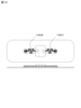
- the wiring member 102 may have a meandering pattern as shown in FIG.
- it may be a horseshoe-shaped continuous wiring that snakes regularly.
- the wiring member 102 is formed on a flexible and stretchable base material and used as an electrode sheet, if there is a possibility that noise may be introduced due to the subject's movement, undulations, expansion/contraction, vibration of the attachment surface, etc., use the meandering pattern shown in FIG. 10.
- 1001 may be formed.
- slits 1002 may be cut in the electrode sheet at arbitrary locations in the meandering pattern for more flexible handling.
- the sheet member 104 may be a single layer or a laminated sheet with two or more layers.
- a structure using a PET base material was mainly shown in a three-layer structure.
- This PET base material has a tensile strength of 48 MPa to 73 MPa, an elongation at break of 30 to 300%, and a tensile modulus of elasticity of 2,800 MPa to 4,200 MPa, which is stronger than elastomer materials such as silicone sheets, according to ASTM standard D638. . Therefore, by using such a material for a part of the sheet member 104, it is possible to obtain the advantage that delicate bioelectrical signals such as brain waves can be obtained without much distortion.
- the first to fifth embodiments are designed to obtain such effects.
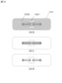
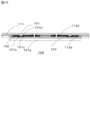
- the sheet member 104 can be constructed by laminating an adhesive sheet 107 with a film (elastomer material 1101) such as a silicone sheet, or directly applying an elastomer to the adhesive sheet 107 by screen printing or the like.
- a film elastomer material 1101
- the adhesion with the adhesive sheet 107 tends to be weak due to surface energy, so a primer or adhesive 1102 is applied to the lower layer of the film to strengthen the adhesion with the adhesive sheet 107. may be adopted.
- the primer may or may not be applied to the adhesive sheet 107 in advance.
- the adhesive sheet 107 takes the form of being attached to the subject's skin in a manner that covers the entire electrode sheet and sensor module, as in the above embodiments. All or part of the bioelectrical signal data obtained by the sensor module is transmitted by radio waves, but the radio waves transmitted from the sensor module, radio waves entering from the outside, and electromagnetic waves affect the electrode sheets 106 and 206. It is also assumed that
- a solid or mesh pattern can be printed on the adhesive sheet 107 using conductive ink using an inkjet method so as to cover at least the sheet member 104 without covering a part of the sensor module.
- Solid is a printing term that refers to a state in which 100% of the entire surface is coated.
- the mesh pattern is based on consideration of permeability, moisture permeability, design, etc.
- conductive ink may be used to print a decorative image such as a pattern, a skin color that looks like it is integrated with the skin, etc. on the adhesive sheet 107.
- These printing methods are not limited to inkjet, but may also use offset printing, screen printing, gravure printing, flexo printing, dispensers, and 3D printers.
- metal foil such as copper or aluminum may be attached, which has a similar effect. This is what is called an electromagnetic shield.
- FIG. 12 shows the mesh pattern on the adhesive sheet.
- the mesh pattern 1202 may be printed on the entire surface 1210 of the adhesive sheet without covering a part 1201 of the sensor module, or may be printed on the entire surface 1210 of the adhesive sheet to cover only the electrode sheet, or only the wiring member portion.
- a covering shape 1212 may also be used.
- mesh patterns there is a tendency for mesh patterns to be as inconspicuous as possible, and the surface obtained by configuring fine lines with a line width of 30 ⁇ m or less, more preferably 15 to 20 ⁇ m or less, and a line thickness of 3 ⁇ m or less in a lattice shape with a pitch of 300 ⁇ m to 500 ⁇ m.
- the resistivity is 40 ⁇ / ⁇ or less, and more preferably the surface resistivity is 1.2 ⁇ / ⁇ or less.
- both the electrode sheets 106 and 206 are loaded into the vertical through-holes with tight fit, and the electrode sheets 106 and the support 101a of the needle-like member 101 and the conductive member 201 are completely separated.
- One method is to ensure conductivity by integrating the support 201a and the connection member 103, but another method to ensure conductivity is to integrate the support 201a and the connection member 103 into one body.
- 101b and the lower plane 101c are sandwiched between the wiring member 102 and the adhesive sheet 107 to ensure integration with the electrode sheet 106 and conductivity.
- ink containing silver, copper, or carbon filler, or a conductive polymer such as PEDOT/PSS may be used.
- an insulating film 112a is printed on a release film 111 except for a region 115 where a connecting member 103 is inserted in a later step.
- the wiring member 102 is printed thereon.
- the insulating film 112b is printed except for the area 114 where the needle-shaped member 101 will be inserted later. Drying and curing after printing in the above steps are performed as needed.
- holes 211 for inserting the needle-like member 101 and the connecting member 103 are penetrated with a hole punch.
- the needle-like member 101 is inserted into the hole 211 with the support 101a of the needle-like member 101 in contact with the wiring member 102 as shown in FIG. 18(a).
- a conductive adhesive may be applied to the contact portion and its surroundings.
- the adhesive sheet 107 is attached to the entire structure including the release film 111.
- a separate film 107a is bonded to this adhesive sheet 107.
- FIG. 19 shows that when the needle-like member 101 in this embodiment peels off the release film 111, it is exposed from the hole 211, and the needle-like member 101 is firmly attached and fixed to the electrode sheet 106 separated from the release film 111.
- This figure shows that the needle-like member 101 is firmly sandwiched between the printed wiring member 102 and the adhesive sheet 107, and only the needle portion of the needle-like member 101 is exposed through the hole 211, creating a sense of unity.
- the electrode sheet 106 is formed by integrating the release film 111, the insulating film 112a, the wiring member 102, the insulating film 112b, the needle member 101, the adhesive sheet 107, and the separate film 107a. Furthermore, depending on the convenience of handling and packaging capacity, the sheet may be divided into arbitrary shapes and sizes instead of a large-area sheet.
- the connecting member 103 of the sensor module 105 When the subject inserts the connecting member 103 of the sensor module 105 into the hole 211 of the electrode sheet 106, the connecting member 103 may hit the separate film 107a and be difficult to insert. Therefore, the presence of the needle hole 515 allows the tip of the connecting member 103 to break a part of the separate film 107a using the needle hole 515 of the separate film 107a as a trigger, allowing it to come into closer contact with the hole 211. Become. This makes the conduction from the connecting member 103 to the needle member 101 more reliable.
- the advantage of the needle holes 515 is that in the manufacturing process of the adhesive sheet 107, the adhesive sheet 107 and the separate film 107a are placed on a continuous line, such as roll-to-roll, using a rolling roll that is embossed with many pointed needles.
- the needle hole 515 can be easily formed by passing the needle through a device that has been prepared.
- the size and number of the needle holes 515 can be changed arbitrarily, and an opening in the shape of a circle or a polygon may be made instead of the needle hole.
- FIG. 20 shows an example in which a conductive member 201 is used instead of the needle-like member 101 in FIG. 19 shown in the eighth embodiment. This structure enables the acquisition of biological signals.
- an insulating film 112a is printed on the release film 111, except for the area 115 where the connecting member 103 is inserted in a later step, in the same manner as the procedure shown in the eighth embodiment.
- the wiring member 102 is printed thereon.
- an insulating film 112b is printed except for a region 114 where a conductive member 201 in place of the needle member 101 will be inserted later. Drying and curing after printing in the above steps are performed as needed.
- a hole 211 for inserting the conductive member 201 instead of the needle-like member 101 and the connecting member 103 is penetrated with a hole punch.
- the conductive member 201 is brought into contact with the wiring member 102 as shown in FIG.
- the conductive member 201 is inserted inside the hole 211.
- the wiring member 102 and the conductive member 201 are electrically connected, but if necessary, a conductive adhesive may be applied to the contact portion and its surrounding area.
- the release film 111 is peeled off once before being supplied to the subject, and the conductive gel 208 containing electrolyte is removed. The process of pasting and re-pasting the release film is added.
- the adhesive sheet 107 takes the form of being attached to the subject's skin in a manner that covers the entire electrode sheet 106 and sensor module 105 as in the above embodiments.
- a sheet 221 in which a photocuring resin 222 is applied to a porous film or a PET film 223 may be used.
- the photocurable resin 222 is a photopolymerizable resin, and includes bisphenol A-glycidyl methacrylate adduct (Bis-GMA), triethylene glycol dimethacrylate (TEGDMA), urethane dimethacrylate (UDMA), and other diacrylates and triacrylates. , mixtures, inorganic fillers such as quartz, silicon nitride, and glass, and composite materials (composite resins) containing organic composite fillers including organic materials may be used.
- the light source for curing may be a halogen lamp, xenon lamp, UV lamp, or visible light. LEDs, UV light LEDs, etc. may also be used.
- a sheet 221 in which a porous film or PET film 223 is coated with a photocuring resin 222 is pasted on the forehead, head, top of the head, body, hands, and feet.
- the photocurable resin hardens, adheres, and holds the hair 232, thereby creating an anchor effect and achieving dry application.
- the light source 231 may be pressed against the sheet 221 to irradiate the sheet 221, so that the photocurable resin 222 preferably becomes a thin film.
- UV-A wavelength 315 to 400 nm
- the necessary integrated light amount is preferably in the range of 1 mJ/cm 2 to 4000 mJ/cm 2 , more preferably in the range of 1 mJ/cm 2 to 2000 mJ/cm 2 , but ultimately an appropriate amount of light is selected in consideration of the effect on the human body. do.
- the thin film-like photocurable resin can be crushed with fingertips, and the electrode sheet can be removed without much pain during peeling.
- the tenth embodiment can be applied to fixing a bioelectrode device. This is particularly effective when the needle-like member is used as an electrode.
- the electrode sheet 106 and the sensor module 105 are entirely covered, but by using the photocurable resin of the tenth embodiment, a needle-like shape is formed as shown in FIGS. 24 to 26.
- the fixing 241 of the member and the fixing 242 of the sensor module 105 or the terminal 226 can be done separately using a sheet 221 in which a photocuring resin 222 is applied to a porous film or a PET film 223 in the same manner as in the tenth embodiment.
- the eleventh embodiment is applicable not only to the tenth embodiment but also to fixation of a bioelectrode device. This is particularly effective when the needle-like member is used as an electrode.
- the tenth embodiment or the eleventh embodiment can be attached to the forehead, head, top of the head, neck, trunk, hands, feet, etc., and can also be used as an electrode sheet for electrical therapy.
- a biological electrode device comprising:
- a biological electrode device comprising: The electrode sheet includes a sheet member that supports the electrode, the wiring member, the sensor module, and the connection member. Biological electrode device.
- the biological electrode device according to aspect 1 or aspect 2,
- the electrode is a needle-like member that is brought into contact with a living body and receives a bioelectrical signal.
- Biological electrode device is a needle-like member that is brought into contact with a living body and receives a bioelectrical signal.
- the biological electrode device according to aspect 1 or aspect 2,
- the electrode sheet has at least a pair of conductive gels that are brought into contact with a living body and receive bioelectrical signals,
- the electrode is a conductive member that receives bioelectrical signals from the conductive gel.
- Biological electrode device is a conductive member that receives bioelectrical signals from the conductive gel.
- a biological electrode device according to any one of aspects 1 to 4,
- the sensor module wirelessly transmits a signal related to the bioelectrical signal to the outside.
- Biological electrode device wirelessly transmits a signal related to the bioelectrical signal to the outside.
- a biological electrode device according to any one of aspects 1 to 4,
- the sensor module has a conductor that outputs a signal related to a bioelectrical signal to the outside,
- the adhesive sheet is capable of fixing a part of the conductive wire to a living body, Biological electrode device.
- a biological electrode device according to any one of aspects 1 to 6, comprising: The electrodes are arranged in a plurality of pairs and receive bioelectrical signals at a plurality of locations. Biological electrode device.
- a biological electrode device according to any one of aspects 1 to 7, The electrodes are arranged in a plurality of pairs, and include electrodes for receiving bioelectrical signals and electrodes for electrical treatment that flow current through the living body. Biological electrode device.
- a biological electrode device according to any one of aspects 1 to 8, comprising: the wiring member has a meandering pattern; Biological electrode device.
- a biological electrode device according to any one of aspects 2 to 9, the wiring member has a meandering pattern; the sheet member has slits at arbitrary locations in the meandering pattern; Biological electrode device.
- connection member is fixed to a portion where the wiring member is coated on the wall surface of the hole drilled in the sheet member with a fit tolerance of “medium fit” or “tight fit”; Biological electrode device.
- a biological electrode device according to any one of aspects 1 to 10, The electrode is held between the wiring member and the adhesive sheet, and is fixed in such a manner that a protruding portion of the electrode is exposed through a hole made in the wiring member. Biological electrode device.
- a biological electrode device according to any one of aspects 1 to 10 and 13, The connecting member is inserted and fixed into a hole drilled in the wiring member, Biological electrode device.
- a biological electrode device according to any one of aspects 1 to 14, The adhesive sheet is porous. Biological electrode device.
- a biological electrode device according to any one of aspects 1 to 16, The adhesive sheet has metal foil attached to it. Biological electrode device.
- (Aspect 18) at least one pair of electrodes for receiving bioelectrical signals; a wiring member that transmits the received bioelectrical signal; a sensor module that outputs signals related to bioelectrical signals to the outside; a connecting member that connects the transmitted bioelectrical signal to the sensor module; an electrode sheet having a photocurable resin that can be attached to a living body in a manner that covers the electrode sheet;
- a biological electrode device comprising:
- Conductive gel 211... Hole, 221... Sheet, 222... Photocurable resin, 223... Porous Film or PET film, 226...Terminal, 231...Light source, 232...Hair, 241...Fixing of needle-like member, 242...Fixing of sensor module or terminal, 243...Wiring, 301...Forehead, 302...Gap, 401...Hole diameter , 402... Shaft diameter, 515... Needle hole, 901... Through hole, 1001... Meandering pattern, 1002... Slit, 1101... Elastomer material, 1102... Primer or adhesive, 1201... Part of sensor module, 1202... Mesh pattern, 1210...Full surface, 1211...Shape that covers only the electrode sheet portion, 1212...Shape that covers only the wiring member portion.
Landscapes
- Health & Medical Sciences (AREA)
- Life Sciences & Earth Sciences (AREA)
- Engineering & Computer Science (AREA)
- Animal Behavior & Ethology (AREA)
- Veterinary Medicine (AREA)
- Public Health (AREA)
- Biomedical Technology (AREA)
- General Health & Medical Sciences (AREA)
- Surgery (AREA)
- Molecular Biology (AREA)
- Physics & Mathematics (AREA)
- Medical Informatics (AREA)
- Heart & Thoracic Surgery (AREA)
- Pathology (AREA)
- Biophysics (AREA)
- Computer Networks & Wireless Communication (AREA)
- Nuclear Medicine, Radiotherapy & Molecular Imaging (AREA)
- Radiology & Medical Imaging (AREA)
- Measurement And Recording Of Electrical Phenomena And Electrical Characteristics Of The Living Body (AREA)
- Electrotherapy Devices (AREA)
Abstract
Description
針状部材101は、針状部材自体が導電性を既に持っているものでもよいし、針状部材表面全面に導電層を被覆してもよい。
本実施形態に使用する導電性部材は、針状部材が高価であるとすると廉価な位置づけで使用する。針状部材は、皮膚に直接穿刺し、生体電気信号を取得するが、導電性部材は、針状部材の部分と置き換わる形で電極シート106に装填されて、皮膚と導電性部材の間に電解質を含んだ導電性ゲルを介在させて、生体電気信号を取得する。
本実施形態の生体用電極に係る配線部材の構造について詳細に説明する。本実施形態における配線部材は、スクリーン印刷法を使用して形成される。本スクリーン印刷法は、本出願人による先願である特願2021-105169号の明細書および図面において詳細に説明されている。ただし、ロータリースクリーン印刷法などのスクリーン印刷法以外の印刷法、特願2021-105169号の明細書に示す印刷法以外のスクリーン印刷法で本実施形態を実現しても良い。
R1-CH2-R2 (1)
(式中、R1はモノヒドロキシアルキル基を示し、R2はカルボキシル基(C(=O)OH)又はアミド基(C(=O)NH2)を示す)
本実施形態に係る配線部材の配線パターンを印刷する対象となるシート部材に用いるフレキシブルシートまたはストレッチャブルシートについて説明する。
本実施形態に使用する電解質を含んだ導電性ゲルは、少なくとも、アミノ酸、有機塩、及び、無機塩のいずれかが溶解された電解質溶液に、柔軟性、可塑性、及び、粘着性を発揮する高分子材料を加えてゲル状に固めものである。柔軟性、可塑性、及び、粘着性を発揮する高分子材料としては、生活温度以下のガラス転移点、及び、生活温度以上の融点を有するものが用いられ、例えば、アクリル系やポリウレタン系のものが考えられる。また、本実施の形態における「生活温度」とは、0度~40度の範囲の温度を意味する。
本実施形態に使用できる絶縁膜は、所望の使用時間の間に強度劣化、変形、溶融、変質、等の生じない材料で構成することが望ましい。例えば、ポリエチレンテレフタレート、ポリブチレンテレフタレート、ポリエチレンナフタレート、エチレン-テレフタレート-イソフタレート共重合体、ポリアリレート等のポリエステル樹脂からなるシートで、好ましくは、無延伸シートを用いることができる。或いは、ポリフッ化ビニル、ポリフッ化ビニリデン、ポリ4フッ化エチレン、エチレン-4フッ化エチレン共重合体等のフッ素樹脂、ポリイミド樹脂等からなる樹脂シート、RTVシリコーンゴム。UV硬化シリコーンゴム等も使用できる。
本実施形態に使用できる接続部材は、基本的にはセンサーモジュールに接続するもしくは組み込まれている。
本実施形態に使用するセンサーモジュール105は、接続部材がセンサーモジュール105内に装填、固定されていてもよく、あるいは電極シート106側に固定し、センサーモジュール105側に、挿入して接続しても良い。センサーモジュール105の外形、機能等については、特に限定はしない。
本実施形態で最も特徴的なのが最上層に粘着シートを配置することである。
[引張破断伸度]
JIS K7127:1999(ISO 527-3:1995)の「プラスチック-引張特性の試験方法-第3部:フィルム及びシートの試験条件」、および、JIS K7161-1:2014(ISO 527-1:2012)の「プラスチック-引張特性の求め方-第1部:通則」に準拠する方法によって、引張破断伸度を測定した。引張破断伸度の測定に際して、粘着シートをダンベル形状(試験片タイプ5)に型抜きし、引張試験機((株)島津製作所製、AGS-X 5kN)を用いて引張破断強度を測定した。試験速度を300mm/minに設定し、標線間距離L0を25mmに設定し、初めのつかみ具間距離Lを80mmに設定した。試験片が降伏点を有しない場合には、引張破壊ひずみを引張破断伸度として算出した。一方で、試験片が降伏点を有する場合には、引張破壊呼びひずみを引張破断伸度として算出した。なお、引張破断伸度を測定する際には、基材と粘着剤とのみから形成される積層体に対して、測定を実施した。
引張破断伸度を測定するときと同様に、JIS K7127:1999(ISO 527-3:1995)の「プラスチック-引張特性の試験方法-第3部:フィルム及びシートの試験方法」に準拠し、試験片を準備した。そして、JIS K7161-1:2014(ISO 527-1:2012)の「プラスチック-引張特性の求め方-第1部:通則」に準拠して、ひずみが100%に達したときの応力として100%伸び引張応力を算出した。
本実施形態で最も特徴的なのが最上層に粘着シートを配置することであるが、この最上層の粘着シートの替わりに、光硬化樹脂を塗布したシートを用い、皮膚と電極とセンサーモジュールを密着させた状態で光照射によって、硬化させることによりドライで固定する手段も本発明の課題解決に有効であることが判った。電極シート、センサーモジュール全体を覆う形で、被験者の皮膚に貼り付ける形態をとるが、粘着シート107の替わりに光硬化樹脂を多孔質フィルムまたはPETフィルムに塗布したシートを用いる。
以下に、本実施形態例に係る電極シートについて、複数の実施形態により説明する。ただしこれらの実施形態により本発明が限定されるものではないことは言うまでもない。また、図面の記載において、既述の構成と同一又は同等のものについては同一の符号を付し、その説明を簡略又は省略する。
図1は、第1実施形態に係る電極シートを示した図である。以下、第1実施形態について、製造の順にしたがって、その内容を説明する。
しまりバメとは、図4の実施形態において貫通孔の穴径401と針状部材101の支持体101aの軸径402との関係が軸径>穴径の関係で挿入されている状態を言う。本実施形態の弾性体である電極シート106および導電性のある配線部材102の弾性力によって、しまりバメによって強固に針状部材101および接続部材103が固定される効果を得ることができる。この関係を一般的に「しめしろ」、「はめあい公差」と表現することがあるが、軸と穴の両方の直径の差つまりはめあい公差は、シートの材質等によって変化する為、ここでは特定できなが、穴径は支持体101aの直径より0からマイナス(小さい)にする。
図2は、第2実施形態に係る電極シートを示した図である。以下、第2実施形態について、製造の順にしたがって、その内容を説明する。
第1実施形態において、接続部材103で取得できる信号の品質評価を皮付き鶏肉(もも)をつかって実施した内容に引き続き、インピーダンス測定装置(エヌエフ回路設計社ZM2376)を導線でセンサーモジュールへつなげる有線仕様として、導線を1Hz、振幅20cmで揺すってみたところ、本実施形態の生体電極装置は、殆どノイズが入らず抵抗最大値6.2KΩ(0.5Hz)、抵抗最小値3.5KΩ(30KHz)、100Hz付近の抵抗値4.2KΩを示した。逆にセンサーモジュールを外に接続し、導線を同様に揺すると極端なノイズが入り計測不能となった。
図9は、第1実施形態に係る電極シートの生体電気信号を2つ以上、つまり複数の箇所を同時に取得する実施形態を示す。または、生体電気信号を取得しながら、同時に電流を流す電気治療をする電極も兼ねた実施形態を示す。基本的な製作方法は第1実施形態と変わらないが、第1実施形態は貫通孔を4か所開けたことで、針状部材101と接続部材103の対が2本形成されていたのに対し、本実施形態は貫通孔の数を8個開けて針状部材101と接続部材103の対が4本形成されている。当然、さらに多くの貫通孔を開けることも可能で、これにより、例えば脳波計測点を、多点にしても良い。ただし、多点にすればするほど、電極シートに占める配線面積が増大する為、所々に、電極シートの配線と配線の間に測定に使わない貫通孔901を開けても良い。これにより被験者の皮膚と電極シートの界面の蒸れによる不快感を軽減することができる。
第1実施形態から第4実施形態までにおいて、図10の様に配線部材102は、そのパターンが蛇行しても良い。例えば規則正しく蛇行する馬蹄形の連続配線でも良い。フレキシブルおよびストレッチャブルな基材に配線部材102を形成し、電極シートとした場合、被験者の動きや貼付け面の起伏、伸縮、振動などによりノイズが入る可能性がある場合は、図10の蛇行パターン1001を形成してもよい。また、より柔軟に対応する様に蛇行パターンの任意の場所において電極シートにスリット1002を刻んでもよい。
第1実施形態から第5実施形態までにおいて、シート部材104は、単層または2層以上の貼合シートでもよい。第1実施形態から第5実施形態まででは主に3層構成でPET基材を使用した構成を示した。このPET基材は、一般的性能としてASTM規格D638において引張り強さ48MPaから73MPa、破断時伸び30~300%、引張弾性率2800MPaから4200MPaといったシリコーンシート等のエラストマー材料に比べ強じんな剛性をもっている。従って、このような素材をシート部材104の一部に使用することによって、脳波などの繊細な生体電気信号をあまり歪ませる事なく取得できる長所を得ることができる。第1実施形態から第5実施形態まではそのような効果も得ることを想定した構成となっている。
第1実施形態から第6実施形態までにおいて、粘着シート107は、上記実施形態の通り、電極シート、センサーモジュール全体を覆う形で、被験者の皮膚に貼り付ける形態をとる。センサーモジュールで得られた生体電気信号のすべてのデータもしくは一部のデータを電波で発信するわけであるが、センサーモジュールから発信する電波、外から侵入する電波、電磁波が電極シート106、206に影響することも想定される。
第1実施形態から第7実施形態までは、電極シート106、206共に垂直な貫通孔にしまりバメで装填して、完全に電極シート106と針状部材101の支持体101aや導電性部材201の支持体201a、接続部材103を一体化することで、導電性を確保する方法であるが、もう一つの導電性を確保する方法として、図15に示す針状部材101の支持体101aの上部平面101bと下部平面101cの部分を配線部材102と粘着シート107の層で挟み込む形で電極シート106との一体化および導電性の確保をする。ここでいう配線部材は、銀、銅、カーボンフィラーを含むインキやPEDOT・PSSなどの導電性高分子を使用してもよい。
図20は、第8実施形態で示した、図19の針状部材101の代わりに、導電性部材201を用いたもので、針状部材101ではなく電解質を含んだ導電性ゲル208を介した生体信号の取得を可能とした構造である。
第1実施形態から第9実施形態までにおいて、粘着シート107は、上記実施形態の通り、電極シート106、センサーモジュール105全体を覆う形で、被験者の皮膚に貼り付ける形態をとるが、図22に示すように粘着シート107の替わりに光硬化樹脂222を多孔質フィルムやPETフィルム223に塗布したシート221を用いても良い。
第1実施形態から第10実施形態は、電極シート106、センサーモジュール105全体を覆う形であるが、第10実施形態の光硬化樹脂を使うことで、図24ないし図26に示すように針状部材の固定241と、センサーモジュール105またはターミナル226の固定242とを別々に光硬化樹脂222を多孔質フィルムやPETフィルム223に塗布したシート221を使って、第10実施形態の要領で固定できる。
第10実施形態または第11実施形態は、額、頭部、頭頂部、首、胴体、手、足などに装着し、電気治療の電極シートとしても使用できる。
生体電気信号を受信する少なくとも一対の電極と、
受信した生体電気信号を伝達する配線部材と、
生体電気信号に関連する信号を外部に出力するセンサーモジュールと、
伝達した生体電気信号を前記センサーモジュールに接続する接続部材と、
を有する電極シートと、
前記電極シートを覆う形で生体に貼り付け可能な粘着シートと、
を備える生体用電極装置。
態様1の生体用電極装置であって、
前記電極シートは、前記電極と前記配線部材と前記センサーモジュールと前記接続部材とを支持するシート部材を有する、
生体用電極装置。
態様1または態様2の生体用電極装置であって、
前記電極は、生体に接触させ生体電気信号を受信する針状部材である、
生体用電極装置。
態様1または態様2の生体用電極装置であって、
前記電極シートは、生体に接触させ生体電気信号を受信する少なくとも一対の導電性ゲルを有し、
前記電極は、前記導電性ゲルから生体電気信号を受信する導電性部材である、
生体用電極装置。
態様1ないし態様4のいずれか一つの生体用電極装置であって、
前記センサーモジュールは、生体電気信号に関連する信号を外部に無線送信する、
生体用電極装置。
態様1ないし態様4のいずれか一つの生体用電極装置であって、
前記センサーモジュールは、生体電気信号に関連する信号を外部に出力する導線を有し、
前記粘着シートは、前記導線の一部を生体に固定可能である、
生体用電極装置。
態様1ないし態様6のいずれか一つの生体用電極装置であって、
前記電極は、複数対配置され、複数個所の生体電気信号を受信する、
生体用電極装置。
態様1ないし態様7のいずれか一つの生体用電極装置であって、
前記電極は、複数対配置され、生体電気信号を受信する電極と生体に電流を流す電気治療用の電極とを有する、
生体用電極装置。
態様1ないし態様8のいずれか一つの生体用電極装置であって、
前記配線部材は、蛇行パターンを有する、
生体用電極装置。
態様2ないし態様9のいずれか一つの生体用電極装置であって、
前記配線部材は、蛇行パターンを有し、
前記シート部材は、蛇行パターンの任意の場所にスリットを有する、
生体用電極装置。
態様2ないし態様10のいずれか一つの生体用電極装置であって、
前記電極は、前記シート部材に開けられた穴の壁面に前記配線部材が被覆された箇所に、はめあい公差「中ばめ」または「しまりばめ」で固定されている、
生体用電極装置。
態様2ないし態様11のいずれか一つの生体用電極装置であって、
前記接続部材は、前記シート部材に開けられた穴の壁面に前記配線部材が被覆された箇所に、はめあい公差「中ばめ」または「しまりばめ」で固定されている、
生体用電極装置。
態様1ないし態様10のいずれか一つの生体用電極装置であって、
前記電極は、前記配線部材と前記粘着シートとの間に保持される形かつ前記配線部材に開けられた穴より前記電極の突出部分が露出する形で固定されている、
生体用電極装置。
態様1ないし態様10、態様13のいずれか一つの生体用電極装置であって、
前記接続部材は、前記配線部材に開けられた穴に挿入、固定されている、
生体用電極装置。
態様1ないし態様14のいずれか一つの生体用電極装置であって、
前記粘着シートは、多孔質である、
生体用電極装置。
態様1ないし態様15のいずれか一つの生体用電極装置であって、
前記粘着シートは、導電性インクによる印刷が施されている、
生体用電極装置。
態様1ないし態様16のいずれか一つの生体用電極装置であって、
前記粘着シートは、金属箔が貼り付けられている、
生体用電極装置。
生体電気信号を受信する少なくとも一対の電極と、
受信した生体電気信号を伝達する配線部材と、
生体電気信号に関連する信号を外部に出力するセンサーモジュールと、
伝達した生体電気信号を前記センサーモジュールに接続する接続部材と、
を有する電極シートと、
前記電極シートを覆う形で生体に貼り付け可能な光硬化樹脂と、
を備える生体用電極装置。
態様18に記載の生体用電極装置であって、
前記光硬化樹脂は、PETフィルムに塗布されている、
生体用電極装置。
態様18または態様19の生体用電極装置であって、
前記光硬化樹脂は、前記電極と前記センサーモジュールとを別々に生体に貼り付け可能である、
生体用電極装置。
態様18ないし態様20のいずれか一つの生体用電極装置であって、
前記電極の一部もしくはすべてを電気治療用の電極とする、
生体用電極装置。
態様1ないし態様21のいずれか一つの生体用電極装置であって、
前記センサーモジュールが前記電極シートの生体側の面に配置される、
生体用電極装置。
Claims (22)
- 生体電気信号を受信する少なくとも一対の電極と、
受信した生体電気信号を伝達する配線部材と、
生体電気信号に関連する信号を外部に出力するセンサーモジュールと、
伝達した生体電気信号を前記センサーモジュールに接続する接続部材と、
を有する電極シートと、
前記電極シートを覆う形で生体に貼り付け可能な粘着シートと、
を備える生体用電極装置。 - 請求項1に記載の生体用電極装置であって、
前記電極シートは、前記電極と前記配線部材と前記センサーモジュールと前記接続部材とを支持するシート部材を有する、
生体用電極装置。 - 請求項1に記載の生体用電極装置であって、
前記電極は、生体に接触させ生体電気信号を受信する針状部材である、
生体用電極装置。 - 請求項1に記載の生体用電極装置であって、
前記電極シートは、生体に接触させ生体電気信号を受信する少なくとも一対の導電性ゲルを有し、
前記電極は、前記導電性ゲルから生体電気信号を受信する導電性部材である、
生体用電極装置。 - 請求項1に記載の生体用電極装置であって、
前記センサーモジュールは、生体電気信号に関連する信号を外部に無線送信する、
生体用電極装置。 - 請求項1に記載の生体用電極装置であって、
前記センサーモジュールは、生体電気信号に関連する信号を外部に出力する導線を有し、
前記粘着シートは、前記導線の一部を生体に固定可能である、
生体用電極装置。 - 請求項1に記載の生体用電極装置であって、
前記電極は、複数対配置され、複数個所の生体電気信号を受信する、
生体用電極装置。 - 請求項1に記載の生体用電極装置であって、
前記電極は、複数対配置され、生体電気信号を受信する電極と生体に電流を流す電気治療用の電極とを有する、
生体用電極装置。 - 請求項1に記載の生体用電極装置であって、
前記配線部材は、蛇行パターンを有する、
生体用電極装置。 - 請求項2に記載の生体用電極装置であって、
前記配線部材は、蛇行パターンを有し、
前記シート部材は、蛇行パターンの任意の場所にスリットを有する、
生体用電極装置。 - 請求項2に記載の生体用電極装置であって、
前記電極は、前記シート部材に開けられた穴の壁面に前記配線部材が被覆された箇所に、はめあい公差「中ばめ」または「しまりばめ」で固定されている、
生体用電極装置。 - 請求項2に記載の生体用電極装置であって、
前記接続部材は、前記シート部材に開けられた穴の壁面に前記配線部材が被覆された箇所に、はめあい公差「中ばめ」または「しまりばめ」で固定されている、
生体用電極装置。 - 請求項1に記載の生体用電極装置であって、
前記電極は、前記配線部材と前記粘着シートとの間に保持される形かつ前記配線部材に開けられた穴より前記電極の突出部分が露出する形で固定されている、
生体用電極装置。 - 請求項1に記載の生体用電極装置であって、
前記接続部材は、前記配線部材に開けられた穴に挿入、固定されている、
生体用電極装置。 - 請求項1に記載の生体用電極装置であって、
前記粘着シートは、多孔質である、
生体用電極装置。 - 請求項1に記載の生体用電極装置であって、
前記粘着シートは、導電性インクによる印刷が施されている、
生体用電極装置。 - 請求項1に記載の生体用電極装置であって、
前記粘着シートは、金属箔が貼り付けられている、
生体用電極装置。 - 生体電気信号を受信する少なくとも一対の電極と、
受信した生体電気信号を伝達する配線部材と、
生体電気信号に関連する信号を外部に出力するセンサーモジュールと、
伝達した生体電気信号を前記センサーモジュールに接続する接続部材と、
を有する電極シートと、
前記電極シートを覆う形で生体に貼り付け可能な光硬化樹脂と、
を備える生体用電極装置。 - 請求項18に記載の生体用電極装置であって、
前記光硬化樹脂は、PETフィルムに塗布されている、
生体用電極装置。 - 請求項18に記載の生体用電極装置であって、
前記光硬化樹脂は、前記電極と前記センサーモジュールとを別々に生体に貼り付け可能である、
生体用電極装置。 - 請求項18に記載の生体用電極装置であって、
前記電極の一部もしくはすべてを電気治療用の電極とする、
生体用電極装置。 - 請求項1または請求項18に記載の生体用電極装置であって、
前記センサーモジュールが前記電極シートの生体側の面に配置される、
生体用電極装置。
Priority Applications (4)
| Application Number | Priority Date | Filing Date | Title |
|---|---|---|---|
| CN202380039306.5A CN119212622A (zh) | 2022-05-10 | 2023-04-20 | 生物体用电极装置 |
| EP23803373.2A EP4523625A4 (en) | 2022-05-10 | 2023-04-20 | ELECTRODE DEVICE FOR LIVING BODY |
| JP2024520342A JPWO2023218891A1 (ja) | 2022-05-10 | 2023-04-20 | |
| US18/936,319 US20250057457A1 (en) | 2022-05-10 | 2024-11-04 | Electrode device for living body |
Applications Claiming Priority (4)
| Application Number | Priority Date | Filing Date | Title |
|---|---|---|---|
| JP2022077435 | 2022-05-10 | ||
| JP2022-077435 | 2022-05-10 | ||
| JP2022199715 | 2022-12-14 | ||
| JP2022-199715 | 2022-12-14 |
Related Child Applications (1)
| Application Number | Title | Priority Date | Filing Date |
|---|---|---|---|
| US18/936,319 Continuation US20250057457A1 (en) | 2022-05-10 | 2024-11-04 | Electrode device for living body |
Publications (1)
| Publication Number | Publication Date |
|---|---|
| WO2023218891A1 true WO2023218891A1 (ja) | 2023-11-16 |
Family
ID=88730205
Family Applications (1)
| Application Number | Title | Priority Date | Filing Date |
|---|---|---|---|
| PCT/JP2023/015730 Ceased WO2023218891A1 (ja) | 2022-05-10 | 2023-04-20 | 生体用電極装置 |
Country Status (5)
| Country | Link |
|---|---|
| US (1) | US20250057457A1 (ja) |
| EP (1) | EP4523625A4 (ja) |
| JP (1) | JPWO2023218891A1 (ja) |
| CN (1) | CN119212622A (ja) |
| WO (1) | WO2023218891A1 (ja) |
Cited By (2)
| Publication number | Priority date | Publication date | Assignee | Title |
|---|---|---|---|---|
| WO2026047837A1 (ja) * | 2024-08-27 | 2026-03-05 | Ntt株式会社 | アダプタ |
| WO2026070508A1 (ja) * | 2024-09-25 | 2026-04-02 | Toppanホールディングス株式会社 | 生体用電極装置 |
Families Citing this family (3)
| Publication number | Priority date | Publication date | Assignee | Title |
|---|---|---|---|---|
| JP2024100150A (ja) * | 2023-01-13 | 2024-07-26 | 新光電気工業株式会社 | 筋電センサ |
| CN120052831A (zh) * | 2025-04-28 | 2025-05-30 | 浙江大学 | 一种可穿戴式癫痫诊疗一体化装置及其使用方法 |
| CN121714272B (zh) * | 2026-02-25 | 2026-04-21 | 合肥工业大学 | 基于磁流变液刚性可调的神经探针及其制备方法 |
Citations (10)
| Publication number | Priority date | Publication date | Assignee | Title |
|---|---|---|---|---|
| US20040015058A1 (en) * | 1993-09-04 | 2004-01-22 | Motorola, Inc. | Wireless medical diagnosis and monitoring equipment |
| JP2008532596A (ja) * | 2005-03-09 | 2008-08-21 | クティセンセ アクティーゼルスカブ | マイクロ電子システムを内部に埋め込んだ三次元接着デバイス |
| KR101843162B1 (ko) * | 2017-11-30 | 2018-03-27 | 위덕대학교 산학협력단 | 근육통 완화를 위한 테이핑 시스템 및 테이핑 방법 |
| CN107892891A (zh) * | 2017-05-04 | 2018-04-10 | 南京诺邦新材料有限公司 | 一种用于医用电极片的导电压敏胶及其制备方法 |
| WO2019035420A1 (ja) * | 2017-08-16 | 2019-02-21 | 東洋紡株式会社 | 生体情報計測用の電極部材、生体情報計測装置、生体情報計測用衣服、生体情報計測用の電極部材の取り付け方法および生体情報計測方法 |
| WO2019188311A1 (ja) * | 2018-03-28 | 2019-10-03 | ニプロ株式会社 | 生体用電極パッド、生体信号処理装置およびそれらの組合せ |
| WO2020183356A1 (en) * | 2019-03-11 | 2020-09-17 | Nelson & Company S.R.L.S. | Integrated device for electromyography and electrotherapy |
| WO2020262403A1 (ja) * | 2019-06-27 | 2020-12-30 | ニプロ株式会社 | 生体用電極パッド付き収納ケースおよび生体用電極パッド付き収納ケースを備えた生体信号処理装置 |
| WO2021105169A1 (en) | 2019-11-26 | 2021-06-03 | Rhodia Operations | Liquid dispersion and powder of cerium based core-shell particles, process for producing the same and uses thereof in polishing |
| JP2021105169A (ja) | 2019-12-26 | 2021-07-26 | 三菱ケミカル株式会社 | 芳香族ポリシアヌレートの製造方法 |
-
2023
- 2023-04-20 WO PCT/JP2023/015730 patent/WO2023218891A1/ja not_active Ceased
- 2023-04-20 JP JP2024520342A patent/JPWO2023218891A1/ja active Pending
- 2023-04-20 EP EP23803373.2A patent/EP4523625A4/en active Pending
- 2023-04-20 CN CN202380039306.5A patent/CN119212622A/zh active Pending
-
2024
- 2024-11-04 US US18/936,319 patent/US20250057457A1/en active Pending
Patent Citations (10)
| Publication number | Priority date | Publication date | Assignee | Title |
|---|---|---|---|---|
| US20040015058A1 (en) * | 1993-09-04 | 2004-01-22 | Motorola, Inc. | Wireless medical diagnosis and monitoring equipment |
| JP2008532596A (ja) * | 2005-03-09 | 2008-08-21 | クティセンセ アクティーゼルスカブ | マイクロ電子システムを内部に埋め込んだ三次元接着デバイス |
| CN107892891A (zh) * | 2017-05-04 | 2018-04-10 | 南京诺邦新材料有限公司 | 一种用于医用电极片的导电压敏胶及其制备方法 |
| WO2019035420A1 (ja) * | 2017-08-16 | 2019-02-21 | 東洋紡株式会社 | 生体情報計測用の電極部材、生体情報計測装置、生体情報計測用衣服、生体情報計測用の電極部材の取り付け方法および生体情報計測方法 |
| KR101843162B1 (ko) * | 2017-11-30 | 2018-03-27 | 위덕대학교 산학협력단 | 근육통 완화를 위한 테이핑 시스템 및 테이핑 방법 |
| WO2019188311A1 (ja) * | 2018-03-28 | 2019-10-03 | ニプロ株式会社 | 生体用電極パッド、生体信号処理装置およびそれらの組合せ |
| WO2020183356A1 (en) * | 2019-03-11 | 2020-09-17 | Nelson & Company S.R.L.S. | Integrated device for electromyography and electrotherapy |
| WO2020262403A1 (ja) * | 2019-06-27 | 2020-12-30 | ニプロ株式会社 | 生体用電極パッド付き収納ケースおよび生体用電極パッド付き収納ケースを備えた生体信号処理装置 |
| WO2021105169A1 (en) | 2019-11-26 | 2021-06-03 | Rhodia Operations | Liquid dispersion and powder of cerium based core-shell particles, process for producing the same and uses thereof in polishing |
| JP2021105169A (ja) | 2019-12-26 | 2021-07-26 | 三菱ケミカル株式会社 | 芳香族ポリシアヌレートの製造方法 |
Non-Patent Citations (1)
| Title |
|---|
| See also references of EP4523625A4 |
Cited By (2)
| Publication number | Priority date | Publication date | Assignee | Title |
|---|---|---|---|---|
| WO2026047837A1 (ja) * | 2024-08-27 | 2026-03-05 | Ntt株式会社 | アダプタ |
| WO2026070508A1 (ja) * | 2024-09-25 | 2026-04-02 | Toppanホールディングス株式会社 | 生体用電極装置 |
Also Published As
| Publication number | Publication date |
|---|---|
| US20250057457A1 (en) | 2025-02-20 |
| JPWO2023218891A1 (ja) | 2023-11-16 |
| EP4523625A4 (en) | 2025-05-14 |
| CN119212622A (zh) | 2024-12-27 |
| EP4523625A1 (en) | 2025-03-19 |
Similar Documents
| Publication | Publication Date | Title |
|---|---|---|
| US20250057457A1 (en) | Electrode device for living body | |
| Li et al. | E-tattoos: toward functional but imperceptible interfacing with human skin | |
| Kim et al. | Advances in soft and dry electrodes for wearable health monitoring devices | |
| Zhang et al. | Fully organic compliant dry electrodes self-adhesive to skin for long-term motion-robust epidermal biopotential monitoring | |
| Mondal et al. | Wearable sensing devices for point of care diagnostics | |
| US20250000419A1 (en) | Skin-mountable electronic devices and methods of using and fabricating the same | |
| Tang et al. | In situ forming epidermal bioelectronics for daily monitoring and comprehensive exercise | |
| Lin et al. | Stretchable and body-conformable physical sensors for emerging wearable technology | |
| Yang et al. | Nanoscale strategies for enhancing the performance of adhesive dry electrodes for the skin | |
| WO2017181027A1 (en) | Closed-loop actuating and sensing epidermal systems | |
| WO2019119045A1 (en) | Anisotropically conductive material for use with a biological surface | |
| Wei et al. | Ultraflexible tattoo electrodes for epidermal and in vivo electrophysiological recording | |
| Alsharif et al. | Hybrid 3D Printing of a Nature‐Inspired Flexible Self‐Adhesive Biopatch for Multi‐Biosignal Sensing | |
| Dong et al. | Fully integrated flexible long-term electrocardiogram recording patch with gel-less adhesive electrodes for arrhythmia detection | |
| Jang et al. | Materials strategy and device fabrication for stable closed-loop bioelectronics | |
| Xing et al. | Flexible yet durable microneedle electrodes based on nanowire-embedded polyimide for precise wearable electrophysiological monitoring | |
| CN101658418A (zh) | 柔性一次性医用电极 | |
| Chang et al. | Recent Advances and Future Prospects in Wearable Flexible Sensors for Motion Monitoring | |
| Zhang et al. | Water-removable paste electrode for electrophysiological monitoring on hairy skin | |
| EP4003501B1 (en) | Printed tattoo electrode respiration sensor for laryngeal pacemakers | |
| WO2026070508A1 (ja) | 生体用電極装置 | |
| JP2026058977A (ja) | 生体用電極装置 | |
| Singh et al. | Electronic Tattoos for Next Generation Wearable Electronics and Healthcare Applications | |
| WO2025012412A1 (en) | Microneedle device for diagnosis and/or health monitoring | |
| Ayisha Sana et al. | Biodegradable sensors for healthcare: materials and technologies |
Legal Events
| Date | Code | Title | Description |
|---|---|---|---|
| 121 | Ep: the epo has been informed by wipo that ep was designated in this application |
Ref document number: 23803373 Country of ref document: EP Kind code of ref document: A1 |
|
| ENP | Entry into the national phase |
Ref document number: 2024520342 Country of ref document: JP Kind code of ref document: A |
|
| WWE | Wipo information: entry into national phase |
Ref document number: 202380039306.5 Country of ref document: CN |
|
| WWE | Wipo information: entry into national phase |
Ref document number: 2023803373 Country of ref document: EP |
|
| NENP | Non-entry into the national phase |
Ref country code: DE |
|
| ENP | Entry into the national phase |
Ref document number: 2023803373 Country of ref document: EP Effective date: 20241210 |
|
| WWP | Wipo information: published in national office |
Ref document number: 202380039306.5 Country of ref document: CN |