WO2023219054A1 - 音響レンズ、及びスピーカシステム - Google Patents
音響レンズ、及びスピーカシステム Download PDFInfo
- Publication number
- WO2023219054A1 WO2023219054A1 PCT/JP2023/017255 JP2023017255W WO2023219054A1 WO 2023219054 A1 WO2023219054 A1 WO 2023219054A1 JP 2023017255 W JP2023017255 W JP 2023017255W WO 2023219054 A1 WO2023219054 A1 WO 2023219054A1
- Authority
- WO
- WIPO (PCT)
- Prior art keywords
- acoustic lens
- sound wave
- partition plates
- speaker
- sound
- Prior art date
- Legal status (The legal status is an assumption and is not a legal conclusion. Google has not performed a legal analysis and makes no representation as to the accuracy of the status listed.)
- Ceased
Links
Images


Classifications
-
- H—ELECTRICITY
- H04—ELECTRIC COMMUNICATION TECHNIQUE
- H04R—LOUDSPEAKERS, MICROPHONES, GRAMOPHONE PICK-UPS OR LIKE ACOUSTIC ELECTROMECHANICAL TRANSDUCERS; ELECTRIC HEARING AIDS; PUBLIC ADDRESS SYSTEMS
- H04R1/00—Details of transducers, loudspeakers or microphones
- H04R1/20—Arrangements for obtaining desired frequency or directional characteristics
- H04R1/32—Arrangements for obtaining desired frequency or directional characteristics for obtaining desired directional characteristic only
- H04R1/34—Arrangements for obtaining desired frequency or directional characteristics for obtaining desired directional characteristic only by using a single transducer with sound reflecting, diffracting, directing or guiding means
- H04R1/345—Arrangements for obtaining desired frequency or directional characteristics for obtaining desired directional characteristic only by using a single transducer with sound reflecting, diffracting, directing or guiding means for loudspeakers
-
- G—PHYSICS
- G10—MUSICAL INSTRUMENTS; ACOUSTICS
- G10K—SOUND-PRODUCING DEVICES; METHODS OR DEVICES FOR PROTECTING AGAINST, OR FOR DAMPING, NOISE OR OTHER ACOUSTIC WAVES IN GENERAL; ACOUSTICS NOT OTHERWISE PROVIDED FOR
- G10K11/00—Methods or devices for transmitting, conducting or directing sound in general; Methods or devices for protecting against, or for damping, noise or other acoustic waves in general
- G10K11/18—Methods or devices for transmitting, conducting or directing sound
- G10K11/26—Sound-focusing or directing, e.g. scanning
- G10K11/30—Sound-focusing or directing, e.g. scanning using refraction, e.g. acoustic lenses
-
- H—ELECTRICITY
- H04—ELECTRIC COMMUNICATION TECHNIQUE
- H04R—LOUDSPEAKERS, MICROPHONES, GRAMOPHONE PICK-UPS OR LIKE ACOUSTIC ELECTROMECHANICAL TRANSDUCERS; ELECTRIC HEARING AIDS; PUBLIC ADDRESS SYSTEMS
- H04R1/00—Details of transducers, loudspeakers or microphones
- H04R1/20—Arrangements for obtaining desired frequency or directional characteristics
- H04R1/32—Arrangements for obtaining desired frequency or directional characteristics for obtaining desired directional characteristic only
- H04R1/34—Arrangements for obtaining desired frequency or directional characteristics for obtaining desired directional characteristic only by using a single transducer with sound reflecting, diffracting, directing or guiding means
-
- H—ELECTRICITY
- H04—ELECTRIC COMMUNICATION TECHNIQUE
- H04R—LOUDSPEAKERS, MICROPHONES, GRAMOPHONE PICK-UPS OR LIKE ACOUSTIC ELECTROMECHANICAL TRANSDUCERS; ELECTRIC HEARING AIDS; PUBLIC ADDRESS SYSTEMS
- H04R2499/00—Aspects covered by H04R or H04S not otherwise provided for in their subgroups
- H04R2499/10—General applications
- H04R2499/13—Acoustic transducers and sound field adaptation in vehicles
Definitions
- the present disclosure relates to an acoustic lens that controls the directivity of sound, and a speaker system.
- Patent Document 1 discloses an acoustic lens that improves the directivity of parallel traveling wave sound waves into spherical waves.
- An object of the present disclosure is to provide an acoustic lens and the like that can easily control the directivity of sound waves.
- An acoustic lens includes a plurality of first partition plates arranged at intervals in a traveling direction of sound waves emitted from a speaker.
- Each of the plurality of first partition plates has a plurality of holes through which the sound waves pass.
- the plurality of first partition plates have different lengths in the first direction.
- a speaker system includes the acoustic lens and the speaker that emits the sound wave to the acoustic lens.
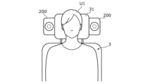
- FIG. 1 is a schematic diagram showing a speaker system of a comparative example.
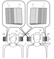
- FIG. 2 is a schematic diagram showing an example of use of a speaker system including an acoustic lens according to an embodiment.
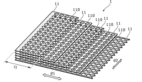
- FIG. 3 is a schematic diagram showing the configuration of the acoustic lens according to the embodiment.
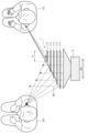
- FIG. 4 is an explanatory diagram of the directivity of the acoustic lens according to the embodiment.
- FIG. 5 is a schematic diagram showing the configuration of an acoustic lens according to a first modification of the embodiment.
- FIG. 6 is a schematic diagram showing the configuration of an acoustic lens according to a second modification of the embodiment.
- FIG. 7 is an explanatory diagram of the directivity of the acoustic lens according to the second modification of the embodiment.
- FIG. 8 is a schematic diagram showing the configuration of an acoustic lens according to a third modification of the embodiment.
- FIG. 1 is a schematic diagram showing a speaker system 200 of a comparative example.
- the speaker system 200 of the comparative example is installed on the headrest 31 of the seat 3.
- the speaker system 200 of the comparative example is installed near the left ear and near the right ear of the user U1 seated on the seat 3, respectively.
- the directivity of the sound waves emitted from the speaker is uniform in the front direction of the speaker. Therefore, in the speaker system 200 of the comparative example, the sound or music played by the speaker is likely to leak to the person sitting in the seat next to seat 3 and the person sitting in the seat located behind seat 3. . In other words, the speaker system 200 of the comparative example has a problem in that sound tends to leak to users other than the target user U1.
- the present disclosure provides an acoustic lens, etc. that easily suppresses sound leaking to users other than the target user U1 by making it easier to control the directivity of sound waves by devising the structure of the acoustic lens.
- the purpose is to
- the acoustic lens according to the first aspect of the present disclosure includes a plurality of first partition plates arranged at intervals in a traveling direction of sound waves emitted from a speaker.
- Each of the plurality of first partition plates has a plurality of holes through which sound waves pass.
- the plurality of first partition plates have different lengths in the first direction.
- the number of the plurality of first partition plates that overlap in the traveling direction of the sound wave decreases from one side to the other in the first direction. It is arranged so that
- the acoustic lens according to the third aspect of the present disclosure overlaps with the plurality of first partition plates in the propagation direction of the sound wave, and has a plurality of first partition plates arranged at intervals. It further includes a second partition plate. Each of the plurality of second partition plates has a plurality of holes through which sound waves pass. The plurality of second partition plates have different lengths in the second direction intersecting the first direction.
- the directivity of the sound waves in the first direction is controlled by the plurality of first partition plates
- the directivity of the sound waves in the second direction is controlled by the plurality of second partition plates.
- the plurality of second partition plates are such that the number of the second partition plates that overlap in the traveling direction of the sound wave decreases as the distance from the center in the second direction increases. It is located in
- the first direction and the second direction are orthogonal to each other in the third or fourth aspect.
- the directivity of the sound waves can be easily controlled in each of the horizontal direction and the vertical direction.
- the diameter of the plurality of holes becomes smaller as the distance from the speaker increases in the direction of propagation of the sound wave.
- the length of the path through which the sound wave passes becomes longer as the number of holes through which the sound wave passes increases, compared to the case where the diameters of each of the multiple holes are the same. It has the advantage that the directivity tends to become sharper.
- the holes do not overlap each other in the direction of propagation of the sound wave.
- a speaker system includes the acoustic lens according to any one of the first to seventh aspects, and a speaker that emits sound waves to the acoustic lens.
- constituent elements that are not described in the independent claims will be described as arbitrary constituent elements. Note that each figure is a schematic diagram and is not necessarily strictly illustrated. Further, in each figure, substantially the same configurations are denoted by the same reference numerals, and overlapping explanations may be omitted or simplified.
- FIG. 2 is a schematic diagram showing an example of use of the speaker system 100 including the acoustic lens 1 according to the embodiment. In FIG. 2, illustration of the speaker 2 is omitted.
- FIG. 3 is a schematic diagram showing the configuration of the acoustic lens 1 according to the embodiment.
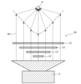
- FIG. 4 is an explanatory diagram of the directivity of the acoustic lens 1 according to the embodiment.
- the speaker system 100 includes an acoustic lens 1 and a speaker 2 (see FIG. 4).
- the speaker system 100 is a system for making a target user U1 listen to sound waves W1 (see FIG. 4) emitted from the speaker 2 and radiated through the acoustic lens 1.
- the speaker system 100 is installed in seats 3 and 3A of a moving body such as a car.
- the seat 3 is the driver's seat of the automobile
- the seat 3A is the passenger seat of the automobile.
- the seats 3 and 3A are lined up in the left-right direction (horizontal direction) of the vehicle on the front side of the vehicle.
- the left-right direction (horizontal direction) of the vehicle will be referred to as a "first direction d1" unless otherwise specified.
- the height direction (vertical direction) of the vehicle will be referred to as a "second direction d2.”
- the speaker system 100 is installed at both ends of the headrest 31 of the seat 3 in the first direction d1. That is, the speaker system 100 is installed near the left ear and near the right ear of the user U1 seated on the seat 3, respectively. Further, the speaker system 100 is installed at both ends of the headrest 31A of the seat 3A in the first direction d1. That is, the speaker system 100 is installed near the left ear and near the right ear of the user U2 seated on the seat 3A.
- the speaker 2 is a device that outputs a sound wave W1 by converting an electrical signal such as an audio signal into vibration of a diaphragm.
- the size, shape, or structure of the diaphragm, magnetic circuit, frame, etc. that constitute the speaker 2 is not particularly limited.
- the speaker 2 is an electrodynamic speaker equipped with a cone-shaped diaphragm.
- the speaker 2 emits a sound wave W1 to the acoustic lens 1. Thereby, the sound wave W1 emitted from the speaker 2 passes through the acoustic lens 1 and is radiated to the outside (atmosphere).
- the acoustic lens 1 includes a plurality (here, five) of first partition plates 11.
- Each first partition plate 11 has a flat plate shape, and is a member that itself does not easily vibrate.
- the material constituting each first partition plate 11 is, for example, wood, resin, metal, ceramics, or the like, and is not particularly limited.
- each first partition plate 11 is arranged at intervals in the traveling direction of the sound wave W1 emitted from the speaker 2.
- each first partition plate 11 may be supported, for example, by a frame-shaped member provided on the outer periphery of each first partition plate 11, or by supporting the adjacent first partition plates 11. It may be supported by a spacer provided therebetween.
- the traveling direction of the sound wave W1 is the traveling direction of the sound wave W1 emitted from the speaker 2, and is not the traveling direction of the sound wave W1 passing through the acoustic lens 1.
- the traveling direction of the sound wave W1 corresponds to a direction perpendicular to both the first direction d1 and the second direction d2.
- the first direction d1 is the horizontal direction
- the second direction d2 is the vertical direction. Therefore, in the embodiment, the first direction d1 and the second direction d2 are orthogonal to each other. Note that the first direction d1 and the second direction d2 only need to intersect with each other, and do not need to be orthogonal to each other.
- each of the plurality of first partition plates 11 has a plurality of holes 110 through which the sound waves W1 pass.
- the hole 110 has a circular shape in a plan view (that is, viewed from the direction of propagation of the sound wave W1), and penetrates the first partition plate 11 in the thickness direction (that is, the direction of propagation of the sound wave W1). are doing.
- the plurality of holes 110 are arranged in a matrix in which m (m is a natural number) holes are arranged in the first direction d1 and n (where n is a natural number) in the second direction d2. It is set up so that
- the plurality of first partition plates 11 have different lengths l1 in the first direction d1.
- the first direction d1 is a direction for controlling the directivity of the sound wave W1.
- the plurality of first partition plates 11 are arranged such that the number of the first partition plates 11 that overlap in the traveling direction of the sound wave W1 decreases from one side (the left side in FIG. 3) to the other side (the right side in FIG. 3) in the first direction d1. There is.
- the plurality of first partition plates 11 are arranged such that the side on which the sound wave W1 is desired to have more directivity in the first direction d1 has a smaller number of overlapping plates in the traveling direction of the sound wave W1.
- the plurality of first partition plates 11 are arranged such that the length l1 in the first direction d1 increases from the top to the bottom in the traveling direction of the sound wave W1. That is, among the plurality of first partition plates 11, the first partition plate 11 located at the uppermost position in the traveling direction of the sound wave W1 has the shortest length l1 in the first direction, and the first partition plate located at the lowermost position has the shortest length l1.
- the length l1 in the first direction d1 of No. 11 is the longest.
- FIG. 4 illustration of each hole 110 is omitted. Further, in FIG. 4, the sound waves W1 passing through each first partition plate 11 actually pass through each hole 110. As shown in FIG. 4, the sound wave W1 passes through each hole 110 of each first partition plate 11 and is radiated to the outside (atmosphere).
- the directivity in the first direction d1 is controlled by changing the length of the path through which the sound wave W1 passes.
- the sound wave W1 emitted from the speaker 2 and reaching the ear of the user U1 seated on the seat 3 is transmitted in the first direction d1 where the user U1 has more overlap with the first partition plate 11, as shown by the broken line. Since the first partition plate 11 is located on one side of the first partition plate 11, the overlapping of the first partition plates 11 hardly affects the path of the sound wave W1. Therefore, since there is almost no difference between the length of the path of the sound wave W1 on one side in the first direction d1 and the length of the path of the sound wave W1 on the other side in the first direction d1, the sound wave W1 reaching the ear of the user U1 The difference in arrival time is small, and the influence of cancellation of the sound wave W1 is small.
- the acoustic lens 1 and speaker system 100 will be described below.
- the plurality of first partition plates 11 arranged at intervals in the traveling direction of the sound wave W1 are made to have different lengths in the first direction d1. Therefore, in the acoustic lens 1 according to the embodiment, the length of the path through which the sound wave W1 passes can be adjusted depending on the number of holes 110 through which the sound wave W1 passes. , the directivity of the sound wave W1 in the first direction d1) can be easily controlled.
- the acoustic lens 1 can control the horizontal directivity of the sound wave W1, with the first direction d1 being the horizontal direction. Therefore, the acoustic lens 1 according to the embodiment and the speaker system 100 using the acoustic lens 1 can solve the problems that the speaker system 200 of the comparative example had.
- the speaker system 100 is arranged near the left ear and the right ear of the user U1 seated on the seat 3, and the sound wave W1 is arranged in the horizontal direction (first direction d1).
- the acoustic lens 1 is arranged so that the directivity is biased toward the user U1.
- the sound wave W1 emitted by the speaker 2 is radiated through the acoustic lens 1 so as to have a directionality deflected toward the user U1 in the horizontal direction, so that the sound wave W1 is directed toward the user U2 who is seated on the seat 3A next to the seat 3. Sound doesn't easily leak out.
- the speaker system 100 is placed near the left ear and near the right ear of the user U2 who is seated on the seat 3A next to the seat 3, and the sound wave W1 is directed toward the user U2 in the horizontal direction (first direction d1).
- the acoustic lens 1 is arranged so that the directivity is deflected toward U2.
- the sound wave W1 emitted by the speaker 2 is radiated through the acoustic lens 1 so as to have a directionality deflected toward the user U2 in the horizontal direction, so that the sound is less likely to leak to the user U1 seated on the seat 3.
- the acoustic lens 1 according to the embodiment and the speaker system 100 using the acoustic lens 1 have the advantage that it is easy to suppress sound leaking to users other than the target user U1 (or user U2).
- FIG. 5 is a schematic diagram showing the configuration of an acoustic lens 1A according to a first modification of the embodiment.
- the diameter R1 of the plurality of holes 110 becomes smaller as the distance from the speaker 2 increases in the traveling direction of the sound wave W1 (in other words, the thickness direction of the first partition plate 11). This is different from the acoustic lens 1 according to the embodiment.
- the diameter R1 of each hole 110 of the first partition plate 11 located at the lowest position is the largest, and the diameter R1 of each hole 110 of the first partition plate 11 located at the highest position is the largest.
- R1 is the smallest.
- the ratio of the total area of the plurality of holes 110 to the area of the first partition plate 11 is defined as the aperture ratio.
- the aperture ratio of each of the plurality of first partition plates 11 becomes smaller as the distance from the speaker 2 increases in the traveling direction of the sound wave W1. Therefore, in the acoustic lens 1A according to the first modification, the length of the path through which the sound wave W1 increases as the number of holes 110 through which it passes increases. Therefore, in the acoustic lens 1A according to the first modification, compared to the acoustic lens 1 according to the embodiment, the sound wave W1 has a directivity that is deflected to one side (the left side in FIG. 5) in the first direction d1. This has the advantage that the directivity of the sound wave W1 tends to become sharper.
- FIG. 6 is a schematic diagram showing the configuration of an acoustic lens 1B according to a second modification of the embodiment.
- the acoustic lens 1B according to the second modification differs from the acoustic lens 1 according to the embodiment in that it further includes a plurality of second partition plates 12.
- Each of the second partition plates 12 has a flat plate shape, and is a member that itself is difficult to vibrate.
- the material constituting each second partition plate 12 is, for example, wood, resin, metal, ceramics, or the like, and is not particularly limited.
- the plurality of second partition plates 12 overlap with the plurality of first partition plates 11 in the traveling direction of the sound wave W1, and are arranged so as to be spaced apart from each other.
- the plurality of second partition plates 12 are arranged such that the first partition plates 11 and the second partition plates 12 are alternately lined up at intervals in the traveling direction of the sound wave W1.
- each second partition plate 12 may be supported by a frame-shaped member or a spacer (not shown).
- each of the plurality of second partition plates 12 has a plurality of holes 120 through which the sound waves W1 pass.
- the plurality of holes 120 of the second partition plate 12 located at the uppermost position in the traveling direction of the sound wave W1 are illustrated, and the other holes 120 are illustrated. Illustration of the plurality of holes 120 of the second partition plate 12 is omitted. Further, in FIG. 6, illustration of the plurality of holes 110 of each first partition plate 11 is omitted.
- the hole 120 has a circular shape in a plan view (that is, when viewed from the traveling direction of the sound wave W1), and extends through the second partition plate 12 in the thickness direction (that is, in the traveling direction of the sound wave W1). Penetrating.
- the plurality of holes 120 are arranged in a matrix in which p (p is a natural number) holes are arranged in the first direction d1 and q (q is a natural number) holes are arranged in the second direction d2. It is set up so that
- the plurality of second partition plates 12 have different lengths l1 in the first direction d1. Further, the plurality of second partition plates 12 have different lengths l2 in the second direction d2 intersecting the first direction d1.
- the second direction d2 is a direction for controlling the directivity of the sound wave W1, similar to the first direction d1.
- the plurality of second partition plates 12 are arranged such that the number of the second partition plates 12 that overlap in the traveling direction of the sound wave W1 decreases as the distance from the center in the second direction d2 decreases.
- the plurality of second partition plates 12 are arranged such that the side on which the sound wave W1 is desired to have directivity in the second direction d2 has a larger number of overlapping plates in the traveling direction of the sound wave W1.
- the plurality of second partition plates 12 are arranged such that the length l2 in the second direction d2 becomes shorter from the top to the bottom in the traveling direction of the sound wave W1. That is, among the plurality of second partition plates 12, the second partition plate 12 located at the uppermost position in the traveling direction of the sound wave W1 has the longest length l2 in the second direction, and the second partition plate located at the lowermost position has the longest length l2.
- the length l2 in the second direction d2 of No. 12 is the shortest.
- FIG. 7 is an explanatory diagram of the directivity of the acoustic lens 1B according to the second modification of the embodiment.
- illustration of each first partition plate 11 and illustration of each hole 120 of each second partition plate 12 are omitted.
- the sound waves W1 passing through each second partition plate 12 actually pass through each hole 110 of each first partition plate 11 and each hole 120 of each second partition plate 12.
- the directivity in the second direction d2 is controlled by changing the length of the path through which the sound wave W1 passes.
- the path that the sound wave W1 emitted from the speaker 2 passes becomes longer in the middle in the second direction d2 where the second partition plates 12 overlap more, and in the second direction where the second partition plates 12 overlap less.
- the end portions at d2 (right end and left end in FIG. 7) become shorter. Therefore, the wavefront of the sound wave W1 can be virtually regarded as a concave wavefront as shown by the dashed line in FIG.
- the acoustic lens 1B has the effect of concentrating the sound wave W1 on the virtual point p, just as a parabolic antenna concentrates radio waves on the focal point. Therefore, the sound pressure level at the virtual point p on the central axis of the acoustic lens 1B increases, and the sound pressure level is suppressed at positions off the central axis, so that the directivity is deflected toward the center in the second direction d2. becomes.
- the plurality of second partition plates 12 arranged at intervals in the traveling direction of the sound wave W1 are made to have different lengths in the second direction d2. , there is an advantage that the directivity of the sound wave W1 (here, the directivity of the sound wave W1 in the second direction d2) can be easily controlled.
- the acoustic lens 1B can control the directivity of the sound wave W1 in the vertical direction, with the second direction d2 being the vertical direction. Therefore, the acoustic lens 1B according to the second modification and the speaker system 100 using the acoustic lens 1B can solve the problem that the speaker system 200 of the comparative example had.
- the speaker system 100 using the acoustic lens 1B is placed near the left ear and near the right ear of the user U1 seated on the seat 3, respectively.
- the sound wave W1 emitted by the speaker 2 is not diffused in the vertical direction through the acoustic lens 1B, but is radiated with a directivity deflected toward the front of the user U1, so that the sound wave W1 is directed toward the rear of the seat 3. It is difficult for sound to go around, and the sound is difficult to leak to a user sitting on a seat located behind the seat 3.
- the aperture ratio of each first partition plate 11 may be decreased as the distance from the speaker 2 increases in the traveling direction of the sound wave W1, similarly to the first modification.
- the aperture ratio of each second partition plate 12 may be decreased as the distance from the speaker 2 increases in the traveling direction of the sound wave W1.
- the aperture ratio of the second partition plate 12 is defined as the ratio of the total area of the plurality of holes 120 to the area of the second partition plate 12 in any second partition plate 12. This configuration has an advantage in that the directivity of the sound wave W1 tends to become sharper than when the aperture ratio of each first partition plate 11 and each second partition plate 12 is not changed.
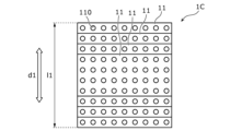
- FIG. 8 is a schematic diagram showing the configuration of an acoustic lens 1C according to a third modification of the embodiment.
- the acoustic lens 1C according to the third modification is arranged so that the first direction d1 is the vertical direction, and the number of overlapping waves in the traveling direction of the sound waves W1 decreases as the distance from the center in the first direction d1 increases.
- the acoustic lens 1 according to the embodiment is configured to mainly control the directivity of the sound wave W1 in the vertical direction, and is configured to mainly control the directivity of the sound wave W1 in the horizontal direction. This is different from the acoustic lens 1 according to the embodiment shown in FIG.
- the plurality of first partition plates 11 have different lengths l1 in the first direction d1.
- the plurality of first partition plates 11 are arranged such that the number of the first partition plates 11 that overlap in the traveling direction of the sound wave W1 decreases as the distance from the center in the first direction d1 increases.
- the plurality of first partition plates 11 are arranged such that the side on which the sound wave W1 is desired to have directivity in the first direction d1 has a larger number of overlapping plates in the traveling direction of the sound wave W1.
- the plurality of first partition plates 11 are arranged such that the length l1 in the first direction d1 increases from the top to the bottom in the traveling direction of the sound wave W1.
- the first partition plate 11 located at the uppermost position in the traveling direction of the sound wave W1 has the shortest length l1 in the first direction
- the first partition plate located at the lowermost position has the shortest length l1.
- the length l1 in the first direction d1 of No. 11 is the longest.
- the acoustic lens 1C can control the directivity of the sound wave W1 in the vertical direction, with the first direction d1 being the vertical direction.
- the aperture ratio of each first partition plate 11 may be decreased as the distance from the speaker 2 increases in the traveling direction of the sound wave W1, similarly to the first modification.
- This configuration has an advantage in that the directivity of the sound waves W1 tends to become sharper than when the aperture ratio of each first partition plate 11 is not changed.
- the holes 110 and 120 that are adjacent to each other in the traveling direction of the sound wave W1 may be arranged so as not to overlap each other when viewed from the traveling direction of the sound wave W1. In other words, at least some of the holes 110 and 120 do not need to overlap each other in the direction of travel of the sound wave W1.
- This configuration has the advantage that since the path through which the sound wave W1 passes can be made longer, the directivity of the sound wave W1 tends to become sharper.
- the shape of the holes 110 and 120 in plan view is not limited to a circular shape, and may be, for example, a rectangular shape or a polygonal shape.
- the present disclosure is useful as a member that controls the directivity of sound waves emitted from a speaker.
Landscapes
- Health & Medical Sciences (AREA)
- Otolaryngology (AREA)
- Physics & Mathematics (AREA)
- Engineering & Computer Science (AREA)
- Acoustics & Sound (AREA)
- Signal Processing (AREA)
- Multimedia (AREA)
- Obtaining Desirable Characteristics In Audible-Bandwidth Transducers (AREA)
Abstract
Description
従来、自動車、航空機、又は列車等の移動体の座席に設置され、座席に着座したユーザに対して音声又は音楽等を再生するスピーカシステムが知られている。図1は、比較例のスピーカシステム200を示す概要図である。比較例のスピーカシステム200は、座席3のヘッドレスト31に設置されている。図1に示す例では、座席3に着座したユーザU1の左耳の近傍、及び右耳の近傍にそれぞれ比較例のスピーカシステム200が設置されている。
[1.構成]
以下、実施の形態に係る音響レンズ1、及び音響レンズ1を備えたスピーカシステム100について説明する。図2は、実施の形態に係る音響レンズ1を備えたスピーカシステム100の使用事例を示す概要図である。図2では、スピーカ2の図示を省略している。図3は、実施の形態に係る音響レンズ1の構成を示す概要図である。図4は、実施の形態に係る音響レンズ1の指向性の説明図である。
以下、実施の形態に係る音響レンズ1及びスピーカシステム100の利点について説明する。上述のように、実施の形態に係る音響レンズ1では、音波W1の進行方向において間隔を空けて並ぶ複数の第1仕切り板11を、それぞれ第1方向d1の長さを互いに異ならせている。このため、実施の形態に係る音響レンズ1では、音波W1が通過する孔110の多寡に応じて音波W1の通過する経路の長さを調整することができるので、音波W1の指向性(ここでは、音波W1の第1方向d1における指向性)を制御しやすい、という利点がある。
以上、実施の形態について説明したが、本開示は、上記の実施の形態に限定されるものではない。
図5は、実施の形態の第1変形例に係る音響レンズ1Aの構成を示す概要図である。第1変形例に係る音響レンズ1Aは、複数の孔110が、音波W1の進行方向(言い換えれば、第1仕切り板11の厚さ方向)において、スピーカ2から離れるにつれて直径R1が小さくなっている点で、実施の形態に係る音響レンズ1と相違する。
図6は、実施の形態の第2変形例に係る音響レンズ1Bの構成を示す概要図である。第2変形例に係る音響レンズ1Bは、複数の第2仕切り板12を更に備えている点で、実施の形態に係る音響レンズ1と相違する。
図8は、実施の形態の第3変形例に係る音響レンズ1Cの構成を示す概要図である。第3変形例に係る音響レンズ1Cは、第1方向d1を鉛直方向としており、かつ、第1方向d1における中央から離れるにつれて音波W1の進行方向において重なる数が少なくなるように配置されている点で、実施の形態に係る音響レンズ1と相違する。つまり、第3変形例に係る音響レンズ1Cは、音波W1の鉛直方向における指向性を主として制御するように構成されている点で、音波W1の水平方向における指向性を主として制御するように構成されている実施の形態に係る音響レンズ1と相違する。
上記実施の形態、及び上記各変形例において、音波W1の進行方向において隣り合う孔110,120は、音波W1の進行方向から見て互いに重なり合わないように配置されていてもよい。言い換えれば、複数の孔110,120は、少なくとも一部が音波W1の進行方向において互いに重なり合っていなくてもよい。この構成では、音波W1が通過する経路を長くすることができるので、音波W1の指向性が鋭くなりやすい、という利点がある。
11 第1仕切り板
110 孔
12 第2仕切り板
120 孔
2 スピーカ
3,3A 座席
31,31A ヘッドレスト
100 スピーカシステム
200 比較例のスピーカシステム
d1 第1方向
d2 第2方向
l1,l2 長さ
p 仮想点
R1 直径
U1,U2 ユーザ
W1 音波
Claims (8)
- スピーカから発せられる音波の進行方向において間隔を空けて並ぶ複数の第1仕切り板を備え、
前記複数の第1仕切り板の各々は、前記音波が通過する複数の孔を有しており、
前記複数の第1仕切り板は、それぞれ第1方向の長さが互いに異なっている、
音響レンズ。 - 前記複数の第1仕切り板は、前記第1方向の一方から他方に向かうにつれて前記音波の進行方向において重なる数が少なくなるように配置されている、
請求項1に記載の音響レンズ。 - 前記音波の進行方向において前記複数の第1仕切り板と重なっており、かつ、間隔を空けて並ぶ複数の第2仕切り板を更に備え、
前記複数の第2仕切り板の各々は、前記音波が通過する複数の孔を有しており、
前記複数の第2仕切り板は、それぞれ前記第1方向と交差する第2方向の長さが互いに異なっている、
請求項1又は2に記載の音響レンズ。 - 前記複数の第2仕切り板は、前記第2方向の中央から離れるにつれて前記音波の進行方向において重なる数が少なくなるように配置されている、
請求項3に記載の音響レンズ。 - 前記第1方向及び前記第2方向は、互いに直交している、
請求項3に記載の音響レンズ。 - 前記複数の孔は、前記音波の進行方向において、前記スピーカから離れるにつれて直径が小さくなっている、
請求項1又は2に記載の音響レンズ。 - 前記複数の孔は、少なくとも一部が前記音波の進行方向において互いに重なり合っていない、
請求項1又は2に記載の音響レンズ。 - 請求項1又は2に記載の音響レンズと、
前記音響レンズに対して前記音波を発する前記スピーカと、を備える、
スピーカシステム。
Priority Applications (4)
| Application Number | Priority Date | Filing Date | Title |
|---|---|---|---|
| CN202380036858.0A CN119174194A (zh) | 2022-05-11 | 2023-05-08 | 声学透镜及扬声器系统 |
| EP23803531.5A EP4525480A4 (en) | 2022-05-11 | 2023-05-08 | ACOUSTIC LENS AND SPEAKER SYSTEM |
| JP2024520440A JPWO2023219054A1 (ja) | 2022-05-11 | 2023-05-08 | |
| US18/930,071 US20250056155A1 (en) | 2022-05-11 | 2024-10-29 | Acoustic lens and loudspeaker system |
Applications Claiming Priority (4)
| Application Number | Priority Date | Filing Date | Title |
|---|---|---|---|
| US202263340653P | 2022-05-11 | 2022-05-11 | |
| US63/340,653 | 2022-05-11 | ||
| JP2023-073692 | 2023-04-27 | ||
| JP2023073692 | 2023-04-27 |
Related Child Applications (1)
| Application Number | Title | Priority Date | Filing Date |
|---|---|---|---|
| US18/930,071 Continuation US20250056155A1 (en) | 2022-05-11 | 2024-10-29 | Acoustic lens and loudspeaker system |
Publications (1)
| Publication Number | Publication Date |
|---|---|
| WO2023219054A1 true WO2023219054A1 (ja) | 2023-11-16 |
Family
ID=88730477
Family Applications (1)
| Application Number | Title | Priority Date | Filing Date |
|---|---|---|---|
| PCT/JP2023/017255 Ceased WO2023219054A1 (ja) | 2022-05-11 | 2023-05-08 | 音響レンズ、及びスピーカシステム |
Country Status (5)
| Country | Link |
|---|---|
| US (1) | US20250056155A1 (ja) |
| EP (1) | EP4525480A4 (ja) |
| JP (1) | JPWO2023219054A1 (ja) |
| CN (1) | CN119174194A (ja) |
| WO (1) | WO2023219054A1 (ja) |
Citations (3)
| Publication number | Priority date | Publication date | Assignee | Title |
|---|---|---|---|---|
| JPS4984017U (ja) * | 1972-11-07 | 1974-07-20 | ||
| JPS49115310A (ja) * | 1973-03-06 | 1974-11-05 | ||
| JPS55155179U (ja) | 1979-04-24 | 1980-11-08 |
Family Cites Families (3)
| Publication number | Priority date | Publication date | Assignee | Title |
|---|---|---|---|---|
| US2580439A (en) * | 1949-09-07 | 1952-01-01 | Bell Telephone Labor Inc | Directional acoustic system |
| US2805728A (en) * | 1953-08-27 | 1957-09-10 | Gen Dynamics Corp | Sound dispersion device with internal divergent acoustical lens |
| JPS51103930U (ja) * | 1975-02-18 | 1976-08-20 |
-
2023
- 2023-05-08 EP EP23803531.5A patent/EP4525480A4/en active Pending
- 2023-05-08 JP JP2024520440A patent/JPWO2023219054A1/ja active Pending
- 2023-05-08 CN CN202380036858.0A patent/CN119174194A/zh active Pending
- 2023-05-08 WO PCT/JP2023/017255 patent/WO2023219054A1/ja not_active Ceased
-
2024
- 2024-10-29 US US18/930,071 patent/US20250056155A1/en active Pending
Patent Citations (3)
| Publication number | Priority date | Publication date | Assignee | Title |
|---|---|---|---|---|
| JPS4984017U (ja) * | 1972-11-07 | 1974-07-20 | ||
| JPS49115310A (ja) * | 1973-03-06 | 1974-11-05 | ||
| JPS55155179U (ja) | 1979-04-24 | 1980-11-08 |
Non-Patent Citations (1)
| Title |
|---|
| See also references of EP4525480A4 |
Also Published As
| Publication number | Publication date |
|---|---|
| EP4525480A4 (en) | 2025-08-06 |
| CN119174194A (zh) | 2024-12-20 |
| US20250056155A1 (en) | 2025-02-13 |
| EP4525480A1 (en) | 2025-03-19 |
| JPWO2023219054A1 (ja) | 2023-11-16 |
Similar Documents
| Publication | Publication Date | Title |
|---|---|---|
| CN112313967B (zh) | 扬声器单元 | |
| US8750540B2 (en) | Omnidirectional speaker | |
| JP6286583B2 (ja) | ラウドスピーカシステム | |
| CA2515281C (en) | Vehicle loudspeaker array | |
| EP3734991B1 (en) | Loudspeaker, loudspeaker system, stereo loudspeaker system, and on-board stereo loudspeaker system | |
| CN101904180A (zh) | 具有指向性调整板的扬声器装置 | |
| JP2011091645A (ja) | スピーカ振動板及びスピーカ装置 | |
| KR20130069462A (ko) | 스피커 시스템 | |
| US8249268B2 (en) | Woofer-less and enclosure-less loudspeaker system | |
| JP7310970B2 (ja) | スピーカ | |
| JPH10224877A (ja) | 車載用スピーカシステム | |
| WO2023219054A1 (ja) | 音響レンズ、及びスピーカシステム | |
| US7577265B2 (en) | Loudspeaker system providing improved sound presence and frequency response in mid and high frequency ranges | |
| JP5720158B2 (ja) | バイノーラル録音された音信号の再生方法および再生装置 | |
| KR101634279B1 (ko) | 스피커용 입체 음향 가이드, 및 이를 구비한 스피커 | |
| KR102097891B1 (ko) | 스피커용 입체 음향 가이드 및 이를 구비한 스피커 | |
| JP2606441B2 (ja) | 車載用スピーカ装置 | |
| US20250063297A1 (en) | Acoustic lens and loudspeaker system | |
| JP2003501984A (ja) | スピーカー | |
| WO2023081437A1 (en) | Instrument panel speaker system | |
| JP6286158B2 (ja) | デュアル電磁アセンブリを有するラウドスピーカシステム | |
| JP2008252405A (ja) | スピーカー用ディフューザーおよびこれを用いたスピーカーシステム | |
| HK1171892A (zh) | 全向扬声器 |
Legal Events
| Date | Code | Title | Description |
|---|---|---|---|
| 121 | Ep: the epo has been informed by wipo that ep was designated in this application |
Ref document number: 23803531 Country of ref document: EP Kind code of ref document: A1 |
|
| WWE | Wipo information: entry into national phase |
Ref document number: 2024520440 Country of ref document: JP |
|
| WWE | Wipo information: entry into national phase |
Ref document number: 2023803531 Country of ref document: EP |
|
| NENP | Non-entry into the national phase |
Ref country code: DE |
|
| ENP | Entry into the national phase |
Ref document number: 2023803531 Country of ref document: EP Effective date: 20241211 |