WO2023219110A1 - 固定具 - Google Patents
固定具 Download PDFInfo
- Publication number
- WO2023219110A1 WO2023219110A1 PCT/JP2023/017603 JP2023017603W WO2023219110A1 WO 2023219110 A1 WO2023219110 A1 WO 2023219110A1 JP 2023017603 W JP2023017603 W JP 2023017603W WO 2023219110 A1 WO2023219110 A1 WO 2023219110A1
- Authority
- WO
- WIPO (PCT)
- Prior art keywords
- fixed
- column
- fixing
- screw
- connecting portion
- Prior art date
- Legal status (The legal status is an assumption and is not a legal conclusion. Google has not performed a legal analysis and makes no representation as to the accuracy of the status listed.)
- Ceased
Links
Images




Classifications
-
- F—MECHANICAL ENGINEERING; LIGHTING; HEATING; WEAPONS; BLASTING
- F16—ENGINEERING ELEMENTS AND UNITS; GENERAL MEASURES FOR PRODUCING AND MAINTAINING EFFECTIVE FUNCTIONING OF MACHINES OR INSTALLATIONS; THERMAL INSULATION IN GENERAL
- F16B—DEVICES FOR FASTENING OR SECURING CONSTRUCTIONAL ELEMENTS OR MACHINE PARTS TOGETHER, e.g. NAILS, BOLTS, CIRCLIPS, CLAMPS, CLIPS OR WEDGES; JOINTS OR JOINTING
- F16B5/00—Joining sheets or plates, e.g. panels, to one another or to strips or bars parallel to them
- F16B5/02—Joining sheets or plates, e.g. panels, to one another or to strips or bars parallel to them by means of fastening members using screw-thread
- F16B5/0216—Joining sheets or plates, e.g. panels, to one another or to strips or bars parallel to them by means of fastening members using screw-thread the position of the plates to be connected being adjustable
- F16B5/0233—Joining sheets or plates, e.g. panels, to one another or to strips or bars parallel to them by means of fastening members using screw-thread the position of the plates to be connected being adjustable allowing for adjustment perpendicular to the plane of the plates
-
- F—MECHANICAL ENGINEERING; LIGHTING; HEATING; WEAPONS; BLASTING
- F16—ENGINEERING ELEMENTS AND UNITS; GENERAL MEASURES FOR PRODUCING AND MAINTAINING EFFECTIVE FUNCTIONING OF MACHINES OR INSTALLATIONS; THERMAL INSULATION IN GENERAL
- F16B—DEVICES FOR FASTENING OR SECURING CONSTRUCTIONAL ELEMENTS OR MACHINE PARTS TOGETHER, e.g. NAILS, BOLTS, CIRCLIPS, CLAMPS, CLIPS OR WEDGES; JOINTS OR JOINTING
- F16B23/00—Specially shaped nuts or heads of bolts or screws for rotations by a tool
- F16B23/0084—Specially shaped nuts or heads of bolts or screws for rotations by a tool with a threaded engagement between the head of the bolt or screw and the tool
-
- F—MECHANICAL ENGINEERING; LIGHTING; HEATING; WEAPONS; BLASTING
- F16—ENGINEERING ELEMENTS AND UNITS; GENERAL MEASURES FOR PRODUCING AND MAINTAINING EFFECTIVE FUNCTIONING OF MACHINES OR INSTALLATIONS; THERMAL INSULATION IN GENERAL
- F16B—DEVICES FOR FASTENING OR SECURING CONSTRUCTIONAL ELEMENTS OR MACHINE PARTS TOGETHER, e.g. NAILS, BOLTS, CIRCLIPS, CLAMPS, CLIPS OR WEDGES; JOINTS OR JOINTING
- F16B35/00—Screw-bolts; Stay-bolts; Screw-threaded studs; Screws; Set screws
- F16B35/04—Screw-bolts; Stay-bolts; Screw-threaded studs; Screws; Set screws with specially-shaped head or shaft in order to fix the bolt on or in an object
-
- F—MECHANICAL ENGINEERING; LIGHTING; HEATING; WEAPONS; BLASTING
- F16—ENGINEERING ELEMENTS AND UNITS; GENERAL MEASURES FOR PRODUCING AND MAINTAINING EFFECTIVE FUNCTIONING OF MACHINES OR INSTALLATIONS; THERMAL INSULATION IN GENERAL
- F16B—DEVICES FOR FASTENING OR SECURING CONSTRUCTIONAL ELEMENTS OR MACHINE PARTS TOGETHER, e.g. NAILS, BOLTS, CIRCLIPS, CLAMPS, CLIPS OR WEDGES; JOINTS OR JOINTING
- F16B37/00—Nuts or like thread-engaging members
- F16B37/04—Devices for fastening nuts to surfaces, e.g. sheets, plates
-
- F—MECHANICAL ENGINEERING; LIGHTING; HEATING; WEAPONS; BLASTING
- F16—ENGINEERING ELEMENTS AND UNITS; GENERAL MEASURES FOR PRODUCING AND MAINTAINING EFFECTIVE FUNCTIONING OF MACHINES OR INSTALLATIONS; THERMAL INSULATION IN GENERAL
- F16B—DEVICES FOR FASTENING OR SECURING CONSTRUCTIONAL ELEMENTS OR MACHINE PARTS TOGETHER, e.g. NAILS, BOLTS, CIRCLIPS, CLAMPS, CLIPS OR WEDGES; JOINTS OR JOINTING
- F16B5/00—Joining sheets or plates, e.g. panels, to one another or to strips or bars parallel to them
- F16B5/02—Joining sheets or plates, e.g. panels, to one another or to strips or bars parallel to them by means of fastening members using screw-thread
- F16B5/0241—Joining sheets or plates, e.g. panels, to one another or to strips or bars parallel to them by means of fastening members using screw-thread with the possibility for the connection to absorb deformation, e.g. thermal or vibrational
-
- F—MECHANICAL ENGINEERING; LIGHTING; HEATING; WEAPONS; BLASTING
- F16—ENGINEERING ELEMENTS AND UNITS; GENERAL MEASURES FOR PRODUCING AND MAINTAINING EFFECTIVE FUNCTIONING OF MACHINES OR INSTALLATIONS; THERMAL INSULATION IN GENERAL
- F16B—DEVICES FOR FASTENING OR SECURING CONSTRUCTIONAL ELEMENTS OR MACHINE PARTS TOGETHER, e.g. NAILS, BOLTS, CIRCLIPS, CLAMPS, CLIPS OR WEDGES; JOINTS OR JOINTING
- F16B5/00—Joining sheets or plates, e.g. panels, to one another or to strips or bars parallel to them
- F16B5/02—Joining sheets or plates, e.g. panels, to one another or to strips or bars parallel to them by means of fastening members using screw-thread
- F16B5/0275—Joining sheets or plates, e.g. panels, to one another or to strips or bars parallel to them by means of fastening members using screw-thread the screw-threaded element having at least two axially separated threaded portions
Definitions
- the present invention relates to a fixture for positioning and fixing an object to be fixed and an object to be fixed in a predetermined positional relationship.
- the axis of a through hole that passes through the plate-shaped object that extends along a plane that intersects the axis of the column in the front and back directions of the object to be fixed is known.
- a fixture is known for positioning and fixing the column in a positional relationship along the axis of the column.
- the fixture described in Patent Document 1 has a columnar body ( A first fixing member (through bolt) connected to the fixing bolt (fixing bolt), and a second fixing member (nut) connected to the first fixing member through a through hole (bolt hole) on the other surface side of the object to be fixed. and a screw-shaped third fixing member (tightening bolt) that sandwiches and fixes the first fixing member between the object and the column from the other side of the fixing target.
- the first fixing member is fixed to the column by the third fixing member, and after positioning the fixing object with the flange (adjustment member support surface) of the first fixing member, the fixing object is fixed to the first fixing member. It is fixed by being sandwiched between the flange of the member and the second fixing member.
- the first fixing member is fixed at an arbitrary position in the axial direction of the column, and then held in that state so as not to rotate, and then the third fixing member is fitted to the column.
- the position at which the object to be fixed that is, the position of the flange
- the position at which the object to be fixed that is, the position of the flange
- all operations from positioning and fixing the object to be fixed can be performed from both the front and back sides of the object to be fixed.
- the present invention was made to solve these problems, and its purpose is to provide a technique for improving the workability of a fixing tool compared to conventional ones.
- a first aspect of the present disclosure for solving the above problem is to fix a plate-shaped object to be fixed that extends along a plane intersecting the axis of the column to an object to be fixed that includes a screw-like column.
- the extension part has a male thread for connection formed along the outer peripheral surface of the area that can reach the side, and the member expands from the connection part to a larger diameter than the through hole, and the connection part is fitted with the column.
- a flange portion formed with a contact surface that can directly or indirectly contact one of the front and back surfaces of the object to be fixed in the fixed state, and the screw of the connecting portion and the male screw of the extending portion are , are each formed with the same thread pitch as the column.
- the second aspect further includes a fixing member that can be connected to the extending portion on the other surface side in the front and back directions of the fixing target, and the fixing member is connected to the extending portion in the front and back directions of the fixing target.
- It is a cylindrical member that extends to surround a part of the area located on the other side around the axis of the column, and can be fitted with the male screw of the extension part along the inner peripheral surface of the fixed member.
- Female threads for connection are formed with the same thread pitch as the column body.
- the connecting portion is a cylindrical member that extends to surround the column around the axis of the column, and the connecting portion
- the screw is a female connection screw that is formed along the inner peripheral surface of the connection part and can fit into the male screw of the column.
- the object to be fixed is positioned relative to the object by the flange portion or the fixing member, and the object to be fixed is connected between the flange portion and the fixing member. Secure it by pinching it. In this way, the work of positioning and fixing the object to be fixed relative to the object to be fixed can all be performed from the other side of the object to be fixed in the front and back directions.
- the above-mentioned fixing device can be displaced to any position in the axial direction of the column depending on the state of engagement with the screw of the column, so the flange portion can cover the object to be fixed depending on the position of the fixing device.
- the position relative to the fixed object can also be adjusted arbitrarily.
- the fixing member can be moved to any position in the axial direction of the column depending on the fitting state with the male screw of the extension, so the fixing member can be fixed depending on the position of the fixing member.
- the position of the object relative to the object to be fixed can also be adjusted arbitrarily.
- the end part side is held and the axis of the column of the extending part is aligned.
- a holding piece is formed to control the rotation around it.
- the holding piece by using the holding piece, the work of holding the fixture body and rotating the fixing member can be effectively carried out.
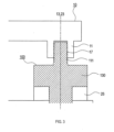
- FIG. 2 is a front cross-sectional view taken along a plane formed by an axial direction and an intersecting direction thereof, showing a state in which a fixture according to an embodiment of the present invention is attached.
- FIG. 1 is a front sectional view of a fixture according to an embodiment of the present invention, taken in cross section along a plane formed by an axial direction and a direction intersecting the axial direction.
- FIG. 7 is a front cross-sectional view of a fixture according to another embodiment of the invention.
- FIG. 6 is a front cross-sectional view of a fixture according to yet another embodiment of the invention.
- FIG. 2 is a front sectional view showing how a fixing target is positioned and fixed to a fixing target using a fixture according to an embodiment of the present invention.
- Fixing tool 10... Object to be fixed, 11... Column, 13... Axis line, 15... Male thread, 17... Female thread, 20... Fixed object, 21... Through hole, 23... Axis line, 25... Buffer member , 27... Buffer member, 100... Main body, 111... Screw, 121... Male thread, 123... Holding piece, 130... Flange portion, 131... Contact surface, 200... Fixing member, 210... Female thread, 220... Contact surface.
- the fixing tool 1 has a plate-like structure extending along a plane intersecting the axis 13 of the column 11 with respect to an object to be fixed 10 having a screw-shaped column 11. This is for positioning and fixing the object to be fixed 20 in such a positional relationship that the axis 23 of the through hole 21 passing through the object to be fixed 20 in the front and back directions is along the axis 13 of the column 11.
- a case is illustrated in which the axis 23 of the through hole 21 coincides with the axis 13 of the column 11, but in the present disclosure, both axes do not coincide depending on factors such as fixing of each part and accuracy of positioning. It may also include cases.
- the column 11 extends downward in FIG. 1 from the back surface of the object to be fixed 10, and the outer circumferential surface of the column 11 is )
- a configuration in which a male thread 15 spirally extending toward the side is formed is illustrated.
- the fixing tool 1 has a main body 100 connected to a column 11 on one surface (the top surface in FIG. 1) of the object 20 in the front and back directions, and a main body 100 connected to the column 11 on the other surface (the bottom surface in FIG. ) side is configured to be connected to the fixing member 200.
- the main body 100 is interposed between the fixed object 10 and the fixed object 20, and includes a connecting portion 110, an extending portion 120, and a flange portion 130, as shown in FIG.
- the connecting portion 110 has a connecting screw 111 that can be fitted to the column 11 on one side of the object 20 in the front and back directions.
- the position of the main body 100 in the directions of the axes 13 and 23 can be arbitrarily displaced depending on how long the male screw 15 of the column 11 is fitted into the screw 111.
- the connecting portion 110 is a cylindrical member that extends to surround the columnar body 11 around the axes 13 and 23, and has a smaller diameter than the through hole 21.
- the difference between the diameter of the connecting portion 110 and the diameter of the through hole 21 is such that even if the axis 23 of the through hole 21 does not match the axis 13 of the column 11, the difference between the diameter of the connecting portion 110 and the diameter of the through hole 21 is such that even if the axis 23 of the through hole 21 does not coincide with the axis 13 of the column 11, It is specified that the extension portion 120 can reach the other side of the surface.
- the connecting portion 110 has an open end (upper end in FIGS. 1 and 2), and a closed end (lower end in FIGS. 1 and 2).
- the screw 111 is a female thread formed along the inner peripheral surface of the connecting portion 110, and is formed so as to extend spirally from the distal end side to the distal end side of the inner peripheral surface of the connecting portion 110. .
- the screws 111 are formed with the same thread pitch as the male screws 15 of the column 11.
- the extending portion 120 is a columnar member that extends from the connecting portion 110 through the through hole 21 to reach the other surface side of the fixed object 20 in the front and back direction, and has a smaller diameter than the through hole 21.
- a male thread 121 for connection is formed in a region of this extending portion 120 that reaches the other surface side in the front and back directions of the object to be fixed 20 and is adjacent to the through hole 21 along the outer peripheral surface of this region. has been done.
- the external thread 121 extends spirally from the distal end (the upper end of FIGS. 1 and 2) to the distal end (the lower end of FIGS. 1 and 2) on the outer circumferential surface of the extending portion 120, and It is formed with the same thread pitch as the male thread 15 of No. 11 and the thread 111 of the connecting portion 110.
- a holding piece 123 for control is formed.
- This holding piece 123 has an outer shape having at least two opposing sides in a cross-sectional view intersecting the axes 13 and 23, and is configured such that a tool such as a wrench can be fitted into the outer shape of the holding piece 123. has been done.
- the shape may be a polygon such as a quadrangle or a hexagon.
- the flange portion 130 is a member that expands from the connecting portion 110 to a larger diameter than the through hole 21, and when the connecting portion 110 is fitted to the column 11, it is directly connected to one surface of the object to be fixed 20 in the front and back directions.
- a contact surface 131 that makes indirect contact is formed.
- a cylindrical buffer member 25 is arranged between the flange portion 130 and the fixed object 20, and the contact surface 131 indirectly contacts the fixed object 20 via this buffer member 25. It is configured as follows. Here, a washer is used as the buffer member 25.
- a part of the extending portion 120 located on the other side of the fixing target 20 in the front and back directions (an area adjacent to the through hole 21) is aligned with the axis 13.
- 23 is a cylindrical member that extends to surround it.
- this fixing member 200 is formed with a female thread 210 for connection that can fit into the male thread 121 of the extending portion 120 along its inner peripheral surface.
- the female thread 210 is formed so that its inner circumferential surface extends spirally from the distal end (upper end in FIGS. 1 and 2) toward the distal end (lower end in FIGS. 1 and 2).
- the female threads 210 are formed with the same thread pitch as the male threads 15 of the columnar body 11, the threads 111 of the connecting portion 110, and the male threads 121 of the extension portion 120.
- the fixing member 200 is a member that expands to a larger diameter than the through hole 21, and in a state where it is fitted with the extension portion 120, it directly or indirectly contacts the other surface of the fixing object 20 in the front and back directions.
- a contact surface 220 is formed.
- a cylindrical buffer member 27 is arranged between the fixing member 200 and the fixing target 20, so that the contact surface 220 indirectly contacts the fixing target 20 via the buffer member 27. It is composed of Here, a washer is used as the buffer member 27.
- the fixture 1 is used to fix the fixed object 20 at an arbitrary position below the fixed object 10.
- the fixture 1 may be capable of fixing the fixing object 20 at any position relative to the fixing object 10, regardless of the positional relationship between the fixing object 10 and the fixing object 20. .
- the columnar body 11 is provided with a male thread
- the connecting portion 110 is provided with a female thread as a screw 111.
- the male and female threads of both are formed in reverse, that is, the female thread 17 is formed in the column 11, and the male thread is formed as the screw 111 in the connecting part 110. It may be configured as follows.
- the holding piece 123 having a polygonal outer shape is formed on the distal end side of the male thread 121.
- the holding piece 123 may also be formed as a recess that is formed from the tip to the end of the extending portion 120 and has a polygonal outer diameter in a cross-sectional view intersecting the axes 13 and 23. good.
- the flange portion 130 of the main body 100 and the fixed object 20 indirectly contact each other via the buffer member 25, and the fixed member 200 and the fixed object 20 indirectly contact each other via the buffer member 27.
- An example of a device that is configured to come in contact with is illustrated.
- one or both of the flange 130 of the main body 100 and the fixed object 20, and the fixed member 200 and the fixed object 20, are configured to be in direct contact without using the buffer members 25 and 27. Good too.
- the connecting portion 110 is configured as a cylindrical member with a closed end.
- a configuration is illustrated in which the region from the distal end side of the connecting portion 110 to the distal end of the extending portion 120 is a columnar member.
- it may be a cylindrical member that extends so as to surround the axes 13 and 23 over the entire length of the region from the distal end side of the connecting portion 110 to the distal end of the extending portion 120.
- the object 20 to be fixed is sandwiched and fixed between the flange portion 130 and the fixing member 200.
- the work of positioning and fixing the object to be fixed 20 relative to the object to be fixed 10 can all be carried out from the other side of the object to be fixed 20 in the front and back directions.
- the position of the flange portion 130 can be changed depending on the position. Accordingly, the position of the fixed object 20 relative to the fixed object 10 can also be adjusted arbitrarily.
- the fixing member 200 when the fixing member 200 is attached, by holding the fixing member 200 so as not to rotate, only the main body 100 can be displaced with respect to the column 11 (part (a) of FIG. 5). reference).
- the fixing member 200 can be displaced to any position in the directions of the axes 13 and 23 depending on the fitting state with the male screw 121 of the extending portion 120, the fixing member 200 Accordingly, the position of the fixed object 20 relative to the fixed object 10 can also be adjusted arbitrarily.
- the fixing member 200 when rotating the fixing member 200, by holding the main body 100 so as not to rotate, only the fixing member 200 can be displaced with respect to the column 11 (part (b) in FIG. )reference).
- each screw is formed with the same thread pitch, and thus positioning and fixing can be accomplished as a series of operations, improving work efficiency.
- the holding piece 123 by using the holding piece 123, the work of holding the main body 100 and rotating the fixing member 200 can be effectively carried out.
Landscapes
- Engineering & Computer Science (AREA)
- General Engineering & Computer Science (AREA)
- Mechanical Engineering (AREA)
- Clamps And Clips (AREA)
- Connection Of Plates (AREA)
- Mutual Connection Of Rods And Tubes (AREA)
Abstract
Description
(1)全体構成
固定具1は、図1に示すように、ネジ状の柱体11を備える被固定対象物10に対し、柱体11の軸線13と交差する面に沿って拡がる板状の固定対象物20を、固定対象物20の表裏方向に貫通する貫通孔21の軸線23が柱体11の軸線13に沿う位置関係で位置決めして固定するためのものである。ここでは、貫通孔21の軸線23が柱体11の軸線13と一致する場合を例示しているが、本開示は、各部の固定や位置決めの精度などの要因に応じて両方の軸線が一致しない場合も含み得る。
(2)変形例
以上、本発明の実施の形態について説明したが、本発明は、上記実施形態に何ら限定されることはなく、本発明の技術的範囲に属する限り種々の形態をとり得る。
(3)作用効果
上記実施形態の固定具1では、連結部110を柱体11と嵌合させた後、フランジ部130または固定部材200で固定対象物20を被固定対象物10に対して位置決めしつつ、この固定対象物20をフランジ部130と固定部材200とにより挟んで固定する。こうして、固定対象物20を被固定対象物10に対して位置決めして固定するまでの作業は、固定対象物20における表裏方向の他方側から全て実施できる。
Claims (4)
- ネジ状の柱体を備える被固定対象物に対し、前記柱体の軸線と交差する面に沿って拡がる板状の固定対象物を、前記固定対象物の表裏方向に貫通する貫通孔の軸線が前記柱体の前記軸線に沿う位置関係で位置決めして固定するための固定具であって、
前記固定対象物における前記表裏方向の一方の面側で、前記柱体と嵌合可能な連結用のネジが形成されている連結部と、
前記連結部から、前記貫通孔を通じて前記固定対象物における前記表裏方向の他方の面側に到達し得る長さで延びており、前記他方の面側に到達し得る領域の外周面に沿って連結用の雄ネジが形成されている延出部と、
前記連結部から前記貫通孔よりも大径に拡がる部材であり、前記連結部を前記柱体と嵌合させた状態で、前記固定対象物における前記表裏方向の前記一方の面と直接または間接的に接触し得る接触面が形成されているフランジ部と、を備え、
前記連結部の前記ネジおよび前記延出部の前記雄ネジは、それぞれ前記柱体と同じネジピッチで形成されている、
固定具。 - 前記固定対象物における前記表裏方向の前記他方の面側で、前記延出部と連結され得る固定部材、をさらに備えており、
前記固定部材は、前記延出部のうち、前記固定対象物における前記表裏方向の前記他方の面側に位置する一部の領域を前記柱体の前記軸線周りに包囲するように延びる筒状の部材であり、前記固定部材の内周面に沿って前記延出部の雄ネジと嵌合可能な連結用の雌ネジが、前記柱体と同じネジピッチで形成されている、
請求項1に記載の固定具。 - 前記柱体の外周面に沿って雄ネジが形成されている場合において、
前記連結部は、前記柱体を前記柱体の前記軸線周りに包囲するように延びる筒状の部材であり、前記連結部の前記ネジは、前記連結部の内周面に沿って形成された、前記柱体の前記雄ネジと嵌合可能な連結用の雌ネジである、
請求項1または2に記載の固定具。 - 前記延出部のうち、前記固定対象物における前記表裏方向の前記他方の面側に到達し得る領域の端部側には、該端部側を保持して前記延出部の前記柱体の前記軸線周りの回転を制御するための保持片が形成されている、
請求項1~3のいずれか一項に記載の固定具。
Priority Applications (3)
| Application Number | Priority Date | Filing Date | Title |
|---|---|---|---|
| EP23803585.1A EP4524409A4 (en) | 2022-05-11 | 2023-05-10 | MOUNTING ACCESSORY |
| CN202380039462.1A CN119183505A (zh) | 2022-05-11 | 2023-05-10 | 固定件 |
| KR1020247036880A KR20240172215A (ko) | 2022-05-11 | 2023-05-10 | 고정구 |
Applications Claiming Priority (2)
| Application Number | Priority Date | Filing Date | Title |
|---|---|---|---|
| JP2022078471A JP7793474B2 (ja) | 2022-05-11 | 2022-05-11 | 固定具 |
| JP2022-078471 | 2022-05-11 |
Publications (1)
| Publication Number | Publication Date |
|---|---|
| WO2023219110A1 true WO2023219110A1 (ja) | 2023-11-16 |
Family
ID=88730338
Family Applications (1)
| Application Number | Title | Priority Date | Filing Date |
|---|---|---|---|
| PCT/JP2023/017603 Ceased WO2023219110A1 (ja) | 2022-05-11 | 2023-05-10 | 固定具 |
Country Status (5)
| Country | Link |
|---|---|
| EP (1) | EP4524409A4 (ja) |
| JP (1) | JP7793474B2 (ja) |
| KR (1) | KR20240172215A (ja) |
| CN (1) | CN119183505A (ja) |
| WO (1) | WO2023219110A1 (ja) |
Citations (3)
| Publication number | Priority date | Publication date | Assignee | Title |
|---|---|---|---|---|
| JPH0347826U (ja) | 1989-09-19 | 1991-05-07 | ||
| JPH0347826Y2 (ja) * | 1985-05-31 | 1991-10-11 | ||
| US20110158766A1 (en) * | 2009-12-29 | 2011-06-30 | Studio Milan Design Build, Inc. | Threaded connector for pole, machinery and structural elements |
Family Cites Families (2)
| Publication number | Priority date | Publication date | Assignee | Title |
|---|---|---|---|---|
| US11408460B2 (en) * | 2017-10-31 | 2022-08-09 | Tesla, Inc. | Tolerance compensator |
| DE102017131235A1 (de) * | 2017-12-22 | 2019-06-27 | Witte Automotive Gmbh | Toleranzausgleichsvorrichtung |
-
2022
- 2022-05-11 JP JP2022078471A patent/JP7793474B2/ja active Active
-
2023
- 2023-05-10 WO PCT/JP2023/017603 patent/WO2023219110A1/ja not_active Ceased
- 2023-05-10 CN CN202380039462.1A patent/CN119183505A/zh active Pending
- 2023-05-10 KR KR1020247036880A patent/KR20240172215A/ko active Pending
- 2023-05-10 EP EP23803585.1A patent/EP4524409A4/en active Pending
Patent Citations (3)
| Publication number | Priority date | Publication date | Assignee | Title |
|---|---|---|---|---|
| JPH0347826Y2 (ja) * | 1985-05-31 | 1991-10-11 | ||
| JPH0347826U (ja) | 1989-09-19 | 1991-05-07 | ||
| US20110158766A1 (en) * | 2009-12-29 | 2011-06-30 | Studio Milan Design Build, Inc. | Threaded connector for pole, machinery and structural elements |
Non-Patent Citations (1)
| Title |
|---|
| See also references of EP4524409A4 |
Also Published As
| Publication number | Publication date |
|---|---|
| EP4524409A1 (en) | 2025-03-19 |
| EP4524409A4 (en) | 2026-04-29 |
| KR20240172215A (ko) | 2024-12-09 |
| JP2023167352A (ja) | 2023-11-24 |
| JP7793474B2 (ja) | 2026-01-05 |
| CN119183505A (zh) | 2024-12-24 |
Similar Documents
| Publication | Publication Date | Title |
|---|---|---|
| ES2244711T3 (es) | Disposicion de compensacion de tolerancias. | |
| US10309437B2 (en) | Screw | |
| WO2008129854A1 (en) | Fastening device | |
| US20090103974A1 (en) | Ball stud system for use within a ball joint | |
| US11319981B2 (en) | Bolt provided with an anti-rotation device | |
| CN101970890A (zh) | 螺纹插件及车辆部件 | |
| SE448491B (sv) | Gengat festorgan | |
| US20150219144A1 (en) | Fastening device | |
| ES2369555T3 (es) | Utilización de una porción de guía en un perno. | |
| US20100260578A1 (en) | Captive securing arrangement | |
| WO2023219110A1 (ja) | 固定具 | |
| ES2751673T3 (es) | Dispositivo para fijar una pieza de montaje a un soporte | |
| CN115803535A (zh) | 偏移连接装置 | |
| JP6657824B2 (ja) | ロボットのハンド接続構造 | |
| JP5937041B2 (ja) | 鋼材接合構造 | |
| JP2007524042A (ja) | 下部構造体に固定される、プレートのための保持体 | |
| WO2017183237A1 (ja) | キーレンチ | |
| KR20200018668A (ko) | 직경 감소 부분을 가지는 스크류를 가진 프로파일 클램프 | |
| JP2019120338A (ja) | ねじの緩み止め構造 | |
| JP2002039142A (ja) | 緩み止め座金 | |
| ES3062540T3 (en) | Screw | |
| JP6462616B2 (ja) | 鋼材接合構造 | |
| JP2007050499A (ja) | ストッパ構造,ストッパ部材固着構造及びストッパ部材取付け構造 | |
| RU2361125C1 (ru) | Болт | |
| JP7496655B1 (ja) | 取付け治具付ラグスクリューボルト |
Legal Events
| Date | Code | Title | Description |
|---|---|---|---|
| 121 | Ep: the epo has been informed by wipo that ep was designated in this application |
Ref document number: 23803585 Country of ref document: EP Kind code of ref document: A1 |
|
| ENP | Entry into the national phase |
Ref document number: 20247036880 Country of ref document: KR Kind code of ref document: A |
|
| WWE | Wipo information: entry into national phase |
Ref document number: 1020247036880 Country of ref document: KR |
|
| WWE | Wipo information: entry into national phase |
Ref document number: 18863364 Country of ref document: US |
|
| WWE | Wipo information: entry into national phase |
Ref document number: 2023803585 Country of ref document: EP |
|
| NENP | Non-entry into the national phase |
Ref country code: DE |
|
| ENP | Entry into the national phase |
Ref document number: 2023803585 Country of ref document: EP Effective date: 20241211 |