WO2023219158A1 - 発泡体、及び積層構造体 - Google Patents
発泡体、及び積層構造体 Download PDFInfo
- Publication number
- WO2023219158A1 WO2023219158A1 PCT/JP2023/017881 JP2023017881W WO2023219158A1 WO 2023219158 A1 WO2023219158 A1 WO 2023219158A1 JP 2023017881 W JP2023017881 W JP 2023017881W WO 2023219158 A1 WO2023219158 A1 WO 2023219158A1
- Authority
- WO
- WIPO (PCT)
- Prior art keywords
- foam
- resin
- layer
- foam according
- modified lignin
- Prior art date
- Legal status (The legal status is an assumption and is not a legal conclusion. Google has not performed a legal analysis and makes no representation as to the accuracy of the status listed.)
- Ceased
Links
Images
Classifications
-
- C—CHEMISTRY; METALLURGY
- C08—ORGANIC MACROMOLECULAR COMPOUNDS; THEIR PREPARATION OR CHEMICAL WORKING-UP; COMPOSITIONS BASED THEREON
- C08L—COMPOSITIONS OF MACROMOLECULAR COMPOUNDS
- C08L97/00—Compositions of lignin-containing materials
- C08L97/005—Lignin
-
- B—PERFORMING OPERATIONS; TRANSPORTING
- B32—LAYERED PRODUCTS
- B32B—LAYERED PRODUCTS, i.e. PRODUCTS BUILT-UP OF STRATA OF FLAT OR NON-FLAT, e.g. CELLULAR OR HONEYCOMB, FORM
- B32B5/00—Layered products characterised by the non- homogeneity or physical structure, i.e. comprising a fibrous, filamentary, particulate or foam layer; Layered products characterised by having a layer differing constitutionally or physically in different parts
- B32B5/18—Layered products characterised by the non- homogeneity or physical structure, i.e. comprising a fibrous, filamentary, particulate or foam layer; Layered products characterised by having a layer differing constitutionally or physically in different parts characterised by features of a layer of foamed material
-
- B—PERFORMING OPERATIONS; TRANSPORTING
- B32—LAYERED PRODUCTS
- B32B—LAYERED PRODUCTS, i.e. PRODUCTS BUILT-UP OF STRATA OF FLAT OR NON-FLAT, e.g. CELLULAR OR HONEYCOMB, FORM
- B32B5/00—Layered products characterised by the non- homogeneity or physical structure, i.e. comprising a fibrous, filamentary, particulate or foam layer; Layered products characterised by having a layer differing constitutionally or physically in different parts
- B32B5/22—Layered products characterised by the non- homogeneity or physical structure, i.e. comprising a fibrous, filamentary, particulate or foam layer; Layered products characterised by having a layer differing constitutionally or physically in different parts characterised by the presence of two or more layers which are next to each other and are fibrous, filamentary, formed of particles or foamed
- B32B5/32—Layered products characterised by the non- homogeneity or physical structure, i.e. comprising a fibrous, filamentary, particulate or foam layer; Layered products characterised by having a layer differing constitutionally or physically in different parts characterised by the presence of two or more layers which are next to each other and are fibrous, filamentary, formed of particles or foamed at least two layers being foamed and next to each other
-
- C—CHEMISTRY; METALLURGY
- C08—ORGANIC MACROMOLECULAR COMPOUNDS; THEIR PREPARATION OR CHEMICAL WORKING-UP; COMPOSITIONS BASED THEREON
- C08J—WORKING-UP; GENERAL PROCESSES OF COMPOUNDING; AFTER-TREATMENT NOT COVERED BY SUBCLASSES C08B, C08C, C08F, C08G or C08H
- C08J9/00—Working-up of macromolecular substances to porous or cellular articles or materials; After-treatment thereof
- C08J9/0061—Working-up of macromolecular substances to porous or cellular articles or materials; After-treatment thereof characterized by the use of several polymeric components
-
- C—CHEMISTRY; METALLURGY
- C08—ORGANIC MACROMOLECULAR COMPOUNDS; THEIR PREPARATION OR CHEMICAL WORKING-UP; COMPOSITIONS BASED THEREON
- C08J—WORKING-UP; GENERAL PROCESSES OF COMPOUNDING; AFTER-TREATMENT NOT COVERED BY SUBCLASSES C08B, C08C, C08F, C08G or C08H
- C08J9/00—Working-up of macromolecular substances to porous or cellular articles or materials; After-treatment thereof
- C08J9/0066—Use of inorganic compounding ingredients
-
- C—CHEMISTRY; METALLURGY
- C08—ORGANIC MACROMOLECULAR COMPOUNDS; THEIR PREPARATION OR CHEMICAL WORKING-UP; COMPOSITIONS BASED THEREON
- C08J—WORKING-UP; GENERAL PROCESSES OF COMPOUNDING; AFTER-TREATMENT NOT COVERED BY SUBCLASSES C08B, C08C, C08F, C08G or C08H
- C08J9/00—Working-up of macromolecular substances to porous or cellular articles or materials; After-treatment thereof
- C08J9/04—Working-up of macromolecular substances to porous or cellular articles or materials; After-treatment thereof using blowing gases generated by a previously added blowing agent
-
- C—CHEMISTRY; METALLURGY
- C08—ORGANIC MACROMOLECULAR COMPOUNDS; THEIR PREPARATION OR CHEMICAL WORKING-UP; COMPOSITIONS BASED THEREON
- C08L—COMPOSITIONS OF MACROMOLECULAR COMPOUNDS
- C08L61/00—Compositions of condensation polymers of aldehydes or ketones; Compositions of derivatives of such polymers
- C08L61/04—Condensation polymers of aldehydes or ketones with phenols only
- C08L61/06—Condensation polymers of aldehydes or ketones with phenols only of aldehydes with phenols
-
- B—PERFORMING OPERATIONS; TRANSPORTING
- B32—LAYERED PRODUCTS
- B32B—LAYERED PRODUCTS, i.e. PRODUCTS BUILT-UP OF STRATA OF FLAT OR NON-FLAT, e.g. CELLULAR OR HONEYCOMB, FORM
- B32B2255/00—Coating on the layer surface
- B32B2255/10—Coating on the layer surface on synthetic resin layer or on natural or synthetic rubber layer
- B32B2255/102—Coating on the layer surface on synthetic resin layer or on natural or synthetic rubber layer synthetic resin or rubber layer being a foamed layer
-
- B—PERFORMING OPERATIONS; TRANSPORTING
- B32—LAYERED PRODUCTS
- B32B—LAYERED PRODUCTS, i.e. PRODUCTS BUILT-UP OF STRATA OF FLAT OR NON-FLAT, e.g. CELLULAR OR HONEYCOMB, FORM
- B32B2255/00—Coating on the layer surface
- B32B2255/26—Polymeric coating
-
- B—PERFORMING OPERATIONS; TRANSPORTING
- B32—LAYERED PRODUCTS
- B32B—LAYERED PRODUCTS, i.e. PRODUCTS BUILT-UP OF STRATA OF FLAT OR NON-FLAT, e.g. CELLULAR OR HONEYCOMB, FORM
- B32B2262/00—Composition or structural features of fibres which form a fibrous or filamentary layer or are present as additives
- B32B2262/06—Vegetal fibres
-
- B—PERFORMING OPERATIONS; TRANSPORTING
- B32—LAYERED PRODUCTS
- B32B—LAYERED PRODUCTS, i.e. PRODUCTS BUILT-UP OF STRATA OF FLAT OR NON-FLAT, e.g. CELLULAR OR HONEYCOMB, FORM
- B32B2264/00—Composition or properties of particles which form a particulate layer or are present as additives
- B32B2264/10—Inorganic particles
- B32B2264/107—Ceramic
- B32B2264/108—Carbon, e.g. graphite particles
-
- B—PERFORMING OPERATIONS; TRANSPORTING
- B32—LAYERED PRODUCTS
- B32B—LAYERED PRODUCTS, i.e. PRODUCTS BUILT-UP OF STRATA OF FLAT OR NON-FLAT, e.g. CELLULAR OR HONEYCOMB, FORM
- B32B2266/00—Composition of foam
- B32B2266/02—Organic
- B32B2266/0214—Materials belonging to B32B27/00
-
- B—PERFORMING OPERATIONS; TRANSPORTING
- B32—LAYERED PRODUCTS
- B32B—LAYERED PRODUCTS, i.e. PRODUCTS BUILT-UP OF STRATA OF FLAT OR NON-FLAT, e.g. CELLULAR OR HONEYCOMB, FORM
- B32B2307/00—Properties of the layers or laminate
- B32B2307/20—Properties of the layers or laminate having particular electrical or magnetic properties, e.g. piezoelectric
-
- B—PERFORMING OPERATIONS; TRANSPORTING
- B32—LAYERED PRODUCTS
- B32B—LAYERED PRODUCTS, i.e. PRODUCTS BUILT-UP OF STRATA OF FLAT OR NON-FLAT, e.g. CELLULAR OR HONEYCOMB, FORM
- B32B2307/00—Properties of the layers or laminate
- B32B2307/20—Properties of the layers or laminate having particular electrical or magnetic properties, e.g. piezoelectric
- B32B2307/202—Conductive
-
- B—PERFORMING OPERATIONS; TRANSPORTING
- B32—LAYERED PRODUCTS
- B32B—LAYERED PRODUCTS, i.e. PRODUCTS BUILT-UP OF STRATA OF FLAT OR NON-FLAT, e.g. CELLULAR OR HONEYCOMB, FORM
- B32B2307/00—Properties of the layers or laminate
- B32B2307/70—Other properties
- B32B2307/716—Degradable
- B32B2307/7163—Biodegradable
-
- C—CHEMISTRY; METALLURGY
- C08—ORGANIC MACROMOLECULAR COMPOUNDS; THEIR PREPARATION OR CHEMICAL WORKING-UP; COMPOSITIONS BASED THEREON
- C08J—WORKING-UP; GENERAL PROCESSES OF COMPOUNDING; AFTER-TREATMENT NOT COVERED BY SUBCLASSES C08B, C08C, C08F, C08G or C08H
- C08J2361/00—Characterised by the use of condensation polymers of aldehydes or ketones; Derivatives of such polymers
- C08J2361/04—Condensation polymers of aldehydes or ketones with phenols only
- C08J2361/06—Condensation polymers of aldehydes or ketones with phenols only of aldehydes with phenols
-
- C—CHEMISTRY; METALLURGY
- C08—ORGANIC MACROMOLECULAR COMPOUNDS; THEIR PREPARATION OR CHEMICAL WORKING-UP; COMPOSITIONS BASED THEREON
- C08J—WORKING-UP; GENERAL PROCESSES OF COMPOUNDING; AFTER-TREATMENT NOT COVERED BY SUBCLASSES C08B, C08C, C08F, C08G or C08H
- C08J2363/00—Characterised by the use of epoxy resins; Derivatives of epoxy resins
-
- C—CHEMISTRY; METALLURGY
- C08—ORGANIC MACROMOLECULAR COMPOUNDS; THEIR PREPARATION OR CHEMICAL WORKING-UP; COMPOSITIONS BASED THEREON
- C08J—WORKING-UP; GENERAL PROCESSES OF COMPOUNDING; AFTER-TREATMENT NOT COVERED BY SUBCLASSES C08B, C08C, C08F, C08G or C08H
- C08J2397/00—Characterised by the use of lignin-containing materials
-
- C—CHEMISTRY; METALLURGY
- C08—ORGANIC MACROMOLECULAR COMPOUNDS; THEIR PREPARATION OR CHEMICAL WORKING-UP; COMPOSITIONS BASED THEREON
- C08J—WORKING-UP; GENERAL PROCESSES OF COMPOUNDING; AFTER-TREATMENT NOT COVERED BY SUBCLASSES C08B, C08C, C08F, C08G or C08H
- C08J2461/00—Characterised by the use of condensation polymers of aldehydes or ketones; Derivatives of such polymers
-
- C—CHEMISTRY; METALLURGY
- C08—ORGANIC MACROMOLECULAR COMPOUNDS; THEIR PREPARATION OR CHEMICAL WORKING-UP; COMPOSITIONS BASED THEREON
- C08J—WORKING-UP; GENERAL PROCESSES OF COMPOUNDING; AFTER-TREATMENT NOT COVERED BY SUBCLASSES C08B, C08C, C08F, C08G or C08H
- C08J2463/00—Characterised by the use of epoxy resins; Derivatives of epoxy resins
-
- C—CHEMISTRY; METALLURGY
- C08—ORGANIC MACROMOLECULAR COMPOUNDS; THEIR PREPARATION OR CHEMICAL WORKING-UP; COMPOSITIONS BASED THEREON
- C08J—WORKING-UP; GENERAL PROCESSES OF COMPOUNDING; AFTER-TREATMENT NOT COVERED BY SUBCLASSES C08B, C08C, C08F, C08G or C08H
- C08J2497/00—Characterised by the use of lignin-containing materials
Definitions
- the present invention relates to a foam and a laminated structure using biomass resources.
- Lignin is a natural polymer compound extracted from plants such as trees and has been known for a long time.
- lignin has a large variation in structure and is difficult to use as an industrial material.
- modified lignin extracted using a new method has high structural unity and is expected to be used as an industrial material (for example, Patent Document 1).
- Patent Document 2 describes that in order to effectively utilize lignin as a woody biomass material, a cured product can be obtained through a direct reaction between modified lignin and an epoxy compound.
- the present invention includes the following embodiments.
- ⁇ 1> Foam containing modified lignin chemically modified with polyethylene glycol.
- ⁇ 2> The foam according to ⁇ 1>, further comprising a resin.
- ⁇ 3> The foam according to ⁇ 2>, wherein the resin includes at least one selected from the group consisting of a phenol resin, an epoxy resin, a cyanate ester resin, and a urethane resin.
- the resin includes at least one selected from the group consisting of a phenol resin, an epoxy resin, a cyanate ester resin, and a urethane resin.
- ⁇ 4> The foam according to ⁇ 2> or ⁇ 3>, wherein the resin includes a phenol resin.
- ⁇ 5> The foam according to any one of ⁇ 2> to ⁇ 4>, wherein the resin contains an epoxy resin.
- ⁇ 6> The foam according to ⁇ 5>, comprising a cured product of a curable resin composition containing the modified lignin, an epoxy resin, and a curing agent.
- ⁇ 7> The foam according to any one of ⁇ 1> to ⁇ 6>, wherein the content of the modified lignin is 10 to 60% by mass based on the total amount of the foam.
- ⁇ 8> The foam according to any one of ⁇ 1> to ⁇ 7>, which has a compression modulus of 20 to 80 MPa according to a compression test according to JIS K 7220:2006.
- ⁇ 9> The foam according to any one of ⁇ 1> to ⁇ 8>, which has a compressive strength of 0.4 to 2.0 MPa in a compression test according to JIS K 7220:2006.
- ⁇ 10> a first fiber-reinforced resin layer containing resin and fiber; A foam layer containing the foam according to any one of ⁇ 1> to ⁇ 9>; a second fiber-reinforced resin layer containing resin and fiber; A laminated structure having in this order.
- ⁇ 11> The laminate structure according to ⁇ 10>, wherein the first fiber-reinforced resin layer and the second fiber-reinforced resin layer contain modified lignin chemically modified with polyethylene glycol.
- ⁇ 12> A foam comprising modified lignin and a conductive material.
- ⁇ 16> The foam according to any one of ⁇ 12> to ⁇ 15>, wherein the conductive material is carbon black.
- ⁇ 18> The foam according to any one of ⁇ 12> to ⁇ 17>, wherein the foam has an expansion ratio of 2 to 20 times.
- ⁇ 19> The foam according to any one of ⁇ 12> to ⁇ 18>, further comprising a resin.
- the resin includes a phenol resin.
- ⁇ 21> The foam according to ⁇ 19>, wherein the content of the resin is 1 to 89% by mass based on the total amount of the foam.
- ⁇ 22> The foam according to any one of ⁇ 1> to ⁇ 9> and ⁇ 12> to ⁇ 21>, which is biodegradable.
- a plurality of layers made of the foam according to any one of ⁇ 12> to ⁇ 22> are laminated, A laminated structure in which the content of the conductive material in the plurality of layers is different from each other.
- the n-th layer from the outermost layer side is defined as the n-th layer
- the content of the conductive material in the n-th layer is defined as A n
- the n-1th layer is defined as the n-1th layer
- the laminated structure according to ⁇ 23> which satisfies the following relational expression (1) at any n.
- n is an integer greater than or equal to 2 and less than or equal to the number of laminated layers made of the foam.
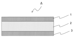
- FIG. 1 is a cross-sectional view showing a schematic configuration of a laminated structure according to this embodiment.
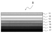
- FIG. 2 is a cross-sectional view showing a schematic configuration of the laminated structure according to this embodiment.
- this embodiment a mode for carrying out the present invention (hereinafter also referred to as “this embodiment”) will be described in detail. Note that the present invention is not limited to this embodiment, and can be implemented with various modifications within the scope of the gist.
- the object of the first embodiment is to provide a foam and a laminated structure using the foam that exhibits excellent compressive strength while utilizing biomass resources.
- the foam according to the first embodiment includes modified lignin chemically modified with polyethylene glycol.
- the modified lignin according to the first embodiment is a modified lignin chemically modified with polyethylene glycol.
- the lignin in the modified lignin is not particularly limited, but examples thereof include guaiacyl lignin (G type), syringyl lignin (S type), and p-hydroxyphenyl lignin (H type). These lignins have a basic skeleton of a polymeric phenolic compound and are contained in all plants.
- the origin of lignin is not particularly limited, but includes lignin derived from woody plants and lignin derived from herbaceous plants.
- the lignin derived from woody plants is not particularly limited, but includes, for example, coniferous lignin contained in coniferous trees (for example, cedar), and for example, hardwood lignin contained in broadleaf trees.
- Lignin derived from woody plants does not contain an H-type basic skeleton.
- coniferous lignin does not contain an S-type basic skeleton but has a G-type basic skeleton.
- hardwood lignin has a G-type basic skeleton and an S-type basic skeleton.
- lignin derived from herbaceous plants examples include rice-based lignin contained in grasses (such as wheat straw, rice straw, corn, and bamboo). Lignin derived from herbaceous plants has all basic skeletons of H type, G type, and S type. These lignins can be used alone or in combination of two or more.
- the lignin is preferably a coniferous lignin having a G-type basic skeleton, and more preferably a coniferous lignin derived from Japanese cedar.
- lignins have a basic skeleton of polymeric phenolic compounds and are contained in all plants.
- Lignin is industrially extracted, for example, when pulp is produced from plant material (lignocellulose) as a raw material by the soda method, sulfite method, kraft method, etc., and it is contained in the waste liquid (black liquor) discharged. Soda lignin, sulfite lignin, and kraft lignin are known.
- the number average molecular weight of polyethylene glycol is preferably 100 to 1000, more preferably 200 to 900, still more preferably 300 to 800, even more preferably 400 to 600. Note that the number average molecular weight can be determined as a polyethylene glycol equivalent molecular weight by gel permeation chromatography.
- the method for producing modified lignin is not particularly limited, and examples include the method described in JP 2017-197517A.
- modified lignin chemically modified with polyethylene glycol can be obtained by digesting plant material (lignocellulose), which is a raw material for lignin, using polyethylene glycol.
- the cooking method is not particularly limited, but includes, for example, a method of mixing and reacting a plant material that is a raw material for lignin, polyethylene glycol, and an inorganic acid as an acid catalyst (e.g., hydrochloric acid, sulfuric acid, etc.). .
- the blending ratio of polyethylene glycol is preferably 200 to 1000 parts by mass, more preferably 300 to 600 parts by mass, per 100 parts by mass of the plant material that is the raw material for lignin.
- the blending ratio of the inorganic acid is preferably 0.1 to 2 parts by mass, more preferably 0.2 to 1 part by mass, based on 100 parts by mass of polyethylene glycol.
- the reaction temperature is preferably 120 to 180°C, more preferably 130 to 150°C under normal pressure.
- the reaction time is preferably 60 to 240 minutes, more preferably 60 to 120 minutes.
- a known alkali for example, ammonia, sodium hydroxide, etc.
- the adjusted pH is preferably 8 to 14, more preferably 10 to 14, and still more preferably 10.5 to 14.
- pulp is obtained as a solid component
- modified lignin is obtained as a solution component (pulp waste liquid).
- reaction liquid after the reaction is completed is treated by a known separation method such as filtration, pressing, or centrifugation to separate the solid component (pulp) from the reaction product and collect the solution component (pulp waste liquid). good.
- the solid component (pulp) can be washed and the solution (modified lignin) impregnated with the solid component can be recovered.
- an inorganic acid for example, hydrochloric acid, sulfuric acid, etc.
- the pH after adjustment is preferably 5 or less, preferably 3 or less, more preferably 2 or less.
- the lower limit of the pH after adjustment is not particularly limited, but may be, for example, 1.5.
- modified lignin can be obtained as a solid content by collecting the obtained precipitate by a known method such as filtration, pressing, or centrifugation.
- the content of modified lignin is preferably 10 to 100% based on the total amount of the foam, from the viewpoint of maintaining excellent compressive strength while increasing the amount of biomass resources used. % by mass, more preferably 10 to 70% by mass, still more preferably 10 to 60% by mass.
- the foam according to the first embodiment preferably contains resin.
- the resin include, but are not limited to, phenol resins, epoxy resins, cyanate ester resins, and urethane resins. Among these, it is preferable to include an epoxy resin and/or a phenol resin from the viewpoint of increasing compressive strength and compressive modulus.
- the foam according to the first embodiment contains an epoxy resin
- the foam may contain a cured product of a curable resin composition containing modified lignin, an epoxy resin, and a curing agent.
- the epoxy resin according to the first embodiment is preferably an epoxy resin having two or more epoxy groups in one molecule.
- the epoxy resin include, but are not particularly limited to, glycidyl ether type epoxy resins, glycidyl amine type epoxy resins, glycidyl ester type epoxy resins, and the like.
- Epoxy resins are classified into various epoxy resins depending on the main skeleton, and in each of the above types of epoxy resins, there are also bisphenol type epoxy resins such as bisphenol A type epoxy resin, bisphenol F type epoxy resin, bisphenol S type epoxy resin, etc.
- Epoxy resin alicyclic epoxy resin such as dicyclopentadiene epoxy resin; aliphatic chain epoxy resin; phenol novolak epoxy resin, cresol novolac epoxy resin, bisphenol A novolak epoxy resin, bisphenol F novolak epoxy resin, Novolac type epoxy resins such as phenol aralkyl novolak type epoxy resins and biphenylaralkyl novolac type epoxy resins; stilbene type epoxy resins; naphthalene skeleton-containing type epoxy resins such as naphthol novolac type epoxy resins and naphthol aralkyl type epoxy resins; biphenyl type epoxy resins; Examples include xylylene type epoxy resin; dihydroanthracene type epoxy resin. When using an epoxy resin, a curing agent, a curing aid, etc. for the epoxy resin may be used in combination, if necessary.
- the blending amount of the epoxy resin is preferably 0 to 90 mass based on the total amount of the foam, from the viewpoint of increasing the usage of biomass resources and maintaining excellent compressive strength. %, more preferably 5 to 85% by mass, and even more preferably 10 to 80% by mass.
- the curable composition according to the first embodiment preferably contains a curing agent.
- the curing agent is not particularly limited as long as it can cure the epoxy resin, but examples include aminophenylsulfone curing agents, dicyandiamide curing agents, aromatic amine curing agents, halogenated boron amine complexes, and others.
- Amine curing agents such as amine curing agents, urea curing agents, imidazole curing agents, thiol curing agents, other amine curing agents, acid anhydrides, boron chloride amine complexes, etc. can be used.
- amine curing agents are preferred, at least one selected from aminophenylsulfone curing agents, dicyandiamide curing agents, aromatic amine curing agents, and halogenated boron amine complexes, and aminophenylsulfone curing agents are preferred.
- a curing agent or a dicyandiamide curing agent is more preferred.
- the blending amount of the curing agent in the curable resin composition according to the present embodiment is such that the number of moles of active hydrogen in the curing agent is 0.4 to 1 times the total number of moles of epoxy groups possessed by the epoxy resin. is preferable, and more preferably 0.5 to 0.8 times.
- the amount of the amine curing agent in the curable resin composition according to the first embodiment is such that the number of moles of active hydrogen in the amine curing agent is 0.4 with respect to the total number of moles of epoxy groups in the epoxy resin. It is preferably 1 to 1 times, more preferably 0.5 to 0.8 times.
- dicyandiamide curing agents examples include DICY7, DICY15 (manufactured by Mitsubishi Chemical Corporation), and DICYANEX1400F (manufactured by Air Products).
- the aromatic amine curing agent is preferably an aromatic polyamine.
- the aromatic amine curing agent include, but are not limited to, 3,3'-diisopropyl-4,4'-diaminodiphenylmethane, 3,3'-di-t-butyl-4,4'-diaminodiphenylmethane, 3,3'-diethyl-5,5'-dimethyl-4,4'-diaminodiphenylmethane, 3,3'-diisopropyl-5,5'-dimethyl-4,4'-diaminodiphenylmethane, 3,3'-dimethyl -t-butyl-5,5'-dimethyl-4,4'-diaminodiphenylmethane, 3,3',5,5'-tetraethyl-4,4'-diaminodiphenylmethane, 3,3'-diisopropyl-5,5 '-Dieth
- halogenated boron amine complex examples include boron trifluoride aniline complex, boron trifluoride p-chloroaniline complex, boron trifluoride ethylamine complex, boron trifluoride isopropylamine complex, boron trifluoride benzylamine complex, Boron trifluoride dimethylamine complex, boron trifluoride diethylamine complex, boron trifluoride dibutylamine complex, boron trifluoride piperidine complex, boron trifluoride dibenzylamine complex, boron trichloride aniline complex, boron trichloride p- Chloroaniline complex, boron trichloride ethylamine complex, boron trichloride isopropylamine complex, boron trichloride benzylamine complex, boron trichloride dimethylamine complex, boron trichloride diethylamine complex
- the urea-based curing agent is not particularly limited as long as it has a dimethylureido group in its molecule and generates an isocyanate group and dimethylamine by heating at high temperature, and these activate the epoxy group, but for example, Examples include aromatic dimethylurea in which a dimethylureido group is bonded to an aromatic ring, and aliphatic dimethylurea in which a dimethylureido group is bonded to an aliphatic compound.
- imidazole curing agent examples include, but are not limited to, imidazole adducts, clathrate imidazoles, microcapsule imidazole, imidazole compounds coordinated with stabilizers, and the like.
- the thiol-based curing agent is not particularly limited, but examples thereof include pentaerythritol tetrakis (3-mercaptobutyrate), polyether-based resins having a thiol group, and the like.
- Commercially available thiol curing agents include, for example, Karenz MT PE1 (manufactured by Showa Denko Co., Ltd.) and Polythiol QE-340M (Toray Fine Chemical Co., Ltd.).
- the curable composition according to the first embodiment preferably contains a curing accelerator.
- the curing accelerator include, but are not limited to, halogenated boron amine complex curing accelerators, aromatic urea curing accelerators, imidazole curing accelerators, and phosphorus curing accelerators. Among these, it is preferable to include a halogenated boron amine complex type curing accelerator or an aromatic urea type curing accelerator.
- halogenated boron amine complex curing accelerator examples include boron trifluoride aniline complex, boron trifluoride p-chloroaniline complex, boron trifluoride ethylamine complex, boron trifluoride isopropylamine complex, and boron trifluoride.
- Benzylamine complex boron trifluoride dimethylamine complex, boron trifluoride diethylamine complex, boron trifluoride dibutylamine complex, boron trifluoride piperidine complex, boron trifluoride dibenzylamine complex, boron trichloride aniline complex, Boron chloride p-chloroaniline complex, boron trichloride ethylamine complex, boron trichloride isopropylamine complex, boron trichloride benzylamine complex, boron trichloride dimethylamine complex, boron trichloride diethylamine complex, boron trichloride dibutylamine complex, trichloride Examples include boron piperidine complex, boron trichloride dibenzylamine complex, and boron trichloride-N,N-dimethyloctylamine complex.
- the curing accelerator is preferably a boron fluoride amine complex type curing accelerator such as a boron trifluoride diethylamine complex, a boron trifluoride dibutylamine complex, a boron trifluoride piperidine complex, or a boron trifluoride dibenzylamine complex.
- the halogenated boron amine complex may also function as a curing agent as described above.
- the curing accelerator is preferably not a halogenated boron amine complex type curing accelerator.
- the aromatic urea-based curing accelerator is not particularly limited, but includes, for example, 3-phenyl-1,1-dimethylurea, 3-(3-chloro-4-methylphenyl)-1,1-dimethylurea, 3- Examples include (3,4-dichlorophenyl)-1,1-dimethylurea and toluene bisdimethylurea.
- Commercially available aromatic urea curing accelerators include DCMU-99 (manufactured by Hodogaya Chemical Industry Co., Ltd.) and "Omicure (registered trademark)" 24 (manufactured by PTI Japan Co., Ltd.). It will be done.
- the imidazole curing accelerator is not particularly limited, but examples include 1-benzyl-2-methylimidazole, 1-benzyl-2-ethylimidazole, 1-cyanoethyl-2-methylimidazole, 1-cyanoethyl-2-ethyl- Examples include 4-methylimidazole and 1-cyanoethyl-2-phenylimidazole.
- Commercially available imidazole curing accelerators include "Cure Duct (registered trademark)" P-0505, 1B2MZ, 1B2PZ, 2MZ-CN, 2E4MZ-CN, 2PZ-CN (manufactured by Shikoku Kasei Kogyo Co., Ltd.), etc. can be mentioned.
- Phosphorous curing accelerators include, but are not particularly limited to, triphenylphosphine, tri-o-tolylphosphine, tris(p-methoxyphenyl)phosphine, triphenylphosphine triphenylborane, tetraphenylphosphonium tetraphenylborate, and the like. Can be mentioned.
- commercial products of phosphorus compounds include “Hokuko TPP (registered trademark),” “TOTP (registered trademark),” “TPP-K (registered trademark)” (manufactured by Hokuko Chemical Industry Co., Ltd.), etc. It will be done.
- the blending amount of the curing accelerator is preferably 1 to 8 parts by weight, more preferably 1.5 to 6 parts by weight, and still more preferably 2 to 4 parts by weight, based on 100 parts by weight of the epoxy resin.
- Phenol resin is, for example, a resol type phenol obtained by reacting a phenol compound or its derivative and an aldehyde compound under an alkali catalyst, a phenol compound or its derivative, and an aldehyde compound as raw materials. Examples include novolac phenols obtained by reacting phenols under an acid catalyst. Examples of the phenol compound include, but are not limited to, phenol, cresol, xylenol, para-alkylphenol, para-phenylphenol, resorcinol, and the like. Examples of the aldehyde compound include, but are not limited to, formaldehyde, paraformaldehyde, furfural, acetaldehyde, and the like.
- the blending amount of the phenol resin is preferably 0 to 90 mass based on the total amount of the foam, from the viewpoint of maintaining excellent compressive strength while increasing the amount of biomass resources used. %, more preferably 5 to 85% by mass, and even more preferably 10 to 80% by mass.
- an epoxy resin and a phenol resin may be used together.
- the total amount of epoxy resin and phenol resin in the foam according to this embodiment is preferably determined based on the total amount of the foam from the viewpoint of maintaining excellent compressive strength while increasing the amount of biomass resources used. is 0 to 90% by mass, more preferably 5 to 85% by mass, and still more preferably 10 to 80% by mass.
- foaming agent for example, a foaming agent that foams when heated may be used.
- blowing agents include, but are not limited to, azo compounds such as azodicarbonamide, azodicarboxylic acid metal salts (barium azodicarboxylate, etc.), azobisisobutyronitrile, and N,N'-dinitrosopentamethylene.
- Nitroso compounds such as tetramine, hydrazodicarbonamide, 4,4'-oxybis(benzenesulfonyl hydrazide), hydrazine derivatives such as toluenesulfonyl hydrazide, semicarbazide compounds such as toluenesulfonyl semicarbazide, ammonium carbonate, sodium carbonate, ammonium bicarbonate, carbonic acid Examples include sodium hydrogen, ammonium nitrite, sodium borohydride, anhydrous monosodium citrate, and thermally expandable microcapsules. Thermally expandable microcapsules, for example, encapsulate a volatile liquid in a thermoplastic polymer shell.
- the amount of the blowing agent may be 1 to 80 parts by mass based on 100 parts by mass of the total amount of modified lignin and resin.
- the density of the foam according to the first embodiment is preferably 40 to 600 Kg/m 3 , more preferably 50 to 400 Kg/m 3 , and preferably 60 to 300 Kg/m 3 .
- the compression modulus of the foam according to the first embodiment according to the JIS K 7220:2006 compression test is preferably 20 to 80 MPa, more preferably 30 to 75 MPa, and even more preferably 40 to 70 MPa.
- the compression modulus was measured by the method described in Examples.
- the compressive strength of the foam according to the first embodiment in the JIS K 7220:2006 compression test is preferably 0.4 to 2.0 MPa, more preferably 0.5 to 1.8 MPa, and even more preferably is 0.6 to 1.5 MPa.
- the compressive strength was measured by the method described in Examples.
- the foam according to the first embodiment is preferably biodegradable.
- the modified lignin contained in the foam according to this embodiment exhibits biodegradability. Whether or not it exhibits biodegradability can be determined by whether or not cracks occur after being left for 150 days in the presence of white rot fungi at a temperature of 23° C. and a humidity of 50 to 60%.
- a test piece of 50 mm x 50 mm x 2 mm is cut out from the cured product, placed in a mycelium bottle containing white rot fungi, and left to stand for 150 days at a temperature of 23°C and a humidity of 50 to 60%. After standing, the test piece was cut with a cutting machine equipped with a diamond blade (Labo Cutter "MC-120", manufactured by Maruto Co., Ltd.), and then the cross section was cut with a polisher (manufactured by IM-T Co., Ltd., tabletop sample polishing machine "IM-120").
- the foam according to this embodiment is obtained by mixing a resin component containing modified lignin with a foaming agent, filling the mixture into a mold, and heating and curing the mixture.
- the heating temperature is not particularly limited, but may be, for example, 50 to 200°C.
- the object of the second embodiment is to provide a foam and a laminated structure using the foam that has excellent radio wave absorption properties while utilizing biomass resources.
- the foam according to the second embodiment includes modified lignin and a conductive material.
- the factors for obtaining such characteristics are not particularly limited, but are thought to be as follows.
- radio wave absorption becomes possible by adding a conductive material such as carbon black and controlling the real part and imaginary part of the complex dielectric constant.
- a conductive material such as carbon black
- the amount of conductive material such as carbon black added there is a limit to the amount of conductive material such as carbon black added, and it has been difficult to obtain the desired real and imaginary parts of the complex dielectric constant.
- the value of the imaginary part depends on the amount of conductive material added, and it has been difficult to obtain the desired value of the imaginary part with the addition of a small amount of conductive material. For example, it was found that by including modified lignin, the desired imaginary part value could be obtained even if the amount of conductive material added was small.
- the foam according to the second embodiment is basically the same as the foam according to the first embodiment described above except that it contains a conductive material.
- explanations are omitted for parts having common configurations with the foam according to the first embodiment, and explanations are given for configurations different from the foam according to the first embodiment. do.
- conductive material examples include conductive carbon such as carbon black, graphene, carbon nanotubes, carbon nanofibers, carbon microfibers, carbon microcoils, and carbon nanocoils, conductive fibers such as metal fibers and carbon fibers, and iron oxide. , tin oxide, titanium oxide, zinc oxide, cadmium oxide, iridium oxide, and other conductive inorganic oxides. Among these, conductive carbon is preferred, and carbon black is more preferred.
- carbon black examples include, but are not particularly limited to, oil furnace black, acetylene black, and those obtained by making these oil furnace blacks or acetylene blacks hydrophilic, hydrophobic, oxidized, reduced, acidified, basicized, or organically treated. can be mentioned.
- the content of carbon black in the foam according to the second embodiment is preferably 1 to 30% by mass, more preferably 2 to 20% by mass, still more preferably 3 to 30% by mass, based on the total amount of the foam. It is 15% by mass.
- the modified lignin in the foam according to the second embodiment preferably includes modified lignin chemically modified with polyethylene glycol.
- the modified lignin chemically modified with polyethylene glycol is as described above.
- the content of modified lignin in the foam according to the second embodiment is preferably 10 to 99% by mass, more preferably 20 to 99% by mass, based on the total amount of the foam, from the viewpoint of further improving radio wave absorption characteristics. ⁇ 98% by weight, more preferably 30 ⁇ 98% by weight, even more preferably 60 ⁇ 97% by weight, still more preferably 70 ⁇ 97% by weight.
- the foam according to the second embodiment may contain resin.
- the resin includes a phenolic resin.
- the resin content in the foam according to the second embodiment is preferably 1 to 89% by mass, more preferably 2 to 87% by mass, and preferably 15 to 85% by mass, based on the total amount of the foam. Mass%.
- the content of modified lignin is preferably 10 to 99% by mass, more preferably 20 to 80% by mass, based on the total amount of the foam. and preferably 30 to 70% by mass.
- the expansion ratio of the foam according to the second embodiment is preferably 2 to 20 times, more preferably 3 to 15 times, and preferably 3 to 10 times.
- the foam according to this embodiment is preferably biodegradable.
- the modified lignin contained in the foam according to this embodiment exhibits biodegradability. Whether or not it exhibits biodegradability can be determined by whether or not biodegradation is confirmed after being left in the presence of white rot fungi at a temperature of 23° C. and a humidity of 50 to 60% for 150 days.
- the determination is made by the method shown below. Cut a test piece of 50 mm x 50 mm x 2 mm from the foam, place it in a mycelium bottle containing white rot fungi, and leave it for 150 days at a temperature of 23°C and a humidity of 50 to 60%. After standing, the test piece was cut with a cutting machine equipped with a diamond blade (Labo Cutter "MC-120", manufactured by Maruto Co., Ltd.), and then the cross section was cut with a polisher (manufactured by IM-T Co., Ltd., tabletop sample polishing machine "IM-120").
- the foam according to the second embodiment has excellent radio wave absorption properties and is therefore used as a radio wave absorber.
- FIG. 1 is a cross-sectional view showing a schematic configuration of a laminated structure A according to this embodiment.
- the laminated structure A according to the present embodiment includes a first fiber-reinforced resin layer (1) containing resin and fibers, and a foam layer (2) containing the foam according to the present embodiment. and a second fiber-reinforced resin layer (3) containing resin and fibers in this order.
- the laminated structure A according to the present embodiment has the configuration and exhibits excellent mechanical properties while utilizing modified lignin, which is a biomass resource.
- the foam layer includes the foam according to the present embodiment described above. Examples and preferred examples of various components are as described above.
- the first fiber-reinforced resin layer and the second fiber-reinforced resin layer contain resin and fibers.
- the resin include, but are not limited to, epoxy resins, phenol resins, cyanate ester resins, unsaturated polyester resins, and vinyl ester resins.
- fibers include carbon fibers, glass fibers, organic fibers, and natural fibers.
- the first fiber-reinforced resin layer and the second fiber-reinforced resin layer preferably include a cured product of a curable resin composition containing an epoxy resin, modified lignin chemically modified with polyethylene glycol, and fibers.
- the epoxy resin, modified lignin, and fiber are as exemplified above.
- the foam and laminated structure according to this embodiment can be widely used in aerospace applications, general industrial applications such as automobiles, ships, and railway vehicles, and sports applications.
- the laminated structure B according to this embodiment functions as a layered structure for absorbing radio waves.
- the laminated structure B according to the present embodiment has a plurality of laminated layers made of the foam according to the second embodiment (hereinafter also referred to as "foam layers"), and the conductive material in the plurality of layers is laminated. The contents are configured to be different from each other.
- the foam layer includes the foam according to the second embodiment described above. Examples and preferred examples of various components are as described above.
- the laminated structure B according to this embodiment is The n-th layer from the outermost layer side is defined as the n-th layer, the content of the conductive material in the n-th layer is defined as A n , and the n-1th layer is defined as the n-1th layer, and the When the content of the conductive material in the n-1th layer is A n-1 , It is preferable that the following relational expression (1) be satisfied for any n.
- a n-1 ⁇ A n (1) In the formula, n is an integer greater than or equal to 2 and less than or equal to the number of laminated layers made of the foam.)
- the total number of layers made of foam in the laminated structure B is not particularly limited, but may be, for example, 2 to 20 layers, 3 to 18 layers, or 3 to 15 layers. good.
- FIG. 2 is a cross-sectional view showing a schematic configuration of the laminated structure B according to the present embodiment.
- the laminated structure B according to the present embodiment includes a foam layer 11 with a conductive material content of 0% by mass, a foam layer 12 with a conductive material content of 1% by mass, a conductive material
- the foam layer 13 includes a foam layer 13 having a content of 5% by mass, a foam layer 14 having a conductive material content of 10% by mass, and a foam layer 15 having a conductive material content of 20% by mass in this order.
- the content of the conductive material increases from the foam layer 11 to the lower layers.
- the foam layer 11 is the first layer
- the foam layer 11 is 0% by mass, based on the foam layer 12 corresponding to the second layer.
- the foam layer 14 satisfies the above-mentioned relational expression (1) and corresponds to the fourth layer, then the foam layer 14 is 10% by mass.
- the laminated structure B according to this embodiment is used for radio wave absorption purposes, and is used as a material for a radio wave anechoic chamber.
- compression test A compression test was conducted in accordance with JIS K 7164:2005. A test piece was created from the foam, sandwiched between two smooth and parallel circular pressure plates, and a constant speed compression test was performed on the columnar test piece in the axial direction to calculate the amount of deformation, elastic modulus, and strength. . The compression test was conducted under the following conditions. ⁇ Test conditions> Crosshead speed: 1-10mm/min Deformation measurement method: Calculated from crosshead movement amount Test piece size: Shape: Rectangular parallelepiped Bottom: 100 x 100 mm Thickness: 50mm
- the complex dielectric constant of the foam was measured using a complex dielectric constant measuring device.
- the complex dielectric constant measuring device mainly consists of a pair of horn antennas with lenses, a network analyzer, and a communication line. A pair of lens-equipped horn antennas are arranged to face each other, and a radio wave absorber to be measured is installed between the pair of lens-equipped horn antennas.
- this network analyzer transmits a control signal to the lens-equipped horn antenna via the communication line, converts the signal transmitted from the lens-equipped horn antenna via the communication line into digital data, and then converts the digital data into Nicholson -
- the complex dielectric constant of the radio wave absorber was calculated using an algorithm for estimating material constants called the Ross method or the NIST method. To measure the complex dielectric constant of the foam, first, we regarded the space between a pair of lensed horn antennas as a transmission path, and measured the transmission characteristics of the transmission path when no radio wave absorber was installed, that is, air.
- a radio wave absorber is installed, and the complex relative permittivity of the radio wave absorber is calculated by determining the material constant based on the transmission characteristics of air using the lens antenna method from the radio wave reflection and transmission characteristics by the radio wave absorber SP. did.
- the measurement range was from 18 GHz to 26.5 GHz, and the complex dielectric constant of the foam was measured.
- Example 1 Production of modified lignin foam
- a blowing agent was further mixed and stirred, the mixture was filled into a mold, and cured at 80 to 130°C for 30 minutes.
- a foam having a density of 120 Kg/m 3 (equivalent to approximately 10 times foaming) was produced.
- Table 1 shows the results of the compression test conducted using the method described above.
- Example 2 Production of modified lignin foam
- a foam was produced in the same manner as in Example 1 except that the modified lignin and epoxy resin were used in a mass ratio of 50:50.
- Table 1 shows the results of the compression test conducted using the method described above.
- Example 3 Production of modified lignin foam
- a foaming agent was mixed and stirred with the modified lignin, filled into a mold, and cured at 80 to 130°C for 30 minutes to produce a foam with a density of 120 Kg/m 3 (equivalent to approximately 10 times foaming).
- Table 1 shows the results of the compression test conducted using the method described above.
- Example 4 Production of modified lignin foam
- a blowing agent was further mixed and stirred, filled into a mold, and cured at 80 to 130°C for 30 minutes, resulting in a density of 120 kg/m 3 ( A foam with a foaming capacity of approximately 10 times the foaming was produced.
- Table 2 shows the results of the compression test conducted using the method described above.
- Example 5 Production of modified lignin foam
- a foam was produced in the same manner as in Example 4 except that the modified lignin and phenolic resin were used in a mass ratio of 50:50.
- Table 2 shows the results of the compression test conducted using the method described above.
- Example 6 Production of modified lignin foam
- a foam was produced in the same manner as in Example 4 except that the modified lignin and phenolic resin were used in a mass ratio of 75:25.
- Table 2 shows the results of the compression test conducted using the method described above. Note that in Table 2, information on Example 3 is shown for reference.
- Example 7 Production of modified lignin foam
- a blowing agent was further mixed and stirred, filled into a mold, and cured at 80 to 180°C for 60 minutes, resulting in a density of 120 Kg/m 3 ( A foam with a foaming capacity of approximately 10 times the foaming was produced.
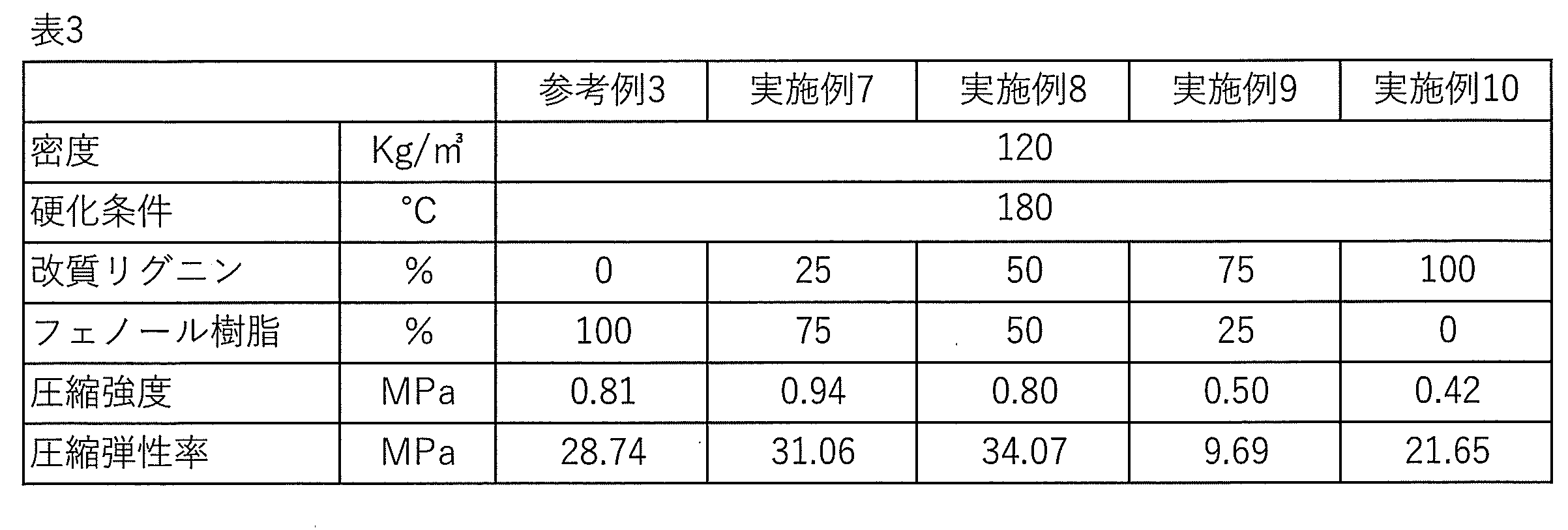
- Table 3 shows the results of the compression test conducted using the method described above.
- Example 8 Production of modified lignin foam
- a foam was produced in the same manner as in Example 7 except that the modified lignin and phenolic resin were used in a mass ratio of 50:50.
- Table 3 shows the results of the compression test conducted using the method described above.
- Example 9 Production of modified lignin foam
- a foam was produced in the same manner as in Example 7 except that the modified lignin and phenolic resin were used in a mass ratio of 75:25.
- Table 3 shows the results of the compression test conducted using the method described above.
- Example 10 Production of modified lignin foam
- a foaming agent was mixed and stirred with the modified lignin, filled into a mold, and cured at 80 to 180° C. for 60 minutes to produce a foam with a density of 120 Kg/m 3 (equivalent to approximately 10 times foaming).
- Table 3 shows the results of the compression test conducted using the method described above.
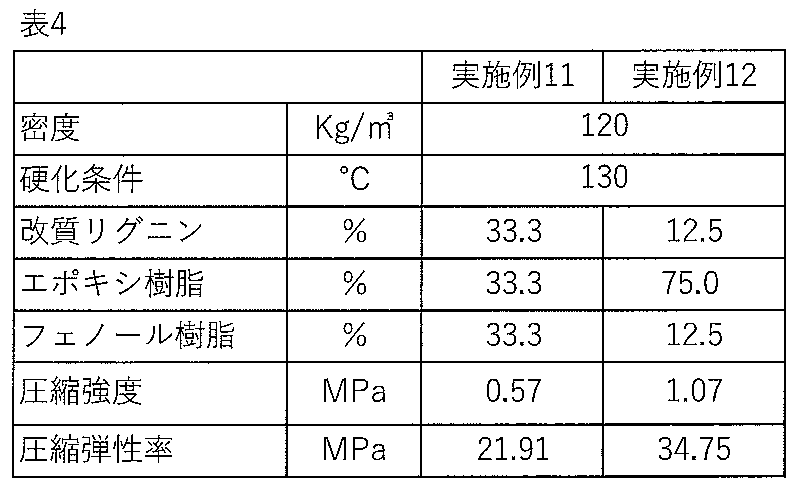
- Example 11 Production of modified lignin foam
- a blowing agent is further mixed and stirred, and the mixture is filled into a mold and heated at 80 to 130°C.
- the foam was cured for 30 minutes to produce a foam having a density of 120 kg/m 3 (equivalent to approximately 10 times foaming).
- Table 4 shows the results of the compression test conducted using the method described above.
- Example 12 Production of modified lignin foam
- a foam was produced in the same manner as in Example 11 except that the modified lignin, epoxy resin, and phenol resin were used in a mass ratio of 12.5:75:12.5.
- Table 4 shows the results of the compression test conducted using the method described above.
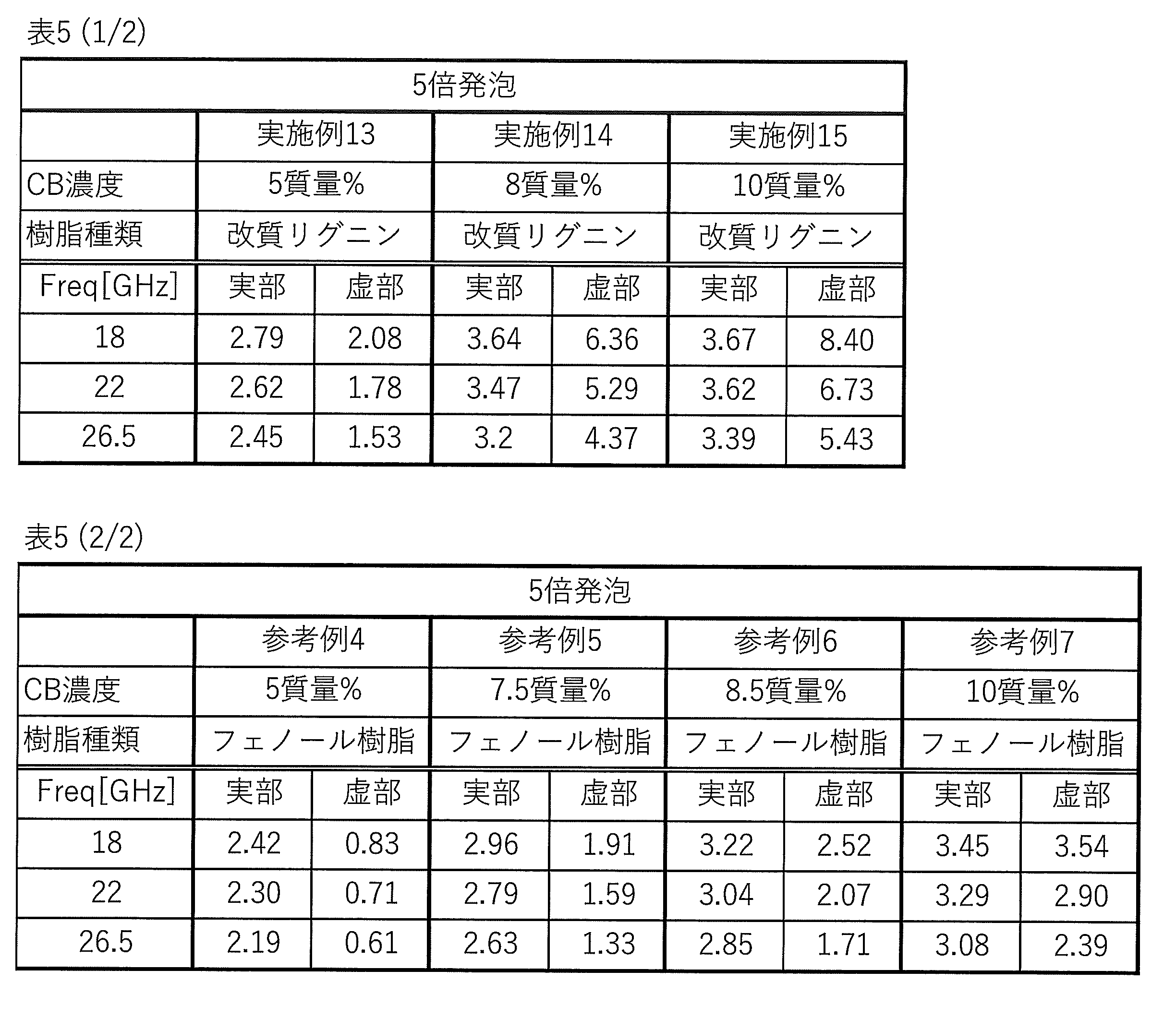
- Example 13 Production of foam containing conductive material
- a blowing agent was further mixed and stirred, filled into a mold, and cured at 80 to 130 ° C. for 30 minutes.
- a foam having a density of 240 Kg/m 3 (equivalent to approximately 5 times foaming) was produced.
- Example 14 to 15 Production of foam containing conductive material
- Foams of Examples 14 and 15 were produced in the same manner as in Example 13, except that the blending ratio of carbon black was changed to 8% by mass and 10% by mass.
- Reference Examples 5 to 7 Production of foam containing conductive material
- Foams of Reference Examples 5 to 7 were produced by the same method as that shown in Reference Example 4, except that the blending ratio of carbon black was changed to 7.5% by mass, 8.5% by mass, and 10% by mass. was created.
- the evaluation results of the Examples containing phenolic resin and modified lignin have a higher real part and imaginary part than the evaluation results of the Reference Examples that do not contain modified lignin. It can be seen that improvements in characteristics can be seen in both results.
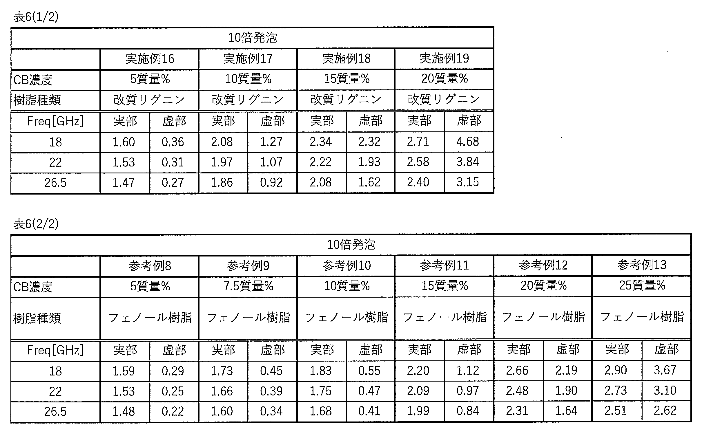
- Example 16 Production of foam containing conductive material
- a foam was produced in the same manner as in Example 13, except that the amount of foaming agent added was changed and the expansion ratio was approximately 10 times.
- Example 17 to 19 Production of foam containing conductive material
- Foams of Examples 17 to 19 were produced in the same manner as in Example 16, except that the blending ratio of carbon black was changed to 10% by mass, 15% by mass, and 20% by mass.
- Reference example 9 to 13 Production of foam containing conductive material
- Reference example was prepared in the same manner as in Reference example 8, except that the blending ratio of carbon black was changed to 7.5% by mass, 10% by mass, 15% by mass, 20% by mass, and 25% by mass. 9 to 13 foams were made.
- the evaluation results of the Examples containing phenolic resin and modified lignin have a higher real part and imaginary part than the evaluation results of the Reference Examples that do not contain modified lignin. It can be seen that improvements in characteristics can be seen in both results.
- A, B Laminated structure 1: First fiber reinforced resin layer 2: Foam layer 3: Second fiber reinforced resin layer 11: Foam layer with conductive material content of 0% by mass 12: Containing conductive material 13: Foam layer with a conductive material content of 5% by mass 14: Foam layer with a conductive material content of 10% by mass 15: Foam layer with a conductive material content of 20% by mass foam layer
Landscapes
- Chemical & Material Sciences (AREA)
- Engineering & Computer Science (AREA)
- Materials Engineering (AREA)
- Health & Medical Sciences (AREA)
- Chemical Kinetics & Catalysis (AREA)
- Medicinal Chemistry (AREA)
- Polymers & Plastics (AREA)
- Organic Chemistry (AREA)
- Inorganic Chemistry (AREA)
- Laminated Bodies (AREA)
Abstract
Description
<1>
ポリエチレングリコールにより化学修飾された改質リグニンを含む、発泡体。
<2>
樹脂を更に含む、<1>に記載の発泡体。
<3>
前記樹脂が、フェノール樹脂、エポキシ樹脂、シアネートエステル樹脂、及びウレタン樹脂からなる群から選ばれる少なくとも1種を含む、<2>に記載の発泡体。
<4>
前記樹脂が、フェノール樹脂を含む、<2>又は<3>に記載の発泡体。
<5>
前記樹脂が、エポキシ樹脂を含む、<2>~<4>のいずれかに記載の発泡体。
<6>
前記改質リグニン、エポキシ樹脂及び硬化剤を含む硬化性樹脂組成物の硬化物を含む、<5>に記載の発泡体。
<7>
前記改質リグニンの含有量が、発泡体全量に対して、10~60質量%である、<1>~<6>のいずれかに記載の発泡体。
<8>
JIS K 7220:2006の圧縮試験による圧縮弾性率が、20~80MPaである、<1>~<7>のいずれかに記載の発泡体。
<9>
JIS K 7220:2006の圧縮試験における圧縮強度が、0.4~2.0MPaである、<1>~<8>のいずれかに記載の発泡体。
<10>
樹脂、及び繊維を含有する第1繊維強化樹脂層と、
<1>~<9>のいずれかに記載の発泡体を含む発泡体層と、
樹脂、及び繊維を含有する第2繊維強化樹脂層と、
をこの順で有する、積層構造体。
<11>
前記第1繊維強化樹脂層及び前記第2繊維強化樹脂層が、ポリエチレングリコールにより化学修飾された改質リグニンを含む、<10>に記載の積層構造体。
<12>
改質リグニン、及び導電性材料を含む、発泡体。
<13>
前記改質リグニンが、ポリエチレングリコールにより化学修飾された改質リグニンを含む、<12>に記載の発泡体。
<14>
前記改質リグニンの含有量が、発泡体全量に対して、10~99質量%である、<12>又は<13>に記載の発泡体。
<15>
前記導電性材料が、導電性カーボンである、<12>~<14>のいずれかに記載の発泡体。
<16>
前記導電性材料が、カーボンブラックである、<12>~<15>のいずれかに記載の発泡体。
<17>
前記導電性材料の含有量が、発泡体全量に対して、1~30質量%である、<12>~<16>のいずれかに記載の発泡体。
<18>
前記発泡体の発泡倍率が、2~20倍である、<12>~<17>のいずれかに記載の発泡体。
<19>
樹脂を更に含む、<12>~<18>のいずれかに記載の発泡体。
<20>
前記樹脂が、フェノール樹脂を含む、<19>に記載の発泡体。
<21>
前記樹脂の含有量が、発泡体全量に対して、1~89質量%である、<19>に記載の発泡体。
<22>
生分解性である、<1>~<9>、及び<12>~<21>のいずれかに記載の発泡体。
<23>
<12>~<22>のいずれか一項に記載の発泡体からなる層が複数積層され、
複数の前記層における、前記導電性材料の含有量が、互いに異なる、積層構造体。
<24>
最表層側からn番目の前記層を第n層とし、前記第n層における前記導電性材料の含有量をAnとし、且つ、n-1番目の前記層を第n-1層とし、前記第n-1層における前記導電性材料の含有量をAn-1としたとき、
任意のnにおいて以下の関係式(1)を満たす、<23>に記載の積層構造体。
An-1<An (1)
(式中、nは、2以上、且つ、前記発泡体からなる層の積層数以下の整数である。)
<25>
電波吸収用である、<23>又は<24>に記載の積層構造体。
(第1の実施形態)
特許文献2に示されるように、改質リグニンを用いる繊維強化樹脂は知られているが、リグニンを用いる発泡体は知られていない。
第1の実施形態に係る改質リグニンは、ポリエチレングリコールにより化学修飾された改質リグニンである。
これらのリグニンは、単独使用または2種類以上併用することができる。
第1の実施形態に係る発泡体は、樹脂を含むことが好ましい。樹脂を含むことで、発泡体の機械的強度を高めることができ、圧縮強度及び圧縮弾性率が高められる。
樹脂としては、特に限定されないが、フェノール樹脂、エポキシ樹脂、シアネートエステル樹脂、及びウレタン樹脂が挙げられる。これらの中でも、圧縮強度及び圧縮弾性率を高める観点から、エポキシ樹脂、及び/又はフェノール樹脂を含むことが好ましい。
第1の実施形態に係る発泡体がエポキシ樹脂を含む場合、発泡体は、改質リグニン、エポキシ樹脂及び硬化剤を含む硬化性樹脂組成物の硬化物を含んでいてもよい。
エポキシ樹脂は、主骨格の違いによっても種々のエポキシ樹脂に分類され、上記それぞれのタイプのエポキシ樹脂において、さらに、ビスフェノールA型エポキシ樹脂、ビスフェノールF型エポキシ樹脂、ビスフェノールS型エポキシ樹脂等のビスフェノール型エポキシ樹脂;ジシクロペンタジエン型エポキシ樹脂等の脂環式エポキシ樹脂;脂肪族鎖状エポキシ樹脂;フェノールノボラック型エポキシ樹脂、クレゾールノボラック型エポキシ樹脂、ビスフェノールAノボラック型エポキシ樹脂、ビスフェノールFノボラック型エポキシ樹脂、フェノールアラルキルノボラック型エポキシ樹脂、ビフェニルアラルキルノボラック型エポキシ樹脂等のノボラック型エポキシ樹脂;スチルベン型エポキシ樹脂;ナフトールノボラック型エポキシ樹脂、ナフトールアラルキル型エポキシ樹脂等のナフタレン骨格含有型エポキシ樹脂;ビフェニル型エポキシ樹脂;キシリレン型エポキシ樹脂;ジヒドロアントラセン型エポキシ樹脂が挙げられる。
エポキシ樹脂を用いる場合、必要に応じて、エポキシ樹脂の硬化剤、硬化助剤等を併用してもよい。
第1の実施形態に係る硬化性組成物は、硬化剤を含むことが好ましい。硬化剤としては、エポキシ樹脂を硬化することが可能であれば特に制限されないが、例えば、アミノフェニルスルホン系硬化剤、ジシアンジアミド系硬化剤、芳香族アミン系硬化剤、ハロゲン化ホウ素アミン錯体、及びその他アミン系硬化剤等のアミン系硬化剤、ウレア系硬化剤、イミダゾール系硬化剤、チオール系硬化剤、その他アミン系硬化剤、酸無水物、塩化ホウ素アミン錯体等を用いることができる。これらの中でも、アミン系硬化剤が好ましく、アミノフェニルスルホン系硬化剤、ジシアンジアミド系硬化剤、芳香族アミン系硬化剤、及びハロゲン化ホウ素アミン錯体から選ばれる少なくとも1種がより好ましく、アミノフェニルスルホン系硬化剤、又はジシアンジアミド系硬化剤が更に好ましい。
第1の実施形態に係る硬化性組成物は、硬化促進剤を含むことが好ましい。硬化促進剤としては、特に限定されないが、例えば、ハロゲン化ホウ素アミン錯体系硬化促進剤、芳香族ウレア系硬化促進剤、イミダゾール系硬化促進剤、リン系硬化促進剤が挙げられる。これらの中でも、ハロゲン化ホウ素アミン錯体系硬化促進剤、又は芳香族ウレア系硬化促進剤を含むことが好ましい。
なお、ハロゲン化ホウ素アミン錯体は、前述のとおり硬化剤としても機能することがある。硬化剤として、ハロゲン化ホウ素アミン錯体を含む場合、硬化促進剤は、ハロゲン化ホウ素アミン錯体系硬化促進剤でないことが好ましい。
フェノール樹脂は、例えば、フェノール化合物若しくはその誘導体と、アルデヒド化合物とを原料とし、それらをアルカリ触媒下で反応して得られるレゾール系フェノール、フェノール化合物若しくはその誘導体と、アルデヒド化合物とを原料とし、それらを酸触媒下で反応して得られるノボラック系フェノールが挙げられる。フェノール化合物としては、特に限定されないが、例えば、フェノール、クレゾール、キシレノール、パラアルキルフェノール、パラフェニルフェノール、レゾルシン等が挙げられる。アルデヒド化合物としては、特に限定されないが、例えば、ホルムアルデヒド、パラホルムアルデヒド、フルフラール、アセトアルデヒド等が挙げられる。
発泡剤として、例えば、加熱により発泡する発泡剤を用いてもよい。
発泡剤としては、特に限定さないが、例えば、アゾジカルボンアミド、アゾジカルボン酸金属塩(アゾジカルボン酸バリウム等)、アゾビスイソブチロニトリル等のアゾ化合物、N,N'-ジニトロソペンタメチレンテトラミン等のニトロソ化合物、ヒドラゾジカルボンアミド、4,4’-オキシビス(ベンゼンスルホニルヒドラジド)、トルエンスルホニルヒドラジド等のヒドラジン誘導体、トルエンスルホニルセミカルバジド等のセミカルバジド化合物、炭酸アンモニウム、炭酸ナトリウム、炭酸水素アンモニウム、炭酸水素ナトリウム、亜硝酸アンモニウム、水素化ホウ素ナトリウム、無水クエン酸モノソーダ、熱膨張性マイクロカプセル等が挙げられる。熱膨張性マイクロカプセルは、例えば、揮発性液体を熱可塑性高分子殻で内包する。
硬化物を50mm×50mm×2mmの試験片を切り取って加工し、白色腐朽菌を入れた菌糸ビン内に入れて、温度23℃、湿度50~60%の条件で150日間静置する。静置後の試験片をダイヤモンドブレードを備える切断機(株式会社マルトー製、ラボカッター「MC-120」)で切断し、その後断面を研磨機(アイエムティー株式会社製、卓上試料研磨機「IM-P2」)により研磨し、研磨剤(アイエムティー株式会社製、アルミナ研磨剤「IMTアルミナ粉末 粒度1μm」)により鏡面にする。得られた断面を光学顕微鏡(株式会社キーエンス製、デジタルマイクロスコープ「VHX-6000」)により観察・撮影(倍率600倍)し、撮影した画像を、二値化ソフト(イメージJ)にて二値化し、得られた画像でクラックの有無を評価する。
本実施形態に係る発泡体は、改質リグニンを含む樹脂成分と、発泡剤を混合し、成形型に充填して加熱硬化させることで得られる。加熱温度は、特に限定されないが、例えば、50~200℃であってもよい。
第2の実施形態は、バイオマス資源を利用しながら、電波吸収特性に優れる、発泡体、及びこれを用いる積層構造体を提供することを課題とする。
電波吸収体特性を得る為に例えばカーボンブラック等の導電材料を添加して複素比誘電率の実部、虚部を制御することで電波吸収が可能となる。しかしながらカーボンブラック等の導電性材料の添加量には限界があり、目的とする複素比誘電率の実部と虚部を得ることは困難であった。とりわけ、虚部の値は導電性材料の添加量に依存しており少量の添加で目的とする虚部の値を得る事は困難であったが、第2の実施形態に係る発泡体によれば、改質リグニンを含むことで、導電性材料の添加量が少量であっても、目的とする虚部の値が得られることが分かった。
第2の実施形態に係る発泡体の説明では、第1の実施形態に係る発泡体と共通の構成を有する箇所については説明を省略し、第1の実施形態に係る発泡体と異なる構成について説明する。
導電性材料としては、例えば、カーボンブラック、グラフェン、カーボンナノチューブ、カーボンナノファイバー、カーボンマイクロファイバー、カーボンマイクロコイル、カーボンナノコイル等の導電性カーボン、金属繊維、カーボン繊維等の導電性繊維、酸化鉄、酸化スズ、酸化チタン、酸化亜鉛、酸化カドミウム、酸化イリジウム等の導電性無機酸化物が挙げられる。これらの中でも導電性カーボンが好ましく、カーボンブラックがより好ましい。
第2の実施形態に係る発泡体が、樹脂を含有する場合、改質リグニンの含有量は、発泡体全量に対して、好ましくは10~99質量%であり、より好ましくは20~80質量%であり、好ましくは30~70質量%である。
発泡体を50mm×50mm×2mmの試験片を切り取って加工し、白色腐朽菌を入れた菌糸ビン内に入れて、温度23℃、湿度50~60%の条件で150日間静置する。静置後の試験片をダイヤモンドブレードを備える切断機(株式会社マルトー製、ラボカッター「MC-120」)で切断し、その後断面を研磨機(アイエムティー株式会社製、卓上試料研磨機「IM-P2」)により研磨し、研磨剤(アイエムティー株式会社製、アルミナ研磨剤「IMTアルミナ粉末 粒度1μm」)により処理する。得られた断面を光学顕微鏡(株式会社キーエンス製、デジタルマイクロスコープ「VHX-6000」)により観察・撮影(倍率600倍)し、撮影した画像を、二値化ソフト(イメージJ)にて二値化し、得られた画像でクラック等の生分解現象の有無を評価する。
図1は、本実施形態に係る積層構造体Aの概略構成を示す断面図である。図1に示すように本実施形態に係る積層構造体Aは、樹脂、及び繊維を含有する第1繊維強化樹脂層(1)と、本実施形態に係る発泡体を含む発泡体層(2)と、樹脂、及び繊維を含有する第2繊維強化樹脂層(3)と、をこの順で有する。
本実施形態に係る積層構造体Aは、当該構成を有することで、バイオマス資源である改質リグニンを利用しながら、優れた機械的物性を示す。
樹脂としては、特に限定されないが、例えば、エポキシ樹脂、フェノール樹脂、シアネートエステル樹脂、不飽和ポリエステル樹脂、ビニルエステル樹脂が挙げられる。繊維としては、例えば、炭素繊維、ガラス繊維、有機繊維、及び天然繊維が挙げられる。
最表層側からn番目の前記層を第n層とし、前記第n層における前記導電性材料の含有量をAnとし、且つ、n-1番目の前記層を第n-1層とし、前記第n-1層における前記導電性材料の含有量をAn-1としたとき、
任意のnにおいて以下の関係式(1)を満たすことが好ましい。
An-1<An (1)
(式中、nは、2以上、且つ、前記発泡体からなる層の積層数以下の整数である。)
JIS K 7164:2005に準拠した方法により圧縮試験を行った。発泡体から試験片を作成して、平滑で且つ平行な2枚の円形の加圧板に挟み、柱状試験片を軸方向に一定速度圧縮試験を実施し、変形量、弾性率及び強度を算出した。圧縮試験は、次の条件で行った。
<試験条件>
クロスヘッドスピード:1~10mm/min
変形量測定方法:クロスヘッド移動量より算出
試験片サイズ:
形状:直方体
底面:100×100mm
厚さ:50mm
発泡体の複素比誘電率は、複素比誘電率測定装置を用いて測定した。複素比誘電率測定装置は主に一対のレンズ付きホーンアンテナ、ネットワークアナライザー及び通信線から構成される。一対のレンズ付きホーンアンテナは互いに対向するように配置し、測定対象となる電波吸収体は一対のレンズ付きホーンアンテナの間に設置される。そして、このネットワークアナライザーは、通信線を介してレンズ付きホーンアンテナに制御信号を送信し、通信線を介してレンズ付きホーンアンテナから送信される信号をデジタルデータに変換した後、そのデジタルデータからニコルソン-ロス法またはNIST法と称される材料定数推定用のアルゴリズムを利用して電波吸収体の複素比誘電率を算出した。発泡体の複素比誘電率の測定では、先ず、一対のレンズ付きホーンアンテナの間の空間を伝送路とみなし、電波吸収体を設置しないときの伝送路、つまり空気の伝送特性を測定した。次に、電波吸収体を設置し、電波吸収体SPによる電波の反射・透過特性からレンズアンテナ法により空気の伝送特性を基準とする材料定数を特定して電波吸収体の複素比誘電率を算出した。測定範囲は18GHzから26.5GHzまでとし、発泡体の複素比誘電率を測定した。
エポキシ樹脂に発泡剤を混合攪拌し、成形型に充填し、80~130℃で30分硬化させ、密度120Kg/m3(およそ10倍発泡相当)の発泡体を作製した。上述の方法により圧縮試験を行い、発泡体の圧縮強度は1.49MPa、圧縮弾性率は75.83MPaであった。
ポリエチレングリコールにより化学修飾された改質リグニンとエポキシ樹脂を25:75の質量割合で混合、攪拌した後、更に発泡剤を混合攪拌し、成形型に充填し、80~130℃で30分硬化させ、密度120Kg/m3(およそ10倍発泡相当)の発泡体を作製した。上述の方法により圧縮試験を行った結果を表1に示す。
改質リグニンとエポキシ樹脂を50:50の質量割合としたこと以外は実施例1と同様にして発泡体を作製した。上述の方法により圧縮試験を行った結果を表1に示す。
改質リグニンに発泡剤を混合攪拌し、成形型に充填し、80~130℃で30分硬化させ、密度120Kg/m3(およそ10倍発泡相当)の発泡体を作製した。上述の方法により圧縮試験を行った結果を表1に示す。
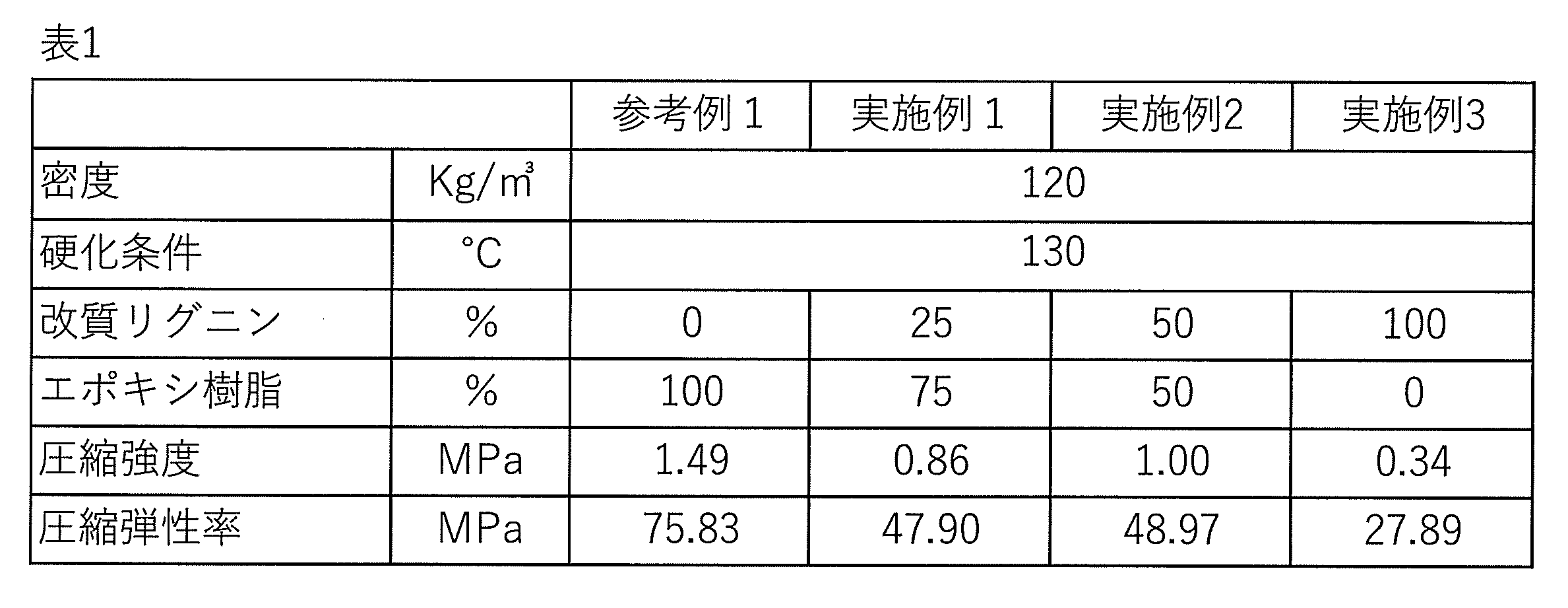
フェノール樹脂に発泡剤を混合攪拌し、成形型に充填し、80~130℃で30分硬化させ、密度120Kg/m3(およそ10倍発泡相当)の発泡体を作製した。上述の方法により圧縮試験を行った結果を表1に示す。
改質リグニンとフェノール樹脂を25:75の質量割合で混合、攪拌した後、更に発泡剤を混合攪拌し、成形型に充填し、80~130℃で30分硬化させ、密度120Kg/m3(およそ10倍発泡相当)の発泡体を作製した。上述の方法により圧縮試験を行った結果を表2に示す。
改質リグニンとフェノール樹脂を50:50の質量割合としたこと以外は実施例4と同様にして発泡体を作製した。上述の方法により圧縮試験を行った結果を表2に示す。
改質リグニンとフェノール樹脂を75:25の質量割合としたこと以外は実施例4と同様にして発泡体を作製した。上述の方法により圧縮試験を行った結果を表2に示す。
なお、表2中には、参考までに実施例3の情報を示す。

フェノール樹脂に発泡剤を混合攪拌し、成形型に充填し、80~180℃で60分硬化させ、密度120Kg/m3(およそ10倍発泡相当)の発泡体を作製した。上述の方法により圧縮試験を行った結果を表3に示す。
改質リグニンとフェノール樹脂を25:75の質量割合で混合、攪拌した後、更に発泡剤を混合攪拌し、成形型に充填し、80~180℃で60分硬化させ、密度120Kg/m3(およそ10倍発泡相当)の発泡体を作製した。上述の方法により圧縮試験を行った結果を表3に示す。
改質リグニンとフェノール樹脂を50:50の質量割合としたこと以外は実施例7と同様にして発泡体を作製した。上述の方法により圧縮試験を行った結果を表3に示す。
改質リグニンとフェノール樹脂を75:25の質量割合としたこと以外は実施例7と同様にして発泡体を作製した。上述の方法により圧縮試験を行った結果を表3に示す。
改質リグニンに発泡剤を混合攪拌し、成形型に充填し、80~180℃で60分硬化させ、密度120Kg/m3(およそ10倍発泡相当)の発泡体を作製した。上述の方法により圧縮試験を行った結果を表3に示す。
改質リグニンとエポキシ樹脂とフェノール樹脂とを33.3:33.3:33.3の質量割合で混合、攪拌した後、更に発泡剤を混合攪拌し、成形型に充填し、80~130℃で30分硬化させ、密度120Kg/m3(およそ10倍発泡相当)の発泡体を作製した。上述の方法により圧縮試験を行った結果を表4に示す。
改質リグニンとエポキシ樹脂とフェノール樹脂とを12.5:75:12.5の質量割合としたこと以外は実施例11と同様にして発泡体を作製した。上述の方法により圧縮試験を行った結果を表4に示す。
ポリエチレングリコールにより化学修飾された改質リグニンとカーボンブラックを95:5の質量割合で混合、攪拌した後、更に発泡剤を混合攪拌し、成形型に充填し、80~130℃で30分硬化させ、密度240Kg/m3(およそ5倍発泡相当)の発泡体を作製した。
カーボンブラックを8質量%、10質量%となるように配合比を変更した以外は実施例13に示した方法と同様の方法により、実施例14~15の発泡体を作製した。
フェノール樹脂とカーボンブラックを95:5の質量割合で混合、攪拌した後、更に発泡剤を混合攪拌し、成形型に充填し、80~130℃で30分硬化させ、密度240Kg/m3(およそ5倍発泡相当)の発泡体を作製した。
カーボンブラックを7.5質量%、8.5質量%、10質量%となるように配合比を変更した以外は参考例4に示した方法と同様の方法により、参考例5~7の発泡体を作製した。
発泡剤の添加量を変更し、発泡倍率をおよそ10倍とした以外は、実施例13と同様の方法により、発泡体を作製した。
カーボンブラックを10質量%、15質量%、20質量%となるように配合比を変更した以外は実施例16に示した方法と同様の方法により、実施例17~19の発泡体を作製した。
発泡剤の添加量を変更し、発泡倍率をおよそ10倍とした以外は、参考例4と同様の方法により、発泡体を作製した。
カーボンブラックを7.5質量%、10質量%、15質量%、20質量%、25質量%となるように配合比を変更した以外は参考例8に示した方法と同様の方法により、参考例9~13の発泡体を作製した。
1:第1繊維強化樹脂層
2:発泡体層
3:第2繊維強化樹脂層
11:導電性材料の含有量0質量%の発泡体層
12:導電性材料の含有量1質量%の発泡体層
13:導電性材料の含有量5質量%の発泡体層
14:導電性材料の含有量10質量%の発泡体層
15:導電性材料の含有量20質量%の発泡体層
Claims (25)
- ポリエチレングリコールにより化学修飾された改質リグニンを含む、発泡体。
- 樹脂を更に含む、請求項1に記載の発泡体。
- 前記樹脂が、フェノール樹脂、エポキシ樹脂、シアネートエステル樹脂、及びウレタン樹脂からなる群から選ばれる少なくとも1種を含む、請求項2に記載の発泡体。
- 前記樹脂が、フェノール樹脂を含む、請求項2に記載の発泡体。
- 前記樹脂が、エポキシ樹脂を含む、請求項2に記載の発泡体。
- 前記改質リグニン、エポキシ樹脂及び硬化剤を含む硬化性樹脂組成物の硬化物を含む、請求項5に記載の発泡体。
- 前記改質リグニンの含有量が、発泡体全量に対して、10~60質量%である、請求項1に記載の発泡体。
- JIS K 7220:2006の圧縮試験による圧縮弾性率が、20~80MPaである、請求項1に記載の発泡体。
- JIS K 7220:2006の圧縮試験における圧縮強度が、0.4~2.0MPaである、請求項1に記載の発泡体。
- 樹脂、及び繊維を含有する第1繊維強化樹脂層と、
請求項1~9のいずれか一項に記載の発泡体を含む発泡体層と、
樹脂、及び繊維を含有する第2繊維強化樹脂層と、
をこの順で有する、積層構造体。 - 前記第1繊維強化樹脂層及び前記第2繊維強化樹脂層が、ポリエチレングリコールにより化学修飾された改質リグニンを含む、請求項10に記載の積層構造体。
- 改質リグニン、及び導電性材料を含む、発泡体。
- 前記改質リグニンが、ポリエチレングリコールにより化学修飾された改質リグニンを含む、請求項12に記載の発泡体。
- 前記改質リグニンの含有量が、発泡体全量に対して、10~99質量%である、請求項12に記載の発泡体。
- 前記導電性材料が、導電性カーボンである、請求項12に記載の発泡体。
- 前記導電性材料が、カーボンブラックである、請求項12に記載の発泡体。
- 前記導電性材料の含有量が、発泡体全量に対して、1~30質量%である、請求項12に記載の発泡体。
- 前記発泡体の発泡倍率が、2~20倍である、請求項12に記載の発泡体。
- 樹脂を更に含む、請求項12に記載の発泡体。
- 前記樹脂が、フェノール樹脂を含む、請求項19に記載の発泡体。
- 前記樹脂の含有量が、発泡体全量に対して、1~89質量%である、請求項19に記載の発泡体。
- 生分解性である、請求項1~9、及び12~21のいずれか一項に記載の発泡体。
- 請求項12~21のいずれか一項に記載の発泡体からなる層が複数積層され、
複数の前記層における、前記導電性材料の含有量が、互いに異なる、積層構造体。 - 最表層側からn番目の前記層を第n層とし、前記第n層における前記導電性材料の含有量をAnとし、且つ、n-1番目の前記層を第n-1層とし、前記第n-1層における前記導電性材料の含有量をAn-1としたとき、
任意のnにおいて以下の関係式(1)を満たす、請求項23に記載の積層構造体。
An-1<An (1)
(式中、nは、2以上、且つ、前記発泡体からなる層の積層数以下の整数である。) - 電波吸収用である、請求項23に記載の積層構造体。
Priority Applications (2)
| Application Number | Priority Date | Filing Date | Title |
|---|---|---|---|
| JP2024520498A JPWO2023219158A1 (ja) | 2022-05-12 | 2023-05-12 | |
| EP23803632.1A EP4524186A4 (en) | 2022-05-12 | 2023-05-12 | EXPANDED BODY AND LAYER STRUCTURE |
Applications Claiming Priority (2)
| Application Number | Priority Date | Filing Date | Title |
|---|---|---|---|
| JP2022078699 | 2022-05-12 | ||
| JP2022-078699 | 2022-05-12 |
Publications (1)
| Publication Number | Publication Date |
|---|---|
| WO2023219158A1 true WO2023219158A1 (ja) | 2023-11-16 |
Family
ID=88730374
Family Applications (1)
| Application Number | Title | Priority Date | Filing Date |
|---|---|---|---|
| PCT/JP2023/017881 Ceased WO2023219158A1 (ja) | 2022-05-12 | 2023-05-12 | 発泡体、及び積層構造体 |
Country Status (3)
| Country | Link |
|---|---|
| EP (1) | EP4524186A4 (ja) |
| JP (1) | JPWO2023219158A1 (ja) |
| WO (1) | WO2023219158A1 (ja) |
Cited By (2)
| Publication number | Priority date | Publication date | Assignee | Title |
|---|---|---|---|---|
| WO2024225405A1 (ja) * | 2023-04-28 | 2024-10-31 | 旭化成建材株式会社 | フェノール樹脂発泡体及びその製造方法 |
| CN119554921A (zh) * | 2024-12-02 | 2025-03-04 | 中国航发北京航空材料研究院 | 一种承力防弹一体化复合板 |
Citations (9)
| Publication number | Priority date | Publication date | Assignee | Title |
|---|---|---|---|---|
| JPH08225628A (ja) * | 1994-12-06 | 1996-09-03 | Elastogran Mas Gmbh & Co | リグニン−ポリエーテル−ポリオールを基礎とする、圧力下に在り、発泡剤を含有するイソシアナート半プリポリマー混合物、これをポリウレタン発泡体製造のために使用する方法およびこの発泡体の製造方法 |
| JP2003277615A (ja) * | 2002-03-25 | 2003-10-02 | Toshiba Corp | 樹脂組成物 |
| JP2006156750A (ja) * | 2004-11-30 | 2006-06-15 | Toray Ind Inc | 電波吸収ボード |
| JP2010254952A (ja) * | 2009-03-31 | 2010-11-11 | Hishie Kagaku Kk | 発泡用樹脂組成物及びリグニン含有高分子発泡体 |
| JP2011219734A (ja) * | 2010-02-10 | 2011-11-04 | Hitachi Chem Co Ltd | 木質系発泡体 |
| JP2017197517A (ja) | 2016-04-21 | 2017-11-02 | 国立研究開発法人森林研究・整備機構 | グリコールリグニンの製造方法及びそのシステム |
| JP2019108490A (ja) | 2017-12-19 | 2019-07-04 | 国立研究開発法人産業技術総合研究所 | 加熱硬化用組成物および熱硬化性プラスチックの製造方法 |
| JP2020203968A (ja) * | 2019-06-14 | 2020-12-24 | 国立研究開発法人産業技術総合研究所 | リグニンを含む熱硬化性樹脂組成物粉体 |
| JP2021123717A (ja) * | 2020-01-31 | 2021-08-30 | 国立研究開発法人森林研究・整備機構 | 樹脂組成物 |
Family Cites Families (2)
| Publication number | Priority date | Publication date | Assignee | Title |
|---|---|---|---|---|
| CN105968616A (zh) * | 2016-03-23 | 2016-09-28 | 马鞍山金晟工业设计有限公司 | 一种超耐温差不易脆聚氯乙烯发泡管 |
| CN107227000A (zh) * | 2017-07-26 | 2017-10-03 | 合肥梵腾环保科技有限公司 | 一种防火吸声驱虫环保发泡材料及其制备方法 |
-
2023
- 2023-05-12 EP EP23803632.1A patent/EP4524186A4/en active Pending
- 2023-05-12 JP JP2024520498A patent/JPWO2023219158A1/ja active Pending
- 2023-05-12 WO PCT/JP2023/017881 patent/WO2023219158A1/ja not_active Ceased
Patent Citations (9)
| Publication number | Priority date | Publication date | Assignee | Title |
|---|---|---|---|---|
| JPH08225628A (ja) * | 1994-12-06 | 1996-09-03 | Elastogran Mas Gmbh & Co | リグニン−ポリエーテル−ポリオールを基礎とする、圧力下に在り、発泡剤を含有するイソシアナート半プリポリマー混合物、これをポリウレタン発泡体製造のために使用する方法およびこの発泡体の製造方法 |
| JP2003277615A (ja) * | 2002-03-25 | 2003-10-02 | Toshiba Corp | 樹脂組成物 |
| JP2006156750A (ja) * | 2004-11-30 | 2006-06-15 | Toray Ind Inc | 電波吸収ボード |
| JP2010254952A (ja) * | 2009-03-31 | 2010-11-11 | Hishie Kagaku Kk | 発泡用樹脂組成物及びリグニン含有高分子発泡体 |
| JP2011219734A (ja) * | 2010-02-10 | 2011-11-04 | Hitachi Chem Co Ltd | 木質系発泡体 |
| JP2017197517A (ja) | 2016-04-21 | 2017-11-02 | 国立研究開発法人森林研究・整備機構 | グリコールリグニンの製造方法及びそのシステム |
| JP2019108490A (ja) | 2017-12-19 | 2019-07-04 | 国立研究開発法人産業技術総合研究所 | 加熱硬化用組成物および熱硬化性プラスチックの製造方法 |
| JP2020203968A (ja) * | 2019-06-14 | 2020-12-24 | 国立研究開発法人産業技術総合研究所 | リグニンを含む熱硬化性樹脂組成物粉体 |
| JP2021123717A (ja) * | 2020-01-31 | 2021-08-30 | 国立研究開発法人森林研究・整備機構 | 樹脂組成物 |
Non-Patent Citations (1)
| Title |
|---|
| See also references of EP4524186A4 |
Cited By (4)
| Publication number | Priority date | Publication date | Assignee | Title |
|---|---|---|---|---|
| WO2024225405A1 (ja) * | 2023-04-28 | 2024-10-31 | 旭化成建材株式会社 | フェノール樹脂発泡体及びその製造方法 |
| JPWO2024225405A1 (ja) * | 2023-04-28 | 2024-10-31 | ||
| JP7896178B2 (ja) | 2023-04-28 | 2026-07-28 | 旭化成建材株式会社 | フェノール樹脂発泡体及びその製造方法 |
| CN119554921A (zh) * | 2024-12-02 | 2025-03-04 | 中国航发北京航空材料研究院 | 一种承力防弹一体化复合板 |
Also Published As
| Publication number | Publication date |
|---|---|
| JPWO2023219158A1 (ja) | 2023-11-16 |
| EP4524186A1 (en) | 2025-03-19 |
| EP4524186A4 (en) | 2026-07-29 |
Similar Documents
| Publication | Publication Date | Title |
|---|---|---|
| Amran et al. | Polyols and rigid polyurethane foams derived from liquefied lignocellulosic and cellulosic biomass | |
| US6596373B1 (en) | Epoxy resin composition for fiber-reinforced composite material prepreg, and fiber-reinforced composite material | |
| EP4524186A1 (en) | Foamed body and layered structure | |
| JP5704198B2 (ja) | セルロースナノファイバー含有エポキシ樹脂組成物の製造方法、強化マトリクス樹脂及び繊維強化樹脂複合体 | |
| JP5543879B2 (ja) | エポキシ樹脂用硬化剤組成物及び一液性エポキシ樹脂組成物 | |
| US9776341B2 (en) | Low density composite materials, their production and use | |
| EP3632952B1 (en) | Epoxy resin composition for fiber-reinforced composite materials, and fiber-reinforced composite material | |
| US6620510B1 (en) | Epoxy resin composition, prepreg, and roll made of resin reinforced with reinforcing fibers | |
| EP3663338A1 (en) | Sheet molding compound, prepreg, and fiber-reinforced composite material | |
| KR20140127867A (ko) | 섬유강화 복합 재료 | |
| JPH1143546A (ja) | クロスプリプレグおよびハニカム構造体 | |
| Kumar et al. | Biomass-derived epoxy resin and its application for high-performance natural fiber composites | |
| JP6514764B2 (ja) | プリプレグおよび繊維強化複合材料 | |
| CN102516530A (zh) | 一种环氧基改质聚苯醚树脂、树脂组合物及其应用 | |
| Teo et al. | Mechanical behavior of palm oil–based composite foam and its sandwich structure with a flax–epoxy composite | |
| Gao et al. | Investigation of novel lightweight phenolic foam‐based composites reinforced with flax fiber mats | |
| CN114641533B (zh) | 环氧树脂混合物、环氧树脂组合物、树脂片、预浸料及碳纤维强化复合材料 | |
| Adebayo et al. | Development and characterization of lignin-furan rigid foams by varying precursors and catalyst concentration | |
| Li et al. | Synthesis of bio-/lignin-based phenolic foams for insulation and floral applications | |
| KR102153308B1 (ko) | 나노셀룰로오스 복합시트 및 이의 제조방법 | |
| JP2020158716A (ja) | 硬化性樹脂組成物、及びそれを用いたトゥプリプレグ | |
| EP3165569B1 (en) | Prepreg and fibre-reinforced composite foam material | |
| Biswal et al. | Epoxy foams | |
| CN116215046B (zh) | 一种耐冲击型及环境适应性纤维增强树脂基复合材料及其预浸料制造方法 | |
| WO2023219157A1 (ja) | 硬化性樹脂組成物、硬化物、プリプレグ、プリプレグの硬化物、積層構造体、硬化性樹脂組成物の製造方法、及び硬化物の製造方法 |
Legal Events
| Date | Code | Title | Description |
|---|---|---|---|
| 121 | Ep: the epo has been informed by wipo that ep was designated in this application |
Ref document number: 23803632 Country of ref document: EP Kind code of ref document: A1 |
|
| WWE | Wipo information: entry into national phase |
Ref document number: 2024520498 Country of ref document: JP |
|
| WWE | Wipo information: entry into national phase |
Ref document number: 2023803632 Country of ref document: EP |
|
| NENP | Non-entry into the national phase |
Ref country code: DE |
|
| ENP | Entry into the national phase |
Ref document number: 2023803632 Country of ref document: EP Effective date: 20241212 |