WO2023224048A1 - ポリテトラフルオロエチレンチューブ及びそれを使用した医療用チューブ - Google Patents
ポリテトラフルオロエチレンチューブ及びそれを使用した医療用チューブ Download PDFInfo
- Publication number
- WO2023224048A1 WO2023224048A1 PCT/JP2023/018302 JP2023018302W WO2023224048A1 WO 2023224048 A1 WO2023224048 A1 WO 2023224048A1 JP 2023018302 W JP2023018302 W JP 2023018302W WO 2023224048 A1 WO2023224048 A1 WO 2023224048A1
- Authority
- WO
- WIPO (PCT)
- Prior art keywords
- tube
- ptfe
- polytetrafluoroethylene
- strain
- stress
- Prior art date
- Legal status (The legal status is an assumption and is not a legal conclusion. Google has not performed a legal analysis and makes no representation as to the accuracy of the status listed.)
- Ceased
Links
Images

Classifications
-
- A—HUMAN NECESSITIES
- A61—MEDICAL OR VETERINARY SCIENCE; HYGIENE
- A61L—METHODS OR APPARATUS FOR STERILISING MATERIALS OR OBJECTS IN GENERAL; DISINFECTION, STERILISATION OR DEODORISATION OF AIR; CHEMICAL ASPECTS OF BANDAGES, DRESSINGS, ABSORBENT PADS OR SURGICAL ARTICLES; MATERIALS FOR BANDAGES, DRESSINGS, ABSORBENT PADS OR SURGICAL ARTICLES
- A61L29/00—Materials for catheters, medical tubing, cannulae, or endoscopes or for coating catheters
- A61L29/04—Macromolecular materials
-
- A—HUMAN NECESSITIES
- A61—MEDICAL OR VETERINARY SCIENCE; HYGIENE
- A61L—METHODS OR APPARATUS FOR STERILISING MATERIALS OR OBJECTS IN GENERAL; DISINFECTION, STERILISATION OR DEODORISATION OF AIR; CHEMICAL ASPECTS OF BANDAGES, DRESSINGS, ABSORBENT PADS OR SURGICAL ARTICLES; MATERIALS FOR BANDAGES, DRESSINGS, ABSORBENT PADS OR SURGICAL ARTICLES
- A61L29/00—Materials for catheters, medical tubing, cannulae, or endoscopes or for coating catheters
- A61L29/14—Materials characterised by their function or physical properties, e.g. lubricating compositions
-
- A—HUMAN NECESSITIES
- A61—MEDICAL OR VETERINARY SCIENCE; HYGIENE
- A61M—DEVICES FOR INTRODUCING MEDIA INTO, OR ONTO, THE BODY; DEVICES FOR TRANSDUCING BODY MEDIA OR FOR TAKING MEDIA FROM THE BODY; DEVICES FOR PRODUCING OR ENDING SLEEP OR STUPOR
- A61M25/00—Catheters; Hollow probes
Definitions
- the present invention relates to a fluororesin tube, and particularly to a thin-walled tube made of polytetrafluoroethylene (hereinafter referred to as "PTFE").
- PTFE polytetrafluoroethylene
- ⁇ Endovascular surgery in which a catheter is inserted into a blood vessel to remove and treat the lesion inside the blood vessel, is becoming mainstream because it places less burden on the patient.
- Catheters used for such purposes are inserted percutaneously into the body, and the tip of the tube must reach the lesion site via a blood vessel. Therefore, the catheter is required to have the ability to move straight through the blood vessel, and the ability to transmit operations to the operator performing the treatment.
- catheters are constructed by laminating layers with different properties.
- the interior of the catheter must accommodate operations such as insertion of treatment tools and injection of medical solutions, so the inner surface must have low friction and high strength, and the inner diameter must be as large as possible.
- the outer diameter of the catheter is required to be small in consideration of the burden on the patient. Therefore, it is desirable that each layer constituting the catheter be as thin as possible.
- PTFE tubes are suitably used in medical applications due to their excellent properties such as chemical resistance, non-stick properties, and low friction properties.
- One method for manufacturing a catheter tube is to coat a core wire with PTFE, form an outer resin layer thereon, and then pull out the core wire to obtain a catheter tube.
- a core wire is inserted into a PTFE tube, and in this state, the PTFE tube is stretched to reduce its diameter, and the PTFE tube is brought into contact with the surface of the core wire.
- the PTFE tube used must have both strength to withstand stretching and extensibility to enable stretching.
- the PTFE layer on the core wire has a uniform thickness, and the stretched PTFE tube is required to have high dimensional accuracy and uniform extensibility. be done.
- PTFE has a very high melt viscosity
- long PTFE molded products are generally formed by paste extrusion rather than melt extrusion.
- tubes formed by the dipping method may have defects such as pinholes, and have other problems such as poor strength.
- Patent Document 2 discloses a method of paste-extruding a PTFE resin onto a metal core wire to obtain a thin-walled tube.
- Patent Document 3 discloses a method of thinning a PTFE tube by forming the PTFE tube by paste extrusion and then stretching the PTFE tube in the longitudinal direction.
- stretching a PTFE tube although it is possible to reduce the thickness of the tube and ensure the strength of the tube, there is a problem in that the extensibility and flexibility of the tube are lost.
- the present invention has been developed to have appropriate extensibility and sufficient strength, as well as uniformity during stretching, which is necessary when using PTFE tubes to cover core wires, etc.
- the present invention provides a thin-walled PTFE tube with good quality, and provides a medical tube with excellent flexibility and dimensional accuracy.
- the stress-strain curve obtained by a tensile test conducted in an atmosphere of 20% strain tensile stress ⁇ 20 (N/mm 2 ) of the polytetrafluoroethylene tube and 50% strain tensile stress ⁇ 50 (N/mm 2 ) satisfies 2.0 ⁇ 0.1 ⁇ 20 +0.3 ⁇ 50 ⁇ 5.5 (Formula (1)).
- the tensile strain at break is 200% or more in a tensile test conducted in an atmosphere of 200°C, and the 20% strain tensile stress ⁇ 20 is 4 in a tensile test conducted in a 200°C atmosphere. 0 (N/mm 2 ) or more.
- the 20% strain tensile stress ⁇ 20 (N/mm 2 ) of the polytetrafluoroethylene tube and the 50% strain tensile stress ⁇ 50 (N/mm 2 ) of the polytetrafluoroethylene tube are 2. .0 ⁇ 0.1 ⁇ 20 +0.3 ⁇ 50 ⁇ 5.5 (Formula (1)) is a polytetrafluoroethylene tube.
- Another example is a medical tube using a polytetrafluoroethylene tube, wherein the polytetrafluoroethylene tube has a wall thickness of about 0.04 mm or less, and the polytetrafluoroethylene tube has a wall thickness of about 0.04 mm or less.
- the wetting tension of either or both of the outer surface and inner surface is 46 mN/m or more, and in the stress-strain curve obtained by a tensile test conducted in an atmosphere of 200 ° C., the 20% strain tensile stress of the polytetrafluoroethylene tube ⁇ 20 (N/mm 2 ) and the 50% strain tensile stress ⁇ 50 (N/mm 2 ) of the polytetrafluoroethylene tube satisfy the above formula (1).
- a medical tube using a polytetrafluoroethylene tube wherein the polytetrafluoroethylene tube has a wall thickness of about 0.04 mm or less, and an inner diameter of about 3.0 mm. 0 mm or less, and in the stress-strain curve obtained by a tensile test conducted in an atmosphere at 200°C, the 20% strain tensile stress ⁇ 20 (N/mm 2 ) of the polytetrafluoroethylene tube and the polytetrafluoroethylene tube.
- the 50% strain tensile stress ⁇ 50 (N/mm 2 ) satisfies the above formula (1).
- another example is a medical tube including a polytetrafluoroethylene liner obtained by processing a polytetrafluoroethylene tube, wherein the polytetrafluoroethylene liner has a wall thickness of about 0.04 mm or less. , the inner diameter of the polytetrafluoroethylene liner is about 3.0 mm or less, and the polytetrafluoroethylene liner has a stress-strain curve obtained by a tensile test conducted in an atmosphere of 200°C.
- the 20% strain tensile stress ⁇ ' 20 (N/mm 2 ) of the ethylene liner and the 50% strain tensile stress ⁇ ' 50 (N/mm 2 ) of the polytetrafluoroethylene liner are 2.4 ⁇ 0.1 ⁇ ' 20 +0.3 ⁇ ' 50 ⁇ 6.6 (formula (2)) is satisfied.
- the PTFE tube of the present invention has strength and appropriate extensibility, and also has good uniformity during stretching, so it can be suitably used in applications where the PTFE tube is stretched.
- the PTFE tube coated on the core wire is uniform, has small dimensional variations, and has excellent flexibility and dimensional accuracy.
- the PTFE tube of the present invention can be used in products requiring high dimensional accuracy, and is particularly suitable as a liner for medical tubes.
- FIG. 1 is a schematic diagram of a cross section of a PTFE tube of the present invention, explaining the dimensions of the tube.
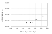
- FIG. 2 is a diagram showing the relationship between the value of the middle side of equation (1) and the variation in outer diameter (coefficient of variation CV) regarding the PTFE tube of the present invention.
- the wall thickness of the PTFE tube is about 0.04 mm or less. Specifically, it is about 0.005 mm to about 0.04 mm, preferably about 0.01 mm to about 0.04 mm, and more preferably about 0.01 mm to about 0.03 mm.
- the thin wall thickness can contribute to reducing the diameter of the catheter without interfering with the function of the catheter. It is preferable that the wall thickness is at least sufficient to ensure airtightness inside the tube.
- the wall thickness of the PTFE tube can be confirmed by measuring a cross section cut perpendicularly to the longitudinal axis of the PTFE tube using a microscope or the like.
- the inner diameter of the PTFE tube is about 3.0 mm or less. Specifically, it is preferably about 0.20 mm to about 3.0 mm, more preferably about 0.25 mm to about 2.0 mm.
- FIG. 1 is a schematic diagram of a cross section 1 of a PTFE tube, and is a diagram illustrating the dimensions of the tube.
- the inner diameter of the tube means the diameter inside the cross section of the tube.
- the inner diameter is the diameter of the inner circle, and is the straight-line distance between points A and B on the inner circle on a straight line passing through the center C of the inner circle.
- the inner diameter of the PTFE tube is determined by measuring the inner diameter at two to four locations (two locations with a straight line angle changed by about 90°) to four locations (four locations with a straight line angle changed by about 45°). Adopted as the inner diameter.
- the wall thickness of the PTFE tube is the distance between point A on the inner circle and point A' on the outer circle on a straight line passing through the center C of the circle, and the distance between point A' on the inner circle and point A' on the outer circle. It is also the distance between and point B' on the outer circle.
- the wall thickness is measured equally at about 4 to 8 locations, and the average value is used as the PTFE tube wall thickness.
- the tensile stress (20% strain tensile stress) when the elongation rate of the polytetrafluoroethylene tube is 20% is ⁇ 20 (N/mm 2 )
- the tensile stress (50% strain tensile stress) when the elongation rate of the polytetrafluoroethylene tube is 50% is ⁇ 50 (N/mm 2 )
- the PTFE tube of the present invention has a wall thickness of ( 0.04 mm or less)
- Equation (1) is the result of data analysis 2.0 ⁇ 0.1 ⁇ 20 +0.3 ⁇ 50 ⁇ 5.5 Formula (1) This has a high correlation with the uniformity of the PTFE tube during stretching.
- the value on the right side of equation (1) is preferably 5.5, more preferably 5.0. If the value on the left side of equation (1) is too small, sufficient strength may not be obtained when stretching the PTFE tube.
- the value on the left side of equation (1) is preferably 2.0, more preferably 3.0. Further, when the PTFE tube of the present invention has an inner diameter of about 3.0 mm or less, the effect tends to be more easily improved when formula (1) is satisfied.
- the values on the right and left sides of equation (1) of the PTFE liner obtained by processing the PTFE tube tend to increase by about 20%. There is. Therefore, the value obtained by subtracting about 20% from the above-mentioned value obtained for the PTFE liner can be treated as the value for the PTFE tube of the present invention.
- the polytetrafluoroethylene tube of the present invention preferably has a tensile strain at break of 200% or more in a tensile test conducted in an atmosphere at 200°C. Further, it is preferable that the 20% strain tensile stress ⁇ 20 of the polytetrafluoroethylene tube in a tensile test conducted in an atmosphere at 200° C. is 4.0 (N/mm 2 ) or more. Further, the 20% strain tensile stress ⁇ 20 of the polytetrafluoroethylene tube is preferably smaller than 11.0 (N/mm 2 ).
- the polytetrafluoroethylene tube of the present invention has a 50% strain tensile stress ⁇ 50 of 6.0 (N/mm 2 ) or more in a tensile test conducted in an atmosphere at 200°C. is preferred. Further, the 50% strain tensile stress ⁇ 50 of the polytetrafluoroethylene tube is preferably smaller than 14.0 (N/mm 2 ).
- a medical tube using the PTFE tube of the present invention which has strength and appropriate extensibility, can have good flexibility.
- the wetting tension of one or both of the outer and inner surfaces of the tube is 46 mN/m or more, and more preferably 60 mN/m or more.
- the wetting tension of the PTFE tube surface can be adjusted by etching (physically or chemically modifying) the surface. Specifically, etching using plasma, corona discharge, ion beam, etc., etching using a mixture of metallic sodium, ammonia, or naphthalene, etc. can be performed. For example, in etching using a solution of naphthalene + sodium metal + diglyme, it is possible to set the wetting tension on the tube surface to 70 mN/m or more.
- the PTFE tube of the present invention has a wet tension of 46 mN/m or more on the outer surface of the tube, and especially when used as a liner for a medical tube, the strength of the inner layer (PTFE layer) against the load applied to the inner surface of the medical tube. Easy to maintain.
- PTFE powder used for tube molding There are two types of PTFE powder used for tube molding: fine powder and molding powder.
- the fine powder used in the embodiment of the present invention is preferably a fine powder that has the property of deforming with fibrillation when shear stress is applied.
- the polytetrafluoroethylene resin used in the embodiments of the present invention may be a homopolymer of tetrafluoroethylene (hereinafter referred to as "TFE") or modified PTFE. Modified PTFE is obtained by polymerizing TFE and a small amount of a monomer other than TFE.
- TFE chlorotrifluoroethylene
- HFP hexafluoropropylene
- PAVE perfluoroalkyl vinyl ether
- modified PTFE is used to improve properties such as heat resistance, abrasion resistance, and bending resistance of molded articles.
- the polytetrafluoroethylene resin used in the embodiment of the present invention may be a single type of PTFE listed above or a blend of multiple types of PTFE.
- the polytetrafluoroethylene tube of the present invention can contain polymers other than the above-mentioned polytetrafluoroethylene resin, as long as the tube does not impair its function.
- PTFE fine powder is generally one in which primary particles with an average particle size of 0.2 to 0.5 ⁇ m aggregate to form secondary particles with an average particle size of 400 to 700 ⁇ m. Even at room temperature, it has the property of being easily fibrillated by vibration, etc., and is likely to form lumps.
- Paste extrusion molding takes advantage of this property. In general, paste extrusion molding involves mixing PTFE and an organic solvent called an auxiliary agent (lubricant) and compressing the mixture to create a preform, then putting the preform into an extruder and applying pressure to create a film. This is a method of extruding it into shapes such as tubes, linear coatings, etc.
- PTFE tube of the present invention since uniformity of the extruded PTFE tube is important, it is preferable to create the preform so that the internal structure of the PTFE preform is uniform.
- PTFE fine powder mixed with an auxiliary agent before creating a preform is handled in such a way that it does not form lumps, and the formed lumps are handled before being put into a compression mold for the preform. Preferably, it is removed with a sieve.
- the auxiliary agent is added to the PTFE fine powder to make it into a paste, which allows it to be molded using an extruder.
- the auxiliary agent used in the embodiment of the present invention is preferably an organic solvent with high lubricity. After adding an auxiliary agent to the PTFE fine powder, it is molded into a tube through a mold using an extruder, but if the auxiliary agent evaporates during molding, stable molding becomes difficult, which is not preferable.
- the auxiliary agent used in the embodiment of the present invention preferably has an initial boiling point (IBP) of 150° C. or higher. After forming the PTFE fine powder and the auxiliary agent into a tube shape, the auxiliary agent is volatilized and removed before firing the tube.
- IBP initial boiling point
- the IBP of the auxiliary agent is preferably 250° C. or lower so that the auxiliary agent can be removed reliably.
- Petroleum-based solvents are often used as organic solvents that have high lubricity and an IBP of 150°C to 250°C.
- the auxiliary agent used in the embodiment of the present invention has an interfacial tension that is 3 mN/m or more higher than the interfacial tension of PTFE, which is 18.5 mN/m. It is thought that the high interfacial tension of the auxiliary agent prevents the auxiliary agent from moving between the PTFE particles more than necessary and makes it easier for the auxiliary agent to remain on the particle surface.
- PTFE paste extrusion molding PTFE particles slide against each other in a mold during extrusion, and the particle surfaces become fibrillated. The intertwining of the fibrils makes it difficult to flow and increases the extrusion pressure.
- the auxiliary agent present around the PTFE particles increases the lubricity between the PTFE particles and between the PTFE particles and the inner wall of the mold, moderately suppresses entanglement between the PTFE particles, and prevents an excessive increase in extrusion pressure.
- the flow path inside the mold is extremely narrow, and the resin flows under conditions of high reduction ratio (hereinafter referred to as "RR"). Therefore, the shear force between the inner wall of the mold and the PTFE particles and between the PTFE particles becomes large.
- the auxiliary agent that remains between the PTFE particles is expected to have the effect of reducing the shear force between the PTFE particles and between the PTFE particles and the inner wall of the mold, and suppressing excessively rapid fibrillation of the PTFE.
- the tube according to the embodiment of the present invention may include a filler or other resin in the polytetrafluoroethylene resin.
- fillers include carbon, metal oxides such as alumina, resin fillers made of fired PTFE, fluororesins other than PTFE, and other resins.
- one or more types can be used in combination with PTFE. It is also possible to configure the PTFE tube with a plurality of layers, and arrange a layer containing a filler or other resin in only one of the layers.
- PTFE fine powder and auxiliary agent are mixed in a tumbler or the like. If a filler or the like is to be added to PTFE, it is best to add it in this step.
- PTFE fine powder is used after removing lumps with a sieve.
- the mixture of PTFE and auxiliary agent is passed through a sieve to remove lumps and then compressed and pressure molded to form a preform. It is desirable that the preform be compressed uniformly to the inside thereof.
- preforms of different sizes can be combined to create a preform composed of a plurality of layers.
- the prepared preform is placed in an extruder and passed through a mold to form a tube.
- the exit temperature of the mold of the extruder is preferably 80°C or more and 150°C or less, more preferably 90°C or more and 120°C or less.
- the cooling rate of the tube extruded from the mold can also affect the 20% strain tensile stress ⁇ 20 and 50% strain tensile stress ⁇ 50 values of the polytetrafluoroethylene tube.
- the temperature of the tube-shaped PTFE around the mold exit can be adjusted.
- the appropriate temperature is considered to be 60°C to 120°C. It is preferable to adjust the extrusion speed and extrusion temperature of the preform to be constant, and to perform molding so that the extrusion pressure is constant. Tube extrusion is carried out in a constant stable state, and the balance between tube delivery and take-up (winding) is adjusted to ensure that no load is applied to the formed tube during the tube extrusion process, drying process, and tube firing process. It is best to handle it so that it does not get damaged.
- Test temperature 200°C ⁇ 3°C Initial chuck distance 50mm Test speed 50mm/min A tube cut to a length suitable for measurement was used as a measurement sample, and measurement was continued until the tube broke to obtain data. The number of test samples was set to 5 or more as much as possible, and the arithmetic mean value of these measured values was used for each stress value.
- the stress when the tube set in the chuck of the testing machine is stretched 20% in the longitudinal direction (extended 10 mm) is defined as 20% strain tensile stress ⁇ 20 and ⁇ ' 20 , and when the tube is stretched 50% in the longitudinal direction (extended 25 mm). 50% strain tensile stress ⁇ 50 and ⁇ ′ 50 .
- a core wire laminated with a PTFE tube (hereinafter referred to as a coated core wire) was cooled and its dimensions were measured. Since a core wire with a constant outer diameter is used, it is possible to calculate the wall thickness of the coated PTFE tube from the outer diameter of the coated core wire and the outer diameter of the core wire. Here, variations in the outer diameter of the coated core wire were treated as variations in the extensibility of the coated PTFE tube and evaluated.
- the dimensions of the coated core wire were measured excluding several tens of mm at both ends.
- the outer diameter was measured at six or more locations as uniformly as possible over the entire length of one coated core wire. Measurements are carried out evenly in the radial direction (cross-sectional direction) at about 2 points (2 points where the measurement angle changes by 90°) to 4 points (4 points where the measurement angle changes by 45°) per measurement point. The arithmetic mean of the measured values was taken as the outer diameter D 0 of that measurement point.
- the coefficient of variation CV D of the outer diameter within one sample is the outer diameter deviation (outer diameter D 0 of the measurement point - outer diameter average value D) and the outer diameter dispersion (the root mean square of the outer diameter deviation).
- the standard deviation of the outer diameter was calculated, and the standard deviation of the outer diameter was divided by the outer diameter average value D. The same operation was repeated for the remaining 19 samples.
- the arithmetic mean value of the calculated outer diameter variation coefficient CV D within each of the 20 samples was defined as the "outer diameter variation coefficient CV".
- ⁇ Wet tension test> Wetting tension was measured in accordance with ISO 8296. Specifically, a test liquid mixture for measuring wet tension (mixture liquid for wet tension test) was quickly applied to the surface of a PTFE tube using a cotton swab, and the state of the liquid film was judged. If no change is observed in the line drawn with the cotton swab for 2 seconds, the surface tension of the PTFE tube is determined to be greater than or equal to the surface tension of the wetting tension test mixture. On the other hand, if the width of the line drawn with a cotton swab on the wetting tension test mixture shrinks in less than 2 seconds or the liquid film ruptures, the mixture has a lower surface tension than the wetting tension test mixture. Evaluate using.
- Example 1 In a container, 100 parts by mass of PTFE fine powder from which lumps were removed with a sieve and 18 parts by mass of an auxiliary agent were placed and mixed, and after removing lumps with a sieve, the mixture was compressed to create a preform.
- This preform was put into an extrusion molding machine with a cylinder diameter of 20 mm and a mandrel diameter of 10 mm, and extruded at a mold temperature of 100° C. to form a tube shape.
- the area around the mold after the PTFE was discharged from the mold outlet was covered with a heater, and the temperature around the mold outlet was adjusted to 90°C.
- the formed tube was dried and fired by passing through a first drying oven set at 150°C, a second drying oven set at 220°C, and a firing oven set at 430°C.
- the obtained tube had an inner diameter of 0.60 mm and a wall thickness of 0.028 mm.
- Tetra Etch (registered trademark) was applied to the surface of the obtained tube, and etching treatment was performed by washing with alcohol and water to create a PTFE tube according to an embodiment of the present invention.
- the obtained PTFE tube was cut to a length of about 100 mm to prepare a sample for a tensile test. A tensile test was conducted in an atmosphere at 200° C. according to the method described above.
- Example 2 A preformed body prepared in the same manner as in Example 1 was placed in an extrusion molding machine with a cylinder diameter of 30 mm and a mandrel diameter of 10 mm, and extruded at a mold temperature of 90° C. to form a tube shape. After the PTFE was discharged from the mold outlet, the area around the mold was covered with a heater, and the temperature around the mold outlet was adjusted to 80°C.
- the formed tube was dried and fired by passing through a drying furnace and a firing furnace.
- the obtained tube had an inner diameter of 1.72 mm and a wall thickness of 0.038 mm.
- Tetra Etch (registered trademark) was applied to the surface of the obtained tube, and etching treatment was performed by washing with alcohol and water to create a PTFE tube according to an embodiment of the present invention.
- the obtained PTFE tube was cut to a length of about 100 mm to prepare a sample for a tensile test. A tensile test was conducted in an atmosphere at 200° C. according to the method described above.
- the obtained PTFE tube was cut into pieces of about 1000 mm and used as samples for evaluation.
- Example 3 A preformed body prepared in the same manner as in Example 1 was placed in an extrusion molding machine, and extruded at a mold temperature of 100°C to form a tube shape. After the PTFE was discharged from the mold outlet, the area around the mold was covered with a heater, and the temperature around the mold outlet was adjusted to 80°C. As in Example 1, the formed tube was dried and fired by passing through a drying furnace and a firing furnace. The obtained tube had an inner diameter of 0.475 mm and a wall thickness of 0.028 mm.
- the surface of the obtained tube was subjected to plasma treatment by passing through a plasma generated using an applied voltage of 10 kV, a frequency of 18 kHz, and an excited Ar gas at a speed of 6.0 m/min. Created a tube.
- the obtained PTFE tube was cut to a length of about 100 mm to prepare a sample for a tensile test. A tensile test was conducted in an atmosphere at 200° C. according to the method described above.
- the obtained PTFE tube was cut into pieces of about 1000 mm and used as samples for evaluation.
- a core wire with an outer diameter of 0.41 mm and a length of about 980 mm was prepared, and a heating stretching test was conducted according to the method described above.
- Example 4 A preformed body prepared in the same manner as in Example 1 was placed in an extrusion molding machine, and extruded at a mold temperature of 100°C to form a tube shape. After the PTFE was discharged from the mold outlet, the area around the mold was covered with a heater, and the temperature around the mold outlet was adjusted to 100°C. As in Example 1, the formed tube was dried and fired by passing through a drying furnace and a firing furnace. The obtained tube had an inner diameter of 0.49 mm and a wall thickness of 0.038 mm.
- Tetra Etch (registered trademark) was applied to the surface of the obtained tube, and etching treatment was performed by washing with alcohol and water to create a PTFE tube according to an embodiment of the present invention.
- the obtained PTFE tube was cut to a length of about 100 mm to prepare a sample for a tensile test. A tensile test was conducted in an atmosphere at 200° C. according to the method described above. In addition, the obtained PTFE tube was cut into pieces of about 1000 mm and used as samples for evaluation.
- a core wire with an outer diameter of 0.41 mm and a length of about 980 mm was prepared, and a heating stretching test was conducted according to the method described above. Wetting tension was also measured according to the method described above.
- Example 5 A preformed body prepared in the same manner as in Example 1 was put into an extrusion molding machine, and extruded at a mold temperature of 80° C. to form a tube shape. After the PTFE was discharged from the mold outlet, the area around the mold was covered with a heater, and the temperature around the mold outlet was adjusted to 60°C. As in Example 1, the formed tube was dried and fired by passing through a drying furnace and a firing furnace. The obtained tube had an inner diameter of 0.50 mm and a wall thickness of 0.022 mm.
- the surface of the obtained tube was subjected to plasma treatment by passing it through a plasma generated using an applied voltage of 10 kV, a frequency of 18 kHz, and an excited Ar gas at a speed of 2 m/min to obtain a PTFE tube according to an embodiment of the present invention.
- a plasma generated using an applied voltage of 10 kV, a frequency of 18 kHz, and an excited Ar gas at a speed of 2 m/min to obtain a PTFE tube according to an embodiment of the present invention.
- the obtained PTFE tube was cut into a length of about 100 mm and used as a sample for a tensile test. A tensile test was conducted in an atmosphere at 200° C. according to the method described above.
- the obtained PTFE tube was cut into pieces of about 1000 mm and used as samples for evaluation.
- Example 6 A preformed body prepared in the same manner as in Example 1 was placed in an extrusion molding machine with a cylinder diameter of 44 mm, and extruded at a mold temperature of 100° C. to form a tube shape. After the PTFE was discharged from the mold outlet, the area around the mold was covered with a heater, and the temperature around the mold outlet was adjusted to 80°C. As in Example 1, the formed tube was dried and fired by passing through a drying furnace and a firing furnace.
- the obtained tube had an inner diameter of 2.68 mm and a wall thickness of 0.033 mm.
- Tetra Etch (registered trademark) was applied to the surface of the obtained tube, and etching treatment was performed by washing with alcohol and water to create a PTFE tube according to an embodiment of the present invention.
- the obtained PTFE tube was cut to a length of about 100 mm to prepare a sample for a tensile test. A tensile test was conducted in an atmosphere at 200° C. according to the method described above. In addition, the obtained PTFE tube was cut into pieces of about 1000 mm and used as samples for evaluation.
- a core wire with an outer diameter of 2.42 mm and a length of about 980 mm was prepared, and a heating stretching test was conducted according to the above method. Wetting tension was also measured according to the method described above.
- FIG. 2 is a diagram in which the value of the middle side of equation (1) and the variation in outer diameter (coefficient of variation CV of outer diameter) are plotted for the PTFE tube of the example. From this plot, relational equation (1) It can be confirmed that this has a high correlation with the uniform extensibility when the core wire is covered with a PTFE tube.
- the PTFE tube of the present invention can be suitably used for tube liners, etc., and the multilayer tube using the PTFE tube of the present invention can be particularly suitably used for medical tubes and the like.
Landscapes
- Health & Medical Sciences (AREA)
- Life Sciences & Earth Sciences (AREA)
- Veterinary Medicine (AREA)
- Animal Behavior & Ethology (AREA)
- General Health & Medical Sciences (AREA)
- Public Health (AREA)
- Epidemiology (AREA)
- Biophysics (AREA)
- Pulmonology (AREA)
- Engineering & Computer Science (AREA)
- Anesthesiology (AREA)
- Biomedical Technology (AREA)
- Heart & Thoracic Surgery (AREA)
- Hematology (AREA)
- Materials For Medical Uses (AREA)
Abstract
Description
また、芯線上を薄肉に成形したPTFEチューブで被覆する方法もある。この方法では、芯線をPTFEチューブに挿通し、その状態でPTFEチューブを延伸して縮径させて、芯線の表面にPTFEチューブを接触させる。この方法においては、使用するPTFEチューブの特性として、延伸に耐える強度と延伸を可能にする伸長性の両方が必要となる。また、高い寸法精度が要求されるカテーテル製造工程においては、芯線上のPTFE層は均一な肉厚であることが望ましく、延伸するPTFEチューブには高い寸法精度と均一な伸長性を有することが要求される。
また、ポリテトラフルオロエチレンチューブを使用した医療用チューブであって、前記ポリテトラフルオロエチレンチューブは、肉厚が約0.04mm以下であり、かつ、該ポリテトラフルオロエチレンチューブの内径が約3.0mm以下であり、200℃の雰囲気下で行う引張試験によって得られる応力‐ひずみ曲線において、該ポリテトラフルオロエチレンチューブの20%ひずみ引張応力σ20(N/mm2)と該ポリテトラフルオロエチレンチューブの50%ひずみ引張応力σ50(N/mm2)が、上述の式(1)を満たすものである。
さらに、別の一例では、ポリテトラフルオロエチレンチューブを加工したポリテトラフルオロエチレンライナーを含む医療用チューブであって、該ポリテトラフルオロエチレンライナーの肉厚が約0.04mm以下であるチューブであって、該ポリテトラフルオロエチレンライナーの内径が約3.0mm以下であり、かつ、該ポリテトラフルオロエチレンライナーは、200℃の雰囲気下で行う引張試験によって得られる応力‐ひずみ曲線において、該ポリテトラフルオロエチレンライナーの20%ひずみ引張応力σ’20(N/mm2)と該ポリテトラフルオロエチレンライナーの50%ひずみ引張応力σ’50(N/mm2)が、2.4 ≦ 0.1×σ’20+0.3×σ’50 <6.6(式(2))を満たすものである。
2.0 ≦ 0.1×σ20+0.3×σ50 <5.5 式 (1)
得られたものであり、PTFEチューブの延伸時の均一性との相関が高い。式(1)の右辺の値は、5.5であることが好ましく、5.0であることがより好ましい。式(1)の左辺の値が小さすぎると、PTFEチューブを延伸するときの強度が十分に得られない場合がある。式(1)の左辺の値は、2.0であることが好ましく、3.0 であることがより好ましい。また、本発明のPTFEチューブは、その内径が約3.0mm以下である場合に、式(1)を満たすとより効果が向上しやすい傾向がある。
PTFEチューブの上に外層樹脂層などが形成される場合、PTFEチューブを加工して得られたPTFEライナーの、式(1)の右辺の値と左辺の値は、いずれも2割程度増加する傾向がある。そこで、そのPTFEライナーについて得られた上述の値から2割程度減算した値を、本発明のPTFEチューブの値として扱うことができる。
強度と適度な伸長性を備える本発明のPTFEチューブを使用した医療用チューブは、良好な柔軟性を有するチューブとすることができる。
チューブの成形に使用されるPTFEパウダーには、ファインパウダーとモールディングパウダーの二種類がある。本発明の実施形態で使用するのは、せん断応力を加えるとフィブリル化を伴って変形する性質を持つファインパウダーが好ましい。本発明の実施形態で使用するポリテトラフルオロエチレン樹脂は、テトラフルオロエチレン(以下、「TFE」と言う)のホモポリマーであっても、変性PTFEであっても良い。変性PTFEは、TFEと少量のTFE以外の単量体とを重合させたものである。少量のTFE以外の単量体は、たとえば、クロロトリフルオロエチレン(CTFE)、ヘキサフルオロプロピレン(HFP)、パーフルオロアルキルビニルエーテル(PAVE)などが挙げられる。一般に、変性PTFEは、成形品の耐熱性、耐摩耗性、耐屈曲性などの特性を向上させるために用いられる。本発明の実施形態で使用するポリテトラフルオロエチレン樹脂としては、上記で挙げたPTFE種を単一であっても、複数種のブレンドしたものであってもよい。また、本発明のポリテトラフルオロエチレンチューブは、その機能を損なわない限り少量であれば、上述のポリテトラフルオロエチレン樹脂以外のポリマーを含むことができる。
[予備成形体の成形]
PTFEファインパウダーと助剤とを、タンブラーなどで混合する。PTFEにフィラーなどを添加する場合は、この工程で添加すると良い。PTFEファインパウダーは、篩などで塊を除去して使用する。PTFEと助剤の混合物を篩に通して塊を取り除いた後、圧縮して加圧成形し、予備成形体を作成する。予備成形体は、その内部まで均一に圧縮されていることが望ましい。PTFEチューブを複数の層で構成する場合は、例えば、サイズの異なる予備成形体を組み合わせて、複数の層で構成した予備成形体を作成することができる。
[押出成形]
作成した予備成形体を押出機にセットし、金型を通してチューブ形状に成形する。
押出機の金型の出口温度は、80℃以上150℃以下が好ましく、90℃以上120℃以下がより好ましい。金型の温度が高いと、PTFE粒子表面のフィブリル化が促進され、形成されたフィブリルの絡み合いが強くなる傾向がある。また、金型から押出されたチューブの冷却速度も、ポリテトラフルオロエチレンチューブの20%ひずみ引張応力σ20の値と50%ひずみ引張応力σ50の値に影響を与え得る。例えば、ダイ出口からPTFEが吐出された後の金型周辺をヒーターで覆うことで、金型出口周辺におけるチューブ形状のPTFEの温度を調節することができる。本発明のPTFEチューブにおいては、その温度は60℃~120℃が適当であると考えられる。予備成形体の押出速度、押出温度が一定になるように調整し、押出圧力が一定となるように成形を行うことが好ましい。チューブの押出は、一定の安定した状態で行い、チューブの送り出しと引取り(巻取り)のバランスを調節して、チューブ押出成形の工程から乾燥工程、チューブ焼成工程まで、成形したチューブに負荷がかからないように取り扱うのが良い。
[乾燥工程]
チューブ形状に成形したPTFEは、PTFEの融点以下の温度に設定された加熱炉を通すことで加熱され、助剤を揮発させる。後工程でPTFEの焼成を行う際、助剤が多く残留した状態はチューブの品質上好ましくないため、十分に揮発させる。助剤としてIBPが150℃~250℃のものを用いると、乾燥工程で助剤を十分に除去することが容易である。乾燥工程でチューブが延伸されることを抑えるために、チューブの送り出し、引取りのバランスをとりラインテンションを調整することが好ましい。
[チューブ焼成工程]
乾燥させたチューブ形状に成形されたPTFEは、PTFE の融点以上の温度に加熱することで焼成される。通常は、焼成温度は400℃前後である。チューブを構成するPTFEが融点以上の温度で加熱されると、PTFE粒子同士が融着し、PTFEチューブとなる。
[エッチング処理工程]
PTFEチューブの表面を物理的及び/又は化学的にエッチング処理する。
恒温槽内で試料温度を制御して引張試験を行うことができる試験機を用いて、200℃の雰囲気下で以下の試験条件で引張試験を行った。
[引張試験条件]
試験温度 200℃±3℃
初期チャック間距離 50mm
試験速度 50mm/min
測定に適した長さにカットしたチューブをそのまま測定サンプルとし、チューブが破断するまで測定を継続して、データを取得した。試験サンプル数はできるだけ5個以上とし、各応力値については、これらの測定値の算術平均値を用いた。引張ひずみε(%)は、チャック間距離の増加量ΔL(mm)を初期チャック間距離L0(mm)で除した値であり、 ε(%)=(ΔL/L0)×100 として求めた。試験機のチャックにセットしたチューブが長手方向に20%伸長したとき(10mm伸長したとき)の応力を20%ひずみ引張応力σ20、σ’20 とし、長手方向に50%伸長したとき(25mm伸長したとき)の応力を50%ひずみ引張応力σ50、σ’50とした。PTFEチューブをライナーとして、その上に外層樹脂層などが形成されたチューブについて、そのライナーの測定を行う場合、外層樹脂層を溶解剤などで剥離・除去して、ライナー部分のみで引張試験を実施することができる。
<加熱延伸試験>
1000mm以上の長さにカットしたチューブサンプル(20個のサンプルを用意した。)に、チューブより20mm程度短い長さの芯線を挿通する。一方の端部はチューブと芯線の端を揃えてラミネーターに固定し、他方の端部は、チューブのみに錘を固定して吊り下げる。ここでは、錘の重量は、チューブ断面積0.1mm2あたり、150gとした。300℃に加熱したヒーターを、吊り下げたチューブの上から下に移動させながら加熱し、PTFEチューブを延伸して芯線上にラミネートした。ヒーターの移動速度は、100mm/minとした。PTFEチューブをラミネートした芯線(以下、被覆芯線という)を冷却し、その寸法を測定した。外径が一定の芯線を使用しているため、被覆芯線の外径と芯線の外径から被覆したPTFEチューブの肉厚を算出することが可能である。ここでは、被覆芯線の外径のばらつきを、被覆したPTFEチューブの伸張性のばらつきとして取り扱い、評価した。被覆芯線の両端数十mmは、ラミネート加工時に損傷を受ける可能性があるため、両端数十mmを除いた部分で被覆芯線の寸法を測定した。外径は、1本の被覆芯線の全長にわたって、できるだけ均等に6か所以上で測定した。測定は、1測定点あたり、2点(測定角度が90°変化する2点)~4点(測定角度が45°変化する4点)程度で、径方向(断面方向)に均等に行い、それらの測定値の算術平均をその測定点の外径D0とした。また、1つのサンプル内の全長にわたって6か所以上で、上記のように測定を行い、各測定点の外径D0の算術平均値を、そのサンプルの外径平均値Dとした。また、そのサンプル内での外径のばらつきは、サンプル内での外径の変動係数を算出することで確認した。1つのサンプル内での外径の変動係数CVDは、外径の偏差(測定点の外径D0‐外径平均値D)と外径の分散(外径の偏差の2乗平均)を算出し、外径の標準偏差(外径の分散の平方根)を算出し、その外径の標準偏差を外径平均値Dで除して、算出した。残り19個のサンプルについて同じ作業を繰り返した。算出した20個の各サンプル内での外径の変動係数CVDの算術平均値を、「外径の変動係数CV」とした。
<ぬれ張力試験>
ぬれ張力は、ISO 8296に準拠して測定を行った。具体的には、ぬれ張力測定用の試験用混合液(ぬれ張力試験用混合液)を、綿棒を使用してPTFEチューブの表面に素早く塗布し、その液膜の状態で判断した。綿棒で描かれた線の状態に2秒間変化がみられなければ、PTFEチューブの表面張力は、当該ぬれ張力試験用混合液の表面張力以上と判断される。逆に、綿棒で描かれたぬれ張力試験用混合液の線の幅が2秒未満で縮まったり、液膜が破れたりする場合は、当該ぬれ張力試験用混合液よりも表面張力が低い混合液を使用して評価する。
容器に、篩で塊を除去したPTFEファインパウダー100質量部と、助剤18質量部を入れて混合し、篩で塊を取り除いた後、その混合物を圧縮して予備成形体を作成した。この予備成形体を、シリンダー径20mm、マンドレル径10mmの押出成形機に投入し、金型温度100℃で押出してチューブ形状に成形した。金型出口からPTFEが吐出された後の金型周辺をヒーターで覆い、金型出口周辺の温度を90℃に調節した。成形したチューブは、150℃に設定した第1乾燥炉、220℃に設定した第2乾燥炉、430℃に設定した焼成炉を通過させて、乾燥と焼成を行った。得られたチューブは、内径0.60mm、肉厚0.028mmであった。得られたチューブの表面にテトラエッチ(登録商標)を塗布し、アルコール、水で洗浄してエッチング処理を行い、本発明の実施形態のPTFEチューブを作成した。得られたPTFEチューブを長さ約100mmにカットし、引張試験用サンプルとした。 上記の方法に従って、200℃の雰囲気下で引張試験を行った。また、得られたPTFEチューブを1000mm程度にカットし、評価用サンプルとした。もう一方で、外径0.51mm、長さが980mm程度の芯線を用意し、上記の方法に従って加熱延伸試験を実施した。また、上記の方法に従って、ぬれ張力を測定した。
実施例2
実施例1と同様に作成した予備成形体を、シリンダー径30mm、マンドレル径10mmの押出成形機に押出成形機に投入し、金型温度90℃で押出してチューブ形状に成形した。金型出口からPTFEが吐出された後の金型周辺をヒーターで覆い、金型出口周辺の温度を80℃に調節した。実施例1と同様に、成形したチューブは、乾燥炉と焼成炉を通過させて、乾燥と焼成を行った。得られたチューブは、内径1.72mm、肉厚0.038mmであった。得られたチューブの表面にテトラエッチ(登録商標)を塗布し、アルコール、水で洗浄してエッチング処理を行い、本発明の実施形態のPTFEチューブを作成した。得られたPTFEチューブを長さ約100mmにカットし、引張試験用サンプルとした。 上記の方法に従って、200℃の雰囲気下で引張試験を行った。また、得られたPTFEチューブを1000mm程度にカットし、評価用サンプルとした。もう一方で、外径1.45mm、長さが980mm程度の芯線を用意し、上記の方法に従って加熱延伸試験を実施した。また、上記の方法に従って、ぬれ張力を測定した。
実施例3
実施例1と同様に作成した予備成形体を、押出成形機に投入し、金型温度100℃で押出してチューブ形状に成形した。金型出口からPTFEが吐出された後の金型周辺をヒーターで覆い、金型出口周辺の温度を80℃に調節した。実施例1と同様に、成形したチューブは、乾燥炉と焼成炉を通過させて、乾燥と焼成を行った。得られたチューブは、内径0.475mm、肉厚0.028mmであった。得られたチューブの表面を、印加電圧10kV 、周波数18kHz、励起ガスArガスを用いて発生させたプラズマ中を6.0m/minの速度で通過させてプラズマ処理し、本発明の実施形態のPTFEチューブを作成した。得られたPTFEチューブを長さ約100mmにカットし、引張試験用サンプルとした。上記の方法に従って、200℃の雰囲気下で引張試験を行った。また、得られたPTFEチューブを1000mm程度にカットし、評価用サンプルとした。もう一方で、外径0.41mm、長さが980mm程度の芯線を用意し、上記の方法に従って加熱延伸試験を実施した。また、上記の方法に従って、ぬれ張力を測定した。
実施例4
実施例1と同様に作成した予備成形体を、押出成形機に投入し、金型温度100℃で押出してチューブ形状に成形した。金型出口からPTFEが吐出された後の金型周辺をヒーターで覆い、金型出口周辺の温度を100℃に調節した。実施例1と同様に、成形したチューブは、乾燥炉と焼成炉を通過させて、乾燥と焼成を行った。得られたチューブは、内径0.49mm、肉厚0.038mmであった。得られたチューブの表面にテトラエッチ(登録商標)を塗布し、アルコール、水で洗浄してエッチング処理を行い、本発明の実施形態のPTFEチューブを作成した。得られたPTFEチューブを長さ約100mmにカットし、引張試験用サンプルとした。 上記の方法に従って、200℃の雰囲気下で引張試験を行った。また、得られたPTFEチューブを1000mm程度にカットし、評価用サンプルとした。もう一方で、外径0.41mm、長さが980mm程度の芯線を用意し、上記の方法に従って加熱延伸試験を実施した。また、上記の方法に従って、ぬれ張力を測定した。
実施例5
実施例1と同様に作成した予備成形体を、押出成形機に投入し、金型温度80℃で押出してチューブ形状に成形した。金型出口からPTFEが吐出された後の金型周辺をヒーターで覆い、金型出口周辺の温度を60℃に調節した。実施例1と同様に、成形したチューブは、乾燥炉と焼成炉を通過させて、乾燥と焼成を行った。得られたチューブは、内径0.50mm、肉厚0.022mmであった。得られたチューブの表面を、印加電圧10kV 、周波数18kHz、励起ガスArガスを用いて発生させたプラズマ中を2m/minの速度で通過させてプラズマ処理し、本発明の実施形態のPTFEチューブを作成した。得られたPTFEチューブは、長さ約100mmにカットし、引張試験用サンプルとした。 上記の方法に従って、200℃の雰囲気下で引張試験を行った。また、得られたPTFEチューブを1000mm程度にカットし、評価用サンプルとした。もう一方で、外径0.41mm、長さが980mm程度の芯線を用意し、上記の方法に従って加熱延伸試験を実施した。また、上記の方法に従って、ぬれ張力を測定した。
実施例6
実施例1と同様に作成した予備成形体を、シリンダー径44mmの押出成形機に投入し、金型温度100℃で押出してチューブ形状に成形した。金型出口からPTFEが吐出された後の金型周辺をヒーターで覆い、金型出口周辺の温度を80℃に調節した。実施例1と同様に、成形したチューブは、乾燥炉と焼成炉を通過させて、乾燥と焼成を行った。得られたチューブは、内径2.68mm、肉厚0.033mmであった。得られたチューブの表面にテトラエッチ(登録商標)を塗布し、アルコール、水で洗浄してエッチング処理を行い、本発明の実施形態のPTFEチューブを作成した。得られたPTFEチューブを長さ約100mmにカットし、引張試験用サンプルとした。 上記の方法に従って、200℃の雰囲気下で引張試験を行った。また、得られたPTFEチューブを1000mm程度にカットし、評価用サンプルとした。もう一方で、外径2.42mm、長さが980mm程度の芯線を用意し、上記の方法に従って加熱延伸試験を実施した。また、上記の方法に従って、ぬれ張力を測定した。

実施例は、いずれもポリテトラフルオロエチレンチューブの20%ひずみ引張応力σ20(N/mm2)とポリテトラフルオロエチレンチューブの50%ひずみ引張応力σ50(N/mm2)が上述の式(1)を満たしており、芯線をPTFEチューブで被覆したときの外径のばらつき(外径の変動係数CV)が小さく、均一な伸長性を示すことが確認された。図2は、実施例のPTFEチューブについて、式(1)の中辺の値と、外径のばらつき(外径の変動係数CV)をプロットした図であり、このプロットから、関係式(1)が、芯線をPTFEチューブで被覆したときの均一な伸長性と高い相関性を有することが確認できる。
Claims (9)
- 肉厚が約0.04mm以下であるポリテトラフルオロエチレンチューブであって、
該ポリテトラフルオロエチレンチューブの外面および内面のいずれか一方又は両方のぬれ張力が46mN/m以上であり、
200℃の雰囲気下で行う引張試験によって得られる応力‐ひずみ曲線において、該ポリテトラフルオロエチレンチューブの20%ひずみ引張応力σ20(N/mm2)と該ポリテトラフルオロエチレンチューブの50%ひずみ引張応力σ50(N/mm2)が、式(1)を満たすことを特徴とするポリテトラフルオロエチレンチューブ。
2.0 ≦ 0.1×σ20+0.3×σ50 <5.5 式(1)
- 200℃の雰囲気下で行う引張試験において、200%以上の引張破断ひずみを有する、請求項1に記載のポリテトラフルオロエチレンチューブ。
- 200℃の雰囲気下で行う引張試験において、前記ポリテトラフルオロエチレンチューブの20%ひずみ引張応力σ20が4.0(N/mm2)以上である請求項1に記載のポリテトラフルオロエチレンチューブ。
- 請求項1~3のいずれか1項に記載のポリテトラフルオロエチレンチューブを使用した医療用チューブ。
- 肉厚が約0.04mm以下であるポリテトラフルオロエチレンチューブであって、
該ポリテトラフルオロエチレンチューブの内径が約3.0mm以下であり、
200℃の雰囲気下で行う引張試験によって得られる応力‐ひずみ曲線において、該ポリテトラフルオロエチレンチューブの20%ひずみ引張応力σ20(N/mm2)と該ポリテトラフルオロエチレンチューブの50%ひずみ引張応力σ50(N/mm2)が、式(1)を満たすことを特徴とするポリテトラフルオロエチレンチューブ。
2.0 ≦ 0.1×σ20+0.3×σ50 <5.5 式(1)
- 200℃の雰囲気下で行う引張試験において、200%以上の引張破断ひずみを有する、請求項5に記載のポリテトラフルオロエチレンチューブ。
- 200℃の雰囲気下で行う引張試験において、前記ポリテトラフルオロエチレンチューブの20%ひずみ引張応力σ20が4.0(N/mm2)以上である請求項5に記載のポリテトラフルオロエチレンチューブ。
- 請求項5~7のいずれか1項に記載のポリテトラフルオロエチレンチューブを使用した医療用チューブ。
- ポリテトラフルオロエチレンチューブを加工したポリテトラフルオロエチレンライナーを含む医療用チューブであって、該ポリテトラフルオロエチレンライナーの肉厚が約0.04mm以下であるチューブであって、
該ポリテトラフルオロエチレンライナーの内径が約3.0mm以下であり、
200℃の雰囲気下で行う引張試験によって得られる応力‐ひずみ曲線において、該ポリテトラフルオロエチレンライナーの20%ひずみ引張応力σ’20(N/mm2)と該ポリテトラフルオロエチレンライナーの50%ひずみ引張応力σ’50(N/mm2)が、式(2)を満たすことを特徴とする医療用チューブ。
2.4 ≦ 0.1×σ’20+0.3×σ’50 <6.6 式(2)
Priority Applications (6)
| Application Number | Priority Date | Filing Date | Title |
|---|---|---|---|
| CN202380014231.5A CN118176029B (zh) | 2022-05-17 | 2023-05-16 | 聚四氟乙烯管以及使用该聚四氟乙烯管的医疗用管 |
| EP23736589.5A EP4306140B1 (en) | 2022-05-17 | 2023-05-16 | Polytetrafluoroethylene tube, and medical tube using same |
| JP2023554308A JP7414356B1 (ja) | 2022-05-17 | 2023-05-16 | ポリテトラフルオロエチレンチューブ及びそれを使用した医療用チューブ |
| EP26154583.4A EP4706731A3 (en) | 2022-05-17 | 2023-05-16 | Polytetrafluoroethylene tube and medical tube using the same |
| US18/222,174 US11998663B2 (en) | 2022-05-17 | 2023-07-14 | Polytetrafluoroethylene tube and medical tube using same |
| US18/657,881 US12611490B2 (en) | 2022-05-17 | 2024-05-08 | Polytetrafluoroethylene tube and medical tube using same |
Applications Claiming Priority (8)
| Application Number | Priority Date | Filing Date | Title |
|---|---|---|---|
| JP2022-081112 | 2022-05-17 | ||
| JP2022081112 | 2022-05-17 | ||
| JP2023006194 | 2023-01-18 | ||
| JP2023-006194 | 2023-01-18 | ||
| JP2023033704 | 2023-03-06 | ||
| JP2023-033704 | 2023-03-06 | ||
| JP2023079744 | 2023-05-14 | ||
| JP2023-079744 | 2023-05-14 |
Related Child Applications (1)
| Application Number | Title | Priority Date | Filing Date |
|---|---|---|---|
| US18/222,174 Continuation US11998663B2 (en) | 2022-05-17 | 2023-07-14 | Polytetrafluoroethylene tube and medical tube using same |
Publications (1)
| Publication Number | Publication Date |
|---|---|
| WO2023224048A1 true WO2023224048A1 (ja) | 2023-11-23 |
Family
ID=88835633
Family Applications (1)
| Application Number | Title | Priority Date | Filing Date |
|---|---|---|---|
| PCT/JP2023/018302 Ceased WO2023224048A1 (ja) | 2022-05-17 | 2023-05-16 | ポリテトラフルオロエチレンチューブ及びそれを使用した医療用チューブ |
Country Status (2)
| Country | Link |
|---|---|
| TW (1) | TW202408602A (ja) |
| WO (1) | WO2023224048A1 (ja) |
Citations (7)
| Publication number | Priority date | Publication date | Assignee | Title |
|---|---|---|---|---|
| JP2000316977A (ja) | 1999-05-10 | 2000-11-21 | Hitachi Cable Ltd | カテーテルチューブ及びその製造方法 |
| JP2004340364A (ja) * | 2003-04-24 | 2004-12-02 | Daikin Ind Ltd | ポリテトラフルオロエチレン系樹脂製チューブ及びその製造方法 |
| JP2008086470A (ja) * | 2006-09-29 | 2008-04-17 | Kaneka Corp | 医療デバイス通過用チューブ及びそれを備えたカテーテル |
| JP2013176583A (ja) | 2005-10-17 | 2013-09-09 | Kaneka Corp | 医療用カテーテルチューブの製造方法 |
| JP2018038783A (ja) * | 2016-03-20 | 2018-03-15 | 株式会社潤工社 | ポリテトラフルオロエチレンチューブ |
| JP2019130880A (ja) * | 2017-09-26 | 2019-08-08 | 株式会社潤工社 | ポリテトラフルオロエチレンチューブ |
| WO2021025814A1 (en) * | 2019-08-07 | 2021-02-11 | Zeus Industrial Products, Inc. | Catheter comprising ptfe liner |
-
2023
- 2023-05-16 TW TW112118098A patent/TW202408602A/zh unknown
- 2023-05-16 WO PCT/JP2023/018302 patent/WO2023224048A1/ja not_active Ceased
Patent Citations (7)
| Publication number | Priority date | Publication date | Assignee | Title |
|---|---|---|---|---|
| JP2000316977A (ja) | 1999-05-10 | 2000-11-21 | Hitachi Cable Ltd | カテーテルチューブ及びその製造方法 |
| JP2004340364A (ja) * | 2003-04-24 | 2004-12-02 | Daikin Ind Ltd | ポリテトラフルオロエチレン系樹脂製チューブ及びその製造方法 |
| JP2013176583A (ja) | 2005-10-17 | 2013-09-09 | Kaneka Corp | 医療用カテーテルチューブの製造方法 |
| JP2008086470A (ja) * | 2006-09-29 | 2008-04-17 | Kaneka Corp | 医療デバイス通過用チューブ及びそれを備えたカテーテル |
| JP2018038783A (ja) * | 2016-03-20 | 2018-03-15 | 株式会社潤工社 | ポリテトラフルオロエチレンチューブ |
| JP2019130880A (ja) * | 2017-09-26 | 2019-08-08 | 株式会社潤工社 | ポリテトラフルオロエチレンチューブ |
| WO2021025814A1 (en) * | 2019-08-07 | 2021-02-11 | Zeus Industrial Products, Inc. | Catheter comprising ptfe liner |
Also Published As
| Publication number | Publication date |
|---|---|
| TW202408602A (zh) | 2024-03-01 |
Similar Documents
| Publication | Publication Date | Title |
|---|---|---|
| JP6244490B1 (ja) | ポリテトラフルオロエチレンチューブ | |
| US12083248B2 (en) | Polytetrafluoroethylene tube | |
| JP4617538B2 (ja) | 高周波信号伝送用製品の絶縁用ポリテトラフルオロエチレン混合粉末およびそれを用いた高周波信号伝送用製品 | |
| JP7414356B1 (ja) | ポリテトラフルオロエチレンチューブ及びそれを使用した医療用チューブ | |
| US20060121288A1 (en) | Fluoropolymer-coated conductor, a coaxial cable using it, and methods of producing them | |
| JP2019130880A (ja) | ポリテトラフルオロエチレンチューブ | |
| WO2021025814A1 (en) | Catheter comprising ptfe liner | |
| JP2004340364A (ja) | ポリテトラフルオロエチレン系樹脂製チューブ及びその製造方法 | |
| WO2023224048A1 (ja) | ポリテトラフルオロエチレンチューブ及びそれを使用した医療用チューブ | |
| JP5256889B2 (ja) | ポリテトラフルオロエチレンの成形体、混合粉末及び成形体の製造方法 | |
| JP5167910B2 (ja) | ポリテトラフルオロエチレンの成形体、混合粉末及び成形体の製造方法 | |
| EP3769937B1 (en) | Method for providing basic product and mandrel covered with long body | |
| JP2023007202A (ja) | ふっ素樹脂構造体の製造方法およびふっ素樹脂構造体 | |
| JP7665180B2 (ja) | ふっ素樹脂複層チューブ | |
| JP2007185931A (ja) | ポリテトラフルオロエチレン樹脂製中空成形体及びその製造方法 | |
| CN101291695A (zh) | 医疗用导管及其制造方法 | |
| JPS5828107B2 (ja) | 4 フツカエチレンジユシカンザイリヨウ ノ オシダシセイケイホウホウ オヨビ ソノソウチ | |
| JPH03258532A (ja) | ポリテトラフルオロエチレン複層半焼成体 | |
| JP2021186056A (ja) | マルチルーメンチューブ及びカテーテル |
Legal Events
| Date | Code | Title | Description |
|---|---|---|---|
| ENP | Entry into the national phase |
Ref document number: 2023554308 Country of ref document: JP Kind code of ref document: A |
|
| ENP | Entry into the national phase |
Ref document number: 2023736589 Country of ref document: EP Effective date: 20230714 |
|
| WWE | Wipo information: entry into national phase |
Ref document number: 202380014231.5 Country of ref document: CN |
|
| NENP | Non-entry into the national phase |
Ref country code: DE |
|
| WWG | Wipo information: grant in national office |
Ref document number: 202380014231.5 Country of ref document: CN |
|
| WWG | Wipo information: grant in national office |
Ref document number: 2023736589 Country of ref document: EP |