WO2023233740A1 - 膜電極接合体、電解セル、電解装置、及び膜電極接合体の製造方法 - Google Patents
膜電極接合体、電解セル、電解装置、及び膜電極接合体の製造方法 Download PDFInfo
- Publication number
- WO2023233740A1 WO2023233740A1 PCT/JP2023/008090 JP2023008090W WO2023233740A1 WO 2023233740 A1 WO2023233740 A1 WO 2023233740A1 JP 2023008090 W JP2023008090 W JP 2023008090W WO 2023233740 A1 WO2023233740 A1 WO 2023233740A1
- Authority
- WO
- WIPO (PCT)
- Prior art keywords
- ion exchange
- exchange membrane
- catalyst layer
- electrode assembly
- separator
- Prior art date
- Legal status (The legal status is an assumption and is not a legal conclusion. Google has not performed a legal analysis and makes no representation as to the accuracy of the status listed.)
- Ceased
Links
Images


Classifications
-
- C—CHEMISTRY; METALLURGY
- C25—ELECTROLYTIC OR ELECTROPHORETIC PROCESSES; APPARATUS THEREFOR
- C25B—ELECTROLYTIC OR ELECTROPHORETIC PROCESSES FOR THE PRODUCTION OF COMPOUNDS OR NON-METALS; APPARATUS THEREFOR
- C25B9/00—Cells or assemblies of cells; Constructional parts of cells; Assemblies of constructional parts, e.g. electrode-diaphragm assemblies; Process-related cell features
- C25B9/70—Assemblies comprising two or more cells
- C25B9/73—Assemblies comprising two or more cells of the filter-press type
- C25B9/75—Assemblies comprising two or more cells of the filter-press type having bipolar electrodes
-
- C—CHEMISTRY; METALLURGY
- C25—ELECTROLYTIC OR ELECTROPHORETIC PROCESSES; APPARATUS THEREFOR
- C25B—ELECTROLYTIC OR ELECTROPHORETIC PROCESSES FOR THE PRODUCTION OF COMPOUNDS OR NON-METALS; APPARATUS THEREFOR
- C25B13/00—Diaphragms; Spacing elements
- C25B13/02—Diaphragms; Spacing elements characterised by shape or form
-
- C—CHEMISTRY; METALLURGY
- C25—ELECTROLYTIC OR ELECTROPHORETIC PROCESSES; APPARATUS THEREFOR
- C25B—ELECTROLYTIC OR ELECTROPHORETIC PROCESSES FOR THE PRODUCTION OF COMPOUNDS OR NON-METALS; APPARATUS THEREFOR
- C25B13/00—Diaphragms; Spacing elements
- C25B13/04—Diaphragms; Spacing elements characterised by the material
- C25B13/08—Diaphragms; Spacing elements characterised by the material based on organic materials
-
- C—CHEMISTRY; METALLURGY
- C25—ELECTROLYTIC OR ELECTROPHORETIC PROCESSES; APPARATUS THEREFOR
- C25B—ELECTROLYTIC OR ELECTROPHORETIC PROCESSES FOR THE PRODUCTION OF COMPOUNDS OR NON-METALS; APPARATUS THEREFOR
- C25B9/00—Cells or assemblies of cells; Constructional parts of cells; Assemblies of constructional parts, e.g. electrode-diaphragm assemblies; Process-related cell features
- C25B9/70—Assemblies comprising two or more cells
- C25B9/73—Assemblies comprising two or more cells of the filter-press type
- C25B9/77—Assemblies comprising two or more cells of the filter-press type having diaphragms
-
- C—CHEMISTRY; METALLURGY
- C25—ELECTROLYTIC OR ELECTROPHORETIC PROCESSES; APPARATUS THEREFOR
- C25B—ELECTROLYTIC OR ELECTROPHORETIC PROCESSES FOR THE PRODUCTION OF COMPOUNDS OR NON-METALS; APPARATUS THEREFOR
- C25B11/00—Electrodes; Manufacture thereof not otherwise provided for
- C25B11/04—Electrodes; Manufacture thereof not otherwise provided for characterised by the material
- C25B11/051—Electrodes formed of electrocatalysts on a substrate or carrier
- C25B11/073—Electrodes formed of electrocatalysts on a substrate or carrier characterised by the electrocatalyst material
- C25B11/075—Electrodes formed of electrocatalysts on a substrate or carrier characterised by the electrocatalyst material consisting of a single catalytic element or catalytic compound
- C25B11/077—Electrodes formed of electrocatalysts on a substrate or carrier characterised by the electrocatalyst material consisting of a single catalytic element or catalytic compound the compound being a non-noble metal oxide
-
- C—CHEMISTRY; METALLURGY
- C25—ELECTROLYTIC OR ELECTROPHORETIC PROCESSES; APPARATUS THEREFOR
- C25B—ELECTROLYTIC OR ELECTROPHORETIC PROCESSES FOR THE PRODUCTION OF COMPOUNDS OR NON-METALS; APPARATUS THEREFOR
- C25B11/00—Electrodes; Manufacture thereof not otherwise provided for
- C25B11/04—Electrodes; Manufacture thereof not otherwise provided for characterised by the material
- C25B11/051—Electrodes formed of electrocatalysts on a substrate or carrier
- C25B11/073—Electrodes formed of electrocatalysts on a substrate or carrier characterised by the electrocatalyst material
- C25B11/075—Electrodes formed of electrocatalysts on a substrate or carrier characterised by the electrocatalyst material consisting of a single catalytic element or catalytic compound
- C25B11/081—Electrodes formed of electrocatalysts on a substrate or carrier characterised by the electrocatalyst material consisting of a single catalytic element or catalytic compound the element being a noble metal
-
- C—CHEMISTRY; METALLURGY
- C25—ELECTROLYTIC OR ELECTROPHORETIC PROCESSES; APPARATUS THEREFOR
- C25B—ELECTROLYTIC OR ELECTROPHORETIC PROCESSES FOR THE PRODUCTION OF COMPOUNDS OR NON-METALS; APPARATUS THEREFOR
- C25B11/00—Electrodes; Manufacture thereof not otherwise provided for
- C25B11/04—Electrodes; Manufacture thereof not otherwise provided for characterised by the material
- C25B11/051—Electrodes formed of electrocatalysts on a substrate or carrier
- C25B11/073—Electrodes formed of electrocatalysts on a substrate or carrier characterised by the electrocatalyst material
- C25B11/075—Electrodes formed of electrocatalysts on a substrate or carrier characterised by the electrocatalyst material consisting of a single catalytic element or catalytic compound
- C25B11/089—Alloys
-
- Y—GENERAL TAGGING OF NEW TECHNOLOGICAL DEVELOPMENTS; GENERAL TAGGING OF CROSS-SECTIONAL TECHNOLOGIES SPANNING OVER SEVERAL SECTIONS OF THE IPC; TECHNICAL SUBJECTS COVERED BY FORMER USPC CROSS-REFERENCE ART COLLECTIONS [XRACs] AND DIGESTS
- Y02—TECHNOLOGIES OR APPLICATIONS FOR MITIGATION OR ADAPTATION AGAINST CLIMATE CHANGE
- Y02E—REDUCTION OF GREENHOUSE GAS [GHG] EMISSIONS, RELATED TO ENERGY GENERATION, TRANSMISSION OR DISTRIBUTION
- Y02E60/00—Enabling technologies; Technologies with a potential or indirect contribution to GHG emissions mitigation
- Y02E60/30—Hydrogen technology
- Y02E60/50—Fuel cells
Definitions
- the present disclosure relates to a membrane electrode assembly, an electrolytic cell, an electrolytic device, and a method for manufacturing a membrane electrode assembly.
- Patent Document 1 describes a laminated electrolyte membrane used in PEM (Polymer Electrolyte Membrane) type water electrolysis, which includes a first electrolyte membrane, a second electrolyte membrane, and a laminated electrolyte membrane provided between the first electrolyte membrane and the second electrolyte membrane.
- a laminated electrolyte membrane comprising a nanosheet laminated catalyst layer containing a catalyst and voids, and a transfer layer provided between a second electrolyte membrane and the nanosheet laminated catalyst layer.
- the nanosheet stacked catalyst layer is provided to suppress hydrogen and oxygen crossover. According to such a configuration, a laminated electrolyte membrane with low crossover and low membrane resistance can be obtained.
- the first electrode including the cathode catalyst layer and the second electrode including the anode catalyst layer are formed by integrating the above-described first electrolyte membrane, second electrolyte membrane, nanosheet laminated catalyst layer, and transfer layer as a laminated electrolyte membrane. combined with a laminated electrolyte membrane.
- Patent Document 2 discloses a method in which a supporting film and an EPTFE film are overlapped and passed between two metal rolls, a mixed liquid is supplied, the gap in the EPTFE film is impregnated with the mixed liquid, and the supporting film is then removed.
- An electrode manufacturing method is disclosed in which an electrode is obtained by performing the following steps.
- the present disclosure has been made to solve the above-mentioned problems, and the production of a membrane electrode assembly, an electrolytic cell, an electrolytic device, and a membrane electrode assembly that can improve the stability of performance as an electrolytic device.
- the purpose is to provide a method.
- a membrane electrode assembly includes a first ion exchange membrane including a first surface and a second surface located on the opposite side of the first surface; a second ion exchange membrane including a fourth surface located on the opposite side to the third surface; a cathode catalyst layer provided on the first surface; and an anode catalyst layer provided on the third surface; Equipped with.
- the first ion exchange membrane and the second ion exchange membrane are anion exchange membranes having hydroxide ion conductivity, and are integrated with the second surface and the fourth surface facing each other.
- an electrolysis cell includes a first separator, a second separator, and a membrane electrode assembly disposed between the first separator and the second separator.
- the membrane electrode assembly includes a first ion exchange membrane including a first surface and a second surface located opposite to the first surface, and a third surface located on the opposite side to the third surface.
- a second ion exchange membrane including a fourth surface, a cathode catalyst layer provided on the first surface, and an anode catalyst layer provided on the third surface.
- the first ion exchange membrane and the second ion exchange membrane are anion exchange membranes having hydroxide ion conductivity, and are integrated with the second surface and the fourth surface facing each other.
- an electrolytic device includes an electrolytic cell, an electrolytic solution supply section that supplies an electrolytic solution to the electrolytic cell, and a power supply section that applies a voltage to the electrolytic cell.
- the electrolytic cell includes a first separator, a second separator, and a membrane electrode assembly disposed between the first separator and the second separator.
- the membrane electrode assembly includes a first ion exchange membrane including a first surface and a second surface located opposite to the first surface, and a third surface located on the opposite side to the third surface.
- a second ion exchange membrane including a fourth surface, a cathode catalyst layer provided on the first surface, and an anode catalyst layer provided on the third surface.
- the first ion exchange membrane and the second ion exchange membrane are anion exchange membranes having hydroxide ion conductivity, and are integrated with the second surface and the fourth surface facing each other.
- a method for manufacturing a membrane electrode assembly includes providing a cathode catalyst layer on the first surface of the first ion exchange membrane and an anode catalyst layer on the third surface of the second ion exchange membrane. After providing a cathode catalyst layer on the first surface and providing an anode catalyst layer on the third surface, the second surface of the first ion exchange membrane and the fourth surface of the second ion exchange membrane are separated. The method includes integrating the first ion exchange membrane and the second ion exchange membrane so that they face each other.
- the membrane electrode assembly electrolytic cell, electrolytic device, and method for manufacturing a membrane electrode assembly of the present disclosure, it is possible to improve the stability of performance as an electrolytic device.
- FIG. 1 is a schematic configuration diagram showing the overall configuration of an electrolysis device according to a first embodiment of the present disclosure.
- FIG. 1 is a cross-sectional view schematically showing an electrolytic cell according to a first embodiment of the present disclosure.
- FIG. 1 is an exploded perspective view showing an electrolytic cell according to a first embodiment of the present disclosure.
- FIG. 1 is a cross-sectional view showing an electrolytic cell according to a first embodiment of the present disclosure.
- FIG. 1 is a cross-sectional view showing a method for manufacturing a membrane electrode assembly according to a first embodiment of the present disclosure.
- FIG. 3 is a cross-sectional view showing an electrolytic cell according to a modification of the first embodiment of the present disclosure.
- FIG. 1 is a schematic configuration diagram showing the overall configuration of an electrolysis device according to a first embodiment of the present disclosure.
- FIG. 1 is a cross-sectional view schematically showing an electrolytic cell according to a first embodiment of the present disclosure.
- FIG. 1 is an exploded
- FIG. 2 is a cross-sectional view showing an electrolytic cell according to a second embodiment of the present disclosure.
- FIG. 6 is a diagram for explaining the operation of the electrolytic cell according to the second embodiment of the present disclosure.
- FIG. 6 is a diagram for explaining the operation of the electrolytic cell according to the second embodiment of the present disclosure.
- FIG. 3 is a cross-sectional view showing an electrolytic cell according to a third embodiment of the present disclosure.
- opposite means that two members overlap when viewed in a certain direction, and another member (for example, another layer) may exist between the two members. .
- the Z direction is a direction from a first separator 41 to a second separator 42, which will be described later.
- the X direction is a direction that intersects (for example, is perpendicular to) the Z direction, and is a direction from a central portion C of the membrane electrode assembly 43 to one end of the membrane electrode assembly 43, which will be described later.
- the Y direction is a direction that intersects (for example, is orthogonal to) the Z direction and the X direction, and is, for example, the depth direction of the paper plane in FIG. 4 .
- area means the area when viewed in the Z direction (that is, the area extending in the X direction and the Y direction).
- outer size means the outer size when viewed in the Z direction. That is, “external size” and “area” may mean substantially the same thing, and may be read as interchangeable with each other as appropriate.
- FIG. 1 is a schematic configuration diagram showing the overall configuration of an electrolysis device 1 according to the first embodiment.
- the electrolysis device 1 is, for example, a device that generates hydrogen by electrolyzing water contained in an electrolytic solution.
- the electrolyzer 1 is, for example, an anion exchange membrane (AEM) type electrolyzer.
- AEM anion exchange membrane
- the electrolytic device 1 is not limited to the above example, and may be a different type of electrolytic device such as a device that electrolytically reduces carbon dioxide.
- the electrolyzer 1 includes, for example, an electrolytic cell stack 10, an electrolyte supply section 20, and a power supply section 30.
- the electrolytic cell stack 10 is an assembly of a plurality of electrolytic cells 11.
- the electrolytic cell stack 10 is formed by arranging a plurality of electrolytic cells 11 in one direction.
- Each electrolytic cell 11 includes a cathode chamber Sa and an anode chamber Sb. The electrolytic cell 11 will be described in detail later.
- the electrolytic solution supply section 20 is a supply section that supplies an electrolytic solution to each electrolytic cell 11.
- the electrolytic solution is, for example, pure water or an alkaline aqueous solution.
- the electrolyte supply section 20 includes a cathode side supply section 20a and an anode side supply section 20b.
- the cathode side supply section 20a is a supply section that supplies the electrolyte to the cathode chamber Sa of each electrolytic cell 11.
- the cathode side supply section 20a includes, for example, a hydrogen gas-liquid separator 21, a first pump 22, a hydrogen recovery section 23, a first electrolyte supply section 24, and piping lines L1 and L2.
- the hydrogen gas-liquid separator 21 stores electrolyte.
- a supply port of the hydrogen gas-liquid separator 21 is connected to the cathode chamber Sa of the electrolytic cell 11 via a piping line L1.
- the first pump 22 is provided in the middle of the piping line L1 and sends the electrolytic solution stored in the hydrogen gas-liquid separator 21 toward the cathode chamber Sa of the electrolytic cell 11.
- the return port of the hydrogen gas-liquid separator 21 is connected to the cathode chamber Sa of the electrolytic cell 11 via a piping line L2.
- An electrolytic solution containing hydrogen generated in the electrolytic cell 11 flows into the hydrogen gas-liquid separator 21 from the electrolytic cell 11 .
- the hydrogen gas-liquid separator 21 has a gas-liquid separation section that separates hydrogen contained in the electrolyte. Hydrogen separated from the electrolyte by the hydrogen gas-liquid separator 21 is recovered by the hydrogen recovery section 23.
- the hydrogen gas-liquid separator 21 is replenished with electrolyte from the first electrolyte supply section 24 .
- the anode side supply section 20b is a supply section that supplies the electrolyte to the anode chamber Sb of each electrolytic cell 11.
- the anode side supply section 20b includes, for example, an oxygen gas-liquid separator 26, a second pump 27, an oxygen recovery section 28, a second electrolyte supply section 29, and piping lines L3 and L4.
- the oxygen gas-liquid separator 26 stores electrolyte.
- a supply port of the oxygen gas-liquid separator 26 is connected to the anode chamber Sb of the electrolytic cell 11 via a piping line L3.
- the second pump 27 is provided in the middle of the piping line L3 and sends the electrolytic solution stored in the oxygen gas-liquid separator 26 toward the anode chamber Sb of the electrolytic cell 11.
- the return port of the oxygen gas-liquid separator 26 is connected to the anode chamber Sb of the electrolytic cell 11 via a piping line L4.
- An electrolytic solution containing oxygen generated in the electrolytic cell 11 flows into the oxygen gas-liquid separator 26 from the electrolytic cell 11 .
- the oxygen gas-liquid separator 26 has a gas-liquid separation section that separates oxygen contained in the electrolyte. Oxygen separated from the electrolyte by the oxygen gas-liquid separator 26 is recovered by the oxygen recovery section 28.
- the oxygen gas-liquid separator 26 is replenished with electrolyte from the second electrolyte supply section 29 .
- the power supply section 30 is a DC power supply device that applies voltage to the electrolytic cell 11.
- the power supply section 30 applies a DC voltage necessary for electrolysis of the electrolytic solution between the anode and the cathode of the electrolytic cell 11.
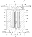
- FIG. 2 is a cross-sectional view schematically showing the electrolytic cell 11.
- the electrolytic cell 11 includes, for example, a first separator 41, a second separator 42, and a membrane electrode assembly 43.
- the first separator 41 is a member that defines one surface of the internal space S of the electrolytic cell 11.
- the internal space S is a space including a cathode chamber Sa and an anode chamber Sb, which will be described later.
- the first separator 41 has a rectangular plate shape, for example, and is made of a metal member. For example, a negative voltage is applied to the first separator 41 from the power supply unit 30 via a first current collector 61 (see FIG. 3), which will be described later.
- the first separator 41 has a first end 41e1 (for example, a lower end) and a second end 41e2 (for example, an upper end) located on the opposite side of the first end 41e1.
- the above-mentioned piping line L1 is connected to the first end 41e1 of the first separator 41.
- the above-mentioned piping line L2 is connected to the second end portion 41e2 of the first separator 41.
- the first separator 41 has a first inner surface 41a facing a cathode chamber Sa, which will be described later.
- a first flow path FP1 is formed in the first inner surface 41a, through which the electrolytic solution supplied from the piping line L1 flows.
- the first flow path FP1 is, for example, a groove provided in the first inner surface 41a.
- the electrolytic solution that has flowed through the first flow path FP1 is discharged to the outside of the electrolytic cell 11 through the piping line L2.
- each structure for example, a flow path structure, etc.
- FIG. 2 is merely an example, and does not limit the content of this embodiment.
- various structures can be used for the channel structure depending on the size, purpose, and usage environment of the device. This also applies to each structure shown in other figures.
- the second separator 42 is a member that is arranged with an internal space S between it and at least a portion of the first separator 41, and defines the other surface of the internal space S.
- the second separator 42 has a rectangular plate shape, for example, and is made of a metal member.
- a positive voltage is applied to the second separator 42 from the power supply unit 30 via a second current collector 62 (see FIG. 3), which will be described later.
- the first separator 41 and the second separator 42 included in the same electrolytic cell 11 form the electrolytic bath 40 of the electrolytic cell 11 as a pair of separators.
- the second separator 42 has a first end 42e1 (for example, a lower end) and a second end 42e2 (for example, an upper end) located on the opposite side of the first end 42e1.
- the above-mentioned piping line L3 is connected to the first end 42e1 of the second separator 42.
- the above-mentioned piping line L4 is connected to the second end portion 42e2 of the second separator 42.
- the second separator 42 has a second inner surface 42a facing an anode chamber Sb, which will be described later.
- a second flow path FP2 through which the electrolytic solution supplied from the piping line L3 flows is formed in the second inner surface 42a.
- the second flow path FP2 is, for example, a groove provided in the second inner surface 42a.
- the electrolytic solution that has flowed through the second flow path FP2 is discharged to the outside of the electrolytic cell 11 through the piping line L4.
- the first inner surface 41a of the first separator 41 has a channel groove (first channel FP1)
- the second inner surface 42a of the second separator 42 has a channel groove (first channel FP1).
- a configuration having two flow paths FP2) is described.
- the first separator 41 of the electrolytic cell 11 included in the electrolytic cell stack 10 has a similar flow path on the surface 41b opposite to the first inner surface 41a in addition to the first inner surface 41a.
- a bipolar plate having a groove first flow path FP1, shown by a two-dot chain line in FIG. 2 may be used.
- the second separator 42 of the electrolytic cell 11 included in the electrolytic cell stack 10 has a similar channel groove (a second flow channel A bipolar plate having a path FP2 (indicated by a two-dot chain line in FIG. 2) may also be used.
- a second flow channel A bipolar plate having a path FP2 (indicated by a two-dot chain line in FIG. 2) may also be used.
- the flow channel grooves provided on both sides of the first separator 41 may have different shapes and arrangements.
- the flow path grooves provided on both sides of the second separator 42 may have different shapes and arrangements.
- the membrane electrode assembly (MEA) 43 is a structure in which an ion exchange membrane, a catalyst, and a power supply are assembled.
- the membrane electrode assembly 43 is arranged between the first separator 41 and the second separator 42, and is located in the internal space S.
- the membrane electrode assembly 43 includes, for example, a first ion exchange membrane 51, a second ion exchange membrane 52, an ionomer layer 53, a cathode catalyst layer 54, a cathode power supply 55, an anode catalyst layer 56, and an anode power supply 57.
- the first ion exchange membrane 51 is a membrane that selectively permeates ions.
- the first ion exchange membrane 51 is, for example, a solid polymer electrolyte membrane.
- the first ion exchange membrane 51 is, for example, an anion exchange membrane (AEM) having hydroxide ion conductivity.
- AEM anion exchange membrane
- the first ion exchange membrane 51 is not limited to the above example, and may be an ion exchange membrane of a different type from the above example.
- the first ion exchange membrane 51 is, for example, in the shape of a rectangular sheet.
- the outer size of the first ion exchange membrane 51 is smaller than the outer size of the first separator 41 or the second separator 42 .
- the first ion exchange membrane 51 is disposed between the first separator 41 and the second separator 42, and is located in the internal space S described above.
- the first ion exchange membrane 51 has a first surface 51a facing the first inner surface 41a of the first separator 41, and a second surface 51b located on the opposite side to the first surface 51a.
- a cathode chamber Sa is defined between the first surface 51a of the first ion exchange membrane 51 and the first inner surface 41a of the first separator 41.
- the second ion exchange membrane 52 is a membrane that selectively permeates ions.
- the second ion exchange membrane 52 is, for example, a solid polymer electrolyte membrane.
- the second ion exchange membrane 52 is, for example, an anion exchange membrane with hydroxide ion conductivity.
- the second ion exchange membrane 52 is not limited to the above example, and may be a different type of ion exchange membrane from the above example.
- the second ion exchange membrane 52 is, for example, in the shape of a rectangular sheet.
- the outer size of the second ion exchange membrane 52 is smaller than the outer size of the first separator 41 or the second separator 42 .
- the outer size of the second ion exchange membrane 52 is the same as the outer size of the first ion exchange membrane 51.
- the second ion exchange membrane 52 is disposed between the first separator 41 and the second separator 42, and is located in the internal space S described above.
- the second ion exchange membrane 52 has a third surface 52a facing the second inner surface 42a of the second separator 42, and a fourth surface 52b located on the opposite side to the third surface 52a.
- an anode chamber Sb is defined between the third surface 52a of the second ion exchange membrane 52 and the second inner surface 42a of the second separator 42.
- ordinal numbers such as “first” and “second” attached to names of constituent elements are for convenience of explanation.
- the names “third” and “fourth” do not assume that the names “first” and “second” exist for the same member.
- the names “third surface 52a” and “fourth surface 52b” of the second ion exchange membrane 52 are based on the premise that the second ion exchange membrane 52 has a first surface and a second surface. It's not something you do. Therefore, the names “third surface 52a” and “fourth surface 52b” may be read as “first surface 52a” and "second surface 52b" of the second ion exchange membrane 52.
- the first ion exchange membrane 51 and the second ion exchange membrane 52 are integrated with the second surface 51b of the first ion exchange membrane 51 and the fourth surface 52b of the second ion exchange membrane 52 facing each other. has been done.
- "the first ion exchange membrane 51 and the second ion exchange membrane 52 are integrated" is limited to the case where the first ion exchange membrane 51 and the second ion exchange membrane 52 are directly combined.
- another layer for example, an ionomer layer 53 to be described later
- the materials of the first ion exchange membrane 51 and the second ion exchange membrane 52 may be the same or different.
- the materials of the first ion exchange membrane 51 and the second ion exchange membrane 52 are selected as follows. That is, since no oxidation reaction occurs in the cathode chamber Sa, the first ion exchange membrane 51 does not need to have high oxidation resistance. Therefore, as the first ion exchange membrane 51, for example, a membrane made of a material having higher ionic conductivity than the second ion exchange membrane 52 is used. On the other hand, since an oxidation reaction occurs in the anode chamber Sb, it is preferable that the second ion exchange membrane 52 has high oxidation resistance. Therefore, as the second ion exchange membrane 52, for example, a membrane made of a material with higher oxidation resistance than the first ion exchange membrane 51 is employed.
- An example of a “membrane with high ionic conductivity” is a membrane containing a polystyrene-based or tetraphenyl-based composition in the main chain and an imidazolium group or a quaternary ammonium group in the side chain.
- the "highly oxidation-resistant film” is, for example, a film containing a polysulfone-based or bromobutylstyrene-based composition.
- the ionomer layer 53 is a layer for bonding the first ion exchange membrane 51 and the second ion exchange membrane 52.
- the ionomer layer 53 is a layer through which hydroxide ions can pass.
- the ionomer layer 53 is provided between the second surface 51b of the first ion exchange membrane 51 and the fourth surface 52b of the second ion exchange membrane 52.
- the ionomer layer 53 is provided over the entire second surface 51b of the first ion exchange membrane 51 and over the entire fourth surface 52b of the second ion exchange membrane 52.
- the thickness of the ionomer layer 53 is, for example, 10 nm or more and 10 ⁇ m or less.
- the first ion exchange membrane 51 and the second ion exchange membrane 52 are integrated via the ionomer layer 53.
- the cathode catalyst layer 54 is a layer that promotes the chemical reaction in the cathode chamber Sa described above.
- the cathode catalyst layer 54 is, for example, in the shape of a rectangular sheet.
- the external size of the cathode catalyst layer 54 is smaller than the external size of the first ion exchange membrane 51.
- the cathode catalyst layer 54 is arranged in the cathode chamber Sa, and is adjacent to the first ion exchange membrane 51. Note that "adjacent" in this application is not limited to the case where two members are independently adjacent to each other, and at least a portion of one of the two members may enter the other member.
- a portion of the cathode catalyst layer 54 may enter the surface of the first ion exchange membrane 51.
- the cathode catalyst layer 54 is provided on the first surface 51a of the first ion exchange membrane 51.
- the cathode catalyst layer 54 is formed by applying the material of the cathode catalyst layer 54 to the first surface 51a of the first ion exchange membrane 51.
- a negative voltage is applied to the cathode catalyst layer 54 from the power supply section 30 via the first separator 41 and the cathode power supply body 55, and the cathode catalyst layer 54 functions as a part of the cathode 47 of the battery cell 11.
- the material for the cathode catalyst layer 54 may be any material that promotes the chemical reaction in the cathode chamber Sa, and various materials can be used.
- the cathode catalyst layer 54 contains at least one of nickel, nickel alloy, cerium oxide, lanthanum oxide, and platinum.
- XX oxide may contain another material (another element) other than XXX and oxygen.
- the cathode catalyst layer 54 may contain another material such as carbon in addition to the above-mentioned materials.
- the cathode power supply body 55 is an electrical connection part that transmits the voltage applied to the first separator 41 to the cathode catalyst layer 54.
- the cathode power supply body 55 is arranged in the cathode chamber Sa.
- the cathode power supply body 55 is located between the first inner surface 41a of the first separator 41 and the cathode catalyst layer 54, and is in contact with the first inner surface 41a of the first separator 41 and the cathode catalyst layer 54, respectively. Note that at least a portion of the cathode power supply body 55 may overlap at least a portion of at least one of the first separator 41 and the cathode catalyst layer 54.
- the cathode power supply body 55 has a structure through which an electrolytic solution and gas can pass.
- the cathode power supply body 55 is formed of, for example, a metal mesh structure, a sintered body, a fiber, or the like.
- the external size of the cathode power supply body 55 is the same as the external size of the cathode catalyst layer 54.
- the cathode 47 of the battery cell 11 is formed by the cathode catalyst layer 54 and the cathode power supply body 55.
- the anode catalyst layer 56 is a layer that promotes the chemical reaction in the anode chamber Sb described above.
- the anode catalyst layer 56 is, for example, in the shape of a rectangular sheet.
- the external size of the anode catalyst layer 56 is smaller than the external size of the second ion exchange membrane 52.
- the anode catalyst layer 56 is arranged in the anode chamber Sb and is adjacent to the second ion exchange membrane 52. Note that, for example, a portion of the anode catalyst layer 56 may enter the surface portion of the second ion exchange membrane 52.
- the anode catalyst layer 56 is provided on the third surface 52a of the second ion exchange membrane 52.
- the anode catalyst layer 56 is formed by applying the material of the anode catalyst layer 56 to the third surface 52a of the second ion exchange membrane 52.
- a positive voltage is applied to the anode catalyst layer 56 from the power supply section 30 via the second separator 42 and the anode power supply body 57, and the anode catalyst layer 56 functions as a part of the anode 48 of the battery cell 11.
- the material of the anode catalyst layer 56 may be any material that promotes the chemical reaction in the anode chamber Sb described above, and various materials can be used.
- the anode catalyst layer 56 includes at least one of nickel, nickel alloy, nickel oxide, copper oxide, iridium oxide, niobium oxide, lead oxide, and bismuth oxide.
- the "XX oxide” may contain another material (another element) other than XX and oxygen.
- nickel oxide may contain elements such as iron and cobalt in addition to nickel and oxygen.
- the "copper oxide” may contain elements such as cobalt in addition to copper and oxygen.
- Iridium oxide may contain elements such as ruthenium in addition to iridium and oxygen.
- Lead oxide may contain elements such as ruthenium in addition to lead and oxygen.
- “Bismuth oxide” may contain elements such as ruthenium in addition to bismuth and oxygen.
- the anode power supply body 57 is an electrical connection part that transmits the voltage applied to the second separator 42 to the anode catalyst layer 56.
- the anode power supply body 57 is arranged in the anode chamber Sb.
- the anode power supply body 57 is located between the second inner surface 42a of the second separator 42 and the anode catalyst layer 56, and is in contact with the second inner surface 42a of the second separator 42 and the anode catalyst layer 56, respectively. Note that at least a portion of the anode power supply body 57 may overlap at least a portion of at least one of the second separator 42 and the anode catalyst layer 56.
- the anode power supply body 57 has a structure through which an electrolytic solution and gas can pass.
- the anode power supply body 57 is formed of, for example, a metal mesh structure, a sintered body, a fiber, or the like.
- the external size of the anode power supply body 57 is the same as the external size of the anode catalyst layer 56.
- the anode 48 of the battery cell 11 is formed by the anode catalyst layer 56 and the anode power supply body 57.
- FIG. 3 is an exploded perspective view showing the electrolytic cell 11.
- the electrolytic cell 11 includes, for example, a first current collector 61, a second current collector 62, a first insulator 63, a second insulator 64, a first insulator 65, and a second insulator 66. , a first end plate 67, and a second end plate 68. Note that in FIG. 3, for convenience of explanation, illustrations of a support portion 70 and a sealing portion 80, which will be described later, are omitted.
- the first current collector 61 is an electrical connection part that transmits a negative voltage applied from the power supply section 30 to the first separator 41.
- the first current collector 61 is a metal plate member (for example, a copper plate).
- the first current collector 61 contacts the first separator 41 from the side opposite to the internal space S of the electrolytic cell 11 and is electrically connected to the first separator 41 .
- a negative voltage necessary for electrolysis in the electrolytic cell 11 is applied to the first current collector 61 from the power supply section 30 .
- the first current collector 61 may be shared by two electrolytic cells 11 adjacent to each other in the electrolytic cell stack 10.
- the second current collector 62 is an electrical connection section that transmits the positive voltage applied from the power supply section 30 to the second separator 42 .
- the second current collector 62 is a metal plate member (for example, a copper plate).
- the second current collector 62 contacts the second separator 42 from the side opposite to the internal space S of the electrolytic cell 11 and is electrically connected to the second separator 42 .
- a positive voltage necessary for electrolysis in the electrolytic cell 11 is applied to the second current collector 62 from the power supply section 30 .
- the second current collector 62 may be shared by two electrolytic cells 11 adjacent to each other in the electrolytic cell stack 10.
- the first insulator 63 is a member that insulates between the outer circumference of the first separator 41 and the outer circumference of the second separator 42 .
- the first insulator 63 is a frame-shaped sheet member that is slightly larger than the outer shape of the cathode catalyst layer 54 and the outer shape of the cathode power supply body 55 .
- the first insulator 63 is attached to the first inner surface 41a of the first separator 41 and covers the end of the first inner surface 41a.
- the material of the first insulator 63 is not particularly limited as long as it is an insulating material, and is, for example, a sheet-shaped resin such as PTFE (polytetrafluoroethylene).
- the second insulator 64 is a member that insulates between the outer circumference of the first separator 41 and the outer circumference of the second separator 42.
- the second insulator 64 is a frame-shaped sheet member that is slightly larger than the outer shape of the anode catalyst layer 56 and the outer shape of the anode power supply body 57 .
- the second insulator 64 is attached to the second inner surface 42a of the second separator 42 and covers the end of the second inner surface 42a.
- the material of the second insulator 64 is not particularly limited as long as it is an insulating material, and is, for example, a sheet-shaped resin such as PTFE.
- the first insulator 63 and the second insulator 64 can also be used as an integrated insulator.
- the first insulating material 65 is located between the first current collector 61 and the first end plate 67.
- the outer size of the first insulating material 65 is, for example, the same as the outer size of the first current collector 61 or larger than the outer size of the first current collector 61.
- the second insulating material 66 is located between the second current collector 62 and the second end plate 68.
- the external size of the second insulating material 66 is, for example, the same as the external size of the second current collector 62, or larger than the external size of the second current collector 62.
- the first end plate 67 is located on the opposite side of the first insulating material 65 with respect to the internal space S of the electrolytic cell 11 .
- the outer size of the first end plate 67 is larger than the outer size of the first insulating material 65, for example.
- the second end plate 68 is located on the opposite side of the second insulating material 66 with respect to the internal space S of the electrolytic cell 11 .
- the outer size of the second end plate 68 is larger than the outer size of the second insulating material 66, for example.
- the electrolytic cell 11 is not limited to the configuration described above.
- two adjacent electrolytic cells 11 among the plurality of electrolytic cells 11 are separated by a first separator 41 or a second separator 42, respectively, which are bipolar plates. may be shared.
- a current collector first current collector 61 or second current collector 62
- an insulator first insulator 63 or second insulator 64
- the insulating material the first insulating material 65 or the second insulating material 66
- the end plate the first end plate 67 or the second end plate 68
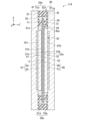
- FIG. 4 is a sectional view showing the electrolytic cell 11.
- the outer size of the first ion exchange membrane 51 is larger than each of the outer size of the cathode catalyst layer 54 and the outer size of the cathode power supply body 55.
- the area of the first ion exchange membrane 51 is larger than each of the area of the cathode catalyst layer 54 and the area of the cathode power supply body 55.
- the first ion exchange membrane 51 is located outside (the outer periphery) of the cathode catalyst layer 54 and the cathode power supply body 55 in a direction (for example, the X direction or the Y direction) perpendicular to the thickness direction (Z direction) of the membrane electrode assembly 43. protruding from the side).
- “outside” or “outer peripheral side” refers to the central part of the membrane electrode assembly 43 in a direction (for example, the X direction or the Y direction) orthogonal to the thickness direction (Z direction) of the membrane electrode assembly 43. It means the side away from C.
- the external size of the second ion exchange membrane 52 is larger than each of the external sizes of the anode catalyst layer 56 and the anode power supply body 57.
- the area of the second ion exchange membrane 52 is larger than each of the area of the anode catalyst layer 56 and the area of the anode power supply body 57.
- the second ion exchange membrane 52 is located closer to the outer periphery than the anode catalyst layer 56 and the anode power supply body 57 in a direction (for example, the X direction or the Y direction) perpendicular to the thickness direction (Z direction) of the membrane electrode assembly 43. It stands out.
- the first ion exchange membrane 51 and the second ion exchange membrane 52 are collectively referred to as an "ion exchange membrane stack 59.”
- the electrolytic cell 11 includes, for example, a support portion 70 and a sealing portion 80.
- the support part 70 is a member that supports the membrane electrode assembly 43 inside the electrolytic cell 11.
- the sealing part 80 is a member that closes the internal space S between the first separator 41 and the second separator 42.
- the support part 70 is arranged between the first separator 41 and the second separator 42.
- the support portion 70 is located inside (on the inner peripheral side) of the outer edge portion 59e of the ion exchange membrane stack 59 and supports the ion exchange membrane stack 59.
- the “outer edge portion” refers to a portion away from the central portion C of the membrane electrode assembly 43 in a direction (for example, the X direction or the Y direction) orthogonal to the thickness direction (Z direction) of the membrane electrode assembly 43. means the edge.
- “inner side” or “inner peripheral side” means the inner side (the side closer to the center C) when viewed from the center C of the membrane electrode assembly 43.
- the support section 70 includes, for example, a first support section 71 and a second support section 72.
- the first support section 71 is a support section on the cathode side.
- the first support portion 71 is arranged between the first inner surface 41a of the first separator 41 and the first surface 51a of the first ion exchange membrane 51.
- the first support portion 71 is located inside (on the inner peripheral side) of the outer edge portion 59e of the ion exchange membrane stack 59 (for example, the outer edge portion 51e of the first ion exchange membrane 51).
- the first support portion 71 connects the first inner surface 41a (or the first insulator 63) of the first separator 41 and the first ion exchange membrane 51 at a position outside (outer circumferential side) of the cathode catalyst layer 54 and the cathode power supply body 55.
- the first ion exchange membrane 51 is supported against the first inner surface 41a of the first separator 41.
- the first support portion 71 has an annular shape (for example, a frame shape) along the outer edge 51e of the first ion exchange membrane 51, and is formed in an annular shape that is one size smaller than the outer edge 51e of the first ion exchange membrane 51.
- the second support portion 72 is a support portion on the anode side.
- the second support portion 72 is arranged between the second inner surface 42a of the second separator 42 and the third surface 52a of the second ion exchange membrane 52.
- the second support portion 72 is located inside (on the inner peripheral side) of the outer edge 59e of the ion exchange membrane stack 59 (for example, the outer edge 52e of the second ion exchange membrane 52).
- the second support portion 72 is located between the second inner surface 42a of the second separator 42 and the third surface 52a of the second ion exchange membrane 52 at a position outside (outer circumferential side) of the anode catalyst layer 56 and the anode power supply body 57.
- the second ion exchange membrane 52 is supported against the second inner surface 42a of the second separator 42.
- the second support portion 72 has an annular shape (for example, a frame shape) along the outer edge portion 52e of the second ion exchange membrane 52, and is formed in an annular shape that is one size smaller than the outer edge portion 52e of the second ion exchange membrane 52.
- the sealing part 80 is arranged between the first separator 41 and the second separator 42.
- the sealing portion 80 is located outside (on the outer peripheral side) of the outer edge 59e of the ion exchange membrane stack 59 (that is, the outer edge 51e of the first ion exchange membrane 51 and the outer edge 52e of the second ion exchange membrane 52). Then, the internal space S of the electrolytic cell 11 is sealed.
- the sealing section 80 includes a first sealing section 81 and a second sealing section 82 .
- the first sealing part 81 and the second sealing part 82 may be formed integrally. That is, the first sealing part 81 and the second sealing part 82 may be one member.
- the sealing part 80 may be formed integrally with at least one of the first insulator 63 and the second insulator 64 described above.
- the first sealing part 81 is a sealing part on the cathode side.
- the first sealing portion 81 is located outside (on the outer peripheral side) of the outer edge portion 59e of the ion exchange membrane stack 59.
- the first sealing part 81 is sandwiched between the first inner surface 41a of the first separator 41 and the second sealing part 82, and seals a part of the outer peripheral side of the internal space S.
- the first sealing part 81 is annular (for example, frame-shaped) along the outer edge 51e of the first ion exchange membrane 51, and is formed in an annular shape that is one size larger than the outer edge 51e of the first ion exchange membrane 51.
- the second sealing part 82 is a sealing part on the anode side.
- the second sealing portion 82 is located outside the outer edge portion 59e of the ion exchange membrane stack 59.
- the second sealing part 82 is sandwiched between the second inner surface 42a of the second separator 42 and the first sealing part 81, and seals a part of the outer peripheral side of the internal space S.
- the second sealing portion 82 is annular (for example, frame-shaped) along the outer edge 52e of the second ion exchange membrane 52, and is formed in an annular shape that is one size larger than the outer edge 52e of the second ion exchange membrane 52.
- FIG. 5 is a cross-sectional view showing a method of manufacturing the membrane electrode assembly 43.
- the cathode catalyst layer 54 is provided on the first surface 51a of the first ion exchange membrane 51.
- the cathode catalyst layer 54 is formed by applying (coating) the material of the cathode catalyst layer 54 to the first surface 51a of the first ion exchange membrane 51, and combining the applied material of the cathode catalyst layer 54 with the first ion exchange membrane 51. It is formed by pressing under a predetermined temperature and predetermined pressure.
- an anode catalyst layer 56 is provided on the third surface 52a of the second ion exchange membrane 52.
- the anode catalyst layer 56 is formed by applying (coating) the material of the anode catalyst layer 56 to the third surface 52a of the second ion exchange membrane 52, and combining the applied material of the anode catalyst layer 56 with the second ion exchange membrane 52. It is formed by pressing under a predetermined temperature and predetermined pressure.
- the material of the cathode catalyst layer 54 and the material of the anode catalyst layer 56 can be applied by, for example, a coating method, a CVD (Chemical Vapor Deposition) method, an electroless plating method, a method using catalyst ink, or a method of applying the catalyst by spraying. can be used as appropriate.
- the step of providing the cathode catalyst layer 54 on the first ion exchange membrane 51 and the step of providing the anode catalyst layer 56 on the second ion exchange membrane 52 are performed by This is done before integrating the Further, the step of providing the cathode catalyst layer 54 on the first ion exchange membrane 51 and the step of providing the anode catalyst layer 56 on the second ion exchange membrane 52 are performed as mutually independent steps (separate steps). Therefore, the step of providing the cathode catalyst layer 54 on the first ion exchange membrane 51 does not or hardly affects the step of providing the anode catalyst layer 56 on the second ion exchange membrane 52. Conversely, the process of providing the anode catalyst layer 56 on the second ion exchange membrane 52 does not or hardly affects the process of providing the cathode catalyst layer 54 on the first ion exchange membrane 51.
- the first ion exchange membrane 51 and the second ion exchange membrane 52 are connected to They are integrated with each other with the fourth surface 52b facing each other.
- the material of the ionomer layer 53 is applied to the second surface 51b of the first ion exchange membrane 51 and the fourth surface 52b of the second ion exchange membrane 52, respectively.
- the second surface 51b of the first ion exchange membrane 51 and the fourth surface 52b of the second ion exchange membrane 52 are pressed at a predetermined temperature and a predetermined pressure while facing each other. and are bonded via the ionomer layer 53.
- a cathode power supply body 55 is coupled to the cathode catalyst layer 54 from the side opposite to the first ion exchange membrane 51.
- the cathode power supply body 55 is bonded to the cathode catalyst layer 54 by applying pressure, for example, by pressing.
- an anode power supply body 57 is connected to the anode catalyst layer 56 from the side opposite to the second ion exchange membrane 52 .
- the anode power supply body 57 is bonded to the anode catalyst layer 56 by applying pressure, for example, by pressing. Thereby, the membrane electrode assembly 43 is completed.
- the membrane electrode assembly 43 includes a first ion exchange membrane 51 and a second ion exchange membrane 52.
- the first ion exchange membrane 51 and the second ion exchange membrane 51 are connected.
- the two ion exchange membranes 52 it is suppressed that uneven parts of the catalyst layer on one side of the ion exchange membrane affect the production of the catalyst layer on the other side of the ion exchange membrane. can do. Thereby, it is possible to suppress the occurrence of locations that may cause problems such as short circuits.
- the stability of the performance of the membrane electrode assembly 43 can be improved. Furthermore, if it becomes easier to uniformly provide the catalyst layer on the surface of the ion exchange membrane, it becomes easier to reduce the thickness of the ion exchange membrane (the thickness of the first ion exchange membrane 51 and the second ion exchange membrane 52). If the thickness of the ion exchange membrane can be reduced, the performance of the membrane electrode assembly 43 can be improved. Furthermore, in this embodiment, two ion exchange membranes each having a catalyst layer on one side can be handled separately, so handling in the manufacturing process becomes easier and productivity can be improved.
- FIG. 6 is a sectional view showing an electrolytic cell 11 according to a modification of the first embodiment.
- the ionomer layer 53 is provided between the first ion exchange membrane 51 and the second ion exchange membrane 52.
- the ionomer layer 53 is not provided between the first ion exchange membrane 51 and the second ion exchange membrane 52. That is, the second surface 51b of the first ion exchange membrane 51 and the fourth surface 52b of the second ion exchange membrane 52 are in contact with each other.
- the first ion exchange membrane 51 and the second ion exchange membrane 52 are pressed with the second surface 51b of the first ion exchange membrane 51 and the fourth surface 52b of the second ion exchange membrane 52 facing each other (pressing). be integrated).
- the step of providing the cathode catalyst layer 54 on the first ion exchange membrane 51 and the step of providing the anode catalyst layer 56 on the second ion exchange membrane 52 can be performed separately, so that the ion exchange membrane It is possible to prevent uneven portions of the catalyst layer existing on one surface from affecting the production of the catalyst layer on the other surface of the ion exchange membrane.
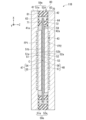
- the second embodiment differs from the first embodiment in that the area of the anode 48 is larger than the area of the cathode 47. Note that the configuration other than those described below is the same as the configuration of the first embodiment.
- FIG. 7 is a cross-sectional view showing an electrolytic cell 11A of the second embodiment.
- the area of the anode 48 is larger than the area of the cathode 47.
- the area of the anode catalyst layer 56 is larger than the area of the cathode catalyst layer 54.
- the area of the anode power supply body 57 is larger than the area of the cathode power supply body 55.
- the area ratio of the anode 48 to the cathode 47 is greater than 1.0 and 1.3 or less. From another perspective, in this embodiment, the area ratio of the anode 48 to the cathode 47 is such that the rate of increase in the overvoltage of the anode 48 as deterioration progresses is less than twice (more preferably is set to be less than 1.5 times). These contents will be explained in detail below.
- FIG. 8 is a diagram for explaining the action of the electrolytic cell 11A.
- FIG. 8 is a diagram showing test results of current-voltage characteristics in an electrolytic cell of a second comparative example in which the area of the anode and the area of the cathode are the same.
- cycle means a predetermined period of time set in advance. As shown in FIG. 8, it can be seen that in the electrolytic cell of the second comparative example, the overvoltage increases as the number of cycles increases (that is, as the usage time increases).
- FIG. 9 is another diagram for explaining the action of the electrolytic cell 11A.
- FIG. 9 is a diagram showing the test results of the relationship between the number of cycles and the reaction resistance in the electrode in the second comparative example.
- the reaction resistance at the anode 48 has a larger absolute value than the reaction resistance at the cathode 47.
- the rate of increase in the reaction resistance at the anode 48 as the deterioration progresses is greater than the rate of increase in the reaction resistance at the cathode 47 as the deterioration progresses.
- the rate of increase in reaction resistance at the anode 48 is more than twice the rate of increase in reaction resistance at the cathode 47. This is because an oxidation reaction occurs in the anode 48, so that the deterioration of the anode 48 is greater than the deterioration of the cathode 47.
- the area of the anode 48 is formed larger than the area of the cathode 47. According to such a configuration, the oxidation reaction at the anode 48 can be dispersed over a wide area of the anode 48. Thereby, compared to Comparative Example 2, it is possible to suppress the deterioration of the anode 48 from being greater than that of the cathode 47. If it is possible to suppress the deterioration of the anode 48 to be greater than that of the cathode 47, it is possible to suppress an increase in overvoltage, and it is possible to improve the performance and life of the electrolytic cell 11A.
- the cathode catalyst layer 54 is provided on the first ion exchange membrane 51, and the anode catalyst layer 56 is provided on the second ion exchange membrane 52. According to such a configuration, the cathode catalyst layer 54 and the anode catalyst layer 56 having different areas can be easily formed. Therefore, according to this embodiment, it is possible to improve the productivity of the membrane electrode assembly 43 in which the area of the anode 48 is larger than the area of the cathode 47.
- the anode catalyst layer 56 is larger than the cathode catalyst layer 54, the ends of each catalyst layer where the current density becomes high are located offset from each other. As a result, deterioration is less likely to occur at the ends of each catalyst layer. Also from this point of view, it is possible to suppress an increase in overvoltage, and it is possible to improve the performance and life of the electrolytic cell 11A.
- the test results of the relationship between the number of cycles and the reaction resistance at the electrode in the second comparative example show that the rate of increase in the reaction resistance at the anode 48 was 2% compared to the rate of increase in the reaction resistance at the cathode 47. That's more than double that.
- the area ratio of the anode 48 to the cathode 47 is set based on the rate of increase in reaction resistance at the anode 48 and the rate of increase in reaction resistance at the cathode 47.
- the area ratio of the anode 48 to the cathode 47 is such that the difference between the rate of increase in reaction resistance at the anode 48 and the rate of increase in the reaction resistance at the cathode 47 is equal to or less than a predetermined standard (for example, less than 2 times, more preferably less than 1.5 times). ) is adjusted and determined.
- a predetermined standard for example, less than 2 times, more preferably less than 1.5 times.
- the amount of catalyst supported on the anode catalyst layer 56 is the same as or greater than the amount of catalyst supported on the cathode catalyst layer 54.
- the "catalyst supported amount” in the present disclosure means the weight of the catalyst per unit area [mg/cm 2 ].
- the third embodiment differs from the second embodiment in that the thickness of the anode catalyst layer 56 is greater than the thickness of the cathode catalyst layer 54. Note that the configuration other than those described below is the same as the configuration of the second embodiment.
- FIG. 10 is a sectional view showing an electrolytic cell 11B of the third embodiment.
- the area of the anode catalyst layer 56 is larger than the area of the cathode catalyst layer 54, and the thickness of the anode catalyst layer 56 is larger than the thickness of the cathode catalyst layer 54.
- the amount of catalyst supported on the anode catalyst layer 56 is the same as or greater than the amount of catalyst supported on the cathode catalyst layer 54.
- the volume ratio (or catalyst loading ratio) of the anode catalyst layer 56 to the cathode catalyst layer 54 is such that the rate of increase in the overvoltage of the anode 48 as deterioration progresses is 2 compared to the rate of increase in the overvoltage of the cathode 47. It is set to be less than twice (more preferably less than 1.5 times). In other words, the volume ratio of the anode 48 to the cathode 47 is such that the difference between the rate of increase in reaction resistance at the anode 48 and the rate of increase in the reaction resistance at the cathode 47 is equal to or less than a predetermined standard (for example, less than 2 times, more preferably 1.5 times). (less than).
- the member that connects the first ion exchange membrane 51 and the second ion exchange membrane 52 is not limited to the ionomer layer 53, but may be an adhesive layer made of another material having hydroxide ion conductivity.
- the membrane electrode assembly 43 includes a first ion exchange membrane 51, a second ion exchange membrane 52, a cathode catalyst layer 54, and an anode catalyst layer 56.
- the first ion exchange membrane 51 includes a first surface 51a and a second surface 51b located on the opposite side to the first surface 51a.
- the second ion exchange membrane 52 includes a third surface 52a and a fourth surface 52b located on the opposite side of the third surface 52a.
- the cathode catalyst layer 54 is provided on the first surface 51a of the first ion exchange membrane 51.
- the anode catalyst layer 56 is provided on the third surface 52a of the second ion exchange membrane 52.
- the first ion exchange membrane 51 and the second ion exchange membrane 52 are anion exchange membranes having hydroxide ion conductivity. It is integrated with the surface 52b facing each other. According to such a configuration, it is possible to suppress the occurrence of locations that cause problems such as short circuits. As a result, the stability of the performance of the electrolytic device 1 can be improved. Furthermore, since the two ion exchange membranes each having a catalyst layer on one side can be handled separately, handling becomes easier and productivity can be improved.
- the membrane electrode assembly 43 according to the second aspect is the membrane electrode assembly 43 according to the first aspect, and includes a second surface 51b of the first ion exchange membrane 51 and a fourth surface of the second ion exchange membrane 52.
- An ionomer layer 53 may be further provided between the surface 52b and the surface 52b. According to such a configuration, the first ion exchange membrane 51 and the second ion exchange membrane 52 can be bonded well through the ionomer layer 53. Thereby, it is possible to improve the stability of the performance of the electrolyzer 1 at a higher level.
- the membrane electrode assembly 43 according to the third aspect is the membrane electrode assembly 43 according to the first or second aspect, and the thickness of the ionomer layer 53 may be 10 nm or more and 10 ⁇ m or less. . According to such a configuration, the first ion exchange membrane 51 and the second ion exchange membrane 52 can be bonded well through the ionomer layer 53 having an appropriate thickness. Thereby, it is possible to improve the stability of the performance of the electrolyzer 1 at a higher level.
- the membrane electrode assembly 43 according to the fourth aspect is the membrane electrode assembly 43 according to any one of the first to third aspects, in which the second surface 51b of the first ion exchange membrane 51 and The fourth surface 52b of the second ion exchange membrane 52 may be in contact with it. According to such a configuration, the first ion exchange membrane 51 and the second ion exchange membrane 52 are integrated without using the ionomer layer 53. Thereby, it may be possible to further improve the performance of the electrolyzer 1.
- the membrane electrode assembly 43 according to the fifth aspect is the membrane electrode assembly 43 according to any one of the first to fourth aspects, and the cathode catalyst layer 54 is made of nickel, nickel alloy, cerium, etc. oxide, lanthanum oxide, and platinum, and the anode catalyst layer 56 may contain at least one of nickel, nickel alloy, nickel oxide, copper oxide, iridium oxide, niobium oxide, and lead. It may contain at least one of an oxide and a bismuth oxide. According to such a configuration, it is possible to cause appropriate reactions at the cathode 47 and the anode 48, respectively.
- the membrane electrode assembly 43 according to the sixth aspect is the membrane electrode assembly 43 according to any one of the first to fifth aspects, and includes a first ion exchange membrane 51 and a second ion exchange membrane.
- the material may be different from that of 52. According to such a configuration, it is possible to further improve the performance of the electrolytic device 1.
- the membrane electrode assembly 43 according to the seventh aspect is the membrane electrode assembly 43 according to any one of the first to sixth aspects, and the material of the second ion exchange membrane 52 is the first The material may have higher oxidation resistance than the material of the ion exchange membrane 51. According to such a configuration, deterioration of the anode 48 can be suppressed from becoming greater than deterioration of the cathode 47.
- the membrane electrode assembly 43 according to the eighth aspect is the membrane electrode assembly 43 according to any one of the first to seventh aspects, and the material of the first ion exchange membrane 51 is The material may have higher ionic conductivity than the material of the ion exchange membrane 52. According to such a configuration, the performance of the electrolytic device 1 can be further improved.
- the membrane electrode assembly 43 according to the ninth aspect is the membrane electrode assembly 43 according to any one of the first to eighth aspects, in which the area of the anode 48 is larger than the area of the cathode 47. It can be large. According to such a configuration, deterioration of the anode 48 can be suppressed from becoming greater than deterioration of the cathode 47. As a result, it is possible to improve the performance and life of the electrolytic cells 11A and 11B.
- the membrane electrode bonding member 43 according to the tenth aspect is the membrane electrode assembly 43 according to the first aspect, and the amount of catalyst supported in the anode catalyst layer 56 is the same as the amount of catalyst supported in the cathode catalyst layer 54. Or it may be more.
- the electrolytic cells 11, 11A, 11B include a first separator 41, a second separator 42, and a first to second separator 42 disposed between the first separator 41 and the second separator 42.
- the membrane electrode assembly 43 according to any one of the ten aspects is provided. According to such a configuration, it is possible to improve stability of performance and productivity of the electrolytic cells 11, 11A, and 11B.
- the electrolytic device 1 includes the electrolytic cells 11, 11A, and 11B according to the eleventh aspect, the electrolytic solution supply section 20 that supplies electrolytic solution to the electrolytic cells 11, 11A, and 11B, and the electrolytic cell 11. , 11A, and 11B. According to such a configuration, it is possible to improve stability of performance and productivity of the electrolytic device 1.
- the electrolytic device 1 according to the thirteenth aspect is the electrolytic device 1 according to the twelfth aspect, and includes an electrolytic cell stack 10 having a plurality of electrolytic cells including electrolytic cells 11, 11A, and 11B. Two adjacent electrolytic cells may share the first separator 41 or the second separator 42, which is a bipolar plate. According to such a configuration, it is possible to improve stability of performance and productivity of the electrolytic device 1 having the electrolytic cell stack 10.
- the method for manufacturing the membrane electrode assembly 43 according to the fourteenth aspect includes providing the cathode catalyst layer 54 on the first surface 51a of the first ion exchange membrane 51, and providing the anode catalyst layer on the third surface 52a of the second ion exchange membrane 52. After providing the catalyst layer 56, the second surface 51b of the first ion exchange membrane 51 and the fourth surface 52b of the second ion exchange membrane 52 are made to face each other, and the first ion exchange membrane 51 and the second ion exchange membrane 52 are separated. and integrate them. According to such a configuration, it is possible to improve stability of performance and productivity of the electrolytic device 1.
- Electrolytic device 10 Electrolytic cell stack 11, 11A, 11B... Electrolytic cell 20
- Electrolyte supply section 30 Power supply section 40
- Electrolytic cell 41 First separator 42
- Second separator 47 ...
- second ion exchange membrane 52a ...third surface 52b...fourth surface 53
- ionomer layer 54 ...cathode catalyst layer 55
- cathode power supply body 56 ...anode catalyst layer 57...Anode power supply
Landscapes
- Chemical & Material Sciences (AREA)
- Engineering & Computer Science (AREA)
- Chemical Kinetics & Catalysis (AREA)
- Electrochemistry (AREA)
- Materials Engineering (AREA)
- Metallurgy (AREA)
- Organic Chemistry (AREA)
- Electrolytic Production Of Non-Metals, Compounds, Apparatuses Therefor (AREA)
- Electrodes For Compound Or Non-Metal Manufacture (AREA)
Abstract
Description
本願は、2022年6月3日に出願された特願2022-90938号に対して優先権を主張し、その内容をここに援用する。
<1.電解装置の構成>
図1は、第1実施形態の電解装置1の全体構成を示す概略構成図である。電解装置1は、例えば、電解液に含まれる水を電気分解することで水素を生成する装置である。電解装置1は、例えば、アニオン交換膜(AEM:Anion Exchange Membrane)式の電解装置である。ただし、電解装置1は、上記例に限定されず、二酸化炭素を電解還元する装置など異なるタイプの電解装置でもよい。
電解セルスタック10は、複数の電解セル11の集合体である。例えば、電解セルスタック10は、複数の電解セル11が一方向に並べられることで形成される。各電解セル11は、陰極室Saと、陽極室Sbとを含む。電解セル11については、詳しく後述する。
電解液供給部20は、各電解セル11に電解液を供給する供給部である。電解液は、例えば、純水あるいはアルカリ水溶液である。電解液供給部20は、陰極側供給部20aと、陽極側供給部20bとを含む。
電源部30は、電解セル11に電圧を印加する直流電源装置である。電源部30は、電解セル11の陽極と陰極との間に、電解液の電気分解に必要な直流電圧を印加する。
<2.1 電解セルの基本構造>
次に、電解セル11について詳しく説明する。
図2は、電解セル11を模式的に示す断面図である。電解セル11は、例えば、第1セパレータ41、第2セパレータ42、及び膜電極接合体43を含む。
第1セパレータ41は、電解セル11の内部空間Sの一方の面を規定する部材である。内部空間Sは、後述する陰極室Sa及び陽極室Sbを含む空間である。第1セパレータ41は、例えば、矩形の板状であり、金属部材で形成される。第1セパレータ41は、例えば、後述する第1集電体61(図3参照)を介して電源部30からマイナス電圧が印加される。
第2セパレータ42は、第1セパレータ41の少なくとも一部との間に内部空間Sを空けて配置され、内部空間Sの他方の面を規定する部材である。第2セパレータ42は、例えば、矩形の板状であり、金属部材で形成される。第2セパレータ42は、後述する第2集電体62(図3参照)を介して電源部30からプラス電圧が印加される。同じ電解セル11に含まれる第1セパレータ41と第2セパレータ42とは、一対のセパレータとして当該電解セル11の電解槽40を形成する。
第1イオン交換膜51は、イオンを選択透過させる膜である。第1イオン交換膜51は、例えば、固体高分子電解質膜である。第1イオン交換膜51は、例えば、水酸化物イオン伝導性のあるアニオン交換膜(AEM)である。ただし、第1イオン交換膜51は、上記例に限定されず、上記例とは異なるタイプのイオン交換膜でもよい。第1イオン交換膜51は、例えば、矩形のシート状である。第1イオン交換膜51の外形サイズは、第1セパレータ41又は第2セパレータ42の外形サイズよりも小さい。第1イオン交換膜51は、第1セパレータ41と第2セパレータ42との間に配置され、上述した内部空間Sに位置する。第1イオン交換膜51は、第1セパレータ41の第1内面41aと対向する第1面51aと、第1面51aとは反対側に位置した第2面51bとを有する。内部空間Sにおいて、第1イオン交換膜51の第1面51aと第1セパレータ41の第1内面41aとの間には、陰極室Saが規定される。
2H2O+2e-→H2+2OH- …(化1)
第2イオン交換膜52は、イオンを選択透過させる膜である。第2イオン交換膜52は、例えば、固体高分子電解質膜である。第2イオン交換膜52は、例えば、水酸化物イオン伝導性のあるアニオン交換膜である。ただし、第2イオン交換膜52は、上記例に限定されず、上記例とは異なるタイプのイオン交換膜でもよい。第2イオン交換膜52は、例えば、矩形のシート状である。第2イオン交換膜52の外形サイズは、第1セパレータ41又は第2セパレータ42の外形サイズよりも小さい。例えば、第2イオン交換膜52の外形サイズは、第1イオン交換膜51の外形サイズと同じである。第2イオン交換膜52は、第1セパレータ41と第2セパレータ42との間に配置され、上述した内部空間Sに位置する。第2イオン交換膜52は、第2セパレータ42の第2内面42aと対向する第3面52aと、第3面52aとは反対側に位置した第4面52bとを有する。内部空間Sにおいて、第2イオン交換膜52の第3面52aと第2セパレータ42の第2内面42aとの間には、陽極室Sbが規定される。
2OH-→1/2O2+H2O+2e- …(化2)
H2O→H2+1/2O2 …(化3)
イオノマー層53は、第1イオン交換膜51と第2イオン交換膜52とを結合するための層である。イオノマー層53は、水酸化物イオンが通過可能な層である。イオノマー層53は、第1イオン交換膜51の第2面51bと第2イオン交換膜52の第4面52bとの間に設けられる。例えば、イオノマー層53は、第1イオン交換膜51の第2面51bの全域及び第2イオン交換膜52の第4面52bの全域に設けられる。イオノマー層53の厚さは、例えば、10nm以上、10μm以下である。本実施形態では、第1イオン交換膜51と第2イオン交換膜52とは、イオノマー層53を介して一体化される。
陰極触媒層54は、上述した陰極室Saでの化学反応を促進する層である。陰極触媒層54は、例えば、矩形のシート状である。本実施形態では、陰極触媒層54の外形サイズは、第1イオン交換膜51の外形サイズよりも小さい。陰極触媒層54は、陰極室Saに配置され、第1イオン交換膜51と隣り合う。なお本出願で「隣り合う」とは、2つの部材が独立して隣り合う場合に限定されず、2つの部材のうち一方の部材の少なくとも一部が他方の部材に入り込んでいてもよい。例えば、陰極触媒層54の一部は、第1イオン交換膜51の表面部に入り込んでもよい。本実施形態では、陰極触媒層54は、第1イオン交換膜51の第1面51aに設けられている。例えば、陰極触媒層54は、第1イオン交換膜51の第1面51aに当該陰極触媒層54の材料が塗布されることで形成される。陰極触媒層54は、第1セパレータ41及び陰極給電体55を介して電源部30からマイナス電圧が印加され、電池セル11の陰極47の一部として機能する。
陰極給電体55は、第1セパレータ41に印加された電圧を陰極触媒層54に伝える電気接続部である。陰極給電体55は、陰極室Saに配置される。陰極給電体55は、第1セパレータ41の第1内面41aと陰極触媒層54との間に位置し、第1セパレータ41の第1内面41aと陰極触媒層54とにそれぞれ接する。なお、陰極給電体55の少なくとも一部は、第1セパレータ41又は陰極触媒層54の少なくとも一方の少なくとも一部と重なり合ってもよい。陰極給電体55は、内部を電解液とガスが通過可能な構造を有する。陰極給電体55は、例えば、金属製のメッシュ構造体、焼結体、又はファイバーなどにより形成される。本実施形態では、陰極給電体55の外形サイズは、陰極触媒層54の外形サイズと同じである。本実施形態では、陰極触媒層54と陰極給電体55とにより、電池セル11の陰極47が形成されている。
陽極触媒層56は、上述した陽極室Sbでの化学反応を促進する層である。陽極触媒層56は、例えば、矩形のシート状である。本実施形態では、陽極触媒層56の外形サイズは、第2イオン交換膜52の外形サイズよりも小さい。陽極触媒層56は、陽極室Sbに配置され、第2イオン交換膜52と隣り合う。なお、例えば、陽極触媒層56の一部は、第2イオン交換膜52の表面部に入り込んでもよい。本実施形態では、陽極触媒層56は、第2イオン交換膜52の第3面52aに設けられている。例えば、陽極触媒層56は、第2イオン交換膜52の第3面52aに当該陽極触媒層56の材料が塗布されることで形成される。陽極触媒層56は、第2セパレータ42及び陽極給電体57を介して電源部30からプラス電圧が印加され、電池セル11の陽極48の一部として機能する。
陽極給電体57は、第2セパレータ42に印加された電圧を陽極触媒層56に伝える電気接続部である。陽極給電体57は、陽極室Sbに配置される。陽極給電体57は、第2セパレータ42の第2内面42aと陽極触媒層56との間に位置し、第2セパレータ42の第2内面42aと陽極触媒層56とにそれぞれ接する。なお、陽極給電体57の少なくとも一部は、第2セパレータ42又は陽極触媒層56の少なくとも一方の少なくとも一部と重なり合ってもよい。陽極給電体57は、内部を電解液とガスが通過可能な構造を有する。陽極給電体57は、例えば、金属製のメッシュ構造体、焼結体、又はファイバーなどにより形成される。本実施形態では、陽極給電体57の外形サイズは、陽極触媒層56の外形サイズと同じである。本実施形態では、陽極触媒層56と陽極給電体57とにより、電池セル11の陽極48が形成されている。
第1集電体61は、電源部30から印加されるマイナス電圧を第1セパレータ41に伝える電気接続部である。第1集電体61は、金属製の板部材(例えば銅板)である。第1集電体61は、例えば、電解セル11の内部空間Sとは反対側から第1セパレータ41に接し、第1セパレータ41に電気的に接続される。第1集電体61には、電解セル11での電気分解に必要なマイナス電圧が電源部30から印加される。なお、第1集電体61は、電解セルスタック10で互いに隣り合う2つの電解セル11によって共有されてもよい。
第2集電体62は、電源部30から印加されるプラス電圧を第2セパレータ42に伝える電気接続部である。第2集電体62は、金属製の板部材(例えば銅板)である。第2集電体62は、例えば、電解セル11の内部空間Sとは反対側から第2セパレータ42に接し、第2セパレータ42に電気的に接続される。第2集電体62には、電解セル11での電気分解に必要なプラス電圧が電源部30から印加される。なお、第2集電体62は、電解セルスタック10で互いに隣り合う2つの電解セル11によって共有されてもよい。
第1絶縁体63は、第1セパレータ41の外周部と第2セパレータ42の外周部との間を絶縁する部材である。第1絶縁体63は、陰極触媒層54の外形及び陰極給電体55の外形よりもひと回り大きな枠状のシート部材である。第1絶縁体63は、第1セパレータ41の第1内面41aに取り付けられ、第1内面41aの端部を覆う。第1絶縁体63の材質は、絶縁材料であれば特に限定されず、例えばPTFE(polytetrafluoroethylene)などのシート状樹脂である。
第2絶縁体64は、第1絶縁体63と同様に、第1セパレータ41の外周部と第2セパレータ42の外周部との間を絶縁する部材である。第2絶縁体64は、陽極触媒層56の外形及び陽極給電体57の外形よりもひと回り大きな枠状のシート部材である。第2絶縁体64は、第2セパレータ42の第2内面42aに取り付けられ、第2内面42aの端部を覆う。第2絶縁体64の材質は、絶縁材料であれば特に限定されず、例えばPTFEなどのシート状樹脂である。また、第1絶縁体63と第2絶縁体64は、一体化された絶縁体でも利用可能である。
第1絶縁材65は、第1集電体61と第1エンドプレート67との間に位置する。第1絶縁材65の外形サイズは、例えば、第1集電体61の外形サイズと同じ、又は第1集電体61の外形サイズよりも大きい。
第2絶縁材66は、第2集電体62と第2エンドプレート68との間に位置する。第2絶縁材66の外形サイズは、例えば、第2集電体62の外形サイズと同じ、又は第2集電体62の外形サイズよりも大きい。
第1エンドプレート67は、電解セル11の内部空間Sに対して、第1絶縁材65とは反対側に位置する。第1エンドプレート67の外形サイズは、例えば、第1絶縁材65の外形サイズよりも大きい。
第2エンドプレート68は、電解セル11の内部空間Sに対して、第2絶縁材66とは反対側に位置する。第2エンドプレート68の外形サイズは、例えば、第2絶縁材66の外形サイズよりも大きい。
図4は、電解セル11を示す断面図である。本実施形態では、第1イオン交換膜51の外形サイズは、陰極触媒層54の外形サイズ及び陰極給電体55の外形サイズの各々よりも大きい。言い換えると、第1イオン交換膜51の面積は、陰極触媒層54の面積及び陰極給電体55の面積の各々よりも大きい。第1イオン交換膜51は、膜電極接合体43の厚さ方向(Z方向)とは直交する方向(例えばX方向又はY方向)において、陰極触媒層54及び陰極給電体55よりも外側(外周側)に突出している。本開示で「外側」又は「外周側」とは、膜電極接合体43の厚さ方向(Z方向)とは直交する方向(例えばX方向又はY方向)において、膜電極接合体43の中央部Cから離れる側を意味する。
支持部70は、第1セパレータ41と第2セパレータ42との間に配置される。支持部70は、イオン交換膜積層体59の外縁部59eよりも内側(内周側)に位置し、イオン交換膜積層体59を支持する。本開示で「外縁部」とは、膜電極接合体43の厚さ方向(Z方向)とは直交する方向(例えばX方向又はY方向)において、膜電極接合体43の中央部Cから離れた縁部を意味する。また本開示で「内側」又は「内周側」とは、膜電極接合体43の中央部Cから見て内側(中央部Cに近い側)を意味する。本実施形態では、支持部70は、例えば、第1支持部71と、第2支持部72とを含む。
第1支持部71は、陰極側の支持部である。第1支持部71は、第1セパレータ41の第1内面41aと第1イオン交換膜51の第1面51aとの間に配置される。第1支持部71は、イオン交換膜積層体59の外縁部59e(例えば第1イオン交換膜51の外縁部51e)よりも内側(内周側)に位置する。第1支持部71は、陰極触媒層54及び陰極給電体55よりも外側(外周側)の位置で第1セパレータ41の第1内面41a(又は第1絶縁体63)と第1イオン交換膜51の第1面51aとの間に挟まれ、第1セパレータ41の第1内面41aに対して第1イオン交換膜51を支持する。第1支持部71は、第1イオン交換膜51の外縁部51eに沿う環状(例えば枠状)であって、第1イオン交換膜51の外縁部51eよりもひと回り小さな環状に形成されている。
第2支持部72は、陽極側の支持部である。第2支持部72は、第2セパレータ42の第2内面42aと第2イオン交換膜52の第3面52aとの間に配置される。第2支持部72は、イオン交換膜積層体59の外縁部59e(例えば第2イオン交換膜52の外縁部52e)よりも内側(内周側)に位置する。第2支持部72は、陽極触媒層56及び陽極給電体57よりも外側(外周側)の位置で第2セパレータ42の第2内面42aと第2イオン交換膜52の第3面52aとの間に挟まれ、第2セパレータ42の第2内面42aに対して第2イオン交換膜52を支持する。第2支持部72は、第2イオン交換膜52の外縁部52eに沿う環状(例えば枠状)であって、第2イオン交換膜52の外縁部52eよりもひと回り小さな環状に形成されている。
封止部80は、第1セパレータ41と第2セパレータ42との間に配置される。封止部80は、イオン交換膜積層体59の外縁部59e(すなわち、第1イオン交換膜51の外縁部51e及び第2イオン交換膜52の外縁部52e)よりも外側(外周側)に位置し、電解セル11の内部空間Sを封止する。本実施形態では、封止部80は、第1封止部81と、第2封止部82とを含む。ただし、第1封止部81と第2封止部82とは、一体に形成されてもよい。すなわち、第1封止部81と第2封止部82とは、1つの部材であってもよい。また、封止部80は、上述した第1絶縁体63及び第2絶縁体64のうち少なくとも一方と一体に形成されてもよい。
第1封止部81は、陰極側の封止部である。第1封止部81は、イオン交換膜積層体59の外縁部59eよりも外側(外周側)に位置する。第1封止部81は、第1セパレータ41の第1内面41aと第2封止部82との間に挟まれ、内部空間Sの外周側の一部を封止する。第1封止部81は、第1イオン交換膜51の外縁部51eに沿う環状(例えば枠状)であって、第1イオン交換膜51の外縁部51eよりもひと回り大きな環状に形成される。
第2封止部82は、陽極側の封止部である。第2封止部82は、イオン交換膜積層体59の外縁部59eよりも外側に位置する。第2封止部82は、第2セパレータ42の第2内面42aと第1封止部81との間に挟まれ、内部空間Sの外周側の一部を封止する。第2封止部82は、第2イオン交換膜52の外縁部52eに沿う環状(例えば枠状)であって、第2イオン交換膜52の外縁部52eよりもひと回り大きな環状に形成される。
次に、膜電極接合体43の製造方法について説明する。
図5は、膜電極接合体43の製造方法を示す断面図である。
第1比較例として、1枚のイオン交換膜の両面に陰極触媒層と陽極触媒層とが設けられる構造について考える。ここで、薄膜であるイオン交換膜の表面に触媒層を均一に設けることは容易でない。このため、イオン交換膜の両面のうち一方の面(第1面)に触媒層を設ける工程で触媒層に不均一な箇所が生じることがある。この場合、その後、イオン交換膜の両面のうち他方の面(第2面)に触媒層を設ける工程にその影響が生じることがある。例えば、イオン交換膜の第1面において触媒層に厚い部分と薄い部分が生じる場合、その影響を受けてイオン交換膜の第2面で触媒層に厚い部分と薄い部分がより生じやすくなる。このため、完成した電解セルに電流を流した際にイオン交換膜のなかで位置によって電流密度分布が異なり、短絡などの不具合の原因となる箇所が生じる可能性がある。その結果、膜電極接合体の性能が不安定になる可能性がある。この傾向は、例えば、陰極触媒層の材料と陽極触媒層の材料とが異なり、それら材料の比重差や組成が関係する場合に大きくなる。また、イオン交換膜の表面に触媒層を均一に設けるためにはイオン交換膜の厚さをある程度大きくする必要が生じる。しかしながら、イオン交換膜の厚さを大きくすると、膜電極接合体の性能向上が難しくなる。また、イオン交換膜の両面に陰極触媒層と陽極触媒層を設ける場合は、製造工程におけるハンドリングが難しくなる場合があり、生産性が低下する場合がある。
次に、第1実施形態の変形例について説明する。
図6は、第1実施形態の変形例の電解セル11を示す断面図である。上述した第1実施形態では、第1イオン交換膜51と第2イオン交換膜52との間にイオノマー層53が設けられている。これに代えて、本変形例では、第1イオン交換膜51と第2イオン交換膜52との間には、イオノマー層53は設けられていない。すなわち、第1イオン交換膜51の第2面51bと第2イオン交換膜52の第4面52bとが接している。例えば、第1イオン交換膜51及び第2イオン交換膜52は、第1イオン交換膜51の第2面51bと第2イオン交換膜52の第4面52bとを対向させてプレスされる(圧着される)ことで一体化される。
次に、第2実施形態について説明する。第2実施形態は、陽極48の面積が陰極47の面積よりも大きい点で第1実施形態とは異なる。なお以下に説明する以外の構成は、第1実施形態の構成と同じである。
次に、第3実施形態について説明する。第3実施形態は、陽極触媒層56の厚さが陰極触媒層54の厚さよりも大きい点で第2実施形態とは異なる。なお以下に説明する以外の構成は、第2実施形態の構成と同じである。
以上、本開示の実施の形態について図面を参照して詳述したが、具体的な構成はこの実施の形態に限られるものではなく、本開示の要旨を逸脱しない範囲の設計変更等も含まれる。例えば、第1イオン交換膜51と第2イオン交換膜52とを結合する部材は、イオノマー層53に限定されず、水酸化イオン伝導性のある他の材料による接着層でもよい。
各実施形態に記載の膜電極接合体43、電解セル11,11A,11B、電解装置1、及び膜電極接合体43の製造方法は、例えば以下のように把握される。
10…電解セルスタック
11,11A,11B…電解セル
20…電解液供給部
30…電源部
40…電解槽
41…第1セパレータ
42…第2セパレータ
47…陰極
48…陽極
51…第1イオン交換膜
51a…第1面
51b…第2面
52…第2イオン交換膜
52a…第3面
52b…第4面
53…イオノマー層
54…陰極触媒層
55…陰極給電体
56…陽極触媒層
57…陽極給電体
Claims (14)
- 第1面と、前記第1面とは反対側に位置した第2面とを含む第1イオン交換膜と、
第3面と、前記第3面とは反対側に位置した第4面とを含む第2イオン交換膜と、
前記第1面に設けられた陰極触媒層と、
前記第3面に設けられた陽極触媒層と
を備え、
前記第1イオン交換膜及び前記第2イオン交換膜は、水酸化物イオン伝導性のあるアニオン交換膜であり、前記第2面と前記第4面とを対向させて一体化されている、膜電極接合体。 - 前記第2面と前記第4面との間にイオノマー層をさらに備える、請求項1に記載の膜電極接合体。
- 前記イオノマー層の厚さは、10nm以上、10μm以下である、請求項2に記載の膜電極接合体。
- 前記第2面と前記第4面とが接している、請求項1に記載の膜電極接合体。
- 前記陰極触媒層は、ニッケル、ニッケル合金、セリウム酸化物、ランタン酸化物、及び白金の少なくともいずれか1つを含み、
前記陽極触媒層は、ニッケル、ニッケル合金、ニッケル酸化物、銅酸化物、イリジウム酸化物、ニオブ酸化物、鉛酸化物、及びビスマス酸化物の少なくともいずれか1つを含む、請求項1に記載の膜電極接合体。 - 前記第1イオン交換膜と前記第2イオン交換膜とは材質が異なる、請求項1に記載の膜電極接合体。
- 前記第2イオン交換膜の材質は、前記第1イオン交換膜の材質と比べて耐酸化性が高い、請求項6に記載の膜電極接合体。
- 前記第1イオン交換膜の材質は、前記第2イオン交換膜の材質と比べてイオン伝導度が高い、請求項6に記載の膜電極接合体。
- 前記陽極触媒層の面積は、前記陰極触媒層の面積よりも大きい、請求項1に記載の膜電極接合体。
- 前記陽極触媒層の触媒担持量は、前記陰極触媒層の触媒担持量と同じか又はそれよりも多い、請求項1に記載の膜電極接合体。
- 第1セパレータと、
第2セパレータと、
前記第1セパレータと前記第2セパレータとの間に配置された、請求項1から請求項10のうちいずれか1項に記載の膜電極接合体と
を備えた電解セル。 - 請求項11に記載の電解セルと、
前記電解セルに電解液を供給する電解液供給部と、
前記電解セルに電圧を印加する電源部と
を備えた電解装置。 - 前記電解セルを含む複数の電解セルを有した電解セルスタックを備え、
前記複数の電解セルのなかで隣り合う2つの電解セルは、バイポーラプレートである前記第1セパレータ又は前記第2セパレータを共有する、請求項12に記載の電解装置。 - 第1イオン交換膜の第1面に陰極触媒層を設け、
第2イオン交換膜の第3面に陽極触媒層を設け、
前記第1面に陰極触媒層を設け、前記第3面に陽極触媒層を設けた後に、前記第1イオン交換膜の第2面と前記第2イオン交換膜の第4面とを対向させて前記第1イオン交換膜と前記第2イオン交換膜とを一体化させる、膜電極接合体の製造方法。
Priority Applications (2)
| Application Number | Priority Date | Filing Date | Title |
|---|---|---|---|
| AU2023281998A AU2023281998A1 (en) | 2022-06-03 | 2023-03-03 | Membrane electrode assembly, electrolysis cell, electrolysis device, and method of manufacturing membrane electrode assembly |
| EP23815503.0A EP4516967A4 (en) | 2022-06-03 | 2023-03-03 | Electrode-membrane assembly, electrolysis cell, electrolysis device and electrode-membrane assembly production process |
Applications Claiming Priority (2)
| Application Number | Priority Date | Filing Date | Title |
|---|---|---|---|
| JP2022-090938 | 2022-06-03 | ||
| JP2022090938A JP2023177957A (ja) | 2022-06-03 | 2022-06-03 | 膜電極接合体、電解セル、電解装置、および膜電極接合体の製造方法 |
Publications (1)
| Publication Number | Publication Date |
|---|---|
| WO2023233740A1 true WO2023233740A1 (ja) | 2023-12-07 |
Family
ID=89026061
Family Applications (1)
| Application Number | Title | Priority Date | Filing Date |
|---|---|---|---|
| PCT/JP2023/008090 Ceased WO2023233740A1 (ja) | 2022-06-03 | 2023-03-03 | 膜電極接合体、電解セル、電解装置、及び膜電極接合体の製造方法 |
Country Status (5)
| Country | Link |
|---|---|
| EP (1) | EP4516967A4 (ja) |
| JP (1) | JP2023177957A (ja) |
| AU (1) | AU2023281998A1 (ja) |
| TW (1) | TWI863169B (ja) |
| WO (1) | WO2023233740A1 (ja) |
Cited By (3)
| Publication number | Priority date | Publication date | Assignee | Title |
|---|---|---|---|---|
| JP7618075B1 (ja) | 2024-01-16 | 2025-01-20 | 三菱重工業株式会社 | 電解セル、及び電解装置 |
| JP7618086B1 (ja) | 2024-03-28 | 2025-01-20 | 三菱重工業株式会社 | 電解セル、及び電解装置 |
| WO2025149794A1 (en) * | 2024-01-11 | 2025-07-17 | Sungreenh2 Pte. Ltd. | Electrolyser system and method of use |
Families Citing this family (1)
| Publication number | Priority date | Publication date | Assignee | Title |
|---|---|---|---|---|
| KR20260037452A (ko) * | 2024-09-10 | 2026-03-17 | 롯데케미칼 주식회사 | 전기화학적 이산화탄소 환원 장치 |
Citations (10)
| Publication number | Priority date | Publication date | Assignee | Title |
|---|---|---|---|---|
| JP3504021B2 (ja) | 1994-12-08 | 2004-03-08 | ジャパンゴアテックス株式会社 | 電気化学装置用電極とその製造方法 |
| JP2009513820A (ja) * | 2003-07-14 | 2009-04-02 | ユミコア アクチェンゲゼルシャフト ウント コンパニー コマンディートゲゼルシャフト | 水の電気分解のための、膜電極アセンブリ |
| WO2014087958A1 (ja) * | 2012-12-03 | 2014-06-12 | Jsr株式会社 | 膜-電極接合体の製造方法、膜-電極接合体、膜-電極接合体形成用積層体、固体高分子型燃料電池および水電解装置 |
| JP2017533346A (ja) * | 2014-09-29 | 2017-11-09 | ビーエーエスエフ ソシエタス・ヨーロピアBasf Se | 膜/電極接合体、該膜/電極接合体を含む反応器及び水素を分離する方法 |
| JP6952664B2 (ja) | 2018-03-22 | 2021-10-20 | 株式会社東芝 | 積層電解質膜、膜電極複合体、水電解用セル、スタック、水電解装置および水素利用システム |
| WO2021251341A1 (ja) * | 2020-06-11 | 2021-12-16 | 国立大学法人山梨大学 | 電極触媒、アニオン交換膜型電気化学セル |
| JP2022000845A (ja) * | 2020-06-18 | 2022-01-04 | 日本碍子株式会社 | 電気化学セル、及び電気化学セル用電解質膜 |
| JP2022000844A (ja) * | 2020-06-18 | 2022-01-04 | 日本碍子株式会社 | 電気化学セル、及び電気化学セル用電解質膜 |
| JP2022029892A (ja) * | 2020-08-06 | 2022-02-18 | 本田技研工業株式会社 | 水電解システム |
| JP2022090938A (ja) | 2020-12-08 | 2022-06-20 | キヤノン株式会社 | 画像形成装置 |
Family Cites Families (3)
| Publication number | Priority date | Publication date | Assignee | Title |
|---|---|---|---|---|
| JP5622544B2 (ja) * | 2010-12-03 | 2014-11-12 | 高砂熱学工業株式会社 | 水素製造セル及び水素製造装置 |
| JP2017087168A (ja) * | 2015-11-13 | 2017-05-25 | シャープ株式会社 | 水素含有水生成装置および水素含有水の生成方法 |
| EP3757255A1 (en) * | 2017-04-19 | 2020-12-30 | Ph Matter, LLC | Electrochemical cell |
-
2022
- 2022-06-03 JP JP2022090938A patent/JP2023177957A/ja active Pending
-
2023
- 2023-03-03 WO PCT/JP2023/008090 patent/WO2023233740A1/ja not_active Ceased
- 2023-03-03 AU AU2023281998A patent/AU2023281998A1/en active Pending
- 2023-03-03 EP EP23815503.0A patent/EP4516967A4/en active Pending
- 2023-03-14 TW TW112109271A patent/TWI863169B/zh active
Patent Citations (10)
| Publication number | Priority date | Publication date | Assignee | Title |
|---|---|---|---|---|
| JP3504021B2 (ja) | 1994-12-08 | 2004-03-08 | ジャパンゴアテックス株式会社 | 電気化学装置用電極とその製造方法 |
| JP2009513820A (ja) * | 2003-07-14 | 2009-04-02 | ユミコア アクチェンゲゼルシャフト ウント コンパニー コマンディートゲゼルシャフト | 水の電気分解のための、膜電極アセンブリ |
| WO2014087958A1 (ja) * | 2012-12-03 | 2014-06-12 | Jsr株式会社 | 膜-電極接合体の製造方法、膜-電極接合体、膜-電極接合体形成用積層体、固体高分子型燃料電池および水電解装置 |
| JP2017533346A (ja) * | 2014-09-29 | 2017-11-09 | ビーエーエスエフ ソシエタス・ヨーロピアBasf Se | 膜/電極接合体、該膜/電極接合体を含む反応器及び水素を分離する方法 |
| JP6952664B2 (ja) | 2018-03-22 | 2021-10-20 | 株式会社東芝 | 積層電解質膜、膜電極複合体、水電解用セル、スタック、水電解装置および水素利用システム |
| WO2021251341A1 (ja) * | 2020-06-11 | 2021-12-16 | 国立大学法人山梨大学 | 電極触媒、アニオン交換膜型電気化学セル |
| JP2022000845A (ja) * | 2020-06-18 | 2022-01-04 | 日本碍子株式会社 | 電気化学セル、及び電気化学セル用電解質膜 |
| JP2022000844A (ja) * | 2020-06-18 | 2022-01-04 | 日本碍子株式会社 | 電気化学セル、及び電気化学セル用電解質膜 |
| JP2022029892A (ja) * | 2020-08-06 | 2022-02-18 | 本田技研工業株式会社 | 水電解システム |
| JP2022090938A (ja) | 2020-12-08 | 2022-06-20 | キヤノン株式会社 | 画像形成装置 |
Non-Patent Citations (1)
| Title |
|---|
| See also references of EP4516967A4 |
Cited By (6)
| Publication number | Priority date | Publication date | Assignee | Title |
|---|---|---|---|---|
| WO2025149794A1 (en) * | 2024-01-11 | 2025-07-17 | Sungreenh2 Pte. Ltd. | Electrolyser system and method of use |
| JP7618075B1 (ja) | 2024-01-16 | 2025-01-20 | 三菱重工業株式会社 | 電解セル、及び電解装置 |
| JP2025110592A (ja) * | 2024-01-16 | 2025-07-29 | 三菱重工業株式会社 | 電解セル、及び電解装置 |
| JP7618086B1 (ja) | 2024-03-28 | 2025-01-20 | 三菱重工業株式会社 | 電解セル、及び電解装置 |
| WO2025203905A1 (ja) * | 2024-03-28 | 2025-10-02 | 三菱パワー株式会社 | 電解セル、及び電解装置 |
| JP2025151930A (ja) * | 2024-03-28 | 2025-10-09 | 三菱重工業株式会社 | 電解セル、及び電解装置 |
Also Published As
| Publication number | Publication date |
|---|---|
| TWI863169B (zh) | 2024-11-21 |
| EP4516967A4 (en) | 2026-03-11 |
| JP2023177957A (ja) | 2023-12-14 |
| TW202413725A (zh) | 2024-04-01 |
| AU2023281998A1 (en) | 2024-12-12 |
| EP4516967A1 (en) | 2025-03-05 |
Similar Documents
| Publication | Publication Date | Title |
|---|---|---|
| WO2023233740A1 (ja) | 膜電極接合体、電解セル、電解装置、及び膜電極接合体の製造方法 | |
| KR20130098352A (ko) | 가역 연료전지용 접합체 | |
| EP4343031A2 (en) | Separator and water electrolyzer | |
| US20240093383A1 (en) | Water electrolyzer | |
| KR20140133301A (ko) | 전기화학셀용 막전극 접합체 | |
| WO2023234335A1 (ja) | 電解セルおよび電解装置 | |
| JP7752598B2 (ja) | 膜電極接合体、及び膜電極接合体の製造方法 | |
| US20250101612A1 (en) | Electrode structure | |
| US20250101611A1 (en) | Electrode structure | |
| TWI880449B (zh) | 電解裝置 | |
| JP7661445B1 (ja) | セパレータ、及び電解装置 | |
| TWI900937B (zh) | 電化學單元及電解裝置 | |
| EP4534731A2 (en) | Electrode structure | |
| WO2024185215A1 (ja) | 電解セルおよび電解装置 | |
| JP2024135261A (ja) | 電極構造体および水電解装置 | |
| WO2026028504A1 (ja) | セパレータおよび水電解セル | |
| TW202532693A (zh) | 電解單元及電解裝置 | |
| WO2025169725A1 (ja) | 電解セル、及び電解装置 |
Legal Events
| Date | Code | Title | Description |
|---|---|---|---|
| 121 | Ep: the epo has been informed by wipo that ep was designated in this application |
Ref document number: 23815503 Country of ref document: EP Kind code of ref document: A1 |
|
| WWE | Wipo information: entry into national phase |
Ref document number: P2024-03222 Country of ref document: AE Ref document number: 2023815503 Country of ref document: EP Ref document number: AU2023281998 Country of ref document: AU |
|
| ENP | Entry into the national phase |
Ref document number: 2023815503 Country of ref document: EP Effective date: 20241128 |
|
| ENP | Entry into the national phase |
Ref document number: 2023281998 Country of ref document: AU Date of ref document: 20230303 Kind code of ref document: A |
|
| NENP | Non-entry into the national phase |
Ref country code: DE |