WO2023233779A1 - 熱間プレス部材、熱間プレス用鋼板、および熱間プレス部材の製造方法 - Google Patents
熱間プレス部材、熱間プレス用鋼板、および熱間プレス部材の製造方法 Download PDFInfo
- Publication number
- WO2023233779A1 WO2023233779A1 PCT/JP2023/012271 JP2023012271W WO2023233779A1 WO 2023233779 A1 WO2023233779 A1 WO 2023233779A1 JP 2023012271 W JP2023012271 W JP 2023012271W WO 2023233779 A1 WO2023233779 A1 WO 2023233779A1
- Authority
- WO
- WIPO (PCT)
- Prior art keywords
- hot
- less
- layer
- steel plate
- rich phase
- Prior art date
- Legal status (The legal status is an assumption and is not a legal conclusion. Google has not performed a legal analysis and makes no representation as to the accuracy of the status listed.)
- Ceased
Links
Classifications
-
- B—PERFORMING OPERATIONS; TRANSPORTING
- B21—MECHANICAL METAL-WORKING WITHOUT ESSENTIALLY REMOVING MATERIAL; PUNCHING METAL
- B21B—ROLLING OF METAL
- B21B1/00—Metal-rolling methods or mills for making semi-finished products of solid or profiled cross-section; Sequence of operations in milling trains; Layout of rolling-mill plant, e.g. grouping of stands; Succession of passes or of sectional pass alternations
- B21B1/22—Metal-rolling methods or mills for making semi-finished products of solid or profiled cross-section; Sequence of operations in milling trains; Layout of rolling-mill plant, e.g. grouping of stands; Succession of passes or of sectional pass alternations for rolling plates, strips, bands or sheets of indefinite length
- B21B1/24—Metal-rolling methods or mills for making semi-finished products of solid or profiled cross-section; Sequence of operations in milling trains; Layout of rolling-mill plant, e.g. grouping of stands; Succession of passes or of sectional pass alternations for rolling plates, strips, bands or sheets of indefinite length in a continuous or semi-continuous process
- B21B1/26—Metal-rolling methods or mills for making semi-finished products of solid or profiled cross-section; Sequence of operations in milling trains; Layout of rolling-mill plant, e.g. grouping of stands; Succession of passes or of sectional pass alternations for rolling plates, strips, bands or sheets of indefinite length in a continuous or semi-continuous process by hot-rolling, e.g. Steckel hot mill
-
- B—PERFORMING OPERATIONS; TRANSPORTING
- B32—LAYERED PRODUCTS
- B32B—LAYERED PRODUCTS, i.e. PRODUCTS BUILT-UP OF STRATA OF FLAT OR NON-FLAT, e.g. CELLULAR OR HONEYCOMB, FORM
- B32B15/00—Layered products comprising a layer of metal
- B32B15/01—Layered products comprising a layer of metal all layers being exclusively metallic
- B32B15/012—Layered products comprising a layer of metal all layers being exclusively metallic one layer being formed of an iron alloy or steel, another layer being formed of aluminium or an aluminium alloy
-
- C—CHEMISTRY; METALLURGY
- C21—METALLURGY OF IRON
- C21D—MODIFYING THE PHYSICAL STRUCTURE OF FERROUS METALS; GENERAL DEVICES FOR HEAT TREATMENT OF FERROUS OR NON-FERROUS METALS OR ALLOYS; MAKING METAL MALLEABLE, e.g. BY DECARBURISATION OR TEMPERING
- C21D1/00—General methods or devices for heat treatment, e.g. annealing, hardening, quenching or tempering
- C21D1/18—Hardening; Quenching with or without subsequent tempering
-
- C—CHEMISTRY; METALLURGY
- C21—METALLURGY OF IRON
- C21D—MODIFYING THE PHYSICAL STRUCTURE OF FERROUS METALS; GENERAL DEVICES FOR HEAT TREATMENT OF FERROUS OR NON-FERROUS METALS OR ALLOYS; MAKING METAL MALLEABLE, e.g. BY DECARBURISATION OR TEMPERING
- C21D1/00—General methods or devices for heat treatment, e.g. annealing, hardening, quenching or tempering
- C21D1/62—Quenching devices
- C21D1/673—Quenching devices for die quenching
-
- C—CHEMISTRY; METALLURGY
- C21—METALLURGY OF IRON
- C21D—MODIFYING THE PHYSICAL STRUCTURE OF FERROUS METALS; GENERAL DEVICES FOR HEAT TREATMENT OF FERROUS OR NON-FERROUS METALS OR ALLOYS; MAKING METAL MALLEABLE, e.g. BY DECARBURISATION OR TEMPERING
- C21D6/00—Heat treatment of ferrous alloys
- C21D6/002—Heat treatment of ferrous alloys containing Cr
-
- C—CHEMISTRY; METALLURGY
- C21—METALLURGY OF IRON
- C21D—MODIFYING THE PHYSICAL STRUCTURE OF FERROUS METALS; GENERAL DEVICES FOR HEAT TREATMENT OF FERROUS OR NON-FERROUS METALS OR ALLOYS; MAKING METAL MALLEABLE, e.g. BY DECARBURISATION OR TEMPERING
- C21D6/00—Heat treatment of ferrous alloys
- C21D6/005—Heat treatment of ferrous alloys containing Mn
-
- C—CHEMISTRY; METALLURGY
- C21—METALLURGY OF IRON
- C21D—MODIFYING THE PHYSICAL STRUCTURE OF FERROUS METALS; GENERAL DEVICES FOR HEAT TREATMENT OF FERROUS OR NON-FERROUS METALS OR ALLOYS; MAKING METAL MALLEABLE, e.g. BY DECARBURISATION OR TEMPERING
- C21D6/00—Heat treatment of ferrous alloys
- C21D6/008—Heat treatment of ferrous alloys containing Si
-
- C—CHEMISTRY; METALLURGY
- C21—METALLURGY OF IRON
- C21D—MODIFYING THE PHYSICAL STRUCTURE OF FERROUS METALS; GENERAL DEVICES FOR HEAT TREATMENT OF FERROUS OR NON-FERROUS METALS OR ALLOYS; MAKING METAL MALLEABLE, e.g. BY DECARBURISATION OR TEMPERING
- C21D7/00—Modifying the physical properties of iron or steel by deformation
- C21D7/13—Modifying the physical properties of iron or steel by deformation by hot working
-
- C—CHEMISTRY; METALLURGY
- C21—METALLURGY OF IRON
- C21D—MODIFYING THE PHYSICAL STRUCTURE OF FERROUS METALS; GENERAL DEVICES FOR HEAT TREATMENT OF FERROUS OR NON-FERROUS METALS OR ALLOYS; MAKING METAL MALLEABLE, e.g. BY DECARBURISATION OR TEMPERING
- C21D8/00—Modifying the physical properties of ferrous metals or ferrous alloys by deformation combined with, or followed by, heat treatment
-
- C—CHEMISTRY; METALLURGY
- C21—METALLURGY OF IRON
- C21D—MODIFYING THE PHYSICAL STRUCTURE OF FERROUS METALS; GENERAL DEVICES FOR HEAT TREATMENT OF FERROUS OR NON-FERROUS METALS OR ALLOYS; MAKING METAL MALLEABLE, e.g. BY DECARBURISATION OR TEMPERING
- C21D8/00—Modifying the physical properties of ferrous metals or ferrous alloys by deformation combined with, or followed by, heat treatment
- C21D8/02—Modifying the physical properties of ferrous metals or ferrous alloys by deformation combined with, or followed by, heat treatment during manufacturing of plates or strips
- C21D8/04—Modifying the physical properties of ferrous metals or ferrous alloys by deformation combined with, or followed by, heat treatment during manufacturing of plates or strips to produce plates or strips for drawing, e.g. for deep-drawing
-
- C—CHEMISTRY; METALLURGY
- C21—METALLURGY OF IRON
- C21D—MODIFYING THE PHYSICAL STRUCTURE OF FERROUS METALS; GENERAL DEVICES FOR HEAT TREATMENT OF FERROUS OR NON-FERROUS METALS OR ALLOYS; MAKING METAL MALLEABLE, e.g. BY DECARBURISATION OR TEMPERING
- C21D8/00—Modifying the physical properties of ferrous metals or ferrous alloys by deformation combined with, or followed by, heat treatment
- C21D8/02—Modifying the physical properties of ferrous metals or ferrous alloys by deformation combined with, or followed by, heat treatment during manufacturing of plates or strips
- C21D8/04—Modifying the physical properties of ferrous metals or ferrous alloys by deformation combined with, or followed by, heat treatment during manufacturing of plates or strips to produce plates or strips for drawing, e.g. for deep-drawing
- C21D8/0421—Modifying the physical properties of ferrous metals or ferrous alloys by deformation combined with, or followed by, heat treatment during manufacturing of plates or strips to produce plates or strips for drawing, e.g. for deep-drawing characterised by the working steps
- C21D8/0426—Hot rolling
-
- C—CHEMISTRY; METALLURGY
- C21—METALLURGY OF IRON
- C21D—MODIFYING THE PHYSICAL STRUCTURE OF FERROUS METALS; GENERAL DEVICES FOR HEAT TREATMENT OF FERROUS OR NON-FERROUS METALS OR ALLOYS; MAKING METAL MALLEABLE, e.g. BY DECARBURISATION OR TEMPERING
- C21D8/00—Modifying the physical properties of ferrous metals or ferrous alloys by deformation combined with, or followed by, heat treatment
- C21D8/02—Modifying the physical properties of ferrous metals or ferrous alloys by deformation combined with, or followed by, heat treatment during manufacturing of plates or strips
- C21D8/04—Modifying the physical properties of ferrous metals or ferrous alloys by deformation combined with, or followed by, heat treatment during manufacturing of plates or strips to produce plates or strips for drawing, e.g. for deep-drawing
- C21D8/0421—Modifying the physical properties of ferrous metals or ferrous alloys by deformation combined with, or followed by, heat treatment during manufacturing of plates or strips to produce plates or strips for drawing, e.g. for deep-drawing characterised by the working steps
- C21D8/0436—Cold rolling
-
- C—CHEMISTRY; METALLURGY
- C21—METALLURGY OF IRON
- C21D—MODIFYING THE PHYSICAL STRUCTURE OF FERROUS METALS; GENERAL DEVICES FOR HEAT TREATMENT OF FERROUS OR NON-FERROUS METALS OR ALLOYS; MAKING METAL MALLEABLE, e.g. BY DECARBURISATION OR TEMPERING
- C21D8/00—Modifying the physical properties of ferrous metals or ferrous alloys by deformation combined with, or followed by, heat treatment
- C21D8/02—Modifying the physical properties of ferrous metals or ferrous alloys by deformation combined with, or followed by, heat treatment during manufacturing of plates or strips
- C21D8/04—Modifying the physical properties of ferrous metals or ferrous alloys by deformation combined with, or followed by, heat treatment during manufacturing of plates or strips to produce plates or strips for drawing, e.g. for deep-drawing
- C21D8/0447—Modifying the physical properties of ferrous metals or ferrous alloys by deformation combined with, or followed by, heat treatment during manufacturing of plates or strips to produce plates or strips for drawing, e.g. for deep-drawing characterised by the heat treatment
- C21D8/0463—Modifying the physical properties of ferrous metals or ferrous alloys by deformation combined with, or followed by, heat treatment during manufacturing of plates or strips to produce plates or strips for drawing, e.g. for deep-drawing characterised by the heat treatment following hot rolling
-
- C—CHEMISTRY; METALLURGY
- C21—METALLURGY OF IRON
- C21D—MODIFYING THE PHYSICAL STRUCTURE OF FERROUS METALS; GENERAL DEVICES FOR HEAT TREATMENT OF FERROUS OR NON-FERROUS METALS OR ALLOYS; MAKING METAL MALLEABLE, e.g. BY DECARBURISATION OR TEMPERING
- C21D9/00—Heat treatment, e.g. annealing, hardening, quenching or tempering, adapted for particular articles; Furnaces therefor
- C21D9/0068—Heat treatment, e.g. annealing, hardening, quenching or tempering, adapted for particular articles; Furnaces therefor for particular articles not mentioned below
-
- C—CHEMISTRY; METALLURGY
- C21—METALLURGY OF IRON
- C21D—MODIFYING THE PHYSICAL STRUCTURE OF FERROUS METALS; GENERAL DEVICES FOR HEAT TREATMENT OF FERROUS OR NON-FERROUS METALS OR ALLOYS; MAKING METAL MALLEABLE, e.g. BY DECARBURISATION OR TEMPERING
- C21D9/00—Heat treatment, e.g. annealing, hardening, quenching or tempering, adapted for particular articles; Furnaces therefor
- C21D9/46—Heat treatment, e.g. annealing, hardening, quenching or tempering, adapted for particular articles; Furnaces therefor for sheet metals
-
- C—CHEMISTRY; METALLURGY
- C21—METALLURGY OF IRON
- C21D—MODIFYING THE PHYSICAL STRUCTURE OF FERROUS METALS; GENERAL DEVICES FOR HEAT TREATMENT OF FERROUS OR NON-FERROUS METALS OR ALLOYS; MAKING METAL MALLEABLE, e.g. BY DECARBURISATION OR TEMPERING
- C21D9/00—Heat treatment, e.g. annealing, hardening, quenching or tempering, adapted for particular articles; Furnaces therefor
- C21D9/46—Heat treatment, e.g. annealing, hardening, quenching or tempering, adapted for particular articles; Furnaces therefor for sheet metals
- C21D9/48—Heat treatment, e.g. annealing, hardening, quenching or tempering, adapted for particular articles; Furnaces therefor for sheet metals deep-drawing sheets
-
- C—CHEMISTRY; METALLURGY
- C22—METALLURGY; FERROUS OR NON-FERROUS ALLOYS; TREATMENT OF ALLOYS OR NON-FERROUS METALS
- C22C—ALLOYS
- C22C21/00—Alloys based on aluminium
- C22C21/02—Alloys based on aluminium with silicon as the next major constituent
-
- C—CHEMISTRY; METALLURGY
- C22—METALLURGY; FERROUS OR NON-FERROUS ALLOYS; TREATMENT OF ALLOYS OR NON-FERROUS METALS
- C22C—ALLOYS
- C22C38/00—Ferrous alloys, e.g. steel alloys
- C22C38/001—Ferrous alloys, e.g. steel alloys containing N
-
- C—CHEMISTRY; METALLURGY
- C22—METALLURGY; FERROUS OR NON-FERROUS ALLOYS; TREATMENT OF ALLOYS OR NON-FERROUS METALS
- C22C—ALLOYS
- C22C38/00—Ferrous alloys, e.g. steel alloys
- C22C38/002—Ferrous alloys, e.g. steel alloys containing In, Mg, or other elements not provided for in one single group C22C38/001 - C22C38/60
-
- C—CHEMISTRY; METALLURGY
- C22—METALLURGY; FERROUS OR NON-FERROUS ALLOYS; TREATMENT OF ALLOYS OR NON-FERROUS METALS
- C22C—ALLOYS
- C22C38/00—Ferrous alloys, e.g. steel alloys
- C22C38/02—Ferrous alloys, e.g. steel alloys containing silicon
-
- C—CHEMISTRY; METALLURGY
- C22—METALLURGY; FERROUS OR NON-FERROUS ALLOYS; TREATMENT OF ALLOYS OR NON-FERROUS METALS
- C22C—ALLOYS
- C22C38/00—Ferrous alloys, e.g. steel alloys
- C22C38/04—Ferrous alloys, e.g. steel alloys containing manganese
-
- C—CHEMISTRY; METALLURGY
- C22—METALLURGY; FERROUS OR NON-FERROUS ALLOYS; TREATMENT OF ALLOYS OR NON-FERROUS METALS
- C22C—ALLOYS
- C22C38/00—Ferrous alloys, e.g. steel alloys
- C22C38/06—Ferrous alloys, e.g. steel alloys containing aluminium
-
- C—CHEMISTRY; METALLURGY
- C22—METALLURGY; FERROUS OR NON-FERROUS ALLOYS; TREATMENT OF ALLOYS OR NON-FERROUS METALS
- C22C—ALLOYS
- C22C38/00—Ferrous alloys, e.g. steel alloys
- C22C38/12—Ferrous alloys, e.g. steel alloys containing tungsten, tantalum, molybdenum, vanadium, or niobium
-
- C—CHEMISTRY; METALLURGY
- C22—METALLURGY; FERROUS OR NON-FERROUS ALLOYS; TREATMENT OF ALLOYS OR NON-FERROUS METALS
- C22C—ALLOYS
- C22C38/00—Ferrous alloys, e.g. steel alloys
- C22C38/14—Ferrous alloys, e.g. steel alloys containing titanium or zirconium
-
- C—CHEMISTRY; METALLURGY
- C22—METALLURGY; FERROUS OR NON-FERROUS ALLOYS; TREATMENT OF ALLOYS OR NON-FERROUS METALS
- C22C—ALLOYS
- C22C38/00—Ferrous alloys, e.g. steel alloys
- C22C38/18—Ferrous alloys, e.g. steel alloys containing chromium
- C22C38/28—Ferrous alloys, e.g. steel alloys containing chromium with titanium or zirconium
-
- C—CHEMISTRY; METALLURGY
- C22—METALLURGY; FERROUS OR NON-FERROUS ALLOYS; TREATMENT OF ALLOYS OR NON-FERROUS METALS
- C22C—ALLOYS
- C22C38/00—Ferrous alloys, e.g. steel alloys
- C22C38/18—Ferrous alloys, e.g. steel alloys containing chromium
- C22C38/32—Ferrous alloys, e.g. steel alloys containing chromium with boron
-
- C—CHEMISTRY; METALLURGY
- C22—METALLURGY; FERROUS OR NON-FERROUS ALLOYS; TREATMENT OF ALLOYS OR NON-FERROUS METALS
- C22C—ALLOYS
- C22C38/00—Ferrous alloys, e.g. steel alloys
- C22C38/18—Ferrous alloys, e.g. steel alloys containing chromium
- C22C38/38—Ferrous alloys, e.g. steel alloys containing chromium with more than 1.5% by weight of manganese
-
- C—CHEMISTRY; METALLURGY
- C22—METALLURGY; FERROUS OR NON-FERROUS ALLOYS; TREATMENT OF ALLOYS OR NON-FERROUS METALS
- C22C—ALLOYS
- C22C38/00—Ferrous alloys, e.g. steel alloys
- C22C38/60—Ferrous alloys, e.g. steel alloys containing lead, selenium, tellurium, or antimony, or more than 0.04% by weight of sulfur
-
- C—CHEMISTRY; METALLURGY
- C23—COATING METALLIC MATERIAL; COATING MATERIAL WITH METALLIC MATERIAL; CHEMICAL SURFACE TREATMENT; DIFFUSION TREATMENT OF METALLIC MATERIAL; COATING BY VACUUM EVAPORATION, BY SPUTTERING, BY ION IMPLANTATION OR BY CHEMICAL VAPOUR DEPOSITION, IN GENERAL; INHIBITING CORROSION OF METALLIC MATERIAL OR INCRUSTATION IN GENERAL
- C23C—COATING METALLIC MATERIAL; COATING MATERIAL WITH METALLIC MATERIAL; SURFACE TREATMENT OF METALLIC MATERIAL BY DIFFUSION INTO THE SURFACE, BY CHEMICAL CONVERSION OR SUBSTITUTION; COATING BY VACUUM EVAPORATION, BY SPUTTERING, BY ION IMPLANTATION OR BY CHEMICAL VAPOUR DEPOSITION, IN GENERAL
- C23C2/00—Hot-dipping or immersion processes for applying the coating material in the molten state without affecting the shape; Apparatus therefor
- C23C2/02—Pretreatment of the material to be coated, e.g. for coating on selected surface areas
- C23C2/026—Deposition of sublayers, e.g. adhesion layers or pre-applied alloying elements or corrosion protection
-
- C—CHEMISTRY; METALLURGY
- C23—COATING METALLIC MATERIAL; COATING MATERIAL WITH METALLIC MATERIAL; CHEMICAL SURFACE TREATMENT; DIFFUSION TREATMENT OF METALLIC MATERIAL; COATING BY VACUUM EVAPORATION, BY SPUTTERING, BY ION IMPLANTATION OR BY CHEMICAL VAPOUR DEPOSITION, IN GENERAL; INHIBITING CORROSION OF METALLIC MATERIAL OR INCRUSTATION IN GENERAL
- C23C—COATING METALLIC MATERIAL; COATING MATERIAL WITH METALLIC MATERIAL; SURFACE TREATMENT OF METALLIC MATERIAL BY DIFFUSION INTO THE SURFACE, BY CHEMICAL CONVERSION OR SUBSTITUTION; COATING BY VACUUM EVAPORATION, BY SPUTTERING, BY ION IMPLANTATION OR BY CHEMICAL VAPOUR DEPOSITION, IN GENERAL
- C23C2/00—Hot-dipping or immersion processes for applying the coating material in the molten state without affecting the shape; Apparatus therefor
- C23C2/04—Hot-dipping or immersion processes for applying the coating material in the molten state without affecting the shape; Apparatus therefor characterised by the coating material
- C23C2/12—Aluminium or alloys based thereon
-
- C—CHEMISTRY; METALLURGY
- C23—COATING METALLIC MATERIAL; COATING MATERIAL WITH METALLIC MATERIAL; CHEMICAL SURFACE TREATMENT; DIFFUSION TREATMENT OF METALLIC MATERIAL; COATING BY VACUUM EVAPORATION, BY SPUTTERING, BY ION IMPLANTATION OR BY CHEMICAL VAPOUR DEPOSITION, IN GENERAL; INHIBITING CORROSION OF METALLIC MATERIAL OR INCRUSTATION IN GENERAL
- C23C—COATING METALLIC MATERIAL; COATING MATERIAL WITH METALLIC MATERIAL; SURFACE TREATMENT OF METALLIC MATERIAL BY DIFFUSION INTO THE SURFACE, BY CHEMICAL CONVERSION OR SUBSTITUTION; COATING BY VACUUM EVAPORATION, BY SPUTTERING, BY ION IMPLANTATION OR BY CHEMICAL VAPOUR DEPOSITION, IN GENERAL
- C23C2/00—Hot-dipping or immersion processes for applying the coating material in the molten state without affecting the shape; Apparatus therefor
- C23C2/14—Removing excess of molten coatings; Controlling or regulating the coating thickness
- C23C2/16—Removing excess of molten coatings; Controlling or regulating the coating thickness using fluids under pressure, e.g. air knives
- C23C2/18—Removing excess of molten coatings from elongated material
- C23C2/20—Strips; Plates
-
- C—CHEMISTRY; METALLURGY
- C23—COATING METALLIC MATERIAL; COATING MATERIAL WITH METALLIC MATERIAL; CHEMICAL SURFACE TREATMENT; DIFFUSION TREATMENT OF METALLIC MATERIAL; COATING BY VACUUM EVAPORATION, BY SPUTTERING, BY ION IMPLANTATION OR BY CHEMICAL VAPOUR DEPOSITION, IN GENERAL; INHIBITING CORROSION OF METALLIC MATERIAL OR INCRUSTATION IN GENERAL
- C23C—COATING METALLIC MATERIAL; COATING MATERIAL WITH METALLIC MATERIAL; SURFACE TREATMENT OF METALLIC MATERIAL BY DIFFUSION INTO THE SURFACE, BY CHEMICAL CONVERSION OR SUBSTITUTION; COATING BY VACUUM EVAPORATION, BY SPUTTERING, BY ION IMPLANTATION OR BY CHEMICAL VAPOUR DEPOSITION, IN GENERAL
- C23C2/00—Hot-dipping or immersion processes for applying the coating material in the molten state without affecting the shape; Apparatus therefor
- C23C2/26—After-treatment
- C23C2/28—Thermal after-treatment, e.g. treatment in oil bath
-
- C—CHEMISTRY; METALLURGY
- C23—COATING METALLIC MATERIAL; COATING MATERIAL WITH METALLIC MATERIAL; CHEMICAL SURFACE TREATMENT; DIFFUSION TREATMENT OF METALLIC MATERIAL; COATING BY VACUUM EVAPORATION, BY SPUTTERING, BY ION IMPLANTATION OR BY CHEMICAL VAPOUR DEPOSITION, IN GENERAL; INHIBITING CORROSION OF METALLIC MATERIAL OR INCRUSTATION IN GENERAL
- C23C—COATING METALLIC MATERIAL; COATING MATERIAL WITH METALLIC MATERIAL; SURFACE TREATMENT OF METALLIC MATERIAL BY DIFFUSION INTO THE SURFACE, BY CHEMICAL CONVERSION OR SUBSTITUTION; COATING BY VACUUM EVAPORATION, BY SPUTTERING, BY ION IMPLANTATION OR BY CHEMICAL VAPOUR DEPOSITION, IN GENERAL
- C23C2/00—Hot-dipping or immersion processes for applying the coating material in the molten state without affecting the shape; Apparatus therefor
- C23C2/26—After-treatment
- C23C2/28—Thermal after-treatment, e.g. treatment in oil bath
- C23C2/29—Cooling or quenching
-
- C—CHEMISTRY; METALLURGY
- C23—COATING METALLIC MATERIAL; COATING MATERIAL WITH METALLIC MATERIAL; CHEMICAL SURFACE TREATMENT; DIFFUSION TREATMENT OF METALLIC MATERIAL; COATING BY VACUUM EVAPORATION, BY SPUTTERING, BY ION IMPLANTATION OR BY CHEMICAL VAPOUR DEPOSITION, IN GENERAL; INHIBITING CORROSION OF METALLIC MATERIAL OR INCRUSTATION IN GENERAL
- C23C—COATING METALLIC MATERIAL; COATING MATERIAL WITH METALLIC MATERIAL; SURFACE TREATMENT OF METALLIC MATERIAL BY DIFFUSION INTO THE SURFACE, BY CHEMICAL CONVERSION OR SUBSTITUTION; COATING BY VACUUM EVAPORATION, BY SPUTTERING, BY ION IMPLANTATION OR BY CHEMICAL VAPOUR DEPOSITION, IN GENERAL
- C23C2/00—Hot-dipping or immersion processes for applying the coating material in the molten state without affecting the shape; Apparatus therefor
- C23C2/34—Hot-dipping or immersion processes for applying the coating material in the molten state without affecting the shape; Apparatus therefor characterised by the shape of the material to be treated
- C23C2/36—Elongated material
- C23C2/40—Plates; Strips
-
- C—CHEMISTRY; METALLURGY
- C23—COATING METALLIC MATERIAL; COATING MATERIAL WITH METALLIC MATERIAL; CHEMICAL SURFACE TREATMENT; DIFFUSION TREATMENT OF METALLIC MATERIAL; COATING BY VACUUM EVAPORATION, BY SPUTTERING, BY ION IMPLANTATION OR BY CHEMICAL VAPOUR DEPOSITION, IN GENERAL; INHIBITING CORROSION OF METALLIC MATERIAL OR INCRUSTATION IN GENERAL
- C23C—COATING METALLIC MATERIAL; COATING MATERIAL WITH METALLIC MATERIAL; SURFACE TREATMENT OF METALLIC MATERIAL BY DIFFUSION INTO THE SURFACE, BY CHEMICAL CONVERSION OR SUBSTITUTION; COATING BY VACUUM EVAPORATION, BY SPUTTERING, BY ION IMPLANTATION OR BY CHEMICAL VAPOUR DEPOSITION, IN GENERAL
- C23C28/00—Coating for obtaining at least two superposed coatings either by methods not provided for in a single one of groups C23C2/00 - C23C26/00 or by combinations of methods provided for in subclasses C23C and C25C or C25D
- C23C28/02—Coating for obtaining at least two superposed coatings either by methods not provided for in a single one of groups C23C2/00 - C23C26/00 or by combinations of methods provided for in subclasses C23C and C25C or C25D only coatings only including layers of metallic material
-
- C—CHEMISTRY; METALLURGY
- C23—COATING METALLIC MATERIAL; COATING MATERIAL WITH METALLIC MATERIAL; CHEMICAL SURFACE TREATMENT; DIFFUSION TREATMENT OF METALLIC MATERIAL; COATING BY VACUUM EVAPORATION, BY SPUTTERING, BY ION IMPLANTATION OR BY CHEMICAL VAPOUR DEPOSITION, IN GENERAL; INHIBITING CORROSION OF METALLIC MATERIAL OR INCRUSTATION IN GENERAL
- C23C—COATING METALLIC MATERIAL; COATING MATERIAL WITH METALLIC MATERIAL; SURFACE TREATMENT OF METALLIC MATERIAL BY DIFFUSION INTO THE SURFACE, BY CHEMICAL CONVERSION OR SUBSTITUTION; COATING BY VACUUM EVAPORATION, BY SPUTTERING, BY ION IMPLANTATION OR BY CHEMICAL VAPOUR DEPOSITION, IN GENERAL
- C23C28/00—Coating for obtaining at least two superposed coatings either by methods not provided for in a single one of groups C23C2/00 - C23C26/00 or by combinations of methods provided for in subclasses C23C and C25C or C25D
- C23C28/02—Coating for obtaining at least two superposed coatings either by methods not provided for in a single one of groups C23C2/00 - C23C26/00 or by combinations of methods provided for in subclasses C23C and C25C or C25D only coatings only including layers of metallic material
- C23C28/021—Coating for obtaining at least two superposed coatings either by methods not provided for in a single one of groups C23C2/00 - C23C26/00 or by combinations of methods provided for in subclasses C23C and C25C or C25D only coatings only including layers of metallic material including at least one metal alloy layer
-
- C—CHEMISTRY; METALLURGY
- C23—COATING METALLIC MATERIAL; COATING MATERIAL WITH METALLIC MATERIAL; CHEMICAL SURFACE TREATMENT; DIFFUSION TREATMENT OF METALLIC MATERIAL; COATING BY VACUUM EVAPORATION, BY SPUTTERING, BY ION IMPLANTATION OR BY CHEMICAL VAPOUR DEPOSITION, IN GENERAL; INHIBITING CORROSION OF METALLIC MATERIAL OR INCRUSTATION IN GENERAL
- C23C—COATING METALLIC MATERIAL; COATING MATERIAL WITH METALLIC MATERIAL; SURFACE TREATMENT OF METALLIC MATERIAL BY DIFFUSION INTO THE SURFACE, BY CHEMICAL CONVERSION OR SUBSTITUTION; COATING BY VACUUM EVAPORATION, BY SPUTTERING, BY ION IMPLANTATION OR BY CHEMICAL VAPOUR DEPOSITION, IN GENERAL
- C23C28/00—Coating for obtaining at least two superposed coatings either by methods not provided for in a single one of groups C23C2/00 - C23C26/00 or by combinations of methods provided for in subclasses C23C and C25C or C25D
- C23C28/02—Coating for obtaining at least two superposed coatings either by methods not provided for in a single one of groups C23C2/00 - C23C26/00 or by combinations of methods provided for in subclasses C23C and C25C or C25D only coatings only including layers of metallic material
- C23C28/023—Coating for obtaining at least two superposed coatings either by methods not provided for in a single one of groups C23C2/00 - C23C26/00 or by combinations of methods provided for in subclasses C23C and C25C or C25D only coatings only including layers of metallic material only coatings of metal elements only
Definitions
- the present invention relates to a hot press member, a hot press steel plate, and a method for manufacturing a hot press member.
- Patent Document 1 proposes an Al-based plated steel sheet for hot pressing that has an Al-based plating layer containing 1 to 15% by mass of Si and 0.5 to 10% by mass of Mg.
- Patent Document 1 has the following problems.
- hot pressing is widely used in manufacturing structural members for automobile frames and the like.
- the mainstream of hot press parts was those with a tensile strength of 1.5 GPa class after hot press forming, but in order to further reduce the weight of automobile bodies, tensile strength of 1.8 GPa class or higher was used. High strength is desired.
- examples of hydrogen that enters during the manufacturing process of hot-pressed parts include hydrogen introduced during the manufacturing of hot-pressed steel sheets, hydrogen introduced during the hot-pressing process, and hydrogen introduced during the painting process. . It is known that in the case of hot-pressed members using Al-based plated steel sheets as a material, the amount of hydrogen introduced during the hot-pressing process is extremely large.
- the hot press member is required to be able to release the penetrating hydrogen in a short period of time.
- the present invention has been made in view of the above-mentioned circumstances, and provides a hot press that has a small amount of hydrogen that enters during the hot pressing process, can release the entered hydrogen in a short time, and has excellent delayed fracture resistance.
- the purpose is to provide parts.
- the present invention aims to solve the above problems, and the gist thereof is as follows.
- the Al-Fe based intermetallic compound layer includes an Al-rich phase with an Al concentration of 40% by mass or more and an Fe-rich phase with an Al concentration of less than 40% by mass, A hot press member, wherein the average length in the cross section of the Fe-rich phase in a direction perpendicular to the plate thickness direction is 10 ⁇ m or less.
- base material steel plate a plating layer with a thickness of 10 to 35 ⁇ m arranged on at least one surface of the base steel plate,
- the plating layer is an interfacial alloy layer disposed on the base steel plate; a metal layer having an Al content of 50% by mass or more, disposed on the interfacial alloy layer,
- the interfacial alloy layer includes a Si-rich phase with a Si concentration of 4% by mass or more, A steel plate for hot pressing, wherein the cross-sectional area ratio of the Si-rich phase to the entire interfacial alloy layer is 5% or more and 30% or less.
- the metal layer is 3.
- the metal layer further comprises: The steel plate for hot pressing according to 4 above, containing Mg: 0.1 to 4.0% by mass.
- a method for producing a hot press member comprising hot pressing the hot press steel plate according to any one of 3 to 5 above to obtain a hot press member.
- the present invention it is possible to obtain a hot-pressed member that has a small amount of hydrogen that enters during the hot-pressing process, can release the entered hydrogen in a short time, and has excellent delayed fracture resistance.
- the hot pressed member in one embodiment of the present invention includes a steel material as a base material, an Al--Fe based intermetallic compound layer disposed on at least one surface of the steel material, and the Al--Fe based intermetallic compound layer disposed on at least one surface of the steel material.
- a diffusion layer formed at the interface between the Fe-based intermetallic compound layer and the steel material Each part will be explained below.
- the hot press member of the present invention is manufactured by hot pressing a steel plate for hot press as described below. Therefore, the steel material can also be said to be a steel plate formed by hot pressing. As the steel plate, either a cold rolled steel plate or a hot rolled steel plate can be used.
- the hot-pressed member has high strength.
- a hot press member having a tensile strength exceeding 980 MPa class, preferably 1.8 GPa class or higher it is preferable to use a steel material having the following composition.
- C 0.05-0.50% C is an element that has the effect of improving strength by forming a structure such as martensite. From the viewpoint of obtaining a strength exceeding 980 MPa class, the C content is preferably 0.05% or more, more preferably 0.10% or more. On the other hand, if the C content exceeds 0.50%, the toughness of the spot weld will deteriorate. Therefore, the C content is preferably 0.50% or less, more preferably 0.45% or less, even more preferably 0.43% or less, and even more preferably 0.40% or less. Most preferred.
- Si 0.1-1.5%
- Si is an effective element for strengthening steel and obtaining good material quality.
- the Si content is preferably 0.1% or more, more preferably 0.2% or more.
- the Si content is preferably 1.5% or less, more preferably 1.3% or less, and even more preferably 1.1% or less.
- Mn 0.5-5.0% Mn is an effective element for obtaining high strength regardless of the cooling rate. From the viewpoint of ensuring excellent mechanical properties and strength, the Mn content is preferably 0.5% or more, more preferably 0.7% or more, and preferably 1.0% or more. More preferred. On the other hand, if the Mn content exceeds 5.0%, the cost will increase and the effect of adding Mn will be saturated. Therefore, the Mn content is preferably 5.0% or less, more preferably 4.5% or less, and even more preferably 4.0% or less.
- P 0.1% or less If the P content is excessive, local ductility deteriorates due to grain boundary embrittlement accompanying P segregation to austenite grain boundaries during casting. As a result, the balance between strength and ductility of the steel sheet deteriorates. Therefore, from the viewpoint of improving the balance between strength and ductility of the steel sheet, it is preferable that the P content is 0.1% or less. On the other hand, from the viewpoint of refining cost, it is preferable that the amount of P is 0.01% or more.
- S 0.01% or less S becomes inclusions such as MnS and causes deterioration of impact resistance and cracking along the metal flow of the welded part. Therefore, it is desirable to reduce the S content as much as possible, and specifically, it is preferably 0.01% or less. Further, from the viewpoint of ensuring good stretch flangeability, the content is more preferably 0.005% or less, and even more preferably 0.001% or less. On the other hand, from the viewpoint of refining cost, the S content is preferably 0.0002% or more.
- Al 0.10% or less
- Al is an element that acts as a deoxidizing agent.
- the Al content is preferably 0.10% or less, more preferably 0.07% or less, and even more preferably 0.04% or less.
- the Al content is preferably 0.01% or more.
- N 0.01% or less If the N content exceeds 0.01%, AlN nitrides will be formed during hot rolling or during heating before hot pressing, which will deteriorate the blanking workability and hardenability of the steel sheet material. decrease. Therefore, the N content is preferably 0.01% or less. On the other hand, from the viewpoint of refining cost, the amount of N is preferably 0.001% or more.
- the above component composition may further optionally include: Nb: 0.10% or less, Ti: 0.05% or less, B: 0.0002 to 0.005%, Cr: 0.1-1.0%, and Sb: 0.003-0.03% At least one selected from the group consisting of:
- Nb 0.10% or less
- Nb is an effective component for strengthening steel, but if it is included in excess, rolling load increases. Therefore, when adding Nb, the Nb content is preferably 0.10% or less, more preferably 0.05% or less.
- the lower limit of the Nb content is not particularly limited and may be 0%, but from the viewpoint of refining cost, it is preferable to set the Nb content to 0.005% or more.
- Ti 0.05% or less Ti, like Nb, is an effective component for strengthening steel, but if included in excess, shape fixability decreases. Therefore, when adding Ti, the Ti content is preferably 0.05% or less, more preferably 0.03% or less. On the other hand, the lower limit of the Ti content is not particularly limited and may be 0%, but from the viewpoint of refining cost, it is preferable that the Ti content is 0.005% or more.
- B 0.0002-0.005% B has the effect of suppressing the generation and growth of ferrite from austenite grain boundaries.
- the B content is preferably 0.0002% or more, more preferably 0.0010% or more.
- excessive addition of B reduces moldability. Therefore, when B is added, the B content is preferably 0.005% or less, more preferably 0.003% or less.
- Cr 0.1-1.0% Cr, like Mn, is an element useful for strengthening steel and improving hardenability.
- the Cr content is preferably 0.1% or more, more preferably 0.2% or more in order to obtain the above effects.
- Cr since Cr is an expensive element, addition of excessive Cr causes a significant increase in cost. Therefore, when adding Cr, the Cr content is preferably 1.0% or less, more preferably 0.6% or less.
- Sb is an element that has the effect of inhibiting decarburization of the surface layer of the steel plate during the annealing process during the production of the base steel plate.
- the Sb content is preferably 0.003% or more, more preferably 0.005% or more in order to obtain the above effects.
- the Sb content exceeds 0.03%, the rolling load increases and productivity decreases. Therefore, when adding Sb, the Sb content is preferably 0.03% or less, more preferably 0.02% or less, and even more preferably 0.01% or less.
- the hot press member of the present invention has an Al--Fe based intermetallic compound layer on at least one surface of the steel material.
- a layer made of an Al--Fe intermetallic compound on the surface of the hot press member it is possible to prevent the generation and intrusion of hydrogen associated with corrosion of steel materials. For example, even when a coating film is provided on the surface of a hot-pressed member, corrosion usually progresses from locations where the antirust function of the coating film is degraded, such as scratches or painted edges of the coating film.
- the presence of the Al--Fe intermetallic compound suppresses corrosion even in such a case, and as a result, it is possible to prevent the generation and penetration of hydrogen.
- the Al--Fe based intermetallic compound layer may be provided on at least one surface of the steel material, but it is preferably provided on both surfaces.
- the type of intermetallic compound constituting the Al--Fe based intermetallic compound layer is not particularly limited.
- the constituent elements of the Al-rich phase include FeAl 3 , Fe 4 Al 13 , Fe 2 Al 5 , and the like.
- the constituent elements of the Fe-rich phase include FeAl, Fe 3 Al, and the like.
- the Al--Fe based intermetallic compound may also contain an Al--Fe--Si based intermetallic compound such as Fe 2 Al 5 Si. That is, the Al-Fe based intermetallic compound layer in one embodiment of the present invention is selected from the group consisting of FeAl 3 , Fe 4 Al 13 , Fe 2 Al 5 , FeAl, Fe 3 Al, and Fe 2 Al 5 Si.
- the layer may include at least one of: Further, the Al-Fe based intermetallic compound layer is made of at least one selected from the group consisting of FeAl 3 , Fe 4 Al 13 , Fe 2 Al 5 , FeAl, Fe 3 Al, and Fe 2 Al 5 Si. It may be a layer.
- the types of these intermetallic compounds can be identified by X-ray diffraction.
- the Al-Fe based intermetallic compound layer has an Al-rich phase with an Al concentration of 40% or more and an Fe-rich phase with an Al concentration of less than 40%. include.
- it is important that the average length in the cross section of the Fe-rich phase in the direction perpendicular to the plate thickness direction is 10 ⁇ m or less. The reason for this will be explained below.
- an Al-based plated steel sheet is hot pressed, an Al--Fe based intermetallic compound layer is formed, and the Al--Fe based intermetallic compound layer has a layered structure.
- the Al--Fe based intermetallic compound layer has a structure in which three or more layers, more generally five or more layers, of Al-rich phases and Fe-rich phases are alternately laminated.
- the average length in the cross section of the Fe-rich phase in the direction perpendicular to the plate thickness direction (hereinafter sometimes simply referred to as "average length") is 10 ⁇ m or less. This indicates that the Fe-rich phase is finely divided in the direction of the plate surface. Since the hot pressed member of the present invention has a structure in which the Fe-rich phase is divided in this way, it has excellent hydrogen release characteristics. As described above, the present invention is based on a completely new technical idea of promoting hydrogen release by partitioning the Fe-rich phase.
- the average length is preferably 8 ⁇ m or less, more preferably 6 ⁇ m or less.
- the lower limit of the average length is not particularly limited, but from the viewpoint of scratch resistance, the average length is preferably 2 ⁇ m or more, and preferably 3 ⁇ m or more.
- the cross-sectional area ratio of the Fe-rich phase in the Al-Fe-based intermetallic compound layer is not particularly limited, but from the viewpoint of further improving the hydrogen release rate, it is preferably 30% or less, and 20% or less. It is more preferable that it be present, and even more preferably that it be 10% or less.
- the cross-sectional area ratio of the Fe-rich phase is preferably 3% or more, more preferably 5% or more.
- the Fe-rich phase is distributed in the form of islands in the Al-rich phase.
- the structure, dimensions of each phase, and cross-sectional area ratio of the Al-Fe-based intermetallic compound layer were determined using a scanning electron microscope (SEM) equipped with an energy-dispersive X-ray analyzer (EDX). It can be measured by observing the cross section of the image and analyzing the obtained image. More specifically, it can be measured by the method described in Examples.
- SEM scanning electron microscope
- EDX energy-dispersive X-ray analyzer
- the thickness of the Al--Fe based intermetallic compound layer depends on the plating layer thickness of the hot press steel plate used and the hot press conditions. If the thickness of the Al--Fe based intermetallic compound layer is less than 10 ⁇ m, desired corrosion resistance after coating cannot be obtained. Therefore, the thickness of the Al--Fe based intermetallic compound layer is set to 10 ⁇ m or more, preferably 13 ⁇ m or more, and more preferably 15 ⁇ m or more. On the other hand, when the thickness of the Al--Fe based intermetallic compound layer exceeds 35 ⁇ m, the time required for dehydrogenation increases even if the morphology of the Fe-rich phase satisfies the requirements of the present invention. Therefore, the thickness of the Al--Fe based intermetallic compound layer is set to 35 ⁇ m or less, preferably 30 ⁇ m or less, and more preferably 25 ⁇ m or less.
- the thickness of the Al-Fe-based intermetallic compound layer can be measured by the method described in Examples. Note that when the Al--Fe intermetallic compound layer is provided on both sides of the steel material, the thickness of the Al--Fe intermetallic compound layer on each surface is 10 to 35 ⁇ m. However, the thickness of the Al--Fe based intermetallic compound layer on one surface may be the same as or different from the thickness of the Al--Fe based intermetallic compound layer on the other surface.
- the hot press member of the present invention has a diffusion layer formed at the interface between the Al--Fe based intermetallic compound layer and the steel material. Since the diffusion layer has a larger hydrogen diffusion coefficient than the intermetallic compound layer, it does not inhibit hydrogen release. Therefore, in the present invention, the thickness of the diffusion layer is not limited, but it is preferably 1 ⁇ m or more in order to maintain good adhesion between the Al--Fe intermetallic compound layer and the steel material. Furthermore, for the same reason, the thickness of the diffusion layer is preferably 20 ⁇ m or less.
- the amount of diffusible hydrogen in the steel material in the hot press member of the present invention is not particularly limited, it is preferably 0.30 mass ppm or less. If the amount of diffusible hydrogen is 0.30 mass ppm or less, it is possible to further reduce the risk of delayed fracture when residual stress is generated due to assembly, welding, etc. of hot press members. In order to further reduce the risk of delayed fracture, the amount of diffusible hydrogen in the steel material is more preferably 0.20 mass ppm or less, and even more preferably 0.10 mass ppm or less. The lower the amount of diffusible hydrogen, the better, so the lower limit is not particularly limited and may be 0 mass ppm, but may be 0.01 mass ppm or more in consideration of the quantitative limit of analysis.
- the integrated value of the amount of hydrogen when the temperature is raised to 300°C by temperature-programmed desorption analysis is referred to as the amount of diffusible hydrogen. It is defined as
- the strength of the hot-pressed member is not particularly limited, it is desirable that the hot-pressed member has high strength because it is generally used for applications that require strength, such as automobile parts.
- frame parts such as center pillars that suppress deformation due to collisions are required to have a tensile strength of over 1320 MPa. Therefore, the tensile strength of the hot press member preferably exceeds 1320 MPa, more preferably exceeds 1.5 GPa, and even more preferably exceeds 1.8 GPa.
- the upper limit of the tensile strength is not particularly limited either, but typically may be 2.5 GPa or less, and may be 2.2 GPa or less.
- the yield strength of the hot press member exceeds 700 MPa. Moreover, it is preferable that the total elongation of the hot press member exceeds 7%.
- the upper limit of the yield strength is not particularly limited, but typically may be 1100 MPa or less, and may be 900 MPa or less. The upper limit of the total elongation is also not particularly limited, but typically may be 20% or less, and may be 15% or less.
- a steel plate for hot pressing in one embodiment of the present invention includes a base steel plate and a plating layer with a thickness of 10 to 35 ⁇ m disposed on at least one surface of the steel plate.
- the plating layer includes an interfacial alloy layer disposed on the base steel plate, and a metal layer having an Al content of 50% or more, disposed on the interfacial alloy layer.
- the interfacial alloy layer includes a Si-rich phase with a Si concentration of 4% or more, and the cross-sectional area ratio of the Si-rich phase to the entire interfacial alloy layer is 5% or more and 30% or less.
- the thickness of the plating layer is set to 10 ⁇ m or more, preferably 12 ⁇ m or more, and more preferably 15 ⁇ m or more.
- the thickness of the plating layer is 35 ⁇ m or less, preferably 30 ⁇ m or less, and more preferably 25 ⁇ m or less.
- the thickness of the plating layer on either surface is set to 10 ⁇ m or more and 35 ⁇ m or less.
- the thickness of the plating layer can be directly measured using an electromagnetic film thickness meter.
- the thickness of the plating layer on one side of the base steel plate and the thickness of the plating layer on the other side may be the same or different. In other words, it is sufficient that the thickness of the plating layer on one side of the base steel sheet is 10 ⁇ m or more and 35 ⁇ m or less, and the thickness of the plating layer on the other side is also 10 ⁇ m or more and 35 ⁇ m or less.
- the plating layer may be provided directly on the surface of the base steel sheet, but another layer (base film) may be provided between the base steel sheet and the plating layer.
- the lower film may be, for example, a second plating layer (base plating layer) having a composition different from that of the plating layer.
- a base plating layer it is preferable to use, for example, a base plating layer mainly composed of Fe or Ni.
- the hot press steel sheet of the present invention may further include another layer (upper layer film) on the plating layer.
- the upper film for example, a third plating layer having a composition different from that of the plating layer or a chemical conversion film can be used.
- the third plating layer it is preferable to use, for example, a post-plating layer mainly composed of Ni.
- the chemical conversion coating it is preferable to use a chemical conversion coating containing, for example, a phosphate, a zirconium compound, a titanium compound, or the like.
- Interfacial alloy layer The above-mentioned steel plate for hot pressing is typically manufactured by hot-dipping a base steel plate as described below. At this time, Fe, Mn, etc. contained in the base steel plate react with components such as Al, Si, etc. contained in the plating bath, and an interfacial alloy layer is formed at the interface between the base steel plate and the metal layer.
- the interfacial alloy layer includes a Si-rich phase with a Si concentration of 4% or more, and It is important that the cross-sectional area ratio of the Si-rich phase is 5% or more and 30% or less. The reason for this will be explained below.
- the hot-pressed member of the present invention achieves excellent hydrogen release characteristics by finely dividing the Fe-rich phase contained in the Al-Fe-based intermetallic compound layer in the direction of the plate surface. There is.
- the structure of the Fe-rich phase in the Al-Fe intermetallic compound layer of the hot-pressed member depends on the proportion of the Si-rich phase in the interfacial alloy layer of the hot-pressed steel sheet. I found out that it does.
- the Si-rich phase has a relatively high melting point compared to the phase with a low Si concentration and does not melt during the hot pressing process.
- the cross-sectional area ratio of the Si-rich phase to the entire interfacial alloy layer is higher than 30%, the Fe-rich phase in the Al-Fe intermetallic compound layer of the hot pressed member becomes continuous, making it difficult to achieve the desired hydrogen desorption properties. can't get it. Therefore, the cross-sectional area ratio of the Si-rich phase is set to 30% or less.
- the Si-rich phase has the effect of reducing the diffusion of Fe from the base steel sheet to the plating layer in the hot pressing process, and suppressing excessive thickening of the Al-Fe intermetallic compound layer in the hot pressing member. It also has As mentioned above, if the Al--Fe based intermetallic compound layer is too thick, the hydrogen desorption rate decreases.
- the cross-sectional area ratio of the Si-rich phase is set to 5% or more. If the cross-sectional area ratio of the Si-rich phase is 5% or more, it becomes easy to control the thickness of the Al-Fe-based intermetallic compound layer within a desired range, and as a result, it becomes easy to obtain a hot-pressed member. Manufacturing conditions (heating conditions, etc.) are relaxed and productivity is improved.
- the Si-rich phase refers to a phase in which the Si concentration is 4% or more.
- the upper limit of the Si concentration in the Si-rich phase is not particularly limited, but is preferably 30% or less. Further, there are no particular limitations on the components other than Si in the Si-rich phase, but in one embodiment of the present invention, the Si-rich layer contains, in addition to Si, any component originating from the base steel plate and the plating layer. May be contained.
- the Si-rich phase preferably contains Fe, Mn, and Al in addition to Si.
- a typical composition of the Si-rich phase includes Fe: 20 to 40%, Si: 4 to 30%, and Mn: 0.1 to 5%, with the remainder consisting of Al and inevitable impurities. Illustrated.
- the structure of the Al--Fe intermetallic compound layer in the hot press steel sheet is controlled by controlling the cross-sectional area ratio of the Si-rich phase in the interfacial alloy layer. Therefore, the distribution and shape of the Si-rich phase in the interfacial alloy layer are not particularly limited.
- the Si-rich phase may be layered, for example.
- phase classification in these interfacial alloy layers can be determined by analyzing an image obtained by observation with an SEM equipped with EDX. More specifically, it can be measured by the method described in Examples.
- the hot pressing steel sheet of the present invention has a metal layer on the interfacial alloy layer.
- the metal layer may have an Al content of 50% or more, and other compositions are not particularly limited.
- the metal layer may contain Si: 0.5 to 7.0% and Fe: 0 to 30%. The reason for this will be explained below.
- Si in the metal layer is alloyed with Al and Fe during the hot pressing process to form an Al--Fe--Si intermetallic compound, particularly the aforementioned Fe-rich phase.
- the Si concentration in the metal layer is It is preferably 7.0% or less.
- the Si concentration in the metal layer is more preferably 5.0% or less, still more preferably 3.0% or less.
- the Si concentration in the metal layer is preferably 0.5% or more, more preferably 1.0% or more.
- Fe 0-30%
- Fe is contained in the metal layer by forming an alloy layer through the reaction between the plating bath and the base material, and also when the base material is eluted into the plating bath. It is also included in the metal layer by hot-dip plating.
- the Fe concentration in the metal layer is mainly determined by the thickness of the alloy layer formed by the reaction between the plating bath and the base material, so it is determined by the plating bath temperature, the temperature and surface condition of the plate at the time of entering the bath, and the temperature and surface condition of the plate when entering the bath. It changes depending on the length of stay on the board, etc.
- the Fe concentration in the metal layer is preferably 30% or less, more preferably 18% or less, and even more preferably 12% or less.
- the Fe concentration in the metal layer is low. Therefore, the lower limit of the Fe concentration in the metal layer is set to 0%.
- the metal layer contains Si: 0.5 to 7.0% and Fe: 0 to 30%, with the remainder being Al and inevitable impurities. It is preferable to have a component composition.
- Examples of the unavoidable impurities include components originating from the base steel sheet and unavoidable impurities in the plating bath.
- the total content of the unavoidable impurities is not particularly limited. However, from the perspective of preventing deterioration of the corrosion resistance of the plating layer due to the precipitation of intermetallic compounds that have a potential difference with the metal layer, the total amount of unavoidable impurities contained in the plating layer should be 1% or less. It is preferable.
- the metal layer further contains Mg: 0.1 to 4.0%. The reason for this will be explained below.
- Diffusible hydrogen in the hot-pressed member is generated when the metal of the plating layer is oxidized by water vapor contained in the atmosphere during the hot-pressing process.
- metallic Al and Si exist in the surface layer of a general Al-plated steel sheet for hot pressing, and hydrogen atoms are generated when these react with water vapor.
- the valence of Al is 3, three hydrogen atoms are generated when Al and water vapor react.
- the valence of Si is 4, when Si and water vapor react, four hydrogen atoms are generated.
- the amount of hydrogen generated per atom is smaller than that of Al and Si.
- Mg is more easily oxidized than Al and Si, so when Mg is present, water vapor preferentially reacts with Mg. Therefore, by including Mg in the plating layer, the amount of hydrogen generation can be reduced.
- the Mg concentration in the metal layer is 0.1% or more, the oxidation of Al is sufficiently suppressed, and the amount of diffusible hydrogen is further reduced. Therefore, from the viewpoint of further reducing the amount of diffusible hydrogen, the Mg concentration in the metal layer is preferably 0.1% or more, more preferably 0.3% or more, and 1% or more. It is even more preferable. On the other hand, when the Mg concentration is 4.0% or less, the oxide formed by oxidation of Mg is not granular but film-like, and the protection against oxidation of Mg itself is improved. As a result, the amount of diffusible hydrogen further decreases. Therefore, from the viewpoint of further reducing the amount of diffusible hydrogen, the Mg concentration is preferably 4.0% or less, more preferably 3.0% or less, and preferably 2.0% or less. More preferred.
- the component composition of the metal layer further includes at least one selected from the group consisting of Mn, V, Cr, Mo, Ti, Ni, Co, Sb, Zr, and B. may be contained in a total amount of 1% or less.
- the hot-pressed plated steel sheet described above is hot-pressed to produce a hot-pressed member.
- a hot press steel plate that satisfies the above conditions under general conditions a hot press member that satisfies the above conditions can be obtained.
- the method of hot pressing is not particularly limited, and can be performed according to a conventional method.
- a steel plate for hot pressing is heated to a predetermined heating temperature (heating step), and then the steel plate for hot pressing heated in the heating step is hot pressed (hot pressing step).
- heating step heating step
- hot pressing step hot pressing condition
- the heating temperature in the heating step is lower than the Ac3 transformation point of the base steel plate, the strength of the final hot pressed member will be low. Therefore, the heating temperature is preferably equal to or higher than the Ac3 transformation point of the base steel plate.
- the heating temperature is preferably 860°C or higher.
- the heating temperature is preferably 1000°C or lower, more preferably 960°C or lower, and even more preferably 920°C or lower. Note that the Ac3 transformation point of the base steel plate varies depending on the steel composition, but is determined by the Formaster test.
- the temperature at which the heating is started is not particularly limited, but is generally room temperature.
- the time required to raise the temperature from the start of heating until reaching the heating temperature is not particularly limited and can be set to any time.
- the heating time exceeds 300 seconds, the time of exposure to high temperatures increases, and the oxide layer produced by oxidation of the base material and the plating layer becomes excessively thick. Therefore, from the viewpoint of suppressing the decrease in paint adhesion caused by oxides, the heating time is preferably 300 seconds or less, more preferably 270 seconds or less, and even more preferably 240 seconds or less. preferable.
- the heating time is less than 150 seconds, the coating layer may melt excessively during heating, which may stain the heating device or the mold. Therefore, from the viewpoint of further increasing the effect of preventing staining of the heating device and the mold, the heating time is preferably 150 seconds or more, more preferably 180 seconds or more, and 210 seconds or more. It is even more preferable.
- the holding time is not particularly limited, and holding can be carried out for any desired length. However, if the holding time exceeds 300 seconds, the oxide layer produced by oxidation of the base material and coating layer becomes excessively thick, which may deteriorate the paint adhesion of the resulting hot-pressed member. Therefore, the holding time is preferably 300 seconds or less, more preferably 210 seconds or less, and even more preferably 120 seconds or less. On the other hand, the lower limit of the holding time is also not limited and may be 0 seconds, but from the viewpoint of homogeneously austenitizing the base steel plate, it is preferably 10 seconds or more.
- the atmosphere in the heating step is not particularly limited, and heating can be performed under an atmospheric atmosphere or in an atmosphere into which the atmospheric atmosphere flows. From the viewpoint of further reducing the amount of diffusible hydrogen remaining in the member after hot pressing, it is preferable that the dew point of the atmosphere is 0° C. or lower.
- the lower limit of the dew point is also not particularly limited, but may be, for example, ⁇ 40° C. or higher.
- the method of heating the hot press steel plate is not particularly limited, and any method can be used.
- the heating can be performed, for example, by furnace heating, current heating, induction heating, high frequency heating, flame heating, or the like.
- the heating furnace any heating furnace such as an electric furnace or a gas furnace can be used.
- Hot press After the above heating, the steel plate is hot pressed to form a hot pressed member.
- cooling is performed using a mold or a coolant such as water at the same time or immediately after processing.
- hot pressing conditions are not particularly limited. For example, pressing can be performed at a general hot pressing temperature range of 600 to 800°C.
- the hot press steel plate of the present invention can be manufactured by hot-dipping a base steel plate. However, in order to make the cross-sectional area ratio of the Si-rich phase in the obtained hot-pressing steel sheet 30% or less, it is necessary to perform both (A) and (B) below in the manufacturing process. (A) Reduction in the amount of Si in the plating bath (B) Reduction in the amount of Si in the outermost layer of the steel sheet
- Base material steel plate any steel plate can be used without particular limitation.
- the composition of the base material steel sheet is not particularly limited, but is preferably similar to the preferred composition of the steel material described above.
- the base steel plate may be either a hot-rolled steel plate or a cold-rolled steel plate.
- the hot rolled steel plate can be manufactured according to a conventional method.
- a steel slab as a raw material may be heated and then hot rolled.
- rough rolling and finish rolling can be sequentially performed. After the hot rolling, it is preferable to perform pickling.
- the winding temperature is set to 600°C or higher, preferably 620°C or higher, more preferably 630°C or higher, and even more preferably 650°C or higher.
- the winding temperature is preferably 800° C. or less.
- the hot-rolled steel plate may be pickled and then cold-rolled according to a conventional method.
- the rolling reduction in the cold rolling is not particularly limited, but from the viewpoint of mechanical properties of the steel sheet, the rolling reduction is preferably 30% or more. Moreover, from the viewpoint of rolling cost, it is preferable that the rolling reduction ratio is 90% or less.
- the steel plate may be subjected to recrystallization annealing prior to hot dipping.
- the conditions for the recrystallization annealing are not particularly limited either, and the recrystallization annealing can be carried out according to a conventional method. For example, after a steel plate has been subjected to a cleaning treatment such as degreasing, it can be heated to a predetermined temperature in an annealing furnace in a heating zone in the first stage, and then subjected to a prescribed heat treatment in a soaking zone in a subsequent stage. can.
- the atmosphere in the annealing furnace is not particularly limited, it is preferably a reducing atmosphere in order to activate the surface layer of the steel sheet.
- (B-2) Increasing the dew point of recrystallization annealing
- the dew point needs to be 0° C. or higher.
- the upper limit of the dew point is not particularly limited, in order to stably control the dew point at 20° C. or higher, large-scale humidification equipment is required, resulting in high equipment costs. Therefore, the dew point is preferably 20°C or lower.
- (B-3) Formation of Fe-based pre-plating layer It is preferable to form an Fe-based pre-plating layer on the base steel sheet prior to hot dipping. By forming an Fe-based pre-plating layer on the surface of the base material steel sheet, the amount of Si in the outermost layer of the steel sheet can be reduced, and as a result, the cross-sectional area ratio of the Si-rich phase in the steel sheet for hot pressing can be reduced.
- the composition of the Fe-based pre-plating layer is not particularly limited, from this point of view, the Si concentration in the Fe-based pre-plating layer is preferably less than 0.1%, and the Fe-based pre-plating layer contains substantially no Si. It is more preferable not to include it.
- the total concentration of components other than Fe contained in the Fe-based pre-plating layer is preferably less than 10%.
- the Fe-based pre-plating layer preferably contains 90% or more of Fe.
- the Fe-based pre-plating layer may be, for example, an Fe plating layer, an Fe--P alloy plating layer, an Fe--B alloy plating layer, or an Fe--O alloy plating layer.
- the method for forming the Fe-based pre-plated layer is not particularly limited, but it is preferably formed by electroplating, which is excellent in film formation speed and economy.
- the amount of the Fe-based pre-plating layer deposited is preferably 100 mg/m 2 or more from the viewpoint of stabilizing the plating quality.
- the amount of the Fe-based pre-plating layer adhered is 10 g/m 2 or less.
- a steel plate is immersed in a hot-dip plating bath to form a plating layer.
- a plating bath it is necessary to use a plating bath having the following component composition. The reason for this will be explained below.
- Si 0.5-7.0% Si is an element that reacts with Al in the bath, Fe, Mn, etc. in the base material, and forms an interfacial alloy layer in a steel plate for hot pressing. If the Si content in the plating bath is less than 0.5%, the interfacial alloy layer grows extremely fast in the plating bath, resulting in a film with poor cold workability, and it is difficult to form a plating layer with a thickness of 10 to 30 ⁇ m. It becomes difficult to obtain it stably. Therefore, the Si content is set to 0.5% or more. On the other hand, if the Si content is higher than 7.0%, the cross-sectional area ratio of the Si-rich phase in the hot press steel sheet will be higher than 30%. Therefore, the Si content is set to 7.0% or less.
- Fe 0-10.0% Fe is a component that exists in the bath by dissolving from the steel plate or equipment in the bath.
- the Fe concentration in the plating bath is set to 10.0% or less, preferably 5.0% or less, and more preferably 3.0% or less. From the viewpoint of appearance quality, the lower the Fe concentration in the plating bath, the better. Therefore, the lower limit of the Fe content in the plating bath is 0%. Note that even if the Fe content in the plating bath is 0%, an intermetallic compound layer is formed by the reaction between the base iron and the components of the plating bath during hot-dip plating.
- the component composition of the above plating bath can further contain Mg.
- Mg 0.1-4.0%
- Mg may be added to the metal layer of the hot pressing steel sheet, and for that purpose, an appropriate amount of Mg may also be added to the plating bath. do it. Since the Mg concentration in the metal layer is approximately the same as the Mg concentration in the plating bath, the preferred range of Mg content in the plating bath and its reason are the same as the explanation regarding the Mg concentration in the metal layer.
- unavoidable impurities examples include components originating from the base steel plate and unavoidable impurities contained in the metal material (such as an ingot) for supplying the hot-dip plating bath components.
- the total content of the unavoidable impurities is not particularly limited, but is preferably 1% or less in total.
- the component composition of the hot-dip plating bath further includes at least one selected from the group consisting of Mn, V, Cr, Mo, Ti, Ni, Co, Sb, Zr, and B. 1% or less in total.
- the temperature of the plating bath is preferably within the range of the solidification start temperature +20°C to 700°C.
- the temperature of the plating bath is equal to or higher than (solidification start temperature + 20° C.)
- the temperature of the plating bath is 700°C or less, it will be easier to perform rapid cooling after plating, and it will be possible to prevent the intermetallic compound layer formed between the steel sheet and the metal layer from becoming excessively thick. .
- the temperature of the base steel sheet entering the plating bath is not particularly limited, but from the viewpoint of ensuring plating properties and preventing changes in bath temperature in continuous hot-dip plating operations, the temperature of the base steel sheet entering the plating bath is It is preferable to control the temperature within ⁇ 20°C.
- the immersion time of the steel sheet in the hot-dip plating bath is not particularly limited, but from the viewpoint of ensuring a stable thickness of the plating layer, it is preferably 1 second or more.
- the upper limit of the immersion time is not particularly limited, but from the viewpoint of preventing the intermetallic compound layer formed between the steel sheet and the metal layer from becoming excessively thick, the immersion time should be 5 seconds or less. It is preferable to do so.
- the line speed is preferably about 150 to 230 mpm.
- the line speed is preferably about 40 mpm.
- the immersion length is preferably about 5 to 7 m.
- the method of cooling the base steel plate after immersing it in the plating bath is not particularly limited, and any method can be used.
- the cooling is preferably performed under a nitrogen gas atmosphere.
- the reason why it is preferable to perform cooling under a nitrogen gas atmosphere is that it is not necessary to extremely increase the cooling rate and does not require large-scale cooling equipment, which is excellent in economical efficiency.
- the nitrogen gas atmosphere may contain 4% by volume or less of hydrogen gas,
- the production of the hot press steel plate is carried out in a continuous hot-dip plating facility.
- the continuous plating equipment either continuous plating equipment having a non-oxidizing furnace or continuous plating equipment not having a non-oxidizing furnace can be used.
- the steel plate for hot pressing of the present invention does not require special equipment as described above, and can be carried out using general hot-dip plating equipment, so it is also excellent in terms of productivity.
- a base steel plate was produced using the following procedure.
- the steel slab After heating the steel slab to 1200°C, it was hot-rolled into a hot-rolled steel plate with a thickness of 3.0 mm. The finishing temperature in the hot rolling was 930°C. The obtained hot rolled steel sheet was wound into a coil at the winding temperature shown in Table 1, and then cooled in the atmosphere.
- the hot rolled steel sheet was pickled and then cold rolled to obtain a cold rolled steel sheet with a thickness of 1.4 mm.
- a Fe plating layer as a pre-plating layer was formed on the surface of the obtained cold rolled steel sheet.
- the Fe plating layer was formed by electroplating under the following conditions. For comparison, the Fe plating layer was not formed in some examples (Table 1).
- ⁇ Plating solution composition Ferrous sulfate: 300g/L Sodium sulfate: 50g/L ⁇ pH: 1.8-2.2 ⁇ Liquid temperature: 55°C ⁇ Current density: 100A/dm 2 ⁇ Fe plating layer adhesion amount: 500mg/ m2
- the base steel plate was immersed in a plating bath having the composition shown in Table 1 to perform hot-dip plating.
- the bath temperature of the plating bath used was 660°C. After the steel plate was pulled up from the plating bath, it was cooled at an average cooling rate of 15° C./sec to solidify the plating layer, thereby obtaining a steel plate for hot pressing.
- the cooling was performed by N2 gas wiping.
- the thickness of the plating layer, the component composition of the metal layer, and the cross-sectional area ratio of the Si-rich layer were measured using the following methods. The measurement results are shown in Table 2.
- Each hot press steel plate was embedded in a conductive resin, and the cross section was observed using a SEM to obtain a backscattered electron image. The observation was performed in 5 randomly selected fields at a magnification of 500x. The obtained backscattered electron image was analyzed based on the contrast, the area of the plating layer within the field of view was calculated, and the area was divided by the width of the field of view to determine the average thickness of the plating layer in the field of view. The arithmetic mean of the average thicknesses for 5 fields of view was taken as the thickness of the plating layer on the hot press steel plate.
- the region where the Si concentration was 4% by mass or more was defined as the Si-rich phase based on the quantitative value obtained by EPMA, and the cross-sectional area (S2) of the Si-rich phase was determined.
- the obtained S2 is divided by S1 to determine the cross-sectional area ratio of the Si-rich phase to the entire interfacial alloy layer, and the average value is determined as the cross-sectional area ratio of the Si-rich layer in the hot pressing steel plate. And so.
- Component composition of metal layer Similarly to the interfacial alloy layer, the element distribution and concentration of the metal layer of each hot press steel sheet were measured by EPMA. The measurements were performed in 5 randomly selected fields at a magnification of 1000x. First, a metal layer was extracted by setting a contrast threshold of a backscattered electron image, and the average composition of the metal layer was measured by performing a surface analysis using EPMA on the metal layer. Measured values for 5 fields of view were averaged to obtain a representative value.
- the obtained hot-pressed steel plate was hot-pressed according to the following procedure to produce a hot-pressed member.
- a 100 mm x 200 mm test piece was taken from the hot press steel plate and heat treated in an electric furnace.
- the heating temperature in the heat treatment was 910° C.
- the heating time was 210 seconds
- the holding time was 180 seconds.
- the heating was performed in an atmosphere with a dew point of 10°C.
- the test piece was taken out from the electric furnace and immediately hot pressed using a hat-shaped mold at a forming start temperature of 720°C to obtain a hot pressed member.
- the shape of the obtained hot-pressed member was such that the flat portion of the upper surface had a length of 100 mm, the flat portion of the side surface had a length of 30 mm, and the flat portion of the lower surface had a length of 20 mm.
- the bending R of the mold was 7R for both shoulders on the upper surface and both shoulders on the lower surface.
- the thickness of the Al--Fe intermetallic compound layer, compositional analysis, and morphology of the Fe-rich phase were measured using the following methods. The measurement results are shown in Table 3.
- the flat top portion of the obtained hot-pressed member was embedded in a conductive resin, and the cross section was observed using a SEM to obtain a backscattered electron image. The observation was performed in 5 randomly selected fields at a magnification of 500x. The obtained backscattered electron image is analyzed based on the contrast, and the area of the Al-Fe intermetallic compound layer within the field of view is calculated and divided by the width of the field of view. It was taken as the average thickness of the layer. The arithmetic mean of the average thicknesses for five fields of view was taken as the representative value of the thickness of the Al--Fe based intermetallic compound layer in the hot-pressed member.
- the cross-sectional area ratio of the Fe-rich phase is calculated by dividing the area of the Fe-rich phase in each field of view by the area of the Al-Fe-based intermetallic compound layer, and the average value of the cross-sectional area ratio in the 5 fields of view is calculated as follows: It was taken as the cross-sectional area ratio of the Fe-rich phase in the steel sheet for use. In addition, by measuring the length in the in-plane cross-sectional direction of the independent Fe-rich phase existing in each field of view and averaging the measured values for all five fields of view, we can calculate the thickness of the Fe-rich phase in the cross section. The average length in the direction perpendicular to the direction was taken as the average length.
- the amount of diffusible hydrogen in the obtained hot pressed member immediately after pressing was measured using the following method. A small piece of 10 x 15 mm was cut out from the flat part of the hot press member, and the intermetallic compound layer and diffusion layer on both sides were removed by grinding with a precision router. Thereafter, temperature-programmed desorption analysis was performed, and the integrated value of the amount of hydrogen when the temperature was raised to 300 degrees was defined as the amount of diffusible hydrogen. For the temperature-programmed desorption analysis, a temperature-programmed desorption analyzer manufactured by J-Science was used, the carrier gas was argon, and the temperature increase rate was 200° C./s.
- the amount of diffusible hydrogen in the obtained steel was evaluated based on the following criteria.
- the evaluation results are shown in Table 3. 1: Less than 0.30 mass ppm 2: 0.30 mass ppm or more and less than 0.50 mass ppm 3: 0.50 mass ppm or more and less than 1.00 mass ppm 4: 1.00 mass ppm or more
- the amount of diffusible hydrogen in steel is 1 2: The amount of diffusible hydrogen in steel is 2 or 3, and the hydrogen desorption time is 1 or 2. 3: The amount of diffusible hydrogen in steel is 2 or 3, and the hydrogen desorption time is 3 4: At least one of the amount of diffusible hydrogen in steel and the hydrogen desorption time is 4
- the hot pressed members that met the conditions of the present invention had an overall rating of 2 or 1. That is, in the hot pressed member of the present invention, the amount of diffusible hydrogen immediately after hot pressing is as low as 0.30 mass ppm or less, and the risk of hydrogen embrittlement is small, or the amount of hydrogen immediately after hot pressing is 0.30 mass ppm or less. Even if it is high, exceeding 30 mass ppm, it will be reduced to 0.20 mass ppm or less by storing it at room temperature within 120 hours, and the risk of embrittlement due to hydrogen penetrating during manufacturing can be easily reduced. On the other hand, hot pressed members that do not meet the conditions of the present invention have a large amount of hydrogen immediately after hot pressing, and it is also difficult to reduce the amount of hydrogen in a short period of time.
Landscapes
- Chemical & Material Sciences (AREA)
- Engineering & Computer Science (AREA)
- Mechanical Engineering (AREA)
- Materials Engineering (AREA)
- Metallurgy (AREA)
- Organic Chemistry (AREA)
- Thermal Sciences (AREA)
- Physics & Mathematics (AREA)
- Crystallography & Structural Chemistry (AREA)
- Chemical Kinetics & Catalysis (AREA)
- Oil, Petroleum & Natural Gas (AREA)
- Coating With Molten Metal (AREA)
- Shaping Metal By Deep-Drawing, Or The Like (AREA)
- Heat Treatment Of Sheet Steel (AREA)
- Heat Treatment Of Articles (AREA)
Abstract
Description
前記鋼材の少なくとも一方の面に配された、厚さ10~35μmのAl-Fe系金属間化合物層と、
前記Al-Fe系金属間化合物層と前記鋼材との間の界面に配された拡散層とを備え、
前記Al-Fe系金属間化合物層が、Al濃度40質量%以上であるAlリッチ相と、Al濃度40質量%未満であるFeリッチ相とを含み、
前記Feリッチ相の断面における板厚方向と垂直な方向の平均長さが10μm以下である、熱間プレス部材。
前記母材鋼板の少なくとも一方の面に配された、厚さ10~35μmのめっき層とを備え、
前記めっき層は、
前記母材鋼板上に配された界面合金層と、
前記界面合金層上に配された、Al含有量が50質量%以上である金属層とを備え、
前記界面合金層が、Si濃度4質量%以上であるSiリッチ相を含み、
前記界面合金層全体に対する前記Siリッチ相の断面積率が5%以上30%以下である、熱間プレス用鋼板。
Si:0.5~7.0質量%、および
Fe:0~30質量%を含有する、上記3に記載の熱間プレス用鋼板。
Mg:0.1~4.0質量%を含有する、上記4に記載の熱間プレス用鋼板。
本発明の一実施形態における熱間プレス部材は、母材としての鋼材と、前記鋼材の少なくとも一方の面に配されたAl-Fe系金属間化合物層と、前記Al-Fe系金属間化合物層と前記鋼材との間の界面に形成された拡散層とを有する。以下、各部について説明する。
本発明では、後述するように、鋼材の表面に所定の条件を満たすAl-Fe系金属間化合物層と拡散層とを設けることによって上記課題を解決している。したがって、上記鋼材としては、特に限定されることなく任意の鋼材を用いることができる。
Si:0.1~1.5%、
Mn:0.5~5.0%、
P :0.1%以下、
S :0.01%以下、
Al:0.10%以下、および
N :0.01%以下を含有し、
残部Feおよび不可避的不純物からなる成分組成。
Cは、マルテンサイトなどの組織を形成させることで強度を向上させる作用を有する元素である。980MPa級を超える強度を得るという観点からは、C含有量を0.05%以上とすることが好ましく、0.10%以上とすることがより好ましい。一方、C含有量が0.50%を超えると、スポット溶接部の靱性が劣化する。したがって、C含有量は0.50%以下とすることが好ましく、0.45%以下とすることがより好ましく、0.43%以下とすることがさらに好ましく、0.40%以下とすることが最も好ましい。
Siは、鋼を強化して良好な材質を得るのに有効な元素である。前記効果を得るために、Si含有量を0.1%以上とすることが好ましく、0.2%以上とすることがより好ましい。一方、Si含有量が1.5%を超えるとフェライトが安定化されるため、焼き入れ性が低下する。そのため、Si含有量は1.5%以下とすることが好ましく、1.3%以下とすることがより好ましく、1.1%以下とすることがさらに好ましい。
Mnは、冷却速度によらず高い強度を得るために有効な元素である。優れた機械特性や強度を確保するという観点からは、Mn含有量を0.5%以上とすることが好ましく、0.7%以上とすることがより好ましく、1.0%以上とすることがさらに好ましい。一方、Mn含有量が5.0%を超えるとコストが上昇することに加え、Mnの添加効果が飽和する。そのため、Mn含有量は5.0%以下とすることが好ましく、4.5%以下とすることがより好ましく、4.0%以下とすることがさらに好ましい。
P含有量が過剰であると、鋳造時のオーステナイト粒界へのP偏析に伴う粒界脆化により、局部延性が劣化する。そしてその結果、鋼板の強度と延性のバランスが低下する。そのため、鋼板の強度と延性のバランスを向上させるという観点からは、P含有量を0.1%以下とすることが好ましい。一方、精錬コストの観点からは、P量を0.01%以上とすることが好ましい。
Sは、MnSなどの介在物となって、耐衝撃性の劣化や溶接部のメタルフローに沿った割れの原因となる。そのため、S含有量は極力低減することが望ましく、具体的には0.01%以下とすることが好ましい。また、良好な伸びフランジ性を確保するという観点からは、0.005%以下とすることがより好ましく、0.001%以下とすることがさらに好ましい。一方、精錬コストの観点からは、S含有量を0.0002%以上とすることが好ましい。
Alは、脱酸剤として作用する元素である。しかし、Al含有量が0.1%を超えると、素材の鋼板のブランキング加工性および焼入れ性が低下する。そのため、Al含有量は0.10%以下とすることが好ましく、0.07%以下とすることがより好ましく、0.04%以下とすることがさらに好ましい。一方、脱酸材としての効果を確保する観点からは、Al含有量を0.01%以上とすることが好ましい。
N含有量が0.01%を超えると、熱間圧延時や熱間プレス前の加熱時にAlNの窒化物を形成し、素材の鋼板のブランキング加工性や焼入れ性を低下させる。そのため、N含有量は0.01%以下とすることが好ましい。一方、精錬コストの観点から、N量は0.001%以上とすることが好ましい。
Nb:0.10%以下、
Ti:0.05%以下、
B :0.0002~0.005%、
Cr:0.1~1.0%、および
Sb:0.003~0.03%
からなる群より選択される少なくとも1つを含有することができる。
Nbは、鋼の強化に有効な成分であるが、過剰に含まれると圧延加重が増大する。そのため、Nbを添加する場合、Nb含有量を0.10%以下とすることが好ましく、0.05%以下とすることがより好ましい。一方、Nb含有量の下限は特に限定されず、0%であってよいが、精錬コストの観点からはNb含有量を0.005%以上とすることが好ましい。
Tiは、Nbと同様に鋼の強化に有効な成分であるが、過剰に含まれると形状凍結性が低下する。そのため、Tiを添加する場合、Ti含有量を0.05%以下とすることが好ましく、0.03%以下とすることがより好ましい。一方、Ti含有量の下限は特に限定されず、0%であってよいが、精錬コストの観点からはTi含有量を0.005%以上とすることが好ましい。
Bは、オーステナイト粒界からのフェライトの生成および成長を抑制する作用を有する。Bを添加する場合、前記効果を得るために、B含有量を0.0002%以上とすることが好ましく、0.0010%以上とすることがより好ましい。一方、Bの過剰な添加は成形性を低下させる。そのため、Bを添加する場合、B含有量を0.005%以下とすることが好ましく、0.003%以下とすることがより好ましい。
Crは、Mnと同様に鋼の強化および焼き入れ性を向上させるために有用な元素である。Crを添加する場合、前記効果を得るためにCr含有量を0.1%以上とすることが好ましく、0.2%以上とすることがより好ましい。一方、Crは高価な元素であるため、過剰なCrの添加は大幅なコストアップを招く。そのため、Crを添加する場合、Cr含有量を1.0%以下とすることが好ましく、0.6%以下とすることがより好ましい。
Sbは、母材鋼板の製造の際、焼鈍工程において鋼板表層の脱炭を抑止する作用を有する元素である。Sbを添加する場合、前記効果を得るためにSb含有量を0.003%以上とすることが好ましく、0.005%以上とすることがより好ましい。一方、Sb含有量が0.03%を超えると圧延荷重が増加するため、生産性が低下する。そのため、Sbを添加する場合、Sb含有量を0.03%以下とすることが好ましく、0.02%以下とすることがより好ましく、0.01%以下とすることがさらに好ましい。
本発明の熱間プレス部材は、鋼材の少なくとも一方の面に、Al-Fe系金属間化合物層を有する。熱間プレス部材の表面にAl-Fe系金属間化合物からなる層を設けることにより、鋼材の腐食に伴う水素の発生と侵入を防止することができる。例えば、熱間プレス部材の表面に塗膜が設けられている場合でも、通常は、塗膜の傷部や塗装端部など、塗膜による防錆機能が低下した箇所から腐食が進行する。しかし、Al-Fe系金属間化合物が存在することにより、そのような場合であっても腐食を抑制し、その結果、水素の発生と侵入を防止することができる。
本発明の熱間プレス部材では、上記Al-Fe系金属間化合物層は、Al濃度40%以上であるAlリッチ相と、Al濃度40%未満であるFeリッチ相とを含む。そして、本発明では、前記Feリッチ相の断面における板厚方向と垂直な方向の平均長さを10μm以下とすることが重要である。以下、その理由について説明する。
前記Al-Fe系金属間化合物層の厚さは、使用する熱間プレス用鋼板のめっき層厚さと、熱間プレス条件とに依存する。前記Al-Fe系金属間化合物層の厚さが10μm未満であると、所望の塗装後耐食性を得ることができない。そのため、前記Al-Fe系金属間化合物層の厚さは10μm以上、好ましくは13μm以上、より好ましくは15μm以上とする。一方、前記Al-Fe系金属間化合物層の厚さが35μmを超えると、Feリッチ相の形態が本発明の要件を満たしていたとしても、脱水素に要する時間が長くなる。そのため、Al-Fe系金属間化合物層の厚さは、35μm以下、好ましくは30μm以下、より好ましくは25μm以下とする。
本発明の熱間プレス部材は、前記Al-Fe系金属間化合物層と前記鋼材との界面に形成された拡散層を有する。拡散層は、前記金属間化合物層と比較し水素拡散係数が大きいため、水素放出を阻害しない。そのため、本発明において拡散層の厚さは限定されないが、Al-Fe系金属間化合物層と鋼材の良好な密着性を維持するため、1μm以上であることが好ましい。また、同様の理由から、前記拡散層の厚さは20μm以下であることが好ましい。
本発明の一実施形態における熱間プレス用鋼板は、母材鋼板と、前記鋼板の少なくとも一方の面に配された、厚さ10~35μmのめっき層とを備える。そして、前記めっき層は、前記母材鋼板上に配された界面合金層と、前記界面合金層上に配された、Al含有量が50%以上である金属層とを有する。前記界面合金層は、Si濃度4%以上であるSiリッチ相を含み、前記界面合金層全体に対するSiリッチ相の断面積率が5%以上30%以下である。
前記めっき層の厚さが10μm未満であると、十分な耐食性を得られないことに加え、腐食に起因する水素の侵入量が増大し、遅れ破壊耐性が低下する。そのため、めっき層の厚さを10μm以上、好ましくは12μm以上、より好ましくは15μm以上とする。一方、めっき層の厚さが35μmを超えると、めっき層の酸化量が大きくなるため、拡散性水素量を十分に低減することができない。そのため、めっき層の厚さは、35μm以下、好ましくは30μm以下、より好ましくは25μm以下とする。なお、母材鋼板の両面にめっき層が存在する場合、いずれの面においてもめっき層の厚さを10μm以上35μm以下とする。前記めっき層の厚さは、電磁式膜厚計を用いることで直接的に計測可能である。
上記熱間プレス用鋼板は、典型的には後述するように母材鋼板に溶融めっきを施すことにより製造される。その際、母材鋼板に含まれるFeやMnなどと、めっき浴に含まれるAlやSiなどの成分が反応し、母材鋼板と金属層との界面に界面合金層が形成される。
本発明の熱間プレス用鋼板においては、前記界面合金層が、Si濃度4%以上であるSiリッチ相を含み、前記界面合金層全体に対する前記Siリッチ相の断面積率が5%以上30%以下であることが重要である。以下、その理由について説明する。
本発明の熱間プレス用鋼板は、前記界面合金層上に金属層を有する。前記金属層は、Al含有量が50%以上であればよく、その他の組成は特に限定されない。
金属層中のSiは、熱間プレス過程でAl、Feと合金化し、Al-Fe-Si金属間化合物、特に前述のFeリッチ相を形成する。熱間プレス部材のAl-Fe系金属間化合物層におけるFeリッチ相を不連続化させるためには、金属層中のSi量を制限することが肝要であることから、金属層中のSi濃度は7.0%以下とすることが好ましい。金属層中のSi濃度は、より好ましくは5.0%以下、さらに好ましくは3.0%以下とする。一方、Si濃度が0.5%未満であると、熱間プレス部材のAl-Fe系金属間化合物層におけるFeリッチ相が形成されにくくなり、その結果、耐疵付き性が低下する。そのため、金属層中のSi濃度は0.5%以上とすることが好ましく、より好ましくは1.0%以上とする。
Feは、溶融めっき法によりめっき層を成膜する場合に、めっき浴と母材が反応することにより合金層を形成して金属層に含有されるほか、めっき浴に母材が溶出し、これが溶融めっきされることによっても金属層に含有される。金属層中のFe濃度は、主としてめっき浴と母材の反応により形成される合金層の厚さによって決定されるため、めっき浴温、浴への浸入時の板の温度および表面状態、浴中の板の滞在時間、などによって変化する。
熱間プレス部材における拡散性水素は、熱間プレス工程において、めっき層の金属が雰囲気に含有される水蒸気により酸化されることで生じる。例えば、一般的な熱間プレス用Al系めっき鋼板の表層には金属状態のAlとSiが存在しており、これらが水蒸気と反応することにより水素原子が発生する。その際、Alの原子価は3であるため、Alと水蒸気が反応した場合には3個の水素原子が発生する。同様に、Siの原子価は4であるため、Siと水蒸気が反応した場合には4個の水素原子が発生する。
次に、本発明の熱間プレス部材の好適な製造方法について説明する。
前記加熱工程における加熱温度が母材鋼板のAc3変態点より低いと、最終的な熱間プレス部材の強度が低くなる。そのため、前記加熱温度は母材鋼板のAc3変態点以上とすることが好ましい。前記加熱温度は860℃以上とすることが好ましい。一方、前記加熱温度が1000℃を超えると、母材や被覆層が酸化して生じる酸化物層が過度に厚くなることにより、得られる熱間プレス部材の塗料密着性が劣化するおそれがある。そのため、前記加熱温度は1000℃以下とすることが好ましく、960℃以下とすることがより好ましく、920℃以下とすることがさらに好ましい。なお、母材鋼板のAc3変態点は鋼成分により異なるが、フォーマスタ試験により求められる。
上記加熱の後、鋼板を熱間プレス加工して熱間プレス部材とする。前記熱間プレスにおいては、加工と同時または直後に金型や水などの冷媒を用いて冷却が行われる。本発明においては、熱間プレス条件は特に限定されない。例えば、一般的な熱間プレス温度範囲である600~800℃でプレスを行うことが出来る。
次に、本発明の熱間プレス用鋼板の好適な製造方法について説明する。
(A)めっき浴中のSi量の低減
(B)鋼板最表層におけるSi量の低減
(B-1)熱延後の巻取り温度の高温化
(B-2)再結晶焼鈍の高露点化
(B-3)Fe系プレめっき層の形成
上記母材鋼板としては、特に限定されることなく任意の鋼板を用いることができる。前記母材鋼板の成分組成はとくに限定されないが、上述した鋼材の好適な成分組成と同様とすることが好ましい。
得られた熱延鋼板は、コイル状に巻取られる。その際、巻取温度を高くすることにより、鋼板表層の内部に内部酸化物を形成することができる。内部酸化物を形成させることで、溶融めっき過程での鋼板最表層へのSiの拡散速度を低下させることができ、その結果、熱間プレス用鋼板におけるSiリッチ相の断面積率を低下させることができる。そのため、Siリッチ相の断面積率を30%以下とするために、巻取温度を600℃以上、好ましくは620℃以上、より好ましくは630℃以上、さらに好ましくは650℃以上とする。一方、巻取温度が高すぎると、鋼板の内部酸化層が厚くなり過ぎ、溶接性が低下する。そのため、溶接性の観点からは、前記巻取温度を800℃以下とすることが好ましい。
上記再結晶焼鈍を行う場合、該再結晶焼鈍を行う際の雰囲気の露点を高くすることにより、鋼板表層の内部に内部酸化物を形成させ、溶融めっき過程での鋼板最表層へのSiの拡散速度を低下させることができる。前記効果を得るためには、露点を0℃以上とする必要がある。前記露点の上限はとくに限定されないが、露点を20℃以上で安定的に制御するには、大掛かりな加湿設備を必要とし、設備コスト高となる。そのため、前記露点は20℃以下であることが好ましい。
上記母材鋼板には、溶融めっきに先だってFe系プレめっき層を形成することが好ましい。母材鋼板の表面にFe系プレめっき層を形成することにより、鋼板最表層におけるSi量を低減し、その結果、熱間プレス用鋼板におけるSiリッチ相の断面積率を低減することができる。前記Fe系プレめっき層の組成は特に限定されないが、この観点からは、前記Fe系プレめっき層におけるSi濃度は0.1%未満とすることが好ましく、前記Fe系プレめっき層がSiを実質的に含まないことがより好ましい。前記Fe系プレめっき層に含まれるFe以外の成分の合計濃度は10%未満とすることが好ましい。言い換えると、前記Fe系プレめっき層は、Feを90%以上含むめっき層であることが好ましい。前記Fe系プレめっき層は、例えば、Feめっき層、Fe-P合金めっき層、Fe-B合金めっき層、Fe-O合金めっき層であってよい。
本発明では、鋼板を溶融めっき浴に浸漬してめっき層を形成する。前記めっき浴としては、下記の成分組成を有するめっき浴を用いる必要がある。以下、その理由について説明する。
Si:0.5~7.0%、および
Fe:0~10.0%、を含有し
残部がAlおよび不可避的不純物からなる成分組成。
Siは、浴中のAlや母材のFe、Mn等と反応し、熱間プレス用鋼板における界面合金層を形成する元素である。めっき浴におけるSi含有量が0.5%未満であると、めっき浴中での界面合金層の成長が著しく速く、冷間加工性に劣る皮膜となるとともに、厚さ10~30μmのめっき層を安定的に得るのが困難となる。そのため、Si含有量は0.5%以上とする。一方、Si含有量が7.0%より高いと、熱間プレス用鋼板におけるSiリッチ相の断面積率が30%より高くなってしまう。そのため、Si含有量は7.0%以下とする。
Feは、鋼板または浴中機器から溶け出すことで浴中に存在する成分である。めっき浴中のFe含有量が10.0%を超えると、浴中のドロス量が過大となり、めっき鋼板に付着することで外観品質の劣化を生じる。そのため、めっき浴中のFe濃度は10.0%以下、好ましくは5.0%以下、より好ましくは3.0%以下とする。外観品質の観点からは、めっき浴中のFe濃度は低ければ低いほどよい。そのため、めっき浴中のFe含有量の下限は0%とする。なお、めっき浴中のFe含有量が0%であっても、溶融めっきの際に地鉄とめっき浴の成分とが反応することにより金属間化合物層が形成される。
熱間プレス工程で侵入する水素量をさらに低減する目的で、前述のように、熱間プレス用鋼板の金属層にMgを添加してもよく、そのためにはめっき浴にも適量のMgを添加すればよい。金属層中のMg濃度はめっき浴中のMg濃度と同程度の値となることから、めっき浴における好ましいMg含有量の範囲およびその理由は、金属層中のMg濃度に関する説明と同様である。
・めっき液組成
硫酸第一鉄:300g/L
硫酸ナトリウム:50g/L
・pH:1.8~2.2
・液温:55℃
・電流密度:100A/dm2
・Feめっき層の付着量:500mg/m2
前記各熱間プレス用鋼板を導電性樹脂に埋め込み、断面をSEMにより観察して反射電子像を得た。前記観察は、倍率500倍で、無作為に選択した5視野において実施した。得られた反射電子像をコントラストに基づき画像解析し、視野内におけるめっき層の面積を算出し、視野の幅で除することによって、その視野におけるめっき層の平均厚さとした。5視野分の平均厚さの相加平均を、その熱間プレス用鋼板におけるめっき層の厚さとした。
前記各熱間プレス用鋼板の界面合金層について、電子線プローブマイクロアナライザー(EPMA)により元素分布と濃度を定量した。前記観察は、倍率1000倍で、無作為に選択した5視野において実施した。まず、反射電子像のコントラストの閾値を設定し、金属層と母材の間の界面合金層を抽出し、前記界面合金層の断面積(S1)を求めた。なお、すべての実施例の熱間プレス用鋼板は、界面合金層と、前記界面合金層の上の金属層とを有していた。
前記各熱間プレス用鋼板の金属層についても、界面合金層と同様に、EPMAにより元素分布と濃度を測定した。前記測定は、倍率1000倍で、無作為に選択した5視野において実施した。まず、反射電子像のコントラストの閾値を設定することで金属層を抽出し、前記金属層においてEPMAによる面分析を行うことで、該金属層の平均組成を測定した。5視野分における測定値を平均して代表値とした。
得られた熱間プレス部材の頭頂平坦部を導電性樹脂に埋め込み、断面をSEMにより観察して反射電子像を得た。前記観察は、倍率500倍で、無作為に選択した5視野において実施した。得られた反射電子像をコントラストに基づき画像解析し、視野内におけるAl-Fe系金属間化合物層の面積を算出し、視野の幅で除することによって、その視野におけるAl-Fe系金属間化合物層の平均厚さとした。5視野分の平均厚さの相加平均を、その熱間プレス部材におけるAl-Fe系金属間化合物層の厚さの代表値とした。
得られた熱間プレス部材の頭頂平坦部を導電性樹脂に埋め込み、Al-Fe合金層全厚を含む視野で、EPMAにより元素分布と濃度を定量した。前記観察は、倍率1000倍で、無作為に選択した5視野において実施した。EPMAによる定量値で、Al濃度が40質量%未満である領域をFeリッチ相とし、残部、すなわちAl濃度が40質量%以上である領域をAlリッチ相とした。各視野におけるFeリッチ相の面積をAl-Fe系金属間化合物層の面積で割ることによりFeリッチ相の断面積率を算出し、5視野における前記断面積率の平均値を、当該熱間プレス用鋼板におけるFeリッチ相の断面積率とした。また、各視野内に存在する、独立したFeリッチ相の板面内方向の断面方向の長さを測定し、5視野分すべての測定値を平均することで、Feリッチ相の断面における板厚方向と垂直な方向の平均長さとした。
得られた熱間プレス部材の、プレス直後の拡散性水素量を以下の手法で測定した。熱間プレス部材の加工度の小さい平坦部より10×15mmの小片を切り出し、両面の金属間化合物層および拡散層を、精密リュータで研削加工することにより除去した。その後、昇温脱離分析を行って、300度まで昇温した際の水素量の積算値を拡散性水素量とした。前記昇温脱離分析には、ジェイ・サイエンス社製昇温脱離分析装置を使用し、キャリアガスはアルゴン、昇温速度は200℃/sとした。得られた鋼中拡散性水素量を下記の基準で評価した。評価結果を表3に示す。
1:0.30質量ppm未満
2:0.30質量ppm以上0.50質量ppm未満
3:0.50質量ppm以上1.00質量ppm未満
4:1.00質量ppm以上
熱間プレス後、24時間または1週間、室温25度の恒温室内で保管した熱間プレス部材について、前記、プレス直後の拡散性水素量の測定と同様に小片を切り出して鋼中拡散性水素量を測定した。拡散性水素量の時間変化に対し、熱間プレス直後の点と、24時間後、1週間後の3点のデータより、最小二乗法を用いて指数関数による近似式を作製した。前記近似式により、鋼中拡散性水素量が0.20質量ppmまで低下するのに要する時間を推定し、これを水素離脱時間とした。なお、熱処理直後に拡散性水素量が0.20質量ppm未満であった熱間プレス部材については、水素脱離の評価を実施しなかった。得られた水素離脱時間を元に、下記の基準で水素離脱特性を評価した。評価結果を表3に示す。
1:24時間未満
2:24時間以上120時間未満
3:120時間以上240時間未満
4:240時間以上
-:熱処理直後の拡散性水素量が0.20質量ppm未満のため評価実施せず
1:鋼中拡散性水素量が1
2:鋼中拡散性水素量が2または3、かつ水素離脱時間が1または2
3:鋼中拡散性水素量が2または3、かつ水素離脱時間が3
4:鋼中拡散性水素量および水素離脱時間の少なくとも一方が4
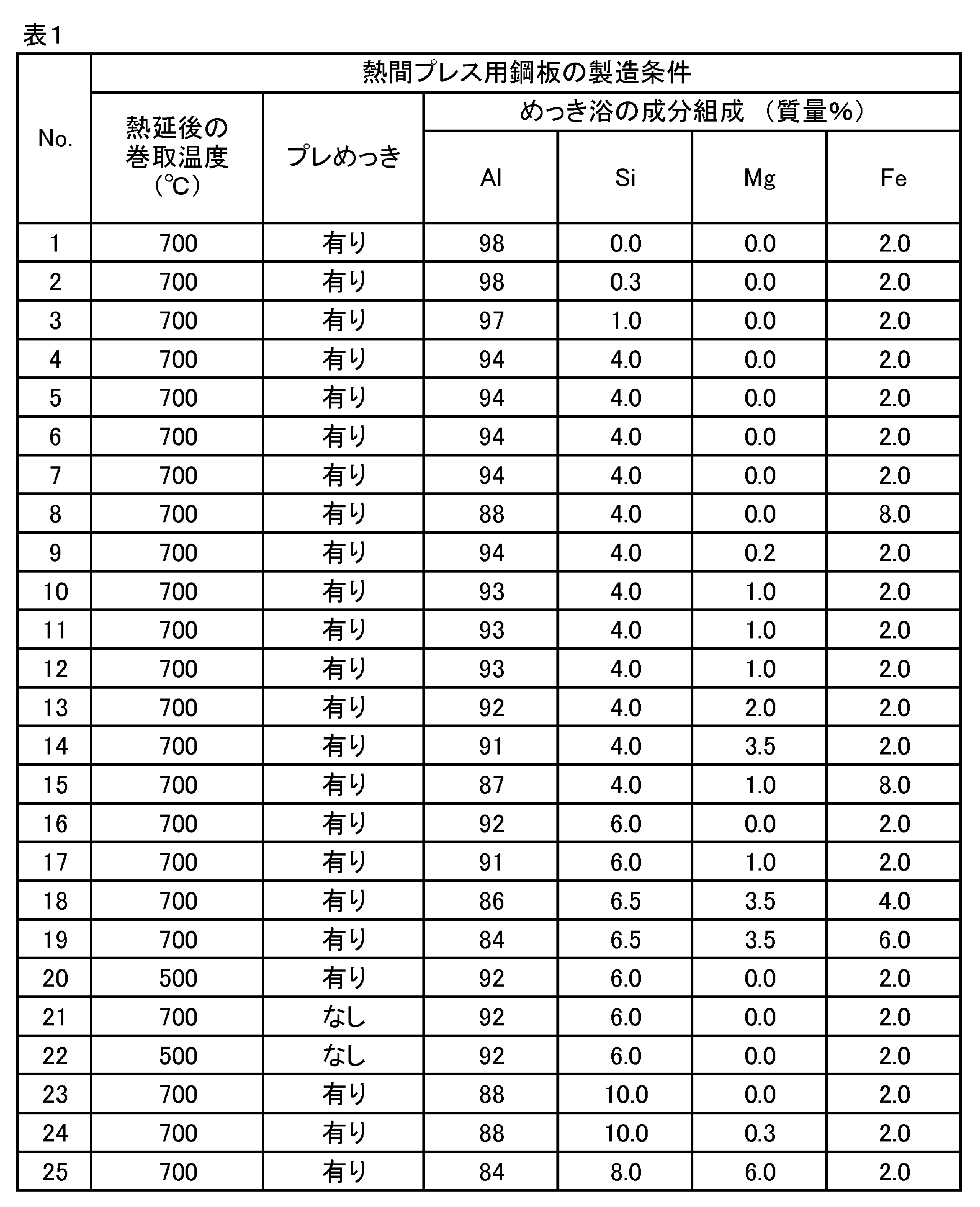
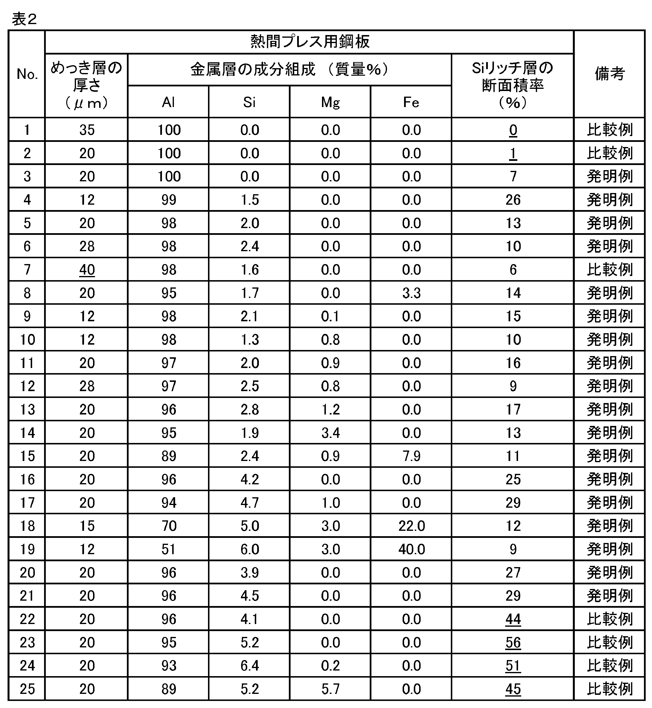
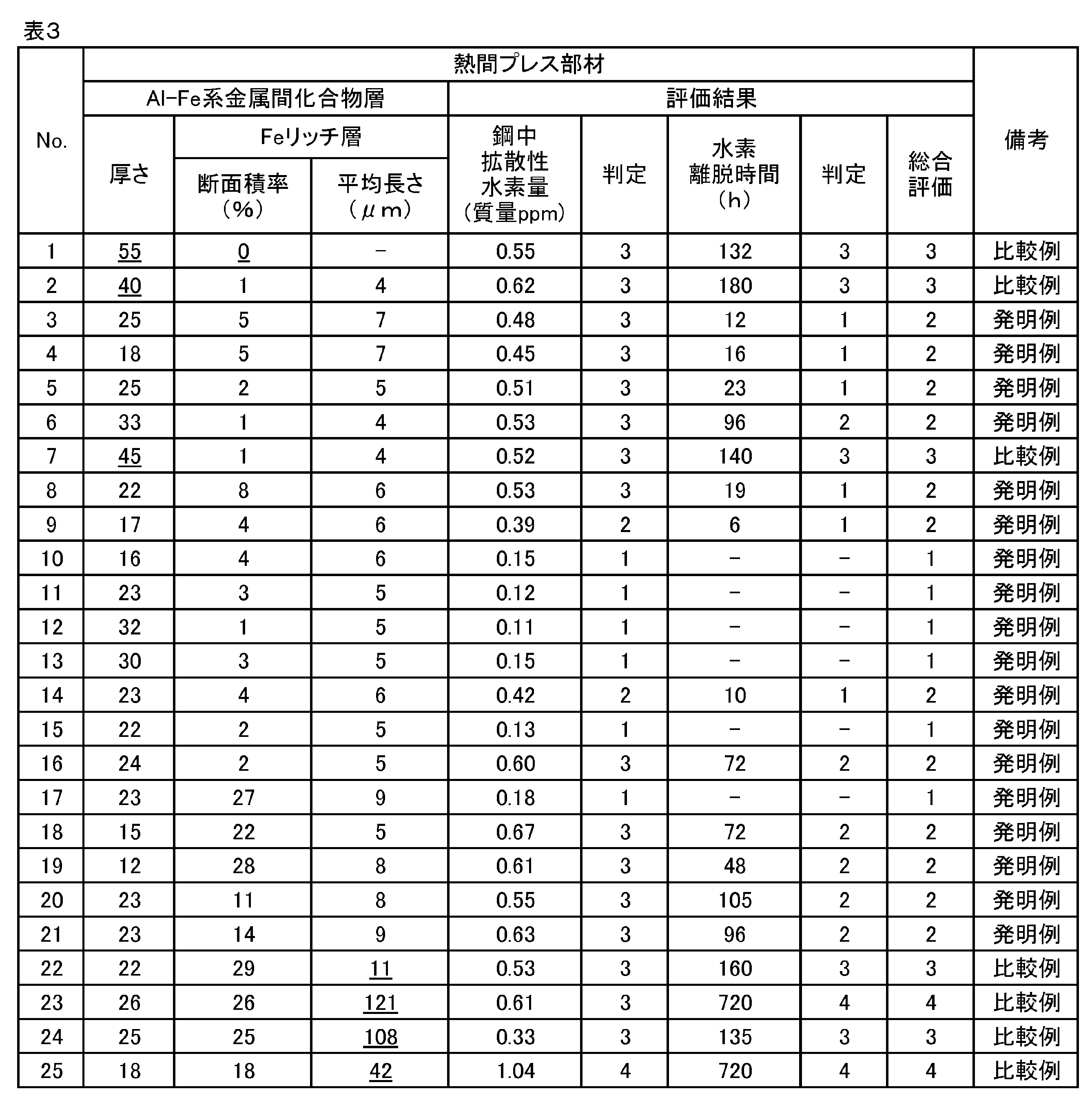
Claims (6)
- 鋼材と、
前記鋼材の少なくとも一方の面に配された、厚さ10~35μmのAl-Fe系金属間化合物層と、
前記Al-Fe系金属間化合物層と前記鋼材との間の界面に配された拡散層とを備え、
前記Al-Fe系金属間化合物層が、Al濃度40質量%以上であるAlリッチ相と、Al濃度40質量%未満であるFeリッチ相とを含み、
前記Feリッチ相の断面における板厚方向と垂直な方向の平均長さが10μm以下である、熱間プレス部材。 - 前記鋼材中の拡散性水素量が0.30質量ppm以下である、請求項1に記載の熱間プレス部材。
- 母材鋼板と、
前記母材鋼板の少なくとも一方の面に配された、厚さ10~35μmのめっき層とを備え、
前記めっき層は、
前記母材鋼板上に配された界面合金層と、
前記界面合金層上に配された、Al含有量が50質量%以上である金属層とを備え、
前記界面合金層が、Si濃度4質量%以上であるSiリッチ相を含み、
前記界面合金層全体に対する前記Siリッチ相の断面積率が5%以上30%以下である、熱間プレス用鋼板。 - 前記金属層が、
Si:0.5~7.0質量%、および
Fe:0~30質量%を含有する、請求項3に記載の熱間プレス用鋼板。 - 前記金属層がさらに、
Mg:0.1~4.0質量%を含有する、請求項4に記載の熱間プレス用鋼板。 - 請求項3~5のいずれか一項に記載の熱間プレス用鋼板を熱間プレスして熱間プレス部材とする、熱間プレス部材の製造方法。
Priority Applications (6)
| Application Number | Priority Date | Filing Date | Title |
|---|---|---|---|
| KR1020247040943A KR20250004381A (ko) | 2022-06-03 | 2023-03-27 | 열간 프레스 부재, 열간 프레스용 강판 및, 열간 프레스 부재의 제조 방법 |
| JP2023540210A JP7568115B2 (ja) | 2022-06-03 | 2023-03-27 | 熱間プレス部材、熱間プレス用鋼板、および熱間プレス部材の製造方法 |
| CN202380043579.7A CN119301293A (zh) | 2022-06-03 | 2023-03-27 | 热压部件、热压用钢板和热压部件的制造方法 |
| US18/859,542 US20250276352A1 (en) | 2022-06-03 | 2023-03-27 | Hot pressed member, steel sheet for hot press forming, and method of producing hot pressed member |
| EP23815541.0A EP4512924A4 (en) | 2022-06-03 | 2023-03-27 | HOT-PRESSED MEMBER, HOT-PRESSING STEEL SHEET AND METHOD FOR PRODUCING HOT-PRESSED MEMBER |
| MX2024014952A MX2024014952A (es) | 2022-06-03 | 2024-12-02 | Miembro prensado en caliente, chapa de acero para conformado por prensado en caliente y metodo de produccion de miembro prensado en caliente |
Applications Claiming Priority (2)
| Application Number | Priority Date | Filing Date | Title |
|---|---|---|---|
| JP2022-091188 | 2022-06-03 | ||
| JP2022091188 | 2022-06-03 |
Publications (1)
| Publication Number | Publication Date |
|---|---|
| WO2023233779A1 true WO2023233779A1 (ja) | 2023-12-07 |
Family
ID=89026110
Family Applications (1)
| Application Number | Title | Priority Date | Filing Date |
|---|---|---|---|
| PCT/JP2023/012271 Ceased WO2023233779A1 (ja) | 2022-06-03 | 2023-03-27 | 熱間プレス部材、熱間プレス用鋼板、および熱間プレス部材の製造方法 |
Country Status (7)
| Country | Link |
|---|---|
| US (1) | US20250276352A1 (ja) |
| EP (1) | EP4512924A4 (ja) |
| JP (1) | JP7568115B2 (ja) |
| KR (1) | KR20250004381A (ja) |
| CN (1) | CN119301293A (ja) |
| MX (1) | MX2024014952A (ja) |
| WO (1) | WO2023233779A1 (ja) |
Cited By (1)
| Publication number | Priority date | Publication date | Assignee | Title |
|---|---|---|---|---|
| JP7726429B1 (ja) * | 2024-03-21 | 2025-08-20 | Jfeスチール株式会社 | 熱間プレス部材および熱間プレス用鋼板 |
Citations (5)
| Publication number | Priority date | Publication date | Assignee | Title |
|---|---|---|---|---|
| WO2012137687A1 (ja) * | 2011-04-01 | 2012-10-11 | 新日本製鐵株式会社 | 塗装後耐食性に優れたホットスタンプ成形された高強度部品およびその製造方法 |
| US20210187583A1 (en) * | 2019-12-20 | 2021-06-24 | Hyundai Steel Company | Hot stamping component and method of manufacturing the same |
| JP2022513132A (ja) * | 2018-11-30 | 2022-02-07 | ポスコ | 耐食性及び耐熱性に優れた熱間成形用アルミニウム-鉄合金めっき鋼板、熱間プレス成形部材及びこれらの製造方法 |
| JP2022513133A (ja) * | 2018-11-30 | 2022-02-07 | ポスコ | 水素遅延破壊特性及びスポット溶接性に優れた熱間プレス用鉄-アルミニウム系めっき鋼板及びその製造方法 |
| WO2022091529A1 (ja) * | 2020-10-27 | 2022-05-05 | Jfeスチール株式会社 | 熱間プレス部材および熱間プレス用鋼板ならびにそれらの製造方法 |
Family Cites Families (4)
| Publication number | Priority date | Publication date | Assignee | Title |
|---|---|---|---|---|
| JP4023710B2 (ja) | 2001-06-25 | 2007-12-19 | 新日本製鐵株式会社 | 耐食性,耐熱性に優れたホットプレス用アルミ系めっき鋼板およびそれを使用した自動車用部材 |
| EP4534706A3 (en) * | 2018-05-31 | 2025-07-23 | POSCO Co., Ltd | Al-fe-alloy plated steel sheet for hot forming, having excellent twb welding characteristics and manufacturing methods therefor |
| MX2021006196A (es) * | 2018-11-30 | 2021-07-16 | Posco | Placa de acero chapada en base a aluminio para prensa caliente que tiene excelente resistencia contra la fractura retardada de hidrógeno y soldabilidad por puntos y método para manufactura de la misma. |
| KR102330812B1 (ko) * | 2020-06-30 | 2021-11-24 | 현대제철 주식회사 | 열간 프레스용 강판 및 이의 제조 방법 |
-
2023
- 2023-03-27 CN CN202380043579.7A patent/CN119301293A/zh active Pending
- 2023-03-27 WO PCT/JP2023/012271 patent/WO2023233779A1/ja not_active Ceased
- 2023-03-27 US US18/859,542 patent/US20250276352A1/en active Pending
- 2023-03-27 EP EP23815541.0A patent/EP4512924A4/en active Pending
- 2023-03-27 KR KR1020247040943A patent/KR20250004381A/ko active Pending
- 2023-03-27 JP JP2023540210A patent/JP7568115B2/ja active Active
-
2024
- 2024-12-02 MX MX2024014952A patent/MX2024014952A/es unknown
Patent Citations (5)
| Publication number | Priority date | Publication date | Assignee | Title |
|---|---|---|---|---|
| WO2012137687A1 (ja) * | 2011-04-01 | 2012-10-11 | 新日本製鐵株式会社 | 塗装後耐食性に優れたホットスタンプ成形された高強度部品およびその製造方法 |
| JP2022513132A (ja) * | 2018-11-30 | 2022-02-07 | ポスコ | 耐食性及び耐熱性に優れた熱間成形用アルミニウム-鉄合金めっき鋼板、熱間プレス成形部材及びこれらの製造方法 |
| JP2022513133A (ja) * | 2018-11-30 | 2022-02-07 | ポスコ | 水素遅延破壊特性及びスポット溶接性に優れた熱間プレス用鉄-アルミニウム系めっき鋼板及びその製造方法 |
| US20210187583A1 (en) * | 2019-12-20 | 2021-06-24 | Hyundai Steel Company | Hot stamping component and method of manufacturing the same |
| WO2022091529A1 (ja) * | 2020-10-27 | 2022-05-05 | Jfeスチール株式会社 | 熱間プレス部材および熱間プレス用鋼板ならびにそれらの製造方法 |
Non-Patent Citations (1)
| Title |
|---|
| See also references of EP4512924A4 * |
Cited By (2)
| Publication number | Priority date | Publication date | Assignee | Title |
|---|---|---|---|---|
| JP7726429B1 (ja) * | 2024-03-21 | 2025-08-20 | Jfeスチール株式会社 | 熱間プレス部材および熱間プレス用鋼板 |
| WO2025197253A1 (ja) * | 2024-03-21 | 2025-09-25 | Jfeスチール株式会社 | 熱間プレス部材および熱間プレス用鋼板 |
Also Published As
| Publication number | Publication date |
|---|---|
| MX2024014952A (es) | 2025-01-09 |
| EP4512924A1 (en) | 2025-02-26 |
| CN119301293A (zh) | 2025-01-10 |
| US20250276352A1 (en) | 2025-09-04 |
| JP7568115B2 (ja) | 2024-10-16 |
| JPWO2023233779A1 (ja) | 2023-12-07 |
| KR20250004381A (ko) | 2025-01-07 |
| EP4512924A4 (en) | 2025-10-22 |
Similar Documents
| Publication | Publication Date | Title |
|---|---|---|
| CN111936650B (zh) | 高强度镀锌钢板、高强度部件和它们的制造方法 | |
| JP5223360B2 (ja) | 成形性に優れた高強度溶融亜鉛めっき鋼板およびその製造方法 | |
| JP4781836B2 (ja) | 耐水素脆性に優れた超高強度鋼板とその製造方法及び超高強度溶融亜鉛めっき鋼板の製造方法並びに超高強度合金化溶融亜鉛めっき鋼板の製造方法 | |
| JP5162836B2 (ja) | 溶接部の耐水素脆性に優れる高強度冷延鋼板及びその製造方法 | |
| JP4589880B2 (ja) | 成形性と穴拡げ性に優れた高強度溶融亜鉛めっき鋼板と高強度合金化溶融亜鉛めっき鋼板及び高強度溶融亜鉛めっき鋼板の製造方法並びに高強度合金化溶融亜鉛めっき鋼板の製造方法 | |
| KR102100746B1 (ko) | 고강도 용융 아연 도금 강판의 제조 방법, 고강도 용융 아연 도금 강판용 열연 강판의 제조 방법, 고강도 용융 아연 도금 강판용 냉연 강판의 제조 방법 및, 고강도 용융 아연 도금 강판 | |
| JP4837604B2 (ja) | 合金化溶融亜鉛めっき鋼板 | |
| KR20010042985A (ko) | 강판, 용융 도금 강판 및 합금화 용융 도금 강판과 이들의제조 방법 | |
| WO2023132350A1 (ja) | ホットスタンプ用鋼板、ホットスタンプ用鋼板の製造方法、及びホットスタンプ成形体 | |
| JP2009270126A (ja) | 冷延鋼板および溶融めっき鋼板ならびに該鋼板の製造方法 | |
| KR20220142518A (ko) | 핫 스탬프 성형체 | |
| KR102904904B1 (ko) | 열간 프레스 부재 및 열간 프레스용 강판 그리고 그것들의 제조 방법 | |
| JPH0913147A (ja) | 成型性及びめっき密着性に優れた高強度合金化溶融亜鉛めっき鋼板およびその製造方法 | |
| KR20220143744A (ko) | 핫 스탬프 성형체 | |
| JP7773087B2 (ja) | ホットスタンプ部材 | |
| WO2019189841A1 (ja) | 高強度亜鉛めっき鋼板、高強度部材およびそれらの製造方法 | |
| WO2023132349A1 (ja) | ホットスタンプ用鋼板、ホットスタンプ用鋼板の製造方法、及びホットスタンプ成形体 | |
| JP7485219B2 (ja) | 熱間プレス部材および熱間プレス用鋼板、ならびにそれらの製造方法 | |
| JP6624352B1 (ja) | 高強度亜鉛めっき鋼板、高強度部材およびそれらの製造方法 | |
| JP7568115B2 (ja) | 熱間プレス部材、熱間プレス用鋼板、および熱間プレス部材の製造方法 | |
| JP4947565B2 (ja) | めっき密着性およびプレス成形性に優れた高強度溶融亜鉛めっき鋼板の製造方法。 | |
| JP2009280859A (ja) | 加工性、めっき密着性、耐食性、および外観品位に優れた合金化溶融亜鉛めっき鋼板 | |
| JP3646538B2 (ja) | 加工性に優れた溶融亜鉛めっき高張力鋼板の製造方法 | |
| JP5092858B2 (ja) | 溶融亜鉛めっき用鋼板及び合金化溶融亜鉛めっき鋼板 | |
| JP3921101B2 (ja) | 形状凍結性に優れた高強度高延性溶融亜鉛めっき鋼板の製造方法 |
Legal Events
| Date | Code | Title | Description |
|---|---|---|---|
| ENP | Entry into the national phase |
Ref document number: 2023540210 Country of ref document: JP Kind code of ref document: A |
|
| 121 | Ep: the epo has been informed by wipo that ep was designated in this application |
Ref document number: 23815541 Country of ref document: EP Kind code of ref document: A1 |
|
| WWE | Wipo information: entry into national phase |
Ref document number: 202417090172 Country of ref document: IN Ref document number: 2023815541 Country of ref document: EP |
|
| ENP | Entry into the national phase |
Ref document number: 2023815541 Country of ref document: EP Effective date: 20241120 |
|
| WWE | Wipo information: entry into national phase |
Ref document number: 2401007809 Country of ref document: TH |
|
| WWE | Wipo information: entry into national phase |
Ref document number: 202380043579.7 Country of ref document: CN |
|
| WWE | Wipo information: entry into national phase |
Ref document number: MX/A/2024/014952 Country of ref document: MX |
|
| ENP | Entry into the national phase |
Ref document number: 20247040943 Country of ref document: KR Kind code of ref document: A |
|
| WWE | Wipo information: entry into national phase |
Ref document number: 1020247040943 Country of ref document: KR |
|
| NENP | Non-entry into the national phase |
Ref country code: DE |
|
| WWP | Wipo information: published in national office |
Ref document number: 202380043579.7 Country of ref document: CN |
|
| WWP | Wipo information: published in national office |
Ref document number: 18859542 Country of ref document: US |