WO2023238424A1 - 検査システム - Google Patents
検査システム Download PDFInfo
- Publication number
- WO2023238424A1 WO2023238424A1 PCT/JP2022/042925 JP2022042925W WO2023238424A1 WO 2023238424 A1 WO2023238424 A1 WO 2023238424A1 JP 2022042925 W JP2022042925 W JP 2022042925W WO 2023238424 A1 WO2023238424 A1 WO 2023238424A1
- Authority
- WO
- WIPO (PCT)
- Prior art keywords
- inspection system
- camera
- wiring cable
- images
- light emitting
- Prior art date
- Legal status (The legal status is an assumption and is not a legal conclusion. Google has not performed a legal analysis and makes no representation as to the accuracy of the status listed.)
- Ceased
Links
Images


Classifications
-
- H—ELECTRICITY
- H04—ELECTRIC COMMUNICATION TECHNIQUE
- H04N—PICTORIAL COMMUNICATION, e.g. TELEVISION
- H04N23/00—Cameras or camera modules comprising electronic image sensors; Control thereof
- H04N23/56—Cameras or camera modules comprising electronic image sensors; Control thereof provided with illuminating means
-
- G—PHYSICS
- G01—MEASURING; TESTING
- G01N—INVESTIGATING OR ANALYSING MATERIALS BY DETERMINING THEIR CHEMICAL OR PHYSICAL PROPERTIES
- G01N21/00—Investigating or analysing materials by the use of optical means, i.e. using sub-millimetre waves, infrared, visible or ultraviolet light
- G01N21/84—Systems specially adapted for particular applications
- G01N21/88—Investigating the presence of flaws or contamination
- G01N21/8806—Specially adapted optical and illumination features
-
- G—PHYSICS
- G01—MEASURING; TESTING
- G01N—INVESTIGATING OR ANALYSING MATERIALS BY DETERMINING THEIR CHEMICAL OR PHYSICAL PROPERTIES
- G01N21/00—Investigating or analysing materials by the use of optical means, i.e. using sub-millimetre waves, infrared, visible or ultraviolet light
- G01N21/84—Systems specially adapted for particular applications
- G01N21/88—Investigating the presence of flaws or contamination
- G01N21/8851—Scan or image signal processing specially adapted therefor, e.g. for scan signal adjustment, for detecting different kinds of defects, for compensating for structures, markings, edges
-
- H—ELECTRICITY
- H04—ELECTRIC COMMUNICATION TECHNIQUE
- H04N—PICTORIAL COMMUNICATION, e.g. TELEVISION
- H04N23/00—Cameras or camera modules comprising electronic image sensors; Control thereof
- H04N23/60—Control of cameras or camera modules
-
- H—ELECTRICITY
- H04—ELECTRIC COMMUNICATION TECHNIQUE
- H04N—PICTORIAL COMMUNICATION, e.g. TELEVISION
- H04N23/00—Cameras or camera modules comprising electronic image sensors; Control thereof
- H04N23/70—Circuitry for compensating brightness variation in the scene
- H04N23/74—Circuitry for compensating brightness variation in the scene by influencing the scene brightness using illuminating means
-
- H—ELECTRICITY
- H04—ELECTRIC COMMUNICATION TECHNIQUE
- H04N—PICTORIAL COMMUNICATION, e.g. TELEVISION
- H04N23/00—Cameras or camera modules comprising electronic image sensors; Control thereof
- H04N23/95—Computational photography systems, e.g. light-field imaging systems
-
- G—PHYSICS
- G01—MEASURING; TESTING
- G01N—INVESTIGATING OR ANALYSING MATERIALS BY DETERMINING THEIR CHEMICAL OR PHYSICAL PROPERTIES
- G01N21/00—Investigating or analysing materials by the use of optical means, i.e. using sub-millimetre waves, infrared, visible or ultraviolet light
- G01N21/84—Systems specially adapted for particular applications
- G01N21/88—Investigating the presence of flaws or contamination
- G01N21/8806—Specially adapted optical and illumination features
- G01N2021/8809—Adjustment for highlighting flaws
-
- G—PHYSICS
- G01—MEASURING; TESTING
- G01N—INVESTIGATING OR ANALYSING MATERIALS BY DETERMINING THEIR CHEMICAL OR PHYSICAL PROPERTIES
- G01N21/00—Investigating or analysing materials by the use of optical means, i.e. using sub-millimetre waves, infrared, visible or ultraviolet light
- G01N21/84—Systems specially adapted for particular applications
- G01N21/88—Investigating the presence of flaws or contamination
- G01N21/8806—Specially adapted optical and illumination features
- G01N2021/8812—Diffuse illumination, e.g. "sky"
- G01N2021/8816—Diffuse illumination, e.g. "sky" by using multiple sources, e.g. LEDs
-
- G—PHYSICS
- G01—MEASURING; TESTING
- G01N—INVESTIGATING OR ANALYSING MATERIALS BY DETERMINING THEIR CHEMICAL OR PHYSICAL PROPERTIES
- G01N21/00—Investigating or analysing materials by the use of optical means, i.e. using sub-millimetre waves, infrared, visible or ultraviolet light
- G01N21/84—Systems specially adapted for particular applications
- G01N21/88—Investigating the presence of flaws or contamination
- G01N21/8806—Specially adapted optical and illumination features
- G01N2021/8838—Stroboscopic illumination; synchronised illumination
-
- G—PHYSICS
- G01—MEASURING; TESTING
- G01N—INVESTIGATING OR ANALYSING MATERIALS BY DETERMINING THEIR CHEMICAL OR PHYSICAL PROPERTIES
- G01N21/00—Investigating or analysing materials by the use of optical means, i.e. using sub-millimetre waves, infrared, visible or ultraviolet light
- G01N21/84—Systems specially adapted for particular applications
- G01N21/88—Investigating the presence of flaws or contamination
- G01N21/8851—Scan or image signal processing specially adapted therefor, e.g. for scan signal adjustment, for detecting different kinds of defects, for compensating for structures, markings, edges
- G01N2021/8887—Scan or image signal processing specially adapted therefor, e.g. for scan signal adjustment, for detecting different kinds of defects, for compensating for structures, markings, edges based on image processing techniques
-
- G—PHYSICS
- G01—MEASURING; TESTING
- G01N—INVESTIGATING OR ANALYSING MATERIALS BY DETERMINING THEIR CHEMICAL OR PHYSICAL PROPERTIES
- G01N21/00—Investigating or analysing materials by the use of optical means, i.e. using sub-millimetre waves, infrared, visible or ultraviolet light
- G01N21/84—Systems specially adapted for particular applications
- G01N21/88—Investigating the presence of flaws or contamination
- G01N21/90—Investigating the presence of flaws or contamination in a container or its contents
-
- Y—GENERAL TAGGING OF NEW TECHNOLOGICAL DEVELOPMENTS; GENERAL TAGGING OF CROSS-SECTIONAL TECHNOLOGIES SPANNING OVER SEVERAL SECTIONS OF THE IPC; TECHNICAL SUBJECTS COVERED BY FORMER USPC CROSS-REFERENCE ART COLLECTIONS [XRACs] AND DIGESTS
- Y02—TECHNOLOGIES OR APPLICATIONS FOR MITIGATION OR ADAPTATION AGAINST CLIMATE CHANGE
- Y02B—CLIMATE CHANGE MITIGATION TECHNOLOGIES RELATED TO BUILDINGS, e.g. HOUSING, HOUSE APPLIANCES OR RELATED END-USER APPLICATIONS
- Y02B20/00—Energy efficient lighting technologies, e.g. halogen lamps or gas discharge lamps
- Y02B20/40—Control techniques providing energy savings, e.g. smart controller or presence detection
Definitions
- the present invention relates to an inspection system that inspects an article by irradiating the article with light and photographing it with a camera.
- the goods are illuminated with an illuminator and photographed with a camera to ensure that no defects or foreign matter are overlooked. It is being said.
- the illuminator receives current from the lighting controller to emit light and illuminate the article.
- the photography period of the camera is controlled by an inspection system control device that controls the entire inspection system, and the captured images are sent to the inspection system control device.
- the illumination period in the illuminator is controlled by the illuminator controller by the camera or by the inspection system control device so as to be synchronized with the imaging period.
- the lighting controller supplies the large current required to illuminate the article to the illuminator, generally, as shown in Patent Document 1, the necessary current is supplied from the AC outlet via the AC power distribution cable. Power is supplied.
- the present invention was made in view of the above circumstances, and its purpose is to provide an inspection system that can simplify wiring.
- an inspection system includes an illuminator that has a plurality of light emitting elements and emits light from the plurality of light emitting elements to illuminate an article to be inspected. , a lighting controller that divides the plurality of light emitting elements into N areas (N is a natural number of 2 or more) and sequentially supplies current to each of the N areas during an illumination period to emit light; and the illumination period.
- a camera for sequentially photographing the article in a photographing period synchronized with the camera; an inspection system control device; a first wiring cable for supplying DC power from the camera to the lighting controller or from the lighting controller to the camera; a second wiring cable that supplies DC power from the system control device to the camera or from the inspection system control device to the lighting controller, and the N images taken by the camera are connected to the inspection system control device.
- a test image is reconstructed within or within the camera by inter-image operations or by inter-image operations and inter-pixel operations.
- the inter-image operation is an operation in which the brightness of one of the N images is selected for each pixel, or a brightness of a plurality of the images is selected from the N and added. or an operation in which the luminances of a plurality of the images are selected from N and averaged.
- the first distribution cable transmits a signal from the camera to the lighting controller for supplying the DC power and controlling the illumination period
- the second distribution cable transmits a signal from the inspection system controller to the lighting controller.
- a signal for supplying the DC power to the camera and controlling the photographing period is transmitted to the camera.
- the first wiring cable transmits a signal for supplying the DC power and controlling the imaging period from the lighting controller to the camera
- the second wiring cable transmits a signal for controlling the inspection system control.
- a signal is transmitted from the device to the lighting controller for supplying the DC power and controlling the lighting period.
- the illuminator has red, green, and blue light emitting elements for each of the N areas, and the lighting controller controls the light emitting elements of a first color among red, green, and blue.
- a current is sequentially supplied to each of the N areas during the illumination period to cause the light to be emitted, and then the light emitting element of a second color other than the first color is supplied with a current during the illumination period of each of the N areas.
- a current is sequentially supplied to emit light, and then a current is sequentially supplied to the light emitting elements of a third color other than the first color and the second color during the illumination period of each of the N areas. It can be made to emit light.
- wiring can be simplified.
- FIG. 1 is a schematic external view showing an inspection system according to an embodiment of the present invention. It is a front view showing an example of the illuminator of the inspection system same as the above. It is a circuit diagram showing an example of the illuminator of the inspection system same as the above.
- FIG. 3 is a waveform diagram that simply shows the timing of illumination and imaging of the inspection system same as the above. It is a block diagram showing an example of the lighting controller of the inspection system same as the above. This is an example of an image taken by the camera of the same inspection system as above, and is a photograph showing the first image among 16 images. This is an example of an image taken by the camera of the same inspection system as above, and is a photograph showing the second image among 16 images.
- FIG. 3 is a schematic external view showing another inspection system according to an embodiment of the present invention. It is a block diagram which shows the example of the illumination controller of the other inspection system same as the above. It is a block diagram which shows the example of the camera of the other inspection system same as the above. It is a block diagram showing an example of an inspection system control device of another inspection system same as the above.
- an inspection system 1 includes an illuminator 2, a lighting controller 3, a camera 4, an inspection system control device 5, a first wiring cable 6, and a second wiring cable 7. ing.
- FIG. 1 shows a state in which the article M is illuminated by the illuminator 2 and photographed by the camera 4.
- a coffee bottle is exemplified as the article M
- the illuminator 2 is placed on the back side of the article M
- the surface (front) that emits light is tilted toward the front
- the camera 4 is arranged on the back side of the article M. is placed above the .
- the inspection system controller 5 is typically located relatively far away.
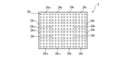
- the illuminator 2 has a plurality of light emitting elements (LEDs, etc.) 20. Light is emitted from the plurality of light emitting elements 20 to illuminate the article M to be inspected.
- the illuminator 2 can be a surface illuminator in which a plurality of light emitting elements 20 are arranged in a planar shape (vertical and horizontal), a line illuminator in which a plurality of light emitting elements 20 are arranged in a line shape, a ring illuminator in which a plurality of light emitting elements 20 are arranged in a ring shape, etc. .
- the illuminator 2 shown in FIG. 1 and FIG. 2, which will be described later, is a surface illuminator, and 192 light emitting elements 20 are arranged in a plane of 12 vertically by 16 horizontally.
- the illuminator 2 is divided into N areas 2A 1 to 2A N as shown in FIG . It is possible to emit light for every natural number (N).
- N natural number
- broken lines indicate the divisions of each area 2A J , N is 16, and each area 2A J has 12 light emitting elements 20, 3 in length x 4 in width.
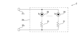
- the illuminator 2 a plurality of light emitting elements 20 are connected in parallel and/or in series. As shown in FIG. 3, the illuminator 2 can be configured such that a current inflow terminal 2IJ and a current outflow terminal 2OJ are provided for each area 2AJ . Note that in FIG. 3, the reference numeral 21 indicates a current limiting resistor. Either one of the current inflow terminal 2IJ and the current outflow terminal 2OJ may be shared between the areas 2A 1 to 2A N.
- the lighting controller 3 divides the plurality of light emitting elements 20 into N areas 2A 1 to 2A N and sequentially supplies a current I J during the illumination period Ta of each area 2A J to emit light.
- the lighting controller 3 operates by being supplied with DC (direct current) power through the first wiring cable 6.
- DC direct current
- the supplied DC power is used as it is, or after being boosted or stepped down.
- the illumination period Ta is synchronized with a photographing period Td, which will be described later, and the illumination period Ta is a signal for controlling the illumination period Ta transmitted by the first wiring cable 6 (a synchronization signal between the photographing period Td and the illumination period Ta). (including SY). (See Figure 4).
- the illumination period Ta is set in advance and can be, for example, 5 milliseconds to 20 milliseconds.
- a PWM pulse current can be used to supply the current.
- the PWM period Tb can be, for example, about 8 microseconds.
- the PWM pulse width Tc is a time width corresponding to a preset dimming gradation.
- the above-mentioned period Tb and pulse width Tc are shown enlarged for easy understanding.
- each part is controlled by the CPU 31 according to a program stored in the program part 32 while using the work memory part 34.
- the interface section 35 is a section to which the first wiring cable 6 is connected.
- the first wiring cable 6 can have a power line 6DC for supplying DC power, a signal line 6SI for controlling the illumination period Ta, and a grounding line 6GND, and interface terminals to which each of them is connected. It can be provided in the section 35.
- the number of signal lines 6SI is one or more.
- the setting section 36 can cause the set value storage section 33 to store values such as the illumination period Ta and pulse width Tc set using the setting dial 36D or the like.
- the setting value storage section 33 can use a nonvolatile memory or the like.
- the illuminator current supply section 37 has an illuminator current outflow terminal 37OJ connected to each of the current inflow terminal 2IJ and the current outflow terminal 2OJ of each area 2AJ of the illuminator 2, and an illuminator current inflow terminal 37IJ connected to each of the current inflow terminal 2IJ and the current outflow terminal 2OJ of each area 2AJ of the illuminator 2. may be provided.
- the lighting controller 3 and the illuminator 2 may be separated and connected by a connecting member 8 (such as a wiring cable), or may be integrated.
- the camera 4 supplies DC power to the lighting controller 3 via the first wiring cable 6.
- the voltage of the DC power is, for example, 3.3V or 5V.
- the camera 4 has a small amount of power that can be supplied externally from it.
- the lighting controller 3 requires less power by sequentially (not all at once ) supplying the current IJ to each area 2AJ of the illuminator 2. Therefore, the camera 4 can supply the necessary power to the lighting controller 3.
- the lighting controller 3 only needs to connect the first wiring cable 6 from the camera 4 without connecting the AC power wiring cable. Thereby, wiring can be simplified.
- the camera 4 sends a signal to control the lighting period Ta including the synchronization signal SY to the lighting controller 3 via the first wiring cable 6.
- the camera 4 sequentially photographs the articles M during a photographing period Td that is synchronized with the illumination period Ta (see FIG. 4).
- the illumination period Ta the illumination period for turning on photographing.
- the signal for turning on photographing is indicated by PH.
- FIG. 6A is a photograph when area 2A 1 of illuminator 2 emits light
- FIG. 6B is a photograph when area 2A 2 of illuminator 2 emits light
- FIG. 6C is a photograph when area 2A 3 of illuminator 2 is emitted.
- FIG. 6D is a photo when area 2A 4 of illuminator 2 emits light
- FIG. 6E is a photo when area 2A 5 of illuminator 2 emits light
- 6F is a photo when area 2A 5 of illuminator 2 emits light.
- a photo when area 2A 6 of illuminator 2 emits light
- Figure 6G is a photo when area 2A 7 of illuminator 2 emits light
- Figure 6H shows a photo when area 2A 8 of illuminator 2 emits light.
- 6I is a photo when area 2A 9 of illuminator 2 emits light
- FIG. 6J is a photo when area 2A 10 of illuminator 2 emits light
- FIG. 6K is an area of illuminator 2.
- 6L is a photo when area 2A 12 of illuminator 2 emits light.
- 6M is a photo when area 2A 13 of illuminator 2 emits light.
- 6N is a photograph when area 2A 14 of illuminator 2 emits light
- FIG. 6O is a photograph when area 2A 15 of illuminator 2 emits light
- FIG. 6P is a photograph when area 2A 16 of illuminator 2 emits light. This is a photo taken when it was radiated.
- the camera 4 operates by being supplied with DC (direct current) power from the second wiring cable 7.
- the supplied DC power is used as it is, or after being boosted or stepped down.
- the camera 4 supplies DC power to the lighting controller 3 via the first wiring cable 6, but the voltage of the DC power supplied to the lighting controller 3 is supplied from the second wiring cable 7.
- the voltage may be the same as the voltage of the supplied DC power, or may be boosted or stepped down.
- the photographing period Td in the camera 4 is controlled by a signal that controls the photographing period Td transmitted by the second wiring cable 7.
- the synchronization signal SY transmitted from the camera 4 to the lighting controller 3 may be generated within the camera 4 in synchronization with the shooting period Td, or may be transmitted via the second wiring cable 7. good.
- the N images (or one inspection image, which will be described later) taken by the camera 4 are transmitted to the inspection system control device 5, which will be described in detail later, via the second wiring cable 7.
- each part is controlled by the CPU 41 according to the program stored in the program part 42 while using the work memory part 43.
- the first interface section 44 can be provided with terminals to which the power line 6DC of the first wiring cable 6, the signal line 6SI of the signal controlling the illumination period Ta, and the ground line 6GND are connected.
- the second interface section 45 is a section to which the second wiring cable 7 is connected.
- the second wiring cable 7 can have a power line 7DC that supplies DC power, a signal line 7SI that transmits signals and images that control the imaging period Td, and a ground line 7GND, each of which is connected
- the second interface section 45 can be provided with a terminal to be used. There are usually a plurality of signal lines 7SI.
- the imaging unit 46 photographs during the above-mentioned photographing period Td using the imaging mechanism 46M. As shown in FIGS. 6A to 6P, images can be captured in monochrome.
- the inspection system control device 5 In the inspection system control device 5, one inspection image is reconstructed from the N images by inter-image arithmetic or by inter-image arithmetic and inter-pixel arithmetic.
- the inspection image is an image that is viewed by an inspector using the inspection system 1.
- an inter-image operation refers to an operation between a plurality of images
- an inter-pixel operation refers to an operation between adjacent pixels forming an image.
- the inter-image calculation can be a calculation in which the brightness of one image is selected from among N images for each pixel. For example, when N is 16, the K-th highest brightness (K is any natural number from 1 to 16) can be selected for each pixel. Then, one inspection image as shown in FIG. 8A, which is equivalent to an image obtained by emitting light from the N areas 2A 1 to 2A N of the illuminator 2 at once, is reconstructed. Note that various inspection images can be obtained depending on the number of K. In FIG. 8A, K is 8.
- the inter-image calculation may be a calculation in which the brightness of a plurality of images is selected from among N images and added for each pixel. For example, if N is 16, the luminance of each pixel goes from the Kth (K is a natural number between 1 and 16) the highest luminance to the Lth (L is a natural number between 2 and 16 that is greater than K). High brightness can be selected and added. Even in this case, one inspection image equivalent to the image obtained by emitting light from the N areas 2A 1 to 2A N of the illuminator 2 all at once is reconstructed. Note that various inspection images can be obtained depending on the numbers of K and L.
- K is set to 1 and L is set to 16 so that the brightness of all (16) images is selected and added at each pixel, one test image as shown in FIG. 8B is reconstructed. .
- the inter-image calculation may be a calculation in which the luminances of a plurality of images are selected from among N images for each pixel and are averaged. For example, if N is 16, the luminance of each pixel goes from the Kth (K is a natural number between 1 and 16) the highest luminance to the Lth (L is a natural number between 2 and 16 that is greater than K). High brightness can be selected and averaged. Even in this case, one inspection image equivalent to the image obtained by emitting light from the N areas 2A 1 to 2A N of the illuminator 2 all at once is reconstructed. Note that various inspection images can be obtained depending on the numbers of K and L.
- K is set to 1 and L is set to 16 so that the brightness of all (16) images is selected and averaged at each pixel, one test image as shown in FIG. 8C is reconstructed. Ru.
- inter-image calculations can also be used to reconstruct one inspection image by combining various inter-pixel calculations.
- the inspection system control device 5 is capable of various processing such as sending an inspection image to a display device and exchanging data with a system outside the inspection system 1.
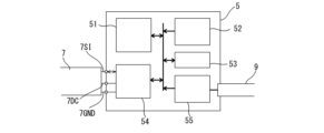
- the inspection system control device 5 has a CPU 51, a program section 52, a work memory section 53, an interface section 54, and a power supply section 55, for example, as shown in FIG. You can do it like this.
- the interface section 54 and the like are controlled by the CPU 51 according to the program stored in the program section 52 while using the work memory section 53.
- the program section 52 includes a program for reconstructing an inspection image.
- the interface section 54 can be provided with terminals to which each of the power line 7DC, signal line 7SI, and ground line 7GND of the second wiring cable 7 is connected.
- the AC power supply wiring cable 9 is connected to the power supply section 55, and DC power for the inspection system control device 5 is generated from the AC power source and supplied to each section within the inspection system control device 5.
- this inspection system 1' includes an illuminator 2, a lighting controller 3', a camera 4', an inspection system control device 5', a first wiring cable 6', and a second wiring cable 7'.
- the illuminator 2 is similar to the above.
- the lighting controller 3', the camera 4', the inspection system control device 5', the first wiring cable 6', and the second wiring cable 7' are connected to the above-mentioned lighting controller 3, camera 4, inspection system control device 5, and first wiring, respectively.
- the inspection system 1' corresponds to the cable 6 and the second distribution cable 7, but in terms of appearance, the way the second distribution cable 7' is wired is similar to that of the second distribution cable 7 in the inspection system 1.
- the method is different. Therefore, the lighting controller 3', the camera 4', the inspection system controller 5', the first wiring cable 6', and the second wiring cable 7' are connected to each other in the following points. 5, the first wiring cable 6, and the second wiring cable 7.
- the lighting controller 3' operates by being supplied with DC (direct current) power through the second wiring cable 7', and is controlled by a signal that controls the lighting period Ta transmitted by the second wiring cable 7'. Furthermore, the lighting controller 3' sends a signal for controlling the photographing period Td, including a synchronization signal SY, to the camera 4' via the first wiring cable 6'. This synchronization signal SY may be generated within the lighting controller 3' in synchronization with the lighting period Ta, or may be transmitted via the second wiring cable 7'. The lighting controller 3' also receives N images (or one inspection image) taken by the camera 4' via the first wiring cable 6', and controls the inspection system via the second wiring cable 7'. It is transmitted to device 5'.
- the lighting controller 3' requires less power by supplying the current IJ to each area 2AJ of the illuminator 2 sequentially (not all at once), so it is possible to connect the AC power supply wiring cable. Instead, it is sufficient to simply connect the second wiring cable 7' from the inspection system control device 5' and connect the first wiring cable 6' toward the camera 4'. Thereby, wiring can be simplified.
- the detailed configuration of the lighting controller 3' may include a first interface section 35A and a second interface section 35B instead of the interface section 35 in the lighting controller 3, as shown in FIG.
- the first interface section 35A is a section to which the first wiring cable 6' is connected.
- the first wiring cable 6' can have a power line 6DC' that supplies DC power, a signal line 6SI' that transmits signals and images that control the imaging period Td, and a ground line 6GND'. Terminals to which each of them is connected can be provided in the first interface section 35A. There are usually a plurality of signal lines 6SI'.
- the second interface part 35B is a part to which the second wiring cable 7' is connected.
- the second wiring cable 7' can include a power line 7DC' for supplying DC power, a signal line 7SI' for transmitting signals and images controlling the illumination period Ta, and a ground line 7GND'. Terminals to which each of them is connected can be provided in the second interface section 35B. There are usually a plurality of signal lines 7SI'.
- the camera 4' operates by being supplied with DC (direct current) power from the first wiring cable 6'.
- the N images (or one inspection image) taken by the camera 4' are transmitted to the inspection system control device 5' via the first distribution cable 6' and the second distribution cable 7', as described above. Ru.
- the detailed configuration of the camera 4' can be such that the camera 4 does not have the second interface part 45 and has an interface part 44' instead of the first interface part 44, as shown in FIG.
- the interface section 44' can be provided with terminals to which each of the power line 6DC', signal line 6SI', and ground line 6GND' of the first wiring cable 6' is connected.
- the detailed configuration of the inspection system control device 5' can include an interface section 54' instead of the interface section 54 in the inspection system control device 5, as shown in FIG.
- the interface section 54' can be provided with terminals to which each of the power line 7DC', signal line 7SI', and ground line 7GND' of the second wiring cable 7' is connected.
- the camera 4 (or 4') can take images in monochrome.
- the illuminator 2 has red, green, and blue light emitting elements 20 in each of N areas 2A 1 to 2A N.
- red, green, and blue light emitting elements 20 current inflow terminals 2I 1 to 2I N and current outflow terminals 2O 1 to 2O N can be provided for each area 2A 1 to 2A N.
- the lighting controller 3 sequentially supplies current to the light emitting elements 20 of the first color among red, green, and blue during the lighting period Ta of each of the N areas 2A 1 to 2A N to produce light. Then, a current is sequentially supplied to the light emitting elements 20 of the second color other than the first color during the illumination period Ta of each of the N areas 2A 1 to 2A N to emit light, and then, A current is sequentially supplied to the light emitting elements of the third color other than the first color and the second color during the illumination period Ta of each of the N areas 2A 1 to 2A N to cause them to emit light.
- the camera 4 sequentially photographs during the photographing period Td in the same manner as described above.
- the inspection system control device 5 or 5'
- one inspection image is reconstructed for red, green, and blue in the same manner as described above, and these three inspection images can be further synthesized. As a result, one color inspection image can be generated.
- the present invention is not limited to what is described in the embodiment, and various design changes can be made within the scope of the matters described in the claims. It is.
- a third wiring cable is provided, and N images (or one inspection image) taken by the camera 4' are transferred to the third wiring cable. It is also possible to transmit the data directly to the inspection system controller 5' via a three-wire cable.
Landscapes
- Engineering & Computer Science (AREA)
- Signal Processing (AREA)
- Multimedia (AREA)
- Life Sciences & Earth Sciences (AREA)
- Analytical Chemistry (AREA)
- Pathology (AREA)
- Physics & Mathematics (AREA)
- Health & Medical Sciences (AREA)
- Immunology (AREA)
- Chemical & Material Sciences (AREA)
- General Physics & Mathematics (AREA)
- Biochemistry (AREA)
- General Health & Medical Sciences (AREA)
- Theoretical Computer Science (AREA)
- Computing Systems (AREA)
- Computer Vision & Pattern Recognition (AREA)
- Investigating Materials By The Use Of Optical Means Adapted For Particular Applications (AREA)
Abstract
Description
2 照明器
20 発光素子
21 抵抗
2AJ(2A1~2AN) エリア
2IJ(2I1~2IN) 電流流入端子
2OJ(2O1~2ON) 電流流出端子
3、3’ 照明コントローラ
31 CPU
32 プログラム部
33 設定値記憶部
34 ワークメモリ部
35 インターフェイス部
35A 第1インターフェイス部
35B 第2インターフェイス部
36 設定部
36D 設定ダイヤル
37 照明器電流供給部
37IJ(37I1~37IN) 照明器電流流入端子
37OJ(37O1~37ON) 照明器電流流出端子
4、4’ カメラ
41 CPU
42 プログラム部
43 ワークメモリ部
44 第1インターフェイス部
44’ インターフェイス部
45 第2インターフェイス部
46 撮像部
46M 撮像機構
5、5’ 検査システム制御装置
51 CPU
52 プログラム部
53 ワークメモリ部
54、54’ インターフェイス部
55 電源部
6、6’ 第1配線ケーブル
6DC、6DC’ 電源線
6SI、6SI’ 信号線
6GND、6GND’ 接地線
7、7’ 第2配線ケーブル
7DC、7DC’ 電源線
7SI、7SI’ 信号線
7GND、7GND’ 接地線
8 コネクト部材
9 AC電源配線ケーブル
IJ(I1~IN) 電流
M 物品
PH 撮影をオンする信号
SY 同期信号
Ta 照明期間
Tb PWMの周期
Tc PWMのパルス幅
Td 撮影期間
Claims (5)
- 複数個の発光素子を有し該複数個の発光素子から光を放射して検査対象である物品を照明する照明器と、
前記複数個の発光素子をN個(Nは2以上の自然数)のエリアに分けて該N個のエリア各々の照明期間に順次電流を供給して光を放射させる照明コントローラと、
前記照明期間と同期する撮影期間で前記物品を順次撮影するカメラと、
検査システム制御装置と、
前記カメラから前記照明コントローラに又は前記照明コントローラから前記カメラにDCの電力を供給する第1配線ケーブルと、
前記検査システム制御装置から前記カメラに又は前記検査システム制御装置から前記照明コントローラにDCの電力を供給する第2配線ケーブルと、
を備え、
前記カメラが撮影したN個の画像は、前記検査システム制御装置の中で又は該カメラの中で、画像間演算により又は画像間演算と画素間演算により1個の検査画像が再構成される検査システム。 - 請求項1に記載の検査システムにおいて、
前記画像間演算は、画素ごとに、N個のうちから1個の前記画像の輝度が選択される演算、又は、N個のうちから複数個の前記画像の輝度が選択されて加算される演算、又は、N個のうちから複数個の前記画像の輝度が選択されて平均化される演算である検査システム。 - 請求項1又は2に記載の検査システムにおいて、
前記第1配線ケーブルは、前記カメラから前記照明コントローラに、前記DCの電力を供給するとともに前記照明期間を制御する信号を伝送し、
前記第2配線ケーブルは、前記検査システム制御装置から前記カメラに、前記DCの電力を供給するとともに前記撮影期間を制御する信号を伝送する検査システム。 - 請求項1又は2に記載の検査システムにおいて、
前記第1配線ケーブルは、前記照明コントローラから前記カメラに、前記DCの電力を供給するとともに前記撮影期間を制御する信号を伝送し、
前記第2配線ケーブルは、前記検査システム制御装置から前記照明コントローラに、前記DCの電力を供給するとともに前記照明期間を制御する信号を伝送する検査システム。 - 請求項1又は2に記載の検査システムにおいて、
前記照明器は、赤色、緑色、青色の発光素子を前記N個のエリア毎に有しており、
前記照明コントローラは、赤色、緑色、青色のうちの第1色の前記発光素子に対して前記N個のエリア各々の前記照明期間に順次電流を供給して光を放射させ、その後、前記第1色以外の第2色の前記発光素子に対して前記N個のエリア各々の前記照明期間に順次電流を供給して光を放射させ、その後、前記第1色及び第2色以外の第3色の前記発光素子に対して前記N個のエリア各々の前記照明期間に順次電流を供給して光を放射させる検査システム。
Priority Applications (4)
| Application Number | Priority Date | Filing Date | Title |
|---|---|---|---|
| US18/858,729 US12273612B1 (en) | 2022-06-08 | 2022-11-18 | Test system |
| EP22945919.3A EP4538685A4 (en) | 2022-06-08 | 2022-11-18 | TESTING SYSTEM |
| CN202280096229.2A CN119278372A (zh) | 2022-06-08 | 2022-11-18 | 检查系统 |
| KR1020247040579A KR20250002791A (ko) | 2022-06-08 | 2022-11-18 | 검사 시스템 |
Applications Claiming Priority (2)
| Application Number | Priority Date | Filing Date | Title |
|---|---|---|---|
| JP2022-093359 | 2022-06-08 | ||
| JP2022093359A JP7185970B1 (ja) | 2022-06-08 | 2022-06-08 | 検査システム |
Publications (1)
| Publication Number | Publication Date |
|---|---|
| WO2023238424A1 true WO2023238424A1 (ja) | 2023-12-14 |
Family
ID=84387538
Family Applications (1)
| Application Number | Title | Priority Date | Filing Date |
|---|---|---|---|
| PCT/JP2022/042925 Ceased WO2023238424A1 (ja) | 2022-06-08 | 2022-11-18 | 検査システム |
Country Status (6)
| Country | Link |
|---|---|
| US (1) | US12273612B1 (ja) |
| EP (1) | EP4538685A4 (ja) |
| JP (1) | JP7185970B1 (ja) |
| KR (1) | KR20250002791A (ja) |
| CN (1) | CN119278372A (ja) |
| WO (1) | WO2023238424A1 (ja) |
Families Citing this family (1)
| Publication number | Priority date | Publication date | Assignee | Title |
|---|---|---|---|---|
| JP2024170792A (ja) * | 2023-05-29 | 2024-12-11 | 株式会社Screenホールディングス | 観察装置、観察方法および基板処理装置 |
Citations (5)
| Publication number | Priority date | Publication date | Assignee | Title |
|---|---|---|---|---|
| JPH1023310A (ja) * | 1996-06-28 | 1998-01-23 | Wilson:Kk | 照明付き拡大画像観察装置及び外観検査システム |
| JP2007003543A (ja) * | 2006-09-19 | 2007-01-11 | Ccs Inc | 画像処理用光照射装置及び画像処理用光照射方法 |
| US20110267451A1 (en) * | 2010-05-03 | 2011-11-03 | United Technologies Corporation | On-the-fly dimensional imaging inspection |
| JP2018017631A (ja) * | 2016-07-28 | 2018-02-01 | シーシーエス株式会社 | 照明制御電源、及び、検査システム |
| JP2018181589A (ja) | 2017-04-12 | 2018-11-15 | 株式会社イマック | 調光電源システム |
Family Cites Families (10)
| Publication number | Priority date | Publication date | Assignee | Title |
|---|---|---|---|---|
| US5519533A (en) * | 1994-03-08 | 1996-05-21 | Sharp Kabushiki Kaisha | Three-dimensional information reproducing apparatus |
| DE10017126C1 (de) * | 2000-04-06 | 2001-06-13 | Krones Ag | Verfahren und Vorrichtung zum optischen Überprüfen transparenter Behälter |
| US7915570B2 (en) * | 2007-08-03 | 2011-03-29 | National Instruments Corporation | Smart camera with an integrated lighting controller |
| JP5833413B2 (ja) * | 2011-11-18 | 2015-12-16 | 株式会社エヌテック | 容器の検査装置 |
| DE102013106894A1 (de) * | 2013-07-01 | 2015-01-08 | Krones Ag | Behälterinspektionsvorrichtung und Behälterinspektionsverfahren zur Inspektion von Behältern |
| JP6520032B2 (ja) * | 2014-09-24 | 2019-05-29 | 富士通株式会社 | 照明装置及び生体認証装置 |
| DE102015106013B4 (de) * | 2015-04-20 | 2024-02-08 | Krones Ag | Behälterinspektionsvorrichtung und Behälterinspektionsverfahren zur Inspektion von Behältern |
| EP4002826B1 (en) * | 2017-02-06 | 2024-06-26 | Intuitive Surgical Operations, Inc. | System and method for extracting multiple feeds from a rolling-shutter sensor |
| EP3537707B1 (de) * | 2018-03-06 | 2021-07-28 | B&R Industrial Automation GmbH | Kamerakern einer smart kamera für die industrielle bildverarbeitung und verfahren zur industriellen bildverarbeitung |
| CN112557408B (zh) * | 2021-02-25 | 2021-07-06 | 中科慧远视觉技术(北京)有限公司 | 频闪阶梯照明缺陷检测系统 |
-
2022
- 2022-06-08 JP JP2022093359A patent/JP7185970B1/ja active Active
- 2022-11-18 CN CN202280096229.2A patent/CN119278372A/zh active Pending
- 2022-11-18 KR KR1020247040579A patent/KR20250002791A/ko active Pending
- 2022-11-18 WO PCT/JP2022/042925 patent/WO2023238424A1/ja not_active Ceased
- 2022-11-18 US US18/858,729 patent/US12273612B1/en active Active
- 2022-11-18 EP EP22945919.3A patent/EP4538685A4/en active Pending
Patent Citations (5)
| Publication number | Priority date | Publication date | Assignee | Title |
|---|---|---|---|---|
| JPH1023310A (ja) * | 1996-06-28 | 1998-01-23 | Wilson:Kk | 照明付き拡大画像観察装置及び外観検査システム |
| JP2007003543A (ja) * | 2006-09-19 | 2007-01-11 | Ccs Inc | 画像処理用光照射装置及び画像処理用光照射方法 |
| US20110267451A1 (en) * | 2010-05-03 | 2011-11-03 | United Technologies Corporation | On-the-fly dimensional imaging inspection |
| JP2018017631A (ja) * | 2016-07-28 | 2018-02-01 | シーシーエス株式会社 | 照明制御電源、及び、検査システム |
| JP2018181589A (ja) | 2017-04-12 | 2018-11-15 | 株式会社イマック | 調光電源システム |
Non-Patent Citations (1)
| Title |
|---|
| See also references of EP4538685A4 |
Also Published As
| Publication number | Publication date |
|---|---|
| CN119278372A (zh) | 2025-01-07 |
| KR20250002791A (ko) | 2025-01-07 |
| US20250119634A1 (en) | 2025-04-10 |
| JP2023180182A (ja) | 2023-12-20 |
| JP7185970B1 (ja) | 2022-12-08 |
| EP4538685A4 (en) | 2025-11-05 |
| EP4538685A1 (en) | 2025-04-16 |
| US12273612B1 (en) | 2025-04-08 |
Similar Documents
| Publication | Publication Date | Title |
|---|---|---|
| CN112557408B (zh) | 频闪阶梯照明缺陷检测系统 | |
| US8988599B2 (en) | Illumination sphere with intelligent LED lighting units in scalable daisy chain with interchangeable filters | |
| US10416086B2 (en) | Image inspection device | |
| JP6917762B2 (ja) | 画像検査装置 | |
| KR101691242B1 (ko) | 다중 모드 이미징 | |
| CN107636528A (zh) | 生产系统内的照相机的控制模块和采用该照相机拍摄图像的方法 | |
| US8942471B2 (en) | Color sequential flash for digital image acquisition | |
| US7551272B2 (en) | Method and an apparatus for simultaneous 2D and 3D optical inspection and acquisition of optical inspection data of an object | |
| WO2023238424A1 (ja) | 検査システム | |
| US20110050984A1 (en) | Method and apparatus for cell analysis | |
| CN110677949A (zh) | 灯具的控制方法和控制系统以及电子设备 | |
| US20170302833A1 (en) | Image projection and capture with simultaneous display of led light | |
| EP1098190A2 (en) | Illumination and image acquistion system | |
| US20170230561A1 (en) | Image projection and capture with adjustment for white point | |
| JP2006058170A (ja) | 目視確認装置および検査システム | |
| CN212845064U (zh) | 一种图纹照明检测系统 | |
| CN102695976A (zh) | 肌肤观察装置 | |
| JP2004126768A (ja) | 画像測定機のカラー画像作成装置およびカラー画像合成方法 | |
| US20160150617A1 (en) | Lighting device for adjusting a light colour separately within severla zones | |
| JP6376648B2 (ja) | 検査用カメラ及び検査システム | |
| JP2006019901A (ja) | 視覚センサ | |
| EP4689618A1 (en) | System and method for illumination of an imaged scene using a programmable light source | |
| JP7562860B2 (ja) | 部品実装機 | |
| CN109064910A (zh) | 一种显示系统及用于操作显示系统的方法 | |
| KR102044355B1 (ko) | 다채널 조명을 이용한 영상 획득장치 및 영상 획득방법 |
Legal Events
| Date | Code | Title | Description |
|---|---|---|---|
| 121 | Ep: the epo has been informed by wipo that ep was designated in this application |
Ref document number: 22945919 Country of ref document: EP Kind code of ref document: A1 |
|
| WWE | Wipo information: entry into national phase |
Ref document number: 18858729 Country of ref document: US |
|
| WWE | Wipo information: entry into national phase |
Ref document number: 202280096229.2 Country of ref document: CN |
|
| WWE | Wipo information: entry into national phase |
Ref document number: 2401007663 Country of ref document: TH |
|
| ENP | Entry into the national phase |
Ref document number: 20247040579 Country of ref document: KR Kind code of ref document: A |
|
| WWE | Wipo information: entry into national phase |
Ref document number: 1020247040579 Country of ref document: KR |
|
| WWP | Wipo information: published in national office |
Ref document number: 202280096229.2 Country of ref document: CN |
|
| WWE | Wipo information: entry into national phase |
Ref document number: 2022945919 Country of ref document: EP |
|
| NENP | Non-entry into the national phase |
Ref country code: DE |
|
| ENP | Entry into the national phase |
Ref document number: 2022945919 Country of ref document: EP Effective date: 20250108 |
|
| WWG | Wipo information: grant in national office |
Ref document number: 18858729 Country of ref document: US |
|
| WWP | Wipo information: published in national office |
Ref document number: 18858729 Country of ref document: US |
|
| WWP | Wipo information: published in national office |
Ref document number: 2022945919 Country of ref document: EP |