WO2023242903A1 - 物体検出装置 - Google Patents
物体検出装置 Download PDFInfo
- Publication number
- WO2023242903A1 WO2023242903A1 PCT/JP2022/023623 JP2022023623W WO2023242903A1 WO 2023242903 A1 WO2023242903 A1 WO 2023242903A1 JP 2022023623 W JP2022023623 W JP 2022023623W WO 2023242903 A1 WO2023242903 A1 WO 2023242903A1
- Authority
- WO
- WIPO (PCT)
- Prior art keywords
- camera
- detected
- data
- detection
- radar
- Prior art date
- Legal status (The legal status is an assumption and is not a legal conclusion. Google has not performed a legal analysis and makes no representation as to the accuracy of the status listed.)
- Ceased
Links
Images


Classifications
-
- G—PHYSICS
- G01—MEASURING; TESTING
- G01S—RADIO DIRECTION-FINDING; RADIO NAVIGATION; DETERMINING DISTANCE OR VELOCITY BY USE OF RADIO WAVES; LOCATING OR PRESENCE-DETECTING BY USE OF THE REFLECTION OR RERADIATION OF RADIO WAVES; ANALOGOUS ARRANGEMENTS USING OTHER WAVES
- G01S13/00—Systems using the reflection or reradiation of radio waves, e.g. radar systems; Analogous systems using reflection or reradiation of waves whose nature or wavelength is irrelevant or unspecified
- G01S13/88—Radar or analogous systems specially adapted for specific applications
- G01S13/93—Radar or analogous systems specially adapted for specific applications for anti-collision purposes
- G01S13/931—Radar or analogous systems specially adapted for specific applications for anti-collision purposes of land vehicles
-
- G—PHYSICS
- G01—MEASURING; TESTING
- G01S—RADIO DIRECTION-FINDING; RADIO NAVIGATION; DETERMINING DISTANCE OR VELOCITY BY USE OF RADIO WAVES; LOCATING OR PRESENCE-DETECTING BY USE OF THE REFLECTION OR RERADIATION OF RADIO WAVES; ANALOGOUS ARRANGEMENTS USING OTHER WAVES
- G01S13/00—Systems using the reflection or reradiation of radio waves, e.g. radar systems; Analogous systems using reflection or reradiation of waves whose nature or wavelength is irrelevant or unspecified
- G01S13/02—Systems using reflection of radio waves, e.g. primary radar systems; Analogous systems
- G01S13/06—Systems determining position data of a target
- G01S13/42—Simultaneous measurement of distance and other co-ordinates
-
- G—PHYSICS
- G01—MEASURING; TESTING
- G01S—RADIO DIRECTION-FINDING; RADIO NAVIGATION; DETERMINING DISTANCE OR VELOCITY BY USE OF RADIO WAVES; LOCATING OR PRESENCE-DETECTING BY USE OF THE REFLECTION OR RERADIATION OF RADIO WAVES; ANALOGOUS ARRANGEMENTS USING OTHER WAVES
- G01S13/00—Systems using the reflection or reradiation of radio waves, e.g. radar systems; Analogous systems using reflection or reradiation of waves whose nature or wavelength is irrelevant or unspecified
- G01S13/02—Systems using reflection of radio waves, e.g. primary radar systems; Analogous systems
- G01S13/50—Systems of measurement based on relative movement of target
- G01S13/58—Velocity or trajectory determination systems; Sense-of-movement determination systems
- G01S13/583—Velocity or trajectory determination systems; Sense-of-movement determination systems using transmission of continuous unmodulated waves, amplitude-, frequency-, or phase-modulated waves and based upon the Doppler effect resulting from movement of targets
- G01S13/584—Velocity or trajectory determination systems; Sense-of-movement determination systems using transmission of continuous unmodulated waves, amplitude-, frequency-, or phase-modulated waves and based upon the Doppler effect resulting from movement of targets adapted for simultaneous range and velocity measurements
-
- G—PHYSICS
- G01—MEASURING; TESTING
- G01S—RADIO DIRECTION-FINDING; RADIO NAVIGATION; DETERMINING DISTANCE OR VELOCITY BY USE OF RADIO WAVES; LOCATING OR PRESENCE-DETECTING BY USE OF THE REFLECTION OR RERADIATION OF RADIO WAVES; ANALOGOUS ARRANGEMENTS USING OTHER WAVES
- G01S13/00—Systems using the reflection or reradiation of radio waves, e.g. radar systems; Analogous systems using reflection or reradiation of waves whose nature or wavelength is irrelevant or unspecified
- G01S13/86—Combinations of radar systems with non-radar systems, e.g. sonar, direction finder
- G01S13/867—Combination of radar systems with cameras
-
- G—PHYSICS
- G06—COMPUTING OR CALCULATING; COUNTING
- G06T—IMAGE DATA PROCESSING OR GENERATION, IN GENERAL
- G06T7/00—Image analysis
- G06T7/70—Determining position or orientation of objects or cameras
- G06T7/73—Determining position or orientation of objects or cameras using feature-based methods
-
- G—PHYSICS
- G06—COMPUTING OR CALCULATING; COUNTING
- G06T—IMAGE DATA PROCESSING OR GENERATION, IN GENERAL
- G06T2207/00—Indexing scheme for image analysis or image enhancement
- G06T2207/10—Image acquisition modality
- G06T2207/10024—Color image
-
- G—PHYSICS
- G06—COMPUTING OR CALCULATING; COUNTING
- G06T—IMAGE DATA PROCESSING OR GENERATION, IN GENERAL
- G06T2207/00—Indexing scheme for image analysis or image enhancement
- G06T2207/10—Image acquisition modality
- G06T2207/10028—Range image; Depth image; 3D point clouds
-
- G—PHYSICS
- G06—COMPUTING OR CALCULATING; COUNTING
- G06T—IMAGE DATA PROCESSING OR GENERATION, IN GENERAL
- G06T2207/00—Indexing scheme for image analysis or image enhancement
- G06T2207/30—Subject of image; Context of image processing
- G06T2207/30248—Vehicle exterior or interior
- G06T2207/30252—Vehicle exterior; Vicinity of vehicle
- G06T2207/30261—Obstacle
Definitions
- the present disclosure relates to an object detection device mounted on a vehicle.
- a vehicle-mounted object detection device has the function of detecting people, structures, etc. that exist in the vehicle usage environment in a short time, controlling the vehicle, and issuing warning notifications, contributing to safe vehicle driving.
- Object detection devices installed in vehicles use various types of sensors such as radar, cameras, LiDAR (Light Detection And Ranging), and ultrasonic sensors, but in recent years, performance has been improved by combining multiple sensors. Fusion-type object detection devices have become widely used.
- Patent Document 1 it is determined whether the detected object is a pedestrian based on the position and speed of the object detected by a radar and object recognition detected by a camera.
- Radar has excellent position and speed detection accuracy, and cameras have excellent object recognition. Therefore, in object detection devices, radar is used for position and speed detection, and cameras are used for object recognition. Common. However, when a detected object such as a person approaches a structure with a high radar reflection intensity such as a utility pole, wall, guardrail, shelf pillar, delineator, or signal, the radar reflected signal of the detected object becomes the radar reflected signal of the structure. If the object is buried, it becomes difficult to detect the object, and the data detected by the radar about the object is lost. In this case, by replacing the radar detection data with the camera detection data, it is possible to maintain the detection accuracy of the fusion-type object detection device.
- a high radar reflection intensity such as a utility pole, wall, guardrail, shelf pillar, delineator, or signal
- cameras such as monocular cameras that are low in manufacturing cost have lower accuracy in detecting the position of objects relative to the vehicle than stereo cameras.
- the position detection accuracy of such cameras deteriorates due to changes in camera characteristics due to temperature and aging, changes in camera posture after installation in a vehicle over time, blurring of camera images due to vibrations that occur when the vehicle is running, and the like.
- the fusion type object detection device has a problem in that when radar detection data disappears, even if it is replaced with camera detection data, high object detection accuracy cannot be obtained.
- the present disclosure has been made in view of the above, and an object of the present disclosure is to obtain an object detection device that can obtain high object detection accuracy when replacing radar detection data with camera detection data. do.
- an object detection device in the present disclosure includes a radar signal processor that performs signal processing on a received signal from a radar to detect the position and speed of an object and a structure; It has a first conversion table that stores the correspondence between the pixel coordinates of the camera and the position of the imaging space with respect to the vehicle, and detects the positions and types of objects and structures based on the image data captured by the camera and the first conversion table.
- the camera image processor performs a first identity determination process, which is identity determination processing, between the position of the object detected by the radar signal processor and the position of the object detected by the camera image processor.
- a second identity determination process is executed to determine whether the position of the structure detected by the camera image processor is the same as the position of the structure detected by the camera image processor, and the first identity determination process result and the second identity determination process result are transmitted to vehicle control. and a fusion processor to be used.
- the camera image processor includes a conversion table updating unit that updates the first conversion table with correspondence data between the position data detected by the radar signal processor and the pixel coordinates of the camera when the second identity determination process is successful.
- the object detection device has the effect of being able to obtain high object detection accuracy when replacing radar detection data with camera detection data.
- Block diagram showing the configuration of an object detection device according to an embodiment Flowchart showing the operation procedure of the object detection device according to the embodiment
- FIG. 1 is a block diagram showing the configuration of an object detection device according to an embodiment.
- the object detection device 100 includes a radar 1 , a camera 2 , a radar signal processor 3 , a camera image processor 4 , and a fusion processor 5 .
- Object detection device 100 is mounted on a vehicle.
- the output of the object detection device 100 is input to a vehicle control unit 30 mounted on the vehicle, and is used for controlling the vehicle.
- the radar 1 emits electromagnetic waves to an object and receives reflected signals from the object.
- the radar signal processor 3 processes the received signal from the radar 1 to detect the position and speed of the object.
- the radar 1 generally uses the FMCW (Frequency Modulated Continuous Wave) method or the FCM (Fast Chirp Modulation) method, and uses high frequency semiconductor components, power supply semiconductor components, substrates, crystal devices, chip components, antennas, etc. It consists of
- the radar signal processor 3 includes a distance detection section 6, a speed detection section 7, a horizontal angle detection section 8, and a radar detection data storage section 9.
- the distance detection unit 6, velocity detection unit 7, and horizontal angle detection unit 8 calculate the distance of objects and structures by performing Fast Fourier Transformation (FFT) in the distance direction, velocity direction, and horizontal angle direction, respectively. , velocity, and horizontal angle.
- FFT Fast Fourier Transformation
- the object represents a desired object to be detected when controlling the vehicle, and includes, for example, a person or a vehicle.
- the structure represents an undesired object that is not necessarily used for vehicle control, and includes, for example, a telephone pole, a wall, a guardrail, a shelf pillar, a delineator, a traffic light, and the like.
- the camera 2 images an object and acquires image data.
- the camera 2 may be a stereo camera or a monocular camera.
- the camera image processor 4 detects the positions and types of objects and structures based on image data captured by the camera 2.
- the image data captured by the camera 2 is also referred to as captured image data.
- the camera 2 is composed of parts such as a lens, a holder, a CMOS (Complementary Metal Oxide Semiconductor) sensor, a power supply semiconductor component, and a crystal device.
- CMOS Complementary Metal Oxide Semiconductor
- the camera image processor 4 an MCU, a CPU, a GPU (Graphics Processing Unit), or the like is used.
- the camera image processor 4 includes an object recognition section 10, a detection frame provision section 11, a detection frame pixel coordinate provision section 12, an object position detection section 13, a camera object detection data storage section 14, a structure recognition section 15, and a structure position detection section. 16, a camera structure detection data storage section 17, a pixel coordinate-position conversion table 18, a conversion table update section 19, a camera internal parameter storage section 25, and a camera external parameter storage section 26.
- the object recognition unit 10 uses feature data obtained by machine learning or deep learning as a database to recognize people, vehicles, etc. from captured image data, and detects the type of object.
- the detection frame adding unit 11 adds a frame to the area of the recognition target on the captured image based on the object recognition result obtained by the object recognition unit 10.
- the assigned frame is called a detection frame.
- the detection frame pixel coordinate assigning unit 12 assigns pixel coordinates of captured image data to the bottom center point of the detection frame.
- the pixel coordinate-position conversion table 18 corresponding to the first conversion table stores correspondence data indicating the correspondence between a plurality of pixel coordinates of the camera 2 and the position of the imaging space of the camera 2 with respect to the vehicle. Assuming that the bottom of an object or the bottom of a structure is located at each pixel coordinate in the imaging space by camera 2, a position (relative position with respect to the vehicle) corresponding to each pixel coordinate is set. There is. Therefore, in the pixel coordinate-position conversion table 18, the position data associated with each pixel coordinate indicates the position data of an object or structure with respect to the vehicle in the imaging space.
- the object position detection unit 13 converts the detection frame portion into object position data by referring to the pixel coordinate-position conversion table 18 based on the pixel coordinates of the detection frame portion obtained by the detection frame pixel coordinate giving unit 12. By doing so, the position of the object relative to the vehicle is detected.
- the camera object detection data storage unit 14 stores the object type obtained by the object recognition unit 10 and the object position obtained by the object position detection unit 13, and outputs them to the subsequent fusion processor 5.
- the structure recognition unit 15 extracts spots with high linearity from the captured image data to identify the vertical component of the vehicle running road surface with respect to the edges of structures such as utility poles, walls, guardrails, shelf pillars, delineators, and traffic lights. Detect. For example, by subjecting the captured image data to Hough transform, only edges with high linearity are detected from the captured image data, and the vertical component of the road surface on which the vehicle is traveling is extracted.
- the structure position detection unit 16 refers to the pixel coordinate-position conversion table 18 for the lowest point closest to the vehicle road surface on the image regarding the vertical component of the straight edge obtained by the structure recognition unit 15. Detects the position of the structure.
- the camera structure detection data storage section 17 stores the structure position and pixel coordinates obtained by the structure position detection section 16, and outputs it to the subsequent fusion processor 5.
- the conversion table update unit 19 updates the fusion structure detection data (position data detected by the radar 1 and pixel coordinate data of the camera 2) about the structure obtained from the fusion structure detection data storage unit 24 of the fusion processor 5. By updating the pixel coordinate-position conversion table 18 based on this, the position detection accuracy of the camera 2 is maintained.
- the camera internal parameter storage unit 25 stores camera internal parameters determined from the lens and CMOS sensor that constitute the camera 2. Camera internal parameters include focal length, image data size, pixel center, lens distortion coefficient, etc. The camera internal parameters are adjusted for each individual product at the time of product shipping inspection and are stored in the camera internal parameter storage section 25.
- the camera external parameter storage unit 26 stores camera external parameters.
- the camera external parameters include the mounting position and attitude angle of the camera 2 after it is mounted on the vehicle.
- the camera external parameters are adjusted for each individual product at the time of product shipping inspection and are stored in the camera external parameter storage section 26.
- Camera internal parameters change depending on temperature and age. Furthermore, camera external parameters vary due to changes in camera posture over time, blurring of images due to vibrations that occur when the vehicle is running, and the like. Therefore, the camera internal parameters stored in the camera internal parameter storage section 25 and the camera external parameters stored in the camera external parameter storage section 26 are used only in the initial state immediately after installation on the vehicle when the object position detection section 13 detects the position. It is referred to when the structure position detection section 16 detects the structure position. After the initial state, the object position detection unit 13 and the structure position detection unit 16 refer to the camera internal parameters stored in the camera internal parameter storage unit 25 and the camera external parameters stored in the camera external parameter storage unit 26. First, the positions of objects and structures are detected by referring to the pixel coordinate-position conversion table 18 that is successively updated by the conversion table updating unit 19.
- the fusion processor 5 includes an object identity determination section 20 , a detection data selection section 21 , a fusion object detection data storage section 22 , a structure identity determination section 23 , a fusion structure detection data storage section 24 , and a nonvolatile memory 27 .
- the object identity determination unit 20 executes identity determination processing between the position of the object detected by the radar 1 and the position of the object detected by the camera 2.
- the identity determination process in the object identity determination section 20 corresponds to the first identity determination process. Through this identity determination process, the position and velocity data detected by the radar 1 and the object recognition data detected by the camera 2 are linked.
- the detection data selection unit 21 succeeds in determining the identity, the detection data selection unit 21 transfers the position and velocity detected by the radar 1 and the object type detected by the camera 2 to the fusion object detection data storage unit 22 .
- the detection data selection unit 21 assumes that the detection data by the radar 1 has disappeared, and stores only the position and object type detected by the camera 2 in the fusion object detection data storage unit 22. Forward.
- the fusion object detection data storage section 22 stores data on these positions, speeds, and object types, transfers the data to the vehicle control section 30, and uses it for vehicle control.
- the structure identity determination unit 23 performs identity determination processing between the position of the structure detected by the radar 1 and the position of the structure detected by the camera 2.
- the identity determination process in the structure identity determination unit 23 corresponds to the second identity determination process. Through this identity determination process, the position data detected by the radar 1 and the pixel coordinates of the structure detected by the camera 2 are linked. If the identity determination is successful, the position detected by the radar 1 and the pixel coordinates of the structure detected by the camera 2 are stored in the fusion structure detection data storage unit 24 as fusion structure detection data.
- the fusion structure detection data storage unit 24 transfers the fusion structure detection data (the position detected by the radar 1 and the pixel coordinates of the structure detected by the camera 2) to the conversion table update unit 19 of the camera image processor 4.
- the nonvolatile memory 27 stores the data in the fusion structure detection data storage section 24 . If the structure does not exist, or if the structure identity determination unit 23 fails in the identity determination process, the data stored in the nonvolatile memory 27 is used to update the pixel coordinate-position conversion table 18.
- the structure identity determination unit 23 performs identity determination processing between the position of the structure detected by the radar 1 and the position of the structure detected by the camera 2, and when the identity determination is successful, the fusion structure is determined.
- the pixel coordinate-position conversion table 18 is sequentially updated in real time using the object detection data (the position of the structure detected by the radar 1 and the pixel coordinates of the structure detected by the camera 2).
- FIG. 2 is a flowchart showing the operation procedure of the object detection device 100 according to the embodiment.
- the operation of the object detection device 100 will be explained using FIG. 2.
- the object detection process is started (step S1), the received data acquired by the radar 1 is input to the radar signal processor 3 (step S2).
- the distance detection section 6, velocity detection section 7, and horizontal angle detection section 8 of the radar signal processor 3 detect the position and velocity of the object (step S3).
- the detected position and speed data are stored in the radar detection data storage section 9 (step S4).
- step S1 when the object detection process is started (step S1), captured image data acquired by the camera 2 is input to the camera image processor 4 (step S5).
- the structure recognition unit 15 of the camera image processor 4 recognizes a structure based on the acquired captured image data (step S6).
- the structure position detection unit 16 detects the position and pixel coordinates of the structure based on the captured image data and the pixel coordinate-position conversion table 18 (step S7).
- the position and pixel coordinates of the structure are stored in the camera structure detection data storage section 17 (step S8).
- FIG. 3 is a diagram showing an example of image data captured by the object detection device 100 according to the embodiment.
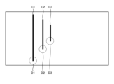
- FIG. 4 is a diagram illustrating an example of data after image processing is performed on image data captured by the object detection device 100 according to the embodiment.
- 3 and 4 show image data of a field where utility poles A1, A2, and A3 are present as an example of structures on the road surface B1.
- utility poles A1, A2, and A3 which are structures, edges with high linearity are detected from the image data, and then a vertical component of the road surface B1 is detected.
- An example of an edge detection method is a method of performing Hough transform on image data. It is possible to detect only highly linear edges from image data after Hough transform.
- FIG. 4 shows an image of image data obtained by extracting only the vertical components C1, C2, and C3 of the road surface B1 after Hough transformation.
- the position of the structure is detected by extracting the pixel coordinates of points D1, D2, and D3 closest to the road surface B1 on the image and referring to the pixel coordinate-position conversion table 18. be able to.
- the object recognition unit 10 of the camera image processor 4 recognizes the object based on the captured image data acquired in step S5 (step S13).
- the object recognition unit 10 uses feature data obtained through machine learning and deep learning as a database to recognize people, vehicles, etc., and detect object types.
- the detection frame assigning unit 11 frames the recognition object, and the detecting frame pixel coordinate assigning unit 12 assigns pixel coordinates to the center of the bottom of the frame (step S14).
- the structure identity determination unit 23 of the fusion processor 5 executes identity determination processing between the position data obtained by the radar 1 obtained in step S4 and the position data of the structure determined by the camera 2 (step S9). Through this identity determination process, the position data detected by the radar 1 and the pixel coordinates of the structure detected by the camera 2 are linked. If the structure identity determination unit 23 succeeds in identity determination in the identity determination process (step S10: Yes), the structure identity determination unit 23 stores the position data of the structure detected by the radar 1 and the pixels of the camera 2 in the fusion structure detection data storage unit 24. Fusion structure detection data including coordinate data is stored (step S11).
- the fusion structure detection data including the position data of the structure detected by the radar 1 and the pixel coordinate data of the camera 2 stored in the fusion structure detection data storage unit 24 is sent to the conversion table update unit 19 of the camera image processor 4. be transferred.
- the conversion table update unit 19 updates the pixel coordinate-position conversion table 18 using the transferred fusion structure detection data (position data of the structure detected by the radar 1 and pixel coordinate data of the camera 2) (step S12). .
- the structure identity determination unit 23 refers to the nonvolatile memory 27 and stores past fusion structure detection data (structures) in the nonvolatile memory 27. position data and pixel coordinate data of camera 2) exists (step S25). If past fusion structure detection data exists (step S25: Yes), for example, the latest fusion structure detection data of the past fusion structure detection data is stored in the conversion table updating unit 19 of the camera image processor 4. be transferred. The conversion table update unit 19 updates the pixel coordinate-position conversion table 18 using the transferred past fusion structure detection data (step S12). If past fusion structure detection data does not exist (step S25: No), the process moves to step S15 without updating the pixel coordinate-position conversion table 18.
- step S15 the object position detection unit 13 of the camera image processor 4 uses the pixel coordinates of the center of the bottom of the frame corresponding to the recognized object and the pixel coordinate-position conversion table 18 given in step S14. , detect the position of the recognized object.
- the camera image processor 4 can detect the position of the object with high accuracy.
- the position of the detected object and the type of object are stored in the camera object detection data storage section 14 (step S16).
- the object identity determination unit 20 of the fusion processor 5 performs identity determination processing between the detected position by the radar 1 acquired in step S4 and the detected position by the camera 2 acquired in step S16 (step S17). Through this identity determination process, the position and velocity data detected by the radar 1 and the object recognition data detected by the camera 2 are linked. If the identity determination fails (step S18: No), the detection data selection unit 21 outputs the position data and object type detected by the camera 2 to the fusion object detection data storage unit 22 (step S19). The fusion object detection data storage unit 22 stores input position data and object type detected by the camera 2.
- the detection data selection unit 21 stores the position and velocity data detected by the radar 1 and the position data and object type detected by the camera 2 in the fusion object detection data storage unit. 22 (step S20).
- the fusion object detection data storage unit 22 stores the input position and speed data detected by the radar 1, position data and object type detected by the camera 2 (step S21).
- the data on the position, speed, and object type of the object stored in the fusion object detection data storage section 22 is output to the vehicle control section 30 (step S22).
- the vehicle control unit 30 uses the data on the position, speed, and object type of the object acquired in step S22 for vehicle control (step S23). With this, the object detection process ends. Thereafter, the object detection process is transferred to the next frame (step S24), and the same process is repeatedly executed from step S1.
- the radar signal processor 3 and the position of the structure detected by the camera image processor 4 are successfully determined to be the same, the radar signal processor
- the pixel coordinate-position conversion table 18 is sequentially updated in real time with the correspondence data between the position data detected in step 3 and the pixel coordinates of the camera 2. Therefore, the accuracy of position detection by the camera 2 can be improved to the accuracy of position detection by the radar 1.
- the position data of the object detected by the camera image processor 4 is used for vehicle control
- the position data of the object detected by the radar signal processor 3 is used for vehicle control. Control is being carried out to replace lost data from radar 1 with detection data from camera 2, so that position data is not used for vehicle control. equipment can be provided.
- the detection data of structures with high radar reflection intensity is used to update the pixel coordinates-position conversion table 18, structures can be detected by the radar 1 and camera 2, respectively, and the fusion processor 5 can detect the structures. It becomes possible to determine the same accuracy.
Landscapes
- Engineering & Computer Science (AREA)
- Radar, Positioning & Navigation (AREA)
- Remote Sensing (AREA)
- Physics & Mathematics (AREA)
- General Physics & Mathematics (AREA)
- Computer Networks & Wireless Communication (AREA)
- Computer Vision & Pattern Recognition (AREA)
- Theoretical Computer Science (AREA)
- Electromagnetism (AREA)
- Radar Systems Or Details Thereof (AREA)
- Traffic Control Systems (AREA)
- Image Analysis (AREA)
Abstract
Description
図1は、実施の形態にかかる物体検出装置の構成を示すブロック図である。物体検出装置100は、レーダ1と、カメラ2と、レーダ信号処理器3と、カメラ画像処理器4と、フュージョン処理器5と、を備える。物体検出装置100は、車両に搭載される。物体検出装置100の出力は、車両に搭載される車両制御部30に入力され、車両の制御に用いられる。
Claims (2)
- レーダからの受信信号を信号処理して、物体および構造物の位置および速度を検出するレーダ信号処理器と、
カメラの画素座標と前記カメラによる撮像空間の車両に対する位置との対応が記憶される第1変換テーブルを有し、前記カメラの撮像画像データおよび前記第1変換テーブルに基づき前記物体および前記構造物の位置および種類を検出するカメラ画像処理器と、
前記レーダ信号処理器で検出した前記物体の位置と前記カメラ画像処理器で検出した前記物体の位置との同一判定処理である第1同一判定処理を実行し、前記レーダ信号処理器で検出した前記構造物の位置と前記カメラ画像処理器で検出した前記構造物の位置との同一判定処理である第2同一判定処理を実行し、前記第1同一判定処理の結果および前記第2同一判定処理の結果を車両制御に用いるフュージョン処理器と、
を備え、
前記カメラ画像処理器は、
前記第2同一判定処理に成功したときの前記レーダ信号処理器で検出された位置データと前記カメラの画素座標との対応データで前記第1変換テーブルを更新する変換テーブル更新部、
を備えることを特徴とする物体検出装置。 - 前記フュージョン処理器は、前記第1同一判定処理での同一判定に失敗した場合、前記カメラ画像処理器によって検出された前記物体の位置データを車両制御に用い、前記レーダ信号処理器で検出された位置データを車両制御に用いない
ことを特徴とする請求項1に記載の物体検出装置。
Priority Applications (3)
| Application Number | Priority Date | Filing Date | Title |
|---|---|---|---|
| EP22946723.8A EP4538744A4 (en) | 2022-06-13 | 2022-06-13 | OBJECT DETECTION DEVICE |
| JP2024527908A JP7531759B2 (ja) | 2022-06-13 | 2022-06-13 | 物体検出装置 |
| PCT/JP2022/023623 WO2023242903A1 (ja) | 2022-06-13 | 2022-06-13 | 物体検出装置 |
Applications Claiming Priority (1)
| Application Number | Priority Date | Filing Date | Title |
|---|---|---|---|
| PCT/JP2022/023623 WO2023242903A1 (ja) | 2022-06-13 | 2022-06-13 | 物体検出装置 |
Publications (1)
| Publication Number | Publication Date |
|---|---|
| WO2023242903A1 true WO2023242903A1 (ja) | 2023-12-21 |
Family
ID=89192589
Family Applications (1)
| Application Number | Title | Priority Date | Filing Date |
|---|---|---|---|
| PCT/JP2022/023623 Ceased WO2023242903A1 (ja) | 2022-06-13 | 2022-06-13 | 物体検出装置 |
Country Status (3)
| Country | Link |
|---|---|
| EP (1) | EP4538744A4 (ja) |
| JP (1) | JP7531759B2 (ja) |
| WO (1) | WO2023242903A1 (ja) |
Cited By (2)
| Publication number | Priority date | Publication date | Assignee | Title |
|---|---|---|---|---|
| JP7566217B1 (ja) * | 2024-01-26 | 2024-10-11 | 三菱電機株式会社 | 物体検出装置及び物体検出方法 |
| JP7734883B1 (ja) * | 2024-11-28 | 2025-09-05 | 三菱電機株式会社 | 物体検出装置 |
Citations (8)
| Publication number | Priority date | Publication date | Assignee | Title |
|---|---|---|---|---|
| WO2010119860A1 (ja) | 2009-04-14 | 2010-10-21 | 日立オートモティブシステムズ株式会社 | 車両用外界認識装置及びそれを用いた車両システム |
| WO2012172870A1 (ja) * | 2011-06-14 | 2012-12-20 | 日産自動車株式会社 | 距離計測装置及び環境地図生成装置 |
| JP2018014583A (ja) * | 2016-07-20 | 2018-01-25 | クラリオン株式会社 | 画像処理装置 |
| US20190120955A1 (en) * | 2017-10-20 | 2019-04-25 | Texas Instruments Incorporated | System and method for camera radar fusion |
| JP2019132795A (ja) * | 2018-02-02 | 2019-08-08 | マクセル株式会社 | 距離算出装置および距離算出方法 |
| US20190251371A1 (en) * | 2018-02-13 | 2019-08-15 | Ford Global Technologies, Llc | Methods and apparatus to facilitate environmental visibility determination |
| JP2019197418A (ja) * | 2018-05-10 | 2019-11-14 | 三菱電機株式会社 | 障害物検知装置 |
| JP2020004293A (ja) * | 2018-06-29 | 2020-01-09 | 日立オートモティブシステムズ株式会社 | 車載電子制御装置 |
Family Cites Families (4)
| Publication number | Priority date | Publication date | Assignee | Title |
|---|---|---|---|---|
| DE102004058251A1 (de) * | 2004-12-03 | 2006-06-08 | Valeo Schalter Und Sensoren Gmbh | Verfahren zur Verarbeitung von Entfernungsdaten |
| US9052393B2 (en) * | 2013-01-18 | 2015-06-09 | Caterpillar Inc. | Object recognition system having radar and camera input |
| US9167214B2 (en) * | 2013-01-18 | 2015-10-20 | Caterpillar Inc. | Image processing system using unified images |
| CN114078326B (zh) * | 2020-08-19 | 2023-04-07 | 北京万集科技股份有限公司 | 碰撞检测方法、装置、视觉传感器和存储介质 |
-
2022
- 2022-06-13 JP JP2024527908A patent/JP7531759B2/ja active Active
- 2022-06-13 WO PCT/JP2022/023623 patent/WO2023242903A1/ja not_active Ceased
- 2022-06-13 EP EP22946723.8A patent/EP4538744A4/en not_active Withdrawn
Patent Citations (8)
| Publication number | Priority date | Publication date | Assignee | Title |
|---|---|---|---|---|
| WO2010119860A1 (ja) | 2009-04-14 | 2010-10-21 | 日立オートモティブシステムズ株式会社 | 車両用外界認識装置及びそれを用いた車両システム |
| WO2012172870A1 (ja) * | 2011-06-14 | 2012-12-20 | 日産自動車株式会社 | 距離計測装置及び環境地図生成装置 |
| JP2018014583A (ja) * | 2016-07-20 | 2018-01-25 | クラリオン株式会社 | 画像処理装置 |
| US20190120955A1 (en) * | 2017-10-20 | 2019-04-25 | Texas Instruments Incorporated | System and method for camera radar fusion |
| JP2019132795A (ja) * | 2018-02-02 | 2019-08-08 | マクセル株式会社 | 距離算出装置および距離算出方法 |
| US20190251371A1 (en) * | 2018-02-13 | 2019-08-15 | Ford Global Technologies, Llc | Methods and apparatus to facilitate environmental visibility determination |
| JP2019197418A (ja) * | 2018-05-10 | 2019-11-14 | 三菱電機株式会社 | 障害物検知装置 |
| JP2020004293A (ja) * | 2018-06-29 | 2020-01-09 | 日立オートモティブシステムズ株式会社 | 車載電子制御装置 |
Non-Patent Citations (1)
| Title |
|---|
| See also references of EP4538744A4 |
Cited By (3)
| Publication number | Priority date | Publication date | Assignee | Title |
|---|---|---|---|---|
| JP7566217B1 (ja) * | 2024-01-26 | 2024-10-11 | 三菱電機株式会社 | 物体検出装置及び物体検出方法 |
| WO2025158678A1 (ja) * | 2024-01-26 | 2025-07-31 | 三菱電機株式会社 | 物体検出装置及び物体検出方法 |
| JP7734883B1 (ja) * | 2024-11-28 | 2025-09-05 | 三菱電機株式会社 | 物体検出装置 |
Also Published As
| Publication number | Publication date |
|---|---|
| JP7531759B2 (ja) | 2024-08-09 |
| EP4538744A4 (en) | 2025-07-16 |
| JPWO2023242903A1 (ja) | 2023-12-21 |
| EP4538744A1 (en) | 2025-04-16 |
Similar Documents
| Publication | Publication Date | Title |
|---|---|---|
| US6670912B2 (en) | Method for detecting stationary object located above road | |
| CN102414715B (zh) | 物体检测装置 | |
| US10353053B2 (en) | Object detection using radar and machine learning | |
| JP3822515B2 (ja) | 障害物検知装置及びその方法 | |
| US10908257B2 (en) | Signal processing apparatus, signal processing method, and program | |
| JP4337929B2 (ja) | 移動状態推定装置 | |
| JP6202367B2 (ja) | 画像処理装置、距離測定装置、移動体機器制御システム、移動体及び画像処理用プログラム | |
| JP3515926B2 (ja) | 車両の周辺監視装置 | |
| JP6450294B2 (ja) | 物体検出装置、物体検出方法、及びプログラム | |
| JP6458651B2 (ja) | 路面標示検出装置及び路面標示検出方法 | |
| JP2002352225A (ja) | 障害物検出装置及びその方法 | |
| US20190065878A1 (en) | Fusion of radar and vision sensor systems | |
| US10846546B2 (en) | Traffic signal recognition device | |
| JP2002298298A (ja) | 車両の周辺監視装置 | |
| JP2005310140A (ja) | オブジェクトの認識及び/又は追跡方法 | |
| KR20200071960A (ko) | 카메라 및 라이다 센서 융합을 이용한 객체 검출 방법 및 그를 위한 장치 | |
| WO2016021606A1 (ja) | 複数の物体検出手段を用いた物体認識装置 | |
| JP2001169310A (ja) | 距離検出装置 | |
| JP4052291B2 (ja) | 車両用画像処理装置 | |
| WO2023242903A1 (ja) | 物体検出装置 | |
| JP4753765B2 (ja) | 障害物認識方法 | |
| JP2001076128A (ja) | 障害物検出装置及び方法 | |
| JP2009075124A (ja) | 距離検出装置 | |
| JP2001018738A (ja) | 車両の周辺監視装置 | |
| US10249056B2 (en) | Vehicle position estimation system |
Legal Events
| Date | Code | Title | Description |
|---|---|---|---|
| 121 | Ep: the epo has been informed by wipo that ep was designated in this application |
Ref document number: 22946723 Country of ref document: EP Kind code of ref document: A1 |
|
| WWE | Wipo information: entry into national phase |
Ref document number: 2024527908 Country of ref document: JP |
|
| WWE | Wipo information: entry into national phase |
Ref document number: 18866205 Country of ref document: US |
|
| WWE | Wipo information: entry into national phase |
Ref document number: 2022946723 Country of ref document: EP |
|
| NENP | Non-entry into the national phase |
Ref country code: DE |
|
| ENP | Entry into the national phase |
Ref document number: 2022946723 Country of ref document: EP Effective date: 20250113 |
|
| WWP | Wipo information: published in national office |
Ref document number: 2022946723 Country of ref document: EP |
|
| WWW | Wipo information: withdrawn in national office |
Ref document number: 2022946723 Country of ref document: EP |