WO2023276077A1 - 手術器具 - Google Patents
手術器具 Download PDFInfo
- Publication number
- WO2023276077A1 WO2023276077A1 PCT/JP2021/024855 JP2021024855W WO2023276077A1 WO 2023276077 A1 WO2023276077 A1 WO 2023276077A1 JP 2021024855 W JP2021024855 W JP 2021024855W WO 2023276077 A1 WO2023276077 A1 WO 2023276077A1
- Authority
- WO
- WIPO (PCT)
- Prior art keywords
- pulley
- opening
- closing
- jaw
- blade portion
- Prior art date
- Legal status (The legal status is an assumption and is not a legal conclusion. Google has not performed a legal analysis and makes no representation as to the accuracy of the status listed.)
- Ceased
Links
Images


Classifications
-
- A—HUMAN NECESSITIES
- A61—MEDICAL OR VETERINARY SCIENCE; HYGIENE
- A61B—DIAGNOSIS; SURGERY; IDENTIFICATION
- A61B17/00—Surgical instruments, devices or methods
- A61B17/32—Surgical cutting instruments
- A61B17/3201—Scissors
-
- A—HUMAN NECESSITIES
- A61—MEDICAL OR VETERINARY SCIENCE; HYGIENE
- A61B—DIAGNOSIS; SURGERY; IDENTIFICATION
- A61B34/00—Computer-aided surgery; Manipulators or robots specially adapted for use in surgery
- A61B34/30—Surgical robots
-
- A—HUMAN NECESSITIES
- A61—MEDICAL OR VETERINARY SCIENCE; HYGIENE
- A61B—DIAGNOSIS; SURGERY; IDENTIFICATION
- A61B34/00—Computer-aided surgery; Manipulators or robots specially adapted for use in surgery
- A61B34/70—Manipulators specially adapted for use in surgery
- A61B34/71—Manipulators operated by drive cable mechanisms
-
- A—HUMAN NECESSITIES
- A61—MEDICAL OR VETERINARY SCIENCE; HYGIENE
- A61B—DIAGNOSIS; SURGERY; IDENTIFICATION
- A61B17/00—Surgical instruments, devices or methods
- A61B2017/00982—General structural features
-
- A—HUMAN NECESSITIES
- A61—MEDICAL OR VETERINARY SCIENCE; HYGIENE
- A61B—DIAGNOSIS; SURGERY; IDENTIFICATION
- A61B17/00—Surgical instruments, devices or methods
- A61B17/32—Surgical cutting instruments
- A61B17/320068—Surgical cutting instruments using mechanical vibrations, e.g. ultrasonic
- A61B2017/320072—Working tips with special features, e.g. extending parts
- A61B2017/320074—Working tips with special features, e.g. extending parts blade
-
- A—HUMAN NECESSITIES
- A61—MEDICAL OR VETERINARY SCIENCE; HYGIENE
- A61B—DIAGNOSIS; SURGERY; IDENTIFICATION
- A61B34/00—Computer-aided surgery; Manipulators or robots specially adapted for use in surgery
- A61B34/30—Surgical robots
- A61B2034/302—Surgical robots specifically adapted for manipulations within body cavities, e.g. within abdominal or thoracic cavities
-
- A—HUMAN NECESSITIES
- A61—MEDICAL OR VETERINARY SCIENCE; HYGIENE
- A61B—DIAGNOSIS; SURGERY; IDENTIFICATION
- A61B34/00—Computer-aided surgery; Manipulators or robots specially adapted for use in surgery
- A61B34/30—Surgical robots
- A61B2034/305—Details of wrist mechanisms at distal ends of robotic arms
Definitions
- the present invention relates to the technical field of surgical instruments attached to surgical robot arms.
- Surgical instruments include, for example, a base body attached to a robot arm and an end effector provided at the distal end.
- end effectors include scissors, forceps, hooks, high-frequency knives, clampers, staplers, and the like. used (see, for example, Patent Document 1).
- Surgery using a surgical robot as described above is generally performed by a surgeon (doctor) remotely operating a surgical robot installed in an operating room using a master-slave system.
- a surgical instrument is inserted into the patient's body through a port formed in a body cavity, and the surgical instrument is operated to treat an affected area, observe the affected area, and the like.
- the surgical instrument described in Patent Document 1 uses scissors for resecting an affected area as an end effector, and the end effector has a first jaw and a second jaw.
- the first jaw is provided with a first pulley and the second jaw is provided with a second pulley, one end of a first wire is connected to the first pulley, and the second pulley is One end of the second wire is connected.
- the first and second jaws are in contact with each other to ensure good sharpness against shear resistance during the closing operation of the first and second jaws.
- it is desirable to apply a force in the direction if excessive force is applied to the first jaw and the second jaw in a direction in which they are in contact with each other, the first jaw and the second jaw may not smoothly move. opening operation may be hindered.
- the surgical instrument of the present invention aims to ensure a stable and highly accurate operating state of the end effector.
- a surgical instrument is a surgical instrument attached to a surgical robot arm, comprising a base body detachable from the robot arm, a support body connected to the base body, An end effector having a first jaw and a second jaw, which are rotatably supported by the support body about a rotation shaft, is provided, and the first jaw is connected to a first opening wire.
- a first closing pulley to which a first opening pulley and a first closing wire are connected; a second opening pulley to which an opening wire is connected; a second closing pulley to which a second closing wire is connected; and a second blade portion operated in the opening and closing direction,
- One opening pulley and the first closing pulley are supported by the rotating shaft in a state separated in the axial direction of the rotating shaft, and the second opening pulley and the second closing pulley are supported. are separated from each other in the axial direction of the rotating shaft, and the first blade portion and the second blade portion are connected to the first opening wire and the second opening wire, respectively.
- the first closing wire and the second closing wire are pulled so as to move toward each other in the opening direction by pulling the first closing wire and the second closing wire.
- the first opening pulley is located closer to the first blade portion than the second blade portion with respect to the first closing pulley in the direction orthogonal to the direction perpendicular to the opening and closing direction.
- Two opening pulleys are located closer to the second blade than the first blade with respect to the second closing pulley.
- a force is applied to the first blade portion and the second blade portion in a direction perpendicular to the opening/closing direction and in a direction in which they are in contact with each other due to the moment generated when the first jaw and the second jaw are opened.
- a force is applied to the first blade portion and the second blade portion in a direction perpendicular to the opening/closing direction in directions away from each other due to the moment generated during the closing operation of the first jaw and the second jaw.
- the second opening pulley or the second closing pulley is positioned between the first opening pulley and the first closing pulley.
- the first opening pulley or the first closing pulley is positioned between the second opening pulley and the second closing pulley.
- the pulleys of the first jaw and the pulleys of the second jaw are alternately positioned, the space for arranging the four pulleys in the axial direction of the rotation shaft can be reduced, and the two of the first jaws can be arranged. It is possible to position the pulley and the two pulleys of the second jaw at a distance from each other.
- the first pulley for opening, the second pulley for closing, the first pulley for closing, and the first pulley are arranged in order in the axial direction of the rotation shaft. 2 opening pulleys are positioned, the first opening pulley is positioned on the first blade portion side and the second opening pulley is positioned on the second blade portion side in a direction perpendicular to the opening/closing direction. It is desirable to be located in
- first opening pulley and the second opening pulley are positioned on both sides of the second closing pulley and the first closing pulley, it is possible to increase the moment particularly in the opening operation. configuration.
- the second closing pulley, the first opening pulley, the second opening pulley, and the second opening pulley are arranged in order in the axial direction of the rotation shaft.
- One closing pulley is positioned, and the second closing pulley is positioned on the side of the first blade portion in the direction in which the first blade portion and the second blade portion are arranged. It is desirable that the pulley is positioned on the second blade portion side.
- the second closing pulley and the first closing pulley are located on both sides of the first opening pulley and the second opening pulley, so that it is possible to increase the moment, especially in the closing operation. configuration.
- the first jaw is provided with a first base portion, and the first opening pulley and the first closing pulley are connected to the first jaw.
- a second base portion protrudes in the same direction from both ends of the base portion, the second jaw is provided with a second base portion, and the second opening pulley and the second closing pulley are attached to the second base portion. It is desirable that both ends protrude in the same direction.
- both the first jaw and the second jaw are formed in a bifurcated shape, so that the pulleys of the first jaw and the pulleys of the second jaw can be alternately positioned with a simple structure. be possible.
- the first base portion, the first blade portion, the first opening pulley, and the first closing pulley are integrally formed, It is preferable that the second base portion, the second blade portion, the second opening pulley and the second closing pulley are integrally formed.
- first jaw and the second jaw are each formed by one member.
- the support body is rotatably connected to the base body with a fulcrum shaft as a fulcrum, and the axial direction of the rotation shaft and the axial direction of the fulcrum shaft are aligned. are preferably oriented orthogonally.
- a force is applied to the first blade portion and the second blade portion in the direction orthogonal to the opening/closing direction by the moment generated when the first jaw and the second jaw are opened.
- a force is applied to the first blade portion and the second blade portion in a direction perpendicular to the opening/closing direction in directions away from each other due to the moment generated during the closing operation of the first jaw and the second jaw. , can ensure the stable and high-precision working condition of the end effector.
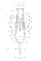
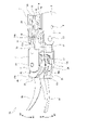
- FIGS. 2 to 13 An embodiment of the surgical instrument of the present invention is shown together with FIGS. 2 to 13, and this figure is a schematic perspective view showing a surgical robot and the like with the surgical instrument attached.
- the surgical instrument according to the first embodiment is shown together with FIGS. 3 to 7, and this figure is a side view. It is a top view.
- FIG. 4 is a perspective view showing a state in which the first blade portion and the second blade portion are opened;
- FIG. 4 is a perspective view showing a state in which the first blade portion and the second blade portion are closed;
- FIG. 4 is a conceptual diagram for explaining the moment generated in the opening operation and the force generated in the blade portion;
- FIG. 4 is a conceptual diagram for explaining the moment generated in the closing operation and the force generated in the blade portion;
- the surgical instrument according to the second embodiment is shown together with FIGS. 9 to 13, and this figure is a side view. It is a top view.
- FIG. 4 is a perspective view showing a state in which the first blade portion and the second blade portion are opened;
- FIG. 4 is a perspective view showing a state in which the first blade portion and the second blade portion are closed;
- FIG. 4 is a conceptual diagram for explaining the moment generated in the opening operation and the force generated in the blade portion;
- FIG. 4 is a conceptual diagram for explaining the moment generated in the closing operation and the force generated in the blade portion;
- the embodiment shown below shows an example in which the surgical instrument of the present invention is applied to a type that is used by being installed on the floor of an operating room or the like.
- the scope of application of the surgical instrument of the present invention is not limited to the type that is used by being installed on the floor of the operating room, etc., and the surgical instrument of the present invention is not limited to the type that is used by being attached to the ceiling or wall of the operating room. can also be applied.
- the surgical instrument shown below is formed in a shape having a longitudinal direction and is provided with a plurality of pulleys arranged side by side on the end effector.
- the direction in which they are arranged will be described as the vertical direction.
- the front, rear, up, down, left, and right directions shown below are for convenience of explanation, and the implementation of the present invention is not limited to these directions.
- An operating table 100 is installed in the operating room, and a patient 200 is laid on the operating table 100, for example, in a supine state.
- a port 202 is formed in a body cavity 201 of the patient 200, eg, in the abdominal wall.
- a portion (tip) of the surgical instrument 1 is inserted into the port 202 when a surgical operation is performed.
- Port 202 is a small hole into which surgical instrument 1 is inserted.
- the surgical robot 50 has a base 51 to be placed on the floor of an operating room or the like, a shaft-shaped pole 52 fixed to the base 51 , and a main body 53 supported by the pole 52 .
- the base 51 is installed on the floor or the like on the side of the operating table 100, and the lower end of the pole 52 is fixed to the base 51 while extending vertically.
- the main body 53 has, for example, a first support arm 54, a second support arm 55, a first connecting arm 56 and a second connecting arm 57.
- the first support arm 54, the second support arm 55, the first connecting arm 56 and the second connecting arm 57 function as robot arms.
- the first support arm 54 is formed in a shape extending in the horizontal direction, and one end portion in the longitudinal direction is provided as a supported tubular portion 54a.
- the pole 52 is inserted through the supported cylindrical portion 54a of the first support arm 54.
- the first support arm 54 is manually or electrically movable with respect to the pole 52, and the supported cylindrical portion 54a serves as a fulcrum with respect to the pole 52. It is made rotatable in the direction around the axis as.
- the first support arm 54 can be fixed to the pole 52 at a desired position in the vertical direction and at a desired position in the axial direction.
- the second support arm 55 is formed in a shape extending in the horizontal direction, and one end in the longitudinal direction is rotatably connected to the other end in the longitudinal direction of the first support arm 54 .
- the second support arm 55 is rotatable with respect to the first support arm 54 manually or electrically.
- One end of the first connecting arm 56 in the longitudinal direction is connected to the other end in the longitudinal direction of the second support arm 55 , and is rotatable with respect to the second support arm 55 and extends in the longitudinal direction. It is made rotatable in the direction of rotation.
- the first connecting arm 56 is manually or electrically rotated with respect to the second support arm 55 .
- the second connecting arm 57 has one end in the longitudinal direction connected to the other end in the longitudinal direction of the first connecting arm 56, and is rotatable with respect to the first connecting arm 56 and extends in the longitudinal direction. It is made rotatable in the direction of rotation.
- the second connecting arm 57 is manually or electrically rotated with respect to the first connecting arm 56 or rotated about the axis.
- the second connecting arm 57 is provided with a mounting portion 57a at the other end in the longitudinal direction.
- the surgical robot 50 having the structure in which the first support arm 54, the second support arm 55, the first connection arm 56 and the second connection arm 57 are connected in order is shown as an example.
- the number of robot arms (support arms and connecting arms) provided in the surgical robot 50 is arbitrary, and the surgical robot 50 may be provided with at least one robot arm.
- the surgical robot 50 is used in surgical operations.
- the surgical robot 50 installed in the operating room is remotely operated by an operator (doctor) using a master-slave system.
- the master-slave system is a method in which roles are shared between a master device that controls and operates multiple devices and a slave device that operates under the control of the master device when multiple devices operate in cooperation.
- an operating device (control device) (not shown) operated by an operator is used as a master machine, and the surgical robot 50 is used as a slave machine.
- the surgical robot 50 In a surgical operation, when an operation signal to be executed by the surgical robot 50 is input by the operator to the operation device, the operation signal is transmitted from the operation device to the surgical robot 50 via a control unit (not shown).
- a control unit not shown
- the first connecting arm 56, the second connecting arm 57, the surgical instrument 1, etc. are operated according to the input operation signal.
- the surgical robot 50 may be provided with a camera unit that functions as an endoscope, for example, and may be configured such that the camera unit takes pictures in accordance with an input motion signal.
- the first connecting arm 56 is moved vertically with respect to the pole 52 according to the position of the patient 200 to set the vertical position of the main body 53 . Then, according to the operation position, the first connecting arm 56 is rotated with respect to the pole 52 and the second connecting arm 57 is rotated with respect to the first connecting arm 56 to determine the position of the surgical instrument 1. set.
- a pivot point is set as a reference point for movement of the surgical instrument 1.
- the pivot point is a position that approximately coincides with the port 202 into which the surgical instrument 1 is inserted, and where a trocar is used, approximately coincides with the position of the trocar. Therefore, when the surgical instrument 1 is inserted into the body cavity 201 of the patient 200, the position of the surgical instrument 1 is controlled such that a portion of the surgical instrument 1 always passes through the pivot point, and a proper pivot operation is performed. By performing a proper pivot operation, the position of the surgical instrument 1 at the pivot point is not changed, and the occurrence of load on tissues near the body surface of the patient 200 is prevented to ensure safety.
- the surgical instrument 1 is attachable to and detachable from the mounting portion 57a of the second connecting arm 57.
- a surgical instrument 1 has a base body 2 , a support body 3 and an end effector 4 .
- the base body 2 has a substantially cylindrical mounting portion 5 whose axial direction is the front-rear direction, and support arm portions 6, 6 projecting forward from the front end portion of the mounting portion 5, respectively.
- the attached portion 5 is a portion attached to the attaching portion 57 a of the second connecting arm 57 in the surgical robot 50 .
- the support arm portions 6, 6 protrude forward from positions on opposite sides of the attached portion 5 by 180 degrees.
- Both ends of the first support shaft 7 in the axial direction are connected to the rear ends of the support arms 6 , 6 .
- the axial direction of the first support shaft 7 is the horizontal direction.
- First auxiliary pulleys 8, 8 are rotatably supported at positions near both ends of the first support shaft 7 in the axial direction.
- the first auxiliary pulleys 8,8 are positioned adjacent to the inner surfaces of the support arms 6,6 respectively.
- the second support shafts 9, 9 are connected to the central portions of the support arms 6, 6 in the front-rear direction, respectively.
- the axial direction of the second support shaft 9 is the horizontal direction.
- Second auxiliary pulleys 10, 10 are rotatably supported on the second support shafts 9, 9, respectively.
- the second auxiliary pulley 10 is composed of two pulley portions 10a and 10b that are axially aligned and positioned near the inner surface of the support arm portion 6. As shown in FIG.
- the pulley portions 10a, 10a are positioned inside in the left-right direction, and the pulley portions 10b, 10b are positioned outside the pulley portions 10a, 10a in the left-right direction.
- the support 3 is composed of a wire support portion 11 and pulley support portions 12, 12, and the pulley support portions 12, 12 protrude forward from both left and right ends of the wire support portion 11, respectively.
- the wire support part 11 is formed in a flat shape with the left-right direction being the thickness direction, and has a wire connecting groove 11a in the central part in the thickness direction.
- the pulley support parts 12, 12 protrude forward from the upper and lower ends of the wire support part 11, respectively.
- Both ends of the fulcrum shafts 13, 13 in the axial direction are connected to the front ends of the support arm portions 6, 6 and the wire support portion 11, respectively.
- the axial direction of the fulcrum shaft 13 is the horizontal direction.
- Third auxiliary pulleys 14, 14 are rotatably supported on the fulcrum shafts 13, 13, respectively.
- the third auxiliary pulley 14 is composed of two pulley portions 14a and 14b aligned in the axial direction.
- the pulley portions 14a, 14a are positioned inside in the left-right direction, and the pulley portions 14b, 14b are positioned outside the pulley portions 14a, 14a in the left-right direction.
- a support wire 15 is inserted into the wire connecting groove 11 a formed in the wire support portion 11 of the support 3 , and the support wire 15 is wound around the wire support portion 11 .
- the support 3 is rotated about the fulcrum shaft 13 in a direction in which the front end portion is moved upward with respect to the base 2, and the support wire 15 is pulled in the other direction.
- the support member 3 is pivoted about the fulcrum shaft 13 in a direction in which the front end portion is moved downward with respect to the base member 2 .
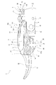
- the end effector 4 is composed of a first jaw 16 and a second jaw 17.
- the first jaw 16 is, for example, a portion that constitutes the left (L side) scissors
- the second jaw 17 is, for example, a portion that constitutes the right (R side) scissors.
- the end effector 4 is rotatably supported by the support 3 with the rotation shaft 18 as a fulcrum.
- the rotation shaft 18 has an axial direction that extends vertically, and both ends in the axial direction are connected to the pulley support portions 12 , 12 of the support body 3 , respectively.
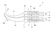
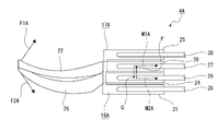
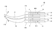
- the first jaw 16 includes a first base portion 19 formed in a plate shape facing in a substantially front-rear direction, a first opening pulley 20 projecting rearward from an upper end portion of the first base portion 19, It has a first closing pulley 21 protruding rearward from the lower end of the first base portion 19 and a first blade portion 22 protruding forward from a position near the upper end of the first base portion 19 . doing.
- the first jaw 16 has a first base portion 19, a first opening pulley 20, a first closing pulley 21, and a first blade portion 22, for example, which are integrally formed.
- the first jaw 16 has the first base portion 19, the first blade portion 22, the first opening pulley 20, and the first closing pulley 21 integrally formed. Since the jaw 16 is formed of one member, the manufacturing cost of the surgical instrument 1 can be reduced.
- the first jaw 16 is rotatable with respect to the support 3 with the pivot shaft 18 passing through the center of the first opening pulley 20 and the first closing pulley 21 . It is
- the rotating shaft 18 is vertically oriented, and the support 3 is rotated relative to the base 2 around the fulcrum shaft 13, which is vertically oriented. Therefore, the direction of rotation of the first jaw 16 with respect to the support 3 and the direction of rotation of the support 3 with respect to the base 2 are perpendicular to each other.
- the first jaw 16 Since the first opening pulley 20 and the first closing pulley 21 protrude rearward from both upper and lower ends of the first base portion 19, the first jaw 16 is arranged so that the first opening pulley 20 and the first blocking pulley 21, and this space is formed as the first space 16a.
- the first blade part 22 is formed, for example, in a downwardly curved curved shape, and is provided as one blade part for excising the affected part of the patient.
- the first blade portion 22 protrudes forward from a position closer to the first opening pulley 20 in the direction in which the first opening pulley 20 and the first closing pulley 21 are aligned.
- the second jaw 17 includes a second base portion 23 formed in a plate shape facing in the front-rear direction, a second opening pulley 24 projecting rearward from the lower end portion of the second base portion 23, It has a second closing pulley 25 protruding rearward from the upper end of the second base portion 23 and a second blade portion 26 protruding forward from a position near the lower end of the second base portion 23 . doing.
- a second base portion 23 In the second jaw 17, a second base portion 23, a second opening pulley 24, a second closing pulley 25, and a second blade portion 26 are integrally formed, for example.
- the second jaw 17 has the second base portion 23, the second blade portion 26, the second opening pulley 24, and the second closing pulley 25 integrally formed. Since the jaw 17 is formed of one member, the manufacturing cost of the surgical instrument 1 can be reduced.
- the second jaw 17 is rotatable with respect to the support 3 with the pivot shaft 18 passing through the center of the second opening pulley 24 and the second closing pulley 25 . It is
- the rotating shaft 18 is vertically oriented, and the support 3 is rotated relative to the base 2 around the fulcrum shaft 13, which is vertically oriented. Therefore, the direction of rotation of the second jaw 17 with respect to the support 3 and the direction of rotation of the support 3 with respect to the base 2 are perpendicular to each other.
- the second jaw 17 is configured such that the second opening pulley 24 and the second blocking pulley 25, and this space is formed as the second space 17a.
- the second blade portion 26 is formed, for example, in a downwardly curved curved shape, and is provided as the other blade portion for resecting the affected part of the patient.
- the second blade portion 26 protrudes forward from a position closer to the second opening pulley 24 in the direction in which the second opening pulley 24 and the second closing pulley 25 are aligned.
- the first jaw 16 and the second jaw 17 are rotated in the closing direction (H1 shown in FIG. 4) with the rotation shaft 18 as a fulcrum, so that the first blade portion 22 provided as one blade portion and the The second blade portion 26 provided as the other blade portion is moved toward each other.
- the first jaw 16 and the second jaw 17 By rotating the first jaw 16 and the second jaw 17 in the closing direction, for example, excision of an affected part of a patient is performed.
- first jaw 16 and the second jaw 17 are rotated in the opening direction (H2 shown in FIG. 4) about the rotation shaft 18, whereby the first blade portion 22 and the second blade portion 26 are opened. are moved away from each other.
- the first blade portion 22 and the second blade portion 26 are attached to the tissue such as a blood vessel.
- a treatment or the like is performed to widen the hole formed in the tissue in the inserted state.
- the rotation shaft 18 passes through the first opening pulley 20, the first closing pulley 21, the second opening pulley 24, and the second closing pulley 25, thereby opening the first opening.
- a second closing pulley 25 is positioned in the first space 16 a between the opening pulley 20 and the first closing pulley 21 , and a second closing pulley 24 between the second opening pulley 24 and the second closing pulley 25 .
- a first closing pulley 21 is positioned in the second space 17a. Therefore, the end effector 4 has a first opening pulley 20, a second closing pulley 25, a first closing pulley 21, and a second opening pulley 24 arranged in this order in the axial direction of the rotation shaft 18. is in a state of
- One end of a first opening wire 27 is connected to the first opening pulley 20 of the first jaw 16 .
- the first opening wire 27 is wound around the pulley portion 14a of the third auxiliary pulley 14 and the pulley portion 10a of the second auxiliary pulley 10 in order from the first opening pulley 20 side.
- first closing wire 28 is connected to the first closing pulley 21 of the first jaw 16 .
- the first closing wire 28 is wound around the pulley portion 14b of the third auxiliary pulley 14, the pulley portion 10b of the second auxiliary pulley 10, and the first auxiliary pulley 8 in order from the first closing pulley 21 side.
- One end of a second opening wire 29 is connected to the second opening pulley 24 of the second jaw 17 .
- the second opening wire 29 is wound around the pulley portion 14a of the third auxiliary pulley 14 and the pulley portion 10a of the second auxiliary pulley 10 in order from the second opening pulley 24 side.
- One end of a second closing wire 30 is connected to the second closing pulley 25 of the second jaw 17 .
- the second closing wire 30 is wound around the pulley portion 14b of the third auxiliary pulley 14, the pulley portion 10b of the second auxiliary pulley 10, and the first auxiliary pulley 8 in order from the second closing pulley 25 side.
- the first opening wire 27 connected to the first opening pulley 20 When the first opening wire 27 connected to the first opening pulley 20 is pulled, the first jaw 16 rotates in one direction about the pivot shaft 18, and the first jaw 16 moves in the opening direction. operated (see FIG. 4). At this time, the first closing wire 28 connected to the first closing pulley 21 is pulled back in the direction of winding around the first closing pulley 21 as the first jaw 16 moves in the opening direction.
- the opening operation of the first jaw 16 and the opening operation of the second jaw 17 are performed simultaneously, and the first blade portion 22 and the second blade portion 26 are separated from each other by the opening operation.
- an operation is performed to widen the size of a hole formed in a tissue such as a blood vessel.
- the closing operation of the first jaw 16 and the closing operation of the second jaw 17 are performed simultaneously, and the first blade portion 22 and the second blade portion 26 are moved toward each other by the closing operation. For example, excision of an affected part of a patient is performed.
- the first opening pulley 20 is positioned more than the second blade portion 26 with respect to the first closing pulley 21 in the direction (vertical direction) perpendicular to the opening/closing direction (H shown in FIG. 3). 1 is positioned on the blade portion 22 side.
- a force F1A is applied to the first blade portion 22 in a direction away from the second blade portion 26 by a rotational moment M1A based on the midpoint P in the direction in which the pulleys 21 are arranged (see FIG. 6).
- the first closing pulley 21 is positioned closer to the second blade portion 26 than the first blade portion 22 with respect to the first opening pulley 20 in the direction perpendicular to the opening/closing direction. ing.
- the second opening pulley 24 is located closer to the second blade portion 26 than the first blade portion 22 with respect to the second closing pulley 25 in the direction perpendicular to the opening/closing direction. ing.
- a force F2A is applied to the second blade portion 26 in a direction away from the first blade portion 22 by a rotational moment M2A based on the midpoint Q in the direction in which the pulleys 25 are arranged (see FIG. 6).
- the second closing pulley 25 is positioned closer to the first blade portion 22 than the second blade portion 26 with respect to the second opening pulley 24 in the direction orthogonal to the opening/closing direction. ing.
- the rotational moment M1A and the rotational moment M2A imparts a force in the direction perpendicular to the direction of the opening motion to the first blade portion 22 and the second blade portion 26 in directions away from each other (see FIG. 6).
- first blade portion 22 and the second blade portion 26 are inserted into a tissue such as a blood vessel and the operation is performed to expand the size of a hole formed in the tissue
- a small driving force can be used to reduce the driving force at a low speed or constant.
- the opening operation can be performed at a speed of .
- the first blade portion 22 and the second blade portion 26 are moved from the open state (see FIG. 4) to the closed state (see FIG. 5), the first blade portion 22 and the second blade portion 26 2 of the blade portion 26 can generate good sharpness against shearing resistance, and the stable and smooth closing operation of the end effector 4 can be ensured.
- the excision can be performed without causing significant damage to the tissue, thereby reducing the burden on the patient. Surgery can be performed in this state.
- the support 3 is rotatably connected to the base 2 with the fulcrum shaft 13 as a fulcrum. It is rotated with respect to the base body 2 with the fulcrum shaft 13 as the fulcrum.
- the support 3 is rotatably connected to the base 2 with the fulcrum shaft 13 as a fulcrum, and the axial direction of the rotation shaft 18 serving as the fulcrum of rotation of the end effector 4 with respect to the support 3 and the axial direction of the fulcrum shaft 13 and are oriented perpendicular to each other.
- the end effector 4 can be moved in two orthogonal directions, surgery can be performed with high positional accuracy and a high degree of freedom of movement.
- a second closing pulley 25 is positioned between the first opening pulley 20 and the first closing pulley 21, and a second opening pulley 24 and a second closing pulley.
- a first closing pulley 21 is positioned between the pulleys 25 .
- the pulleys of the first jaw 16 and the pulleys of the second jaw 17 are alternately positioned, the space for arranging the four pulleys in the axial direction of the rotating shaft 18 can be reduced, and the first jaw 16 can be arranged. and the two pulleys of the second jaw 17 can be spaced apart from each other.
- the size of the end effector 4 can be reduced, and in the opening/closing operation, the first blade portion 22 and the second blade portion 26 are applied with a force F1A in a direction away from each other, a force F2A and a force F1B in a direction in which they contact each other. Force F2B can be applied.
- a first opening pulley 20, a second closing pulley 25, a first closing pulley 21, and a second opening pulley 24 are positioned in order in the axial direction of the rotating shaft 18, and are arranged in the opening/closing direction.
- the first release pulley 20 is positioned on the first blade portion 22 side
- the second release pulley 24 is positioned on the second blade portion 26 side.
- the moment is increased especially in the opening operation.
- the first blade portion 22 and the first blade portion 22 in the opening operation A large force applied to the second blade portion 26 in the separating direction can be applied.
- a first base portion 19 is provided on the first jaw 16, and a first opening pulley 20 and a first closing pulley 21 protrude in the same direction from both ends of the first base portion 19,
- a second base portion 23 is provided on the second jaw 17, and a second opening pulley 24 and a second closing pulley 25 protrude from both ends of the second base portion 23 in the same direction.
- both the first jaw 16 and the second jaw 17 are formed in a bifurcated shape, the pulleys of the first jaw 16 and the pulleys of the second jaw 17 can be alternately positioned with a simple structure. It is possible to achieve simplification of the structure and reduction of the manufacturing cost.
- the surgical instrument 1A shown below differs from the surgical instrument 1 described above only in the configuration of the end effector, only the parts that differ from the surgical instrument 1 will be described in detail. Other parts are denoted by the same reference numerals as the same parts in the surgical instrument 1, and descriptions thereof are omitted. Also, in the surgical instrument 1A shown below, the end effector is indicated as an end effector 4A, and the first jaw 16 and the second jaw 17 are indicated as a first jaw 16A and a second jaw 17A, respectively.
- the surgical instrument 1A is attachable to and detachable from the mounting portion 57a of the second connecting arm 57.
- the surgical instrument 1A has a base body 2, a support body 3 and an end effector 4A.
- the end effector 4A is composed of a first jaw 16A and a second jaw 17A.
- the first jaw 16A is, for example, a portion that constitutes the left (L side) scissors
- the second jaw 17A is, for example, a portion that constitutes the right (R side) scissors.
- the end effector 4A is rotatably supported by the support 3 with the rotation shaft 18 as a fulcrum.
- the first jaw 16A includes a first base portion 19 formed in a plate shape facing in the front-rear direction, a first opening pulley 20 projecting rearward from the upper end portion of the first base portion 19, It has a first closing pulley 21 protruding rearward from the lower end of the first base portion 19 and a first blade portion 22 protruding forward from the upper end of the first base portion 19.
- the first jaw 16A has a first base portion 19, a first opening pulley 20, a first closing pulley 21, and a first blade portion 22, for example, which are integrally formed.
- the first jaw 16A has the first base portion 19, the first opening pulley 20, the first closing pulley 21, and the first blade portion 22 integrally formed. Since the jaw 16A is formed of one member, the manufacturing cost of the surgical instrument 1A can be reduced.
- the first jaw 16A is rotatable with respect to the support 3 with the pivot shaft 18 passing through the center of the first opening pulley 20 and the first closing pulley 21. It is
- the rotating shaft 18 is vertically oriented, and the support 3 is rotated relative to the base 2 around the fulcrum shaft 13, which is vertically oriented. Therefore, the rotation direction of the first jaw 16A with respect to the support member 3 and the rotation direction of the support member 3 with respect to the base member 2 are perpendicular to each other.
- the first jaw 16A is configured such that the first opening pulley 20 and the first blocking pulley 21, and this space is formed as the first space 16a.
- the first blade part 22 is formed, for example, in a downwardly curved curved shape, and is provided as one blade part for excising the affected part of the patient.
- the first blade portion 22 protrudes forward from the same portion of the first base portion 19 as the first release pulley 20 protrudes.
- the second jaw 17A includes a second base portion 23 formed in a plate shape facing in the front-rear direction, a second opening pulley 24 projecting rearward from the lower end portion of the second base portion 23, It has a second closing pulley 25 projecting rearward from the upper end of the second base portion 23, and a second blade portion 26 projecting forward from the lower end of the second base portion 23.
- the second base portion 23, the second opening pulley 24, the second closing pulley 25, and the second blade portion 26 are integrally formed, for example.
- the second jaw 17A has the second base portion 23, the second opening pulley 24, the second closing pulley 25, and the second blade portion 26 integrally formed. Since the jaw 17A is made of one member, the manufacturing cost of the surgical instrument 1A can be reduced.
- the second jaw 17A is rotatable with respect to the support 3 with the pivot shaft 18 passing through the center of the second opening pulley 24 and the second closing pulley 25. It is
- the rotating shaft 18 is vertically oriented, and the support 3 is rotated relative to the base 2 around the fulcrum shaft 13, which is vertically oriented. Therefore, the direction of rotation of the second jaw 17A with respect to the support 3 and the direction of rotation of the support 3 with respect to the base 2 are perpendicular to each other.
- the second jaw 17A is configured such that the second opening pulley 24 and the second blocking pulley 25, and this space is formed as the second space 17a.
- the second blade portion 26 is formed, for example, in a downwardly curved curved shape, and is provided as the other blade portion for resecting the affected part of the patient.
- the second blade portion 26 protrudes forward from the same portion of the second base portion 23 as the second release pulley 24 protrudes.
- the first jaw 16A and the second jaw 17A are rotated in the closing direction (H1 shown in FIG. 10) about the rotation shaft 18, thereby opening the first blade portion 22 provided as one of the blade portions.
- the second blade portion 26 provided as the other blade portion is moved toward each other.
- first jaw 16A and the second jaw 17A rotate in the opening direction (H2 shown in FIG. 10) with the rotation shaft 18 as a fulcrum, thereby forming a first blade portion provided as one blade portion. 22 and the second blade portion 26 provided as the other blade portion are moved in a direction to separate from each other.
- a treatment or the like is performed to enlarge the size of the formed hole.
- the rotation shaft 18 passes through the first opening pulley 20, the first closing pulley 21, the second opening pulley 24, and the second closing pulley 25, thereby opening the first opening.
- a second opening pulley 24 is positioned in the first space 16 a between the opening pulley 20 and the first closing pulley 21 , and a second opening pulley 24 between the second opening pulley 24 and the second closing pulley 25 .
- a first opening pulley 20 is positioned in the second space 17a. Therefore, the end effector 4A has the second closing pulley 25, the first opening pulley 20, the second opening pulley 24, and the first closing pulley 21 arranged in order in the axial direction of the rotation shaft 18. is in a state of
- first opening wire 27 is connected to the first opening pulley 20 of the first jaw 16A.
- the first opening wire 27 is wound around the pulley portion 14b of the third auxiliary pulley 14, the pulley portion 10b of the second auxiliary pulley 10, and the first auxiliary pulley 8 in order from the first opening pulley 20 side.
- first closing wire 28 is connected to the first closing pulley 21 of the first jaw 16A.
- the first closing wire 28 is wound around the pulley portion 14a of the third auxiliary pulley 14 and the pulley portion 10a of the second auxiliary pulley 10 in order from the first closing pulley 21 side.
- One end of a second opening wire 29 is connected to the second opening pulley 24 of the second jaw 17 .
- the second opening wire 29 is wound around the pulley portion 14b of the third auxiliary pulley 14, the pulley portion 10b of the second auxiliary pulley 10, and the first auxiliary pulley 8 in order from the second opening pulley 24 side.
- One end of a second closing wire 30 is connected to the second closing pulley 25 of the second jaw 17 .
- the second blocking wire 30 is wound around the pulley portion 14a of the third auxiliary pulley 14 and the pulley portion 10a of the second auxiliary pulley 10 in order from the second blocking pulley 25 side.
- the first opening wire 27 connected to the first opening pulley 20 When the first opening wire 27 connected to the first opening pulley 20 is pulled, the first jaw 16A rotates in one direction about the pivot shaft 18, and the first jaw 16A moves in the opening direction. operated (see FIG. 10). At this time, the first closing wire 28 connected to the first closing pulley 21 is pulled back in the direction of winding around the first closing pulley 21 as the first jaw 16A moves in the opening direction.
- the opening operation of the first jaw 16A and the opening operation of the second jaw 17A are performed simultaneously, and the opening operation separates the first blade portion 22 and the second blade portion 26 from each other.
- an operation is performed to widen the size of a hole formed in a tissue such as a blood vessel.
- the closing operation of the first jaw 16A and the closing operation of the second jaw 17A are performed simultaneously, and the closing operation causes the first blade portion 22 and the second blade portion 26 to move toward each other. For example, excision of an affected part of a patient is performed.
- the first opening pulley 20 moves from the second blade portion 26 to the first closing pulley 21 in the direction (vertical direction) perpendicular to the opening/closing direction (H shown in FIG. 9). 1 is positioned on the blade portion 22 side.
- a force F1A is applied to the first blade portion 22 in a direction away from the second blade portion 26 by a rotational moment M1A based on the midpoint P in the direction in which the pulleys 21 are arranged (see FIG. 12).
- the first closing pulley 21 is located closer to the second blade portion 26 than the first blade portion 22 with respect to the first opening pulley 20 in the direction perpendicular to the opening/closing direction. ing.
- the second opening pulley 24 is positioned closer to the second blade portion 26 than the first blade portion 22 with respect to the second closing pulley 25 in the direction perpendicular to the opening/closing direction. ing.
- a force F2A is applied to the second blade portion 26 in a direction away from the first blade portion 22 by a rotational moment M2A based on the midpoint Q in the direction in which the pulleys 25 are arranged (see FIG. 12).
- the second closing pulley 25 is positioned closer to the first blade portion 22 than the second blade portion 26 with respect to the second opening pulley 24 in the direction perpendicular to the opening/closing direction. ing.
- the rotational moment M1A and the rotational moment M2A applies a force in the direction perpendicular to the direction of the opening motion to the first blade portion 22 and the second blade portion 26 in directions away from each other (see FIG. 12).
- first blade portion 22 and the second blade portion 26 are inserted into a tissue such as a blood vessel and the operation is performed to expand the size of a hole formed in the tissue
- a small driving force can be used to reduce the driving force at a low speed or constant.
- the opening operation can be performed at a speed of .
- the first blade portion 22 and the second blade portion 26 are moved from the open state (see FIG. 10) to the closed state (see FIG. 11), the first blade portion 22 and the second blade portion 26 move. 2 of the blade portion 26 can generate a sharpness that can withstand shearing resistance, and a stable and smooth closing operation of the end effector 4A can be ensured.
- the excision can be performed without causing significant damage to the tissue, thereby reducing the burden on the patient. Surgery can be performed in this state.
- the support 3 is rotatably connected to the base 2 with the fulcrum shaft 13 as the fulcrum. It is rotated with respect to the base body 2 with the fulcrum shaft 13 as the fulcrum.
- the support 3 is rotatably connected to the base 2 with the fulcrum shaft 13 as a fulcrum, and the axial direction of the rotation shaft 18 serving as the fulcrum of rotation of the end effector 4A with respect to the support 3 and the axial direction of the fulcrum shaft 13 and are oriented perpendicular to each other.
- the end effector 4A can be operated in two orthogonal directions, surgery can be performed with high positional accuracy and a high degree of freedom of movement.
- a second opening pulley 24 is positioned between the first opening pulley 20 and the first closing pulley 21, and the second opening pulley 24 and the second closing pulley 24 are positioned between the first opening pulley 20 and the first closing pulley 21.
- a first opening pulley 20 is positioned between the pulleys 25 .
- the pulleys of the first jaw 16A and the pulleys of the second jaw 17A are alternately positioned, the space for arranging the four pulleys in the axial direction of the rotating shaft 18 can be reduced and the first jaw 16A can be arranged. and the two pulleys of the second jaw 17A can be spaced apart from each other.
- the size of the end effector 4A can be reduced, and in the opening/closing operation, the first blade portion 22 and the second blade portion 26 are applied with a force F1A in a direction away from each other, a force F2A and a force F1B in a direction contacting each other, Force F2B can be applied.
- the second closing pulley 25, the first opening pulley 20, the second opening pulley 24, and the first closing pulley 21 are positioned in this order in the axial direction of the rotating shaft 18, and are arranged in the opening/closing direction.
- the second closing pulley 25 is positioned on the first blade portion 22 side
- the first closing pulley 21 is positioned on the second blade portion 26 side.
- the second closing pulley 25 and the first closing pulley 21 are located on both sides of the first opening pulley 20 and the second opening pulley 24, they increase the moment, especially in the closing operation. After applying an appropriate force in the separating direction applied to the first blade portion 22 and the second blade portion 26 in the opening operation, the first blade portion 22 in the closing operation and a large force applied to the second blade portion 26 in the contact direction.
- a first base portion 19 is provided on the first jaw 16A, and a first opening pulley 20 and a first closing pulley 21 protrude in the same direction from both ends of the first base portion 19,
- a second base portion 23 is provided on the second jaw 17A, and a second opening pulley 24 and a second closing pulley 25 protrude from both ends of the second base portion 23 in the same direction.
- both the first jaw 16A and the second jaw 17A are formed in a bifurcated shape, the pulleys of the first jaw 16A and the pulleys of the second jaw 17A can be alternately positioned with a simple structure. It is possible to achieve simplification of the structure and reduction of the manufacturing cost.
- the first blade portion 22 and the second blade portion 26 are pulled by the first opening wire 27 and the second opening wire 29, respectively.
- the first occluding wire 28 and the second occluding wire 30 are pulled, respectively, to move them closer together.
- the first opening pulley 20 is positioned closer to the first blade portion 22 than the second blade portion 26 with respect to the first closing pulley 21, and is perpendicular to the opening/closing direction.
- a second opening pulley 24 is positioned on the side of the first blade portion 22 from the second blade portion 26 with respect to the second closing pulley 25 in the direction.
- the first blade portion 22 and the second blade portion 26 move toward each other in the direction orthogonal to the opening/closing direction due to the moments M1A and M2A generated when the first jaw 16 and the second jaw 17 are opened, respectively.
- a direction orthogonal to the opening/closing direction is applied to the first blade portion 22 and the second blade portion 26 by the moments M1B and M2B generated in the closing operation of the first jaw 16 and the second jaw 17, respectively, while the force is applied.
- a force is applied in directions away from each other, so that the end effectors 4 and 4A can be stably and highly accurately operated.
Landscapes
- Health & Medical Sciences (AREA)
- Surgery (AREA)
- Life Sciences & Earth Sciences (AREA)
- Engineering & Computer Science (AREA)
- Medical Informatics (AREA)
- Biomedical Technology (AREA)
- Heart & Thoracic Surgery (AREA)
- Nuclear Medicine, Radiotherapy & Molecular Imaging (AREA)
- Molecular Biology (AREA)
- Animal Behavior & Ethology (AREA)
- General Health & Medical Sciences (AREA)
- Public Health (AREA)
- Veterinary Medicine (AREA)
- Robotics (AREA)
- Pathology (AREA)
- Surgical Instruments (AREA)
Abstract
Description
先ず、手術器具1又は手術器具1Aが装着される手術用ロボット50の一例における概略構成について説明する(図1参照)。尚、後述するように、手術器具1は第1の実施の形態に係る手術器具であり、手術器具1Aは第2の実施の形態に係る手術器具である。
次に、手術器具1又は手術器具1Aが取り付けられる手術用ロボット50の動作についての概略を説明する。
次いで、第1の実施の形態に係る手術器具1の構成について説明する(図2乃至図5参照)。
以下に、手術器具1における動作について説明する(図4乃至図7参照)。
次いで、第2の実施の形態に係る手術器具1Aの構成について説明する(図8乃至図11参照)。
以下に、手術器具1Aにおける動作について説明する(図10乃至図13参照)。
以上に記載した通り、手術器具1及び手術器具1Aにあっては、第1のブレード部22と第2のブレード部26はそれぞれ第1の開放用ワイヤー27と第2の開放用ワイヤー29が引っ張られることにより互いに離隔する開放方向へ動作されると共にそれぞれ第1の閉塞用ワイヤー28と第2の閉塞用ワイヤー30が引っ張られることにより互いに近付く閉塞方向へ動作される。また、開閉方向に直交する方向において第1の開放用プーリー20が第1の閉塞用プーリー21に対して第2のブレード部26より第1のブレード部22側に位置され、開閉方向に直交する方向において第2の開放用プーリー24が第2の閉塞用プーリー25に対して第2のブレード部26より第1のブレード部22側に位置されている。
54 第1の支持アーム(ロボットアーム)
55 第2の支持アーム(ロボットアーム)
56 第1の連結アーム(ロボットアーム)
57 第2の連結アーム(ロボットアーム)
1 手術器具
2 ベース体
3 支持体
4 エンドエフェクター
13 支点軸
16 第1のジョー
17 第2のジョー
18 回動軸
19 第1のベース部
20 第1の開放用プーリー
21 第1の閉塞用プーリー
22 第1のブレード部
23 第2のベース部
24 第2の開放用プーリー
25 第2の閉塞用プーリー
26 第2のブレード部
27 第1の開放用ワイヤー
28 第1の閉塞用ワイヤー
29 第2の開放用ワイヤー
30 第2の閉塞用ワイヤー
1A 手術器具
4A エンドエフェクター
16A 第1のジョー
17A 第2のジョー
Claims (7)
- 手術用のロボットアームに取り付けられる手術器具であって、
前記ロボットアームに着脱可能にされたベース体と、
前記ベース体に連結された支持体と、
前記支持体に回動軸を支点としてそれぞれ回動可能に支持された第1のジョーと第2のジョーを有するエンドエフェクターとを備え、
前記第1のジョーは第1の開放用ワイヤーが連結された第1の開放用プーリーと第1の閉塞用ワイヤーが連結された第1の閉塞用プーリーと開閉方向へ動作される第1のブレード部とを有し、
前記第2のジョーは第2の開放用ワイヤーが連結された第2の開放用プーリーと第2の閉塞用ワイヤーが連結された第2の閉塞用プーリーと前記開閉方向へ動作される第2のブレード部とを有し、
前記第1の開放用プーリーと前記第1の閉塞用プーリーが前記回動軸の軸方向において離隔した状態でそれぞれ前記回動軸に支持され、
前記第2の開放用プーリーと前記第2の閉塞用プーリーが前記回動軸の軸方向において離隔した状態でそれぞれ前記回動軸に支持され、
前記第1のブレード部と前記第2のブレード部はそれぞれ前記第1の開放用ワイヤーと前記第2の開放用ワイヤーが引っ張られることにより互いに離隔する開放方向へ動作されると共にそれぞれ前記第1の閉塞用ワイヤーと前記第2の閉塞用ワイヤーが引っ張られることにより互いに近付く閉塞方向へ動作され、
前記開閉方向に直交する方向において前記第1の開放用プーリーが前記第1の閉塞用プーリーに対して前記第2のブレード部より前記第1のブレード部側に位置され、
前記開閉方向に直交する方向において前記第2の開放用プーリーが前記第2の閉塞用プーリーに対して前記第1のブレード部より前記第2のブレード部側に位置された
手術器具。 - 前記第1の開放用プーリーと前記第1の閉塞用プーリーの間に前記第2の開放用プーリー又は前記第2の閉塞用プーリーが位置され、
前記第2の開放用プーリーと前記第2の閉塞用プーリーの間に前記第1の開放用プーリー又は前記第1の閉塞用プーリーが位置された
請求項1に記載の手術器具。 - 前記回動軸の軸方向において順に前記第1の開放用プーリーと前記第2の閉塞用プーリーと前記第1の閉塞用プーリーと前記第2の開放用プーリーが位置され、
前記開閉方向に直交する方向において前記第1の開放用プーリーが前記第1のブレード部側に位置され前記第2の開放用プーリーが前記第2のブレード部側に位置された
請求項2に記載の手術器具。 - 前記回動軸の軸方向において順に前記第2の閉塞用プーリーと前記第1の開放用プーリーと前記第2の開放用プーリーと前記第1の閉塞用プーリーが位置され、
前記第1のブレード部と前記第2のブレード部の並び方向において前記第2の閉塞用プーリーが前記第1のブレード部側に位置され前記第1の閉塞用プーリーが前記第2のブレード部側に位置された
請求項2に記載の手術器具。 - 前記第1のジョーに第1のベース部が設けられると共に前記第1の開放用プーリーと前記第1の閉塞用プーリーが前記第1のベース部の両端部から同じ方向に突出され、
前記第2のジョーに第2のベース部が設けられると共に前記第2の開放用プーリーと前記第2の閉塞用プーリーが前記第2のベース部の両端部から同じ方向に突出された
請求項2、請求項3又は請求項4に記載の手術器具。 - 前記第1のベース部と前記第1のブレード部と前記第1の開放用プーリーと前記第1の閉塞用プーリーが一体に形成され、
前記第2のベース部と前記第2のブレード部と前記第2の開放用プーリーと前記第2の閉塞用プーリーが一体に形成された
請求項5に記載の手術器具。 - 前記支持体が前記ベース体に支点軸を支点として回動可能に連結され、
前記回動軸の軸方向と前記支点軸の軸方向とが直交する方向にされた
請求項1、請求項2、請求項3、請求項4、請求項5又は請求項6に記載の手術器具。
Priority Applications (5)
| Application Number | Priority Date | Filing Date | Title |
|---|---|---|---|
| CN202180096230.0A CN117042714B (zh) | 2021-06-30 | 2021-06-30 | 手术器具 |
| JP2021552220A JP7017286B1 (ja) | 2021-06-30 | 2021-06-30 | 手術器具 |
| EP21948382.3A EP4316401A4 (en) | 2021-06-30 | 2021-06-30 | SURGICAL INSTRUMENT |
| PCT/JP2021/024855 WO2023276077A1 (ja) | 2021-06-30 | 2021-06-30 | 手術器具 |
| US18/396,322 US20240138873A1 (en) | 2021-06-30 | 2023-12-26 | Surgical instrument |
Applications Claiming Priority (1)
| Application Number | Priority Date | Filing Date | Title |
|---|---|---|---|
| PCT/JP2021/024855 WO2023276077A1 (ja) | 2021-06-30 | 2021-06-30 | 手術器具 |
Related Child Applications (1)
| Application Number | Title | Priority Date | Filing Date |
|---|---|---|---|
| US18/396,322 Continuation US20240138873A1 (en) | 2021-06-30 | 2023-12-26 | Surgical instrument |
Publications (1)
| Publication Number | Publication Date |
|---|---|
| WO2023276077A1 true WO2023276077A1 (ja) | 2023-01-05 |
Family
ID=80844055
Family Applications (1)
| Application Number | Title | Priority Date | Filing Date |
|---|---|---|---|
| PCT/JP2021/024855 Ceased WO2023276077A1 (ja) | 2021-06-30 | 2021-06-30 | 手術器具 |
Country Status (5)
| Country | Link |
|---|---|
| US (1) | US20240138873A1 (ja) |
| EP (1) | EP4316401A4 (ja) |
| JP (1) | JP7017286B1 (ja) |
| CN (1) | CN117042714B (ja) |
| WO (1) | WO2023276077A1 (ja) |
Citations (5)
| Publication number | Priority date | Publication date | Assignee | Title |
|---|---|---|---|---|
| CN107049477A (zh) * | 2017-04-28 | 2017-08-18 | 哈尔滨思哲睿智能医疗设备有限公司 | 一种定位导向手术电凝剪刀 |
| CN109009414A (zh) * | 2018-08-23 | 2018-12-18 | 微创(上海)医疗机器人有限公司 | 手术器械及其末端执行器 |
| US20210038215A1 (en) * | 2017-10-05 | 2021-02-11 | Ethicon Llc | Surgical tools with occluded blade |
| JP6850517B1 (ja) * | 2020-09-10 | 2021-03-31 | リバーフィールド株式会社 | 鉗子装置及び鉗子装置の製造方法 |
| JP2021049276A (ja) | 2019-09-26 | 2021-04-01 | 株式会社メディカロイド | 手術器具 |
Family Cites Families (8)
| Publication number | Priority date | Publication date | Assignee | Title |
|---|---|---|---|---|
| US9204923B2 (en) * | 2008-07-16 | 2015-12-08 | Intuitive Surgical Operations, Inc. | Medical instrument electronically energized using drive cables |
| EP3900641A1 (en) * | 2013-03-14 | 2021-10-27 | SRI International Inc. | Wrist and grasper system for a robotic tool |
| WO2016068204A1 (ja) * | 2014-10-29 | 2016-05-06 | 住友ベークライト株式会社 | 内視鏡用鋏及び内視鏡用高周波処置具 |
| GB2554915B (en) * | 2016-10-14 | 2022-03-02 | Cmr Surgical Ltd | Driving arrangement for articulating a surgical instrument |
| US10743948B2 (en) * | 2016-12-07 | 2020-08-18 | Ethicon Llc | Surgical tool wrists |
| CN110382179A (zh) * | 2017-02-27 | 2019-10-25 | 朝日英达科株式会社 | 操纵器 |
| US11628028B2 (en) * | 2018-12-31 | 2023-04-18 | Asensus Surgical Us, Inc. | Articulating surgical instrument |
| JP2021041037A (ja) * | 2019-09-13 | 2021-03-18 | ソニー株式会社 | 術具、手術支援システム、並びに手術用操作ユニット |
-
2021
- 2021-06-30 CN CN202180096230.0A patent/CN117042714B/zh active Active
- 2021-06-30 WO PCT/JP2021/024855 patent/WO2023276077A1/ja not_active Ceased
- 2021-06-30 EP EP21948382.3A patent/EP4316401A4/en active Pending
- 2021-06-30 JP JP2021552220A patent/JP7017286B1/ja active Active
-
2023
- 2023-12-26 US US18/396,322 patent/US20240138873A1/en active Pending
Patent Citations (5)
| Publication number | Priority date | Publication date | Assignee | Title |
|---|---|---|---|---|
| CN107049477A (zh) * | 2017-04-28 | 2017-08-18 | 哈尔滨思哲睿智能医疗设备有限公司 | 一种定位导向手术电凝剪刀 |
| US20210038215A1 (en) * | 2017-10-05 | 2021-02-11 | Ethicon Llc | Surgical tools with occluded blade |
| CN109009414A (zh) * | 2018-08-23 | 2018-12-18 | 微创(上海)医疗机器人有限公司 | 手术器械及其末端执行器 |
| JP2021049276A (ja) | 2019-09-26 | 2021-04-01 | 株式会社メディカロイド | 手術器具 |
| JP6850517B1 (ja) * | 2020-09-10 | 2021-03-31 | リバーフィールド株式会社 | 鉗子装置及び鉗子装置の製造方法 |
Non-Patent Citations (1)
| Title |
|---|
| See also references of EP4316401A4 |
Also Published As
| Publication number | Publication date |
|---|---|
| EP4316401A4 (en) | 2024-07-31 |
| CN117042714B (zh) | 2024-05-28 |
| JPWO2023276077A1 (ja) | 2023-01-05 |
| EP4316401A1 (en) | 2024-02-07 |
| US20240138873A1 (en) | 2024-05-02 |
| CN117042714A (zh) | 2023-11-10 |
| JP7017286B1 (ja) | 2022-02-08 |
Similar Documents
| Publication | Publication Date | Title |
|---|---|---|
| US12297894B2 (en) | Instrument transmission converting roll to linear actuation | |
| US20230119001A1 (en) | Jointed control platform | |
| US12458459B2 (en) | Medical devices having three tool members | |
| JP4347043B2 (ja) | プラットフォーム関節手首 | |
| CN113679449B (zh) | 铰接超声手术仪器和系统 | |
| US8597182B2 (en) | Robotic endoscopic retractor for use in minimally invasive surgery | |
| US9713500B2 (en) | Surgical robot control apparatus | |
| KR102218959B1 (ko) | 이중 제어 수술 기기를 위한 시스템 및 방법 | |
| US11147642B2 (en) | Systems, devices, and methods for performing surgical actions via externally driven driving assemblies | |
| KR20150126952A (ko) | 영공간 운동과 동시적인 영직교공간 내에서의 클러칭에 의해 매니퓰레이터를 포지셔닝시키기 위한 시스템 및 방법 | |
| KR20150023290A (ko) | 영공간을 이용한 수술 머니퓰레이터의 명령된 재구성을 위한 시스템 및 방법 | |
| KR20150126950A (ko) | 영공간을 이용하여 경로를 추적하기 위한 시스템 및 방법 | |
| US20210196416A1 (en) | Surgical instrument | |
| JP2002504863A (ja) | 向上した巧緻性および感度で最低侵襲性外科手術を行うための連結外科手術器具 | |
| JP2008289902A (ja) | 遠隔操縦ロボットシステム用の外科手術マニピュレーター | |
| JP2011200593A (ja) | 医療器具 | |
| US20130103199A1 (en) | Surgical robot control apparatus | |
| US20230293160A1 (en) | Surgical instrument wrist | |
| CN113679450A (zh) | 铰接超声手术仪器和系统 | |
| KR20140036417A (ko) | 수술 로봇 | |
| KR20120068097A (ko) | 수술기구, 로봇 암 및 이를 포함하는 수술용 로봇 시스템 | |
| JP2024520809A (ja) | ロボット外科用システムにおける吸引及び灌注弁並びにそれをプライミングする方法 | |
| JP7017286B1 (ja) | 手術器具 | |
| KR101241809B1 (ko) | 수술용 로봇 | |
| CN117796909A (zh) | 手术器械及手术机器人 |
Legal Events
| Date | Code | Title | Description |
|---|---|---|---|
| ENP | Entry into the national phase |
Ref document number: 2021552220 Country of ref document: JP Kind code of ref document: A |
|
| 121 | Ep: the epo has been informed by wipo that ep was designated in this application |
Ref document number: 21948382 Country of ref document: EP Kind code of ref document: A1 |
|
| WWE | Wipo information: entry into national phase |
Ref document number: 202180096230.0 Country of ref document: CN |
|
| WWE | Wipo information: entry into national phase |
Ref document number: 21948382.3 Country of ref document: EP |
|
| WWE | Wipo information: entry into national phase |
Ref document number: 2021948382 Country of ref document: EP |
|
| ENP | Entry into the national phase |
Ref document number: 2021948382 Country of ref document: EP Effective date: 20231031 |
|
| NENP | Non-entry into the national phase |
Ref country code: DE |